EP0549759B1 - Assay module transfer apparatus for use in an automated analytical instrument - Google Patents
Assay module transfer apparatus for use in an automated analytical instrument Download PDFInfo
- Publication number
- EP0549759B1 EP0549759B1 EP92914578A EP92914578A EP0549759B1 EP 0549759 B1 EP0549759 B1 EP 0549759B1 EP 92914578 A EP92914578 A EP 92914578A EP 92914578 A EP92914578 A EP 92914578A EP 0549759 B1 EP0549759 B1 EP 0549759B1
- Authority
- EP
- European Patent Office
- Prior art keywords
- assay module
- assay
- analytical instrument
- automated analytical
- transfer unit
- Prior art date
- Legal status (The legal status is an assumption and is not a legal conclusion. Google has not performed a legal analysis and makes no representation as to the accuracy of the status listed.)
- Expired - Lifetime
Links
- 238000003556 assay Methods 0.000 title claims abstract description 133
- 238000012546 transfer Methods 0.000 title claims abstract description 36
- 239000012530 fluid Substances 0.000 claims abstract description 33
- 238000012360 testing method Methods 0.000 claims abstract description 29
- 230000007246 mechanism Effects 0.000 claims abstract description 21
- 230000002441 reversible effect Effects 0.000 claims description 4
- 230000008878 coupling Effects 0.000 claims description 3
- 238000010168 coupling process Methods 0.000 claims description 3
- 238000005859 coupling reaction Methods 0.000 claims description 3
- 230000008859 change Effects 0.000 description 5
- 239000003153 chemical reaction reagent Substances 0.000 description 5
- 239000000126 substance Substances 0.000 description 5
- 238000006243 chemical reaction Methods 0.000 description 3
- 239000011888 foil Substances 0.000 description 3
- 230000032258 transport Effects 0.000 description 3
- 238000004458 analytical method Methods 0.000 description 2
- 238000000034 method Methods 0.000 description 2
- 238000012545 processing Methods 0.000 description 2
- 238000013459 approach Methods 0.000 description 1
- 238000004891 communication Methods 0.000 description 1
- 238000010276 construction Methods 0.000 description 1
- 201000010099 disease Diseases 0.000 description 1
- 208000037265 diseases, disorders, signs and symptoms Diseases 0.000 description 1
- 230000000984 immunochemical effect Effects 0.000 description 1
- 230000003993 interaction Effects 0.000 description 1
- CNQCVBJFEGMYDW-UHFFFAOYSA-N lawrencium atom Chemical compound [Lr] CNQCVBJFEGMYDW-UHFFFAOYSA-N 0.000 description 1
- 239000007788 liquid Substances 0.000 description 1
- 239000000463 material Substances 0.000 description 1
- 229940126585 therapeutic drug Drugs 0.000 description 1
- 239000010409 thin film Substances 0.000 description 1
Images




Classifications
-
- G—PHYSICS
- G01—MEASURING; TESTING
- G01N—INVESTIGATING OR ANALYSING MATERIALS BY DETERMINING THEIR CHEMICAL OR PHYSICAL PROPERTIES
- G01N35/00—Automatic analysis not limited to methods or materials provided for in any single one of groups G01N1/00 - G01N33/00; Handling materials therefor
- G01N35/00584—Control arrangements for automatic analysers
- G01N35/0092—Scheduling
-
- G—PHYSICS
- G01—MEASURING; TESTING
- G01N—INVESTIGATING OR ANALYSING MATERIALS BY DETERMINING THEIR CHEMICAL OR PHYSICAL PROPERTIES
- G01N35/00—Automatic analysis not limited to methods or materials provided for in any single one of groups G01N1/00 - G01N33/00; Handling materials therefor
- G01N35/00029—Automatic analysis not limited to methods or materials provided for in any single one of groups G01N1/00 - G01N33/00; Handling materials therefor provided with flat sample substrates, e.g. slides
-
- G—PHYSICS
- G01—MEASURING; TESTING
- G01N—INVESTIGATING OR ANALYSING MATERIALS BY DETERMINING THEIR CHEMICAL OR PHYSICAL PROPERTIES
- G01N35/00—Automatic analysis not limited to methods or materials provided for in any single one of groups G01N1/00 - G01N33/00; Handling materials therefor
- G01N35/02—Automatic analysis not limited to methods or materials provided for in any single one of groups G01N1/00 - G01N33/00; Handling materials therefor using a plurality of sample containers moved by a conveyor system past one or more treatment or analysis stations
- G01N35/04—Details of the conveyor system
-
- G—PHYSICS
- G01—MEASURING; TESTING
- G01N—INVESTIGATING OR ANALYSING MATERIALS BY DETERMINING THEIR CHEMICAL OR PHYSICAL PROPERTIES
- G01N35/00—Automatic analysis not limited to methods or materials provided for in any single one of groups G01N1/00 - G01N33/00; Handling materials therefor
- G01N35/00029—Automatic analysis not limited to methods or materials provided for in any single one of groups G01N1/00 - G01N33/00; Handling materials therefor provided with flat sample substrates, e.g. slides
- G01N2035/00039—Transport arrangements specific to flat sample substrates, e.g. pusher blade
- G01N2035/00049—Transport arrangements specific to flat sample substrates, e.g. pusher blade for loading/unloading a carousel
-
- G—PHYSICS
- G01—MEASURING; TESTING
- G01N—INVESTIGATING OR ANALYSING MATERIALS BY DETERMINING THEIR CHEMICAL OR PHYSICAL PROPERTIES
- G01N35/00—Automatic analysis not limited to methods or materials provided for in any single one of groups G01N1/00 - G01N33/00; Handling materials therefor
- G01N35/00029—Automatic analysis not limited to methods or materials provided for in any single one of groups G01N1/00 - G01N33/00; Handling materials therefor provided with flat sample substrates, e.g. slides
- G01N2035/00089—Magazines
-
- G—PHYSICS
- G01—MEASURING; TESTING
- G01N—INVESTIGATING OR ANALYSING MATERIALS BY DETERMINING THEIR CHEMICAL OR PHYSICAL PROPERTIES
- G01N35/00—Automatic analysis not limited to methods or materials provided for in any single one of groups G01N1/00 - G01N33/00; Handling materials therefor
- G01N2035/00178—Special arrangements of analysers
- G01N2035/00277—Special precautions to avoid contamination (e.g. enclosures, glove- boxes, sealed sample carriers, disposal of contaminated material)
-
- G—PHYSICS
- G01—MEASURING; TESTING
- G01N—INVESTIGATING OR ANALYSING MATERIALS BY DETERMINING THEIR CHEMICAL OR PHYSICAL PROPERTIES
- G01N35/00—Automatic analysis not limited to methods or materials provided for in any single one of groups G01N1/00 - G01N33/00; Handling materials therefor
- G01N2035/00346—Heating or cooling arrangements
- G01N2035/00356—Holding samples at elevated temperature (incubation)
-
- G—PHYSICS
- G01—MEASURING; TESTING
- G01N—INVESTIGATING OR ANALYSING MATERIALS BY DETERMINING THEIR CHEMICAL OR PHYSICAL PROPERTIES
- G01N35/00—Automatic analysis not limited to methods or materials provided for in any single one of groups G01N1/00 - G01N33/00; Handling materials therefor
- G01N35/00584—Control arrangements for automatic analysers
- G01N35/0092—Scheduling
- G01N2035/0093—Scheduling random access not determined by physical position
-
- G—PHYSICS
- G01—MEASURING; TESTING
- G01N—INVESTIGATING OR ANALYSING MATERIALS BY DETERMINING THEIR CHEMICAL OR PHYSICAL PROPERTIES
- G01N35/00—Automatic analysis not limited to methods or materials provided for in any single one of groups G01N1/00 - G01N33/00; Handling materials therefor
- G01N35/02—Automatic analysis not limited to methods or materials provided for in any single one of groups G01N1/00 - G01N33/00; Handling materials therefor using a plurality of sample containers moved by a conveyor system past one or more treatment or analysis stations
- G01N35/04—Details of the conveyor system
- G01N2035/046—General conveyor features
- G01N2035/0462—Buffers [FIFO] or stacks [LIFO] for holding carriers between operations
- G01N2035/0463—Buffers [FIFO] or stacks [LIFO] for holding carriers between operations in incubators
-
- G—PHYSICS
- G01—MEASURING; TESTING
- G01N—INVESTIGATING OR ANALYSING MATERIALS BY DETERMINING THEIR CHEMICAL OR PHYSICAL PROPERTIES
- G01N35/00—Automatic analysis not limited to methods or materials provided for in any single one of groups G01N1/00 - G01N33/00; Handling materials therefor
- G01N35/10—Devices for transferring samples or any liquids to, in, or from, the analysis apparatus, e.g. suction devices, injection devices
- G01N35/1065—Multiple transfer devices
- G01N2035/1076—Multiple transfer devices plurality or independently movable heads
-
- G—PHYSICS
- G01—MEASURING; TESTING
- G01N—INVESTIGATING OR ANALYSING MATERIALS BY DETERMINING THEIR CHEMICAL OR PHYSICAL PROPERTIES
- G01N35/00—Automatic analysis not limited to methods or materials provided for in any single one of groups G01N1/00 - G01N33/00; Handling materials therefor
- G01N35/02—Automatic analysis not limited to methods or materials provided for in any single one of groups G01N1/00 - G01N33/00; Handling materials therefor using a plurality of sample containers moved by a conveyor system past one or more treatment or analysis stations
- G01N35/025—Automatic analysis not limited to methods or materials provided for in any single one of groups G01N1/00 - G01N33/00; Handling materials therefor using a plurality of sample containers moved by a conveyor system past one or more treatment or analysis stations having a carousel or turntable for reaction cells or cuvettes
Definitions
- the present invention relates generally to automated analytical instruments for use in conducting assays for a component of interest in a fluid sample and more particularly to automated analytical instruments which use assay modules for conducting assays for a component of interest in a fluid sample.
- the testing system portion of automated analytical instruments which use assay modules to test for a substance of interest typically includes a fluid dispensing system for metering out a quantity of the fluid sample to be analyzed to an assay module, a temperature controlled chamber for holding the assay modules at the appropriate temperature to allow the reaction to take place, an analyzing system for measuring a detectable change brought about by the presence of the substance of interest in the fluid sample and some mechanism for conveying the assay module to each of the foregoing components in the proper order.
- the assay modules may be provided by various techniques.
- U.S. Pat. No. 4,152,390 there is described an automated analytical instrument which includes, in addition to the testing system, a supply unit for holding a plurality of assay modules and a transfer apparatus for transferring an assay module from the supply unit to the testing system.
- the assay modules are stacked in containers, which may be received in a nest of the analyzing apparatus with a spring biased plunger arranged to enter the container through an opening. The plunger engages a movable element located in the container behind the stack of modules to urge the top module forwardly towards the testing system portion of the instrument.
- an assay module to be used is manually loaded into an assay module transfer device. The assay module is then transferred to the test system.
- automated analytical instruments which include an automated mechanism for transferring assay modules stored within the instrument to the testing system are desirable since they do not require an operator to manually feed assay modules, one at a time, into the testing system.
- an automated analytical instrument for use in conducting assays for a component of interest in a fluid sample is provided by the device defined in Claim 1.
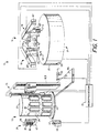
- FIG. 1 there is shown an embodiment of an automated analytical instrument for measuring a component of interest in a fluid sample, the instrument being constructed according to the teachings of the present invention and represented generally by reference numeral 11.
- Instrument 11 includes an assay module supply apparatus 13 for holding a supply of assay modules, a testing system 14 which includes equipment for testing the fluid sample, an assay module transfer apparatus 15 for transferring an assay module from supply apparatus 13 to testing system 14 and a microprocessor 17 for processing and/or displaying the results obtained by testing system 14 and for controlling the operation of supply apparatus 13, testing system 14.
- testing system 14 includes a pair of fluid dispensing units 19 for dispensing the fluid to be tested, a housing 20 which defines a temperature controlled chamber 21 for use in performing the testing, and a plurality of readout systems 23 for measuring the detectable change which is a function of the component of interest in the fluid sample, it being understood that the number of fluid dispensing units shown and the number of readout systems shown are by way of example only.
- Assay module supply apparatus 13 includes a carousel 27 which is a semi-cylindrically shaped unit having a plurality of rectangularly shaped chambers 29 circumferentially spaced thereon in two rows.
- a carousel 27 which is a semi-cylindrically shaped unit having a plurality of rectangularly shaped chambers 29 circumferentially spaced thereon in two rows.
- another such semi-cylindrically shaped carousel may be provided and further that these units may include any number of rows of chambers.
- Supply apparatus 13 also includes a plurality of magazines 31, each magazine 31 being removably snap-locked into one of the chambers 29 by means of inwardly-biasing tabs 33 formed on carousel 27.
- Each magazine 31 comprises a rectangularly shaped, open-faced vessel 35 which is internally subdivided to define a plurality of compartments 37.
- An assay module 39 is removably stored in each compartment 37.
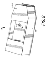
- a perspective view of one of the assay modules 39 is shown in Fig. 2.
- assay module 39 is an elongated boat shaped structure 40 having an inwardly tapered front end 40-1.
- An opening 41 is provided inside assay module 39 to access the reagent-bearing assay element 41-1 contained therein.
- a sheet of foil 42 (shown partially torn away) or other similar material suitable for preventing moisture from entering compartments 37 is preferably sealed over the open face of vessel 35.
- Supply apparatus 13 further includes means for rotating carousel 27 about a vertical axis so that assay modules 39 in different magazines 31 can be accessed by assay module transfer apparatus 15 in the manner to be discussed below.
- the rotating means comprises a rotatably mounted platform 43 on top of which carousel 27 is removably mounted. Platform 43 is turned by means of a motor 45, which is mechanically coupled through a belt 47 to a shaft (not shown) which is fixedly attached to platform 43.
- the rotational position of carousel 27 is controlled by microprocessor 17.
- instrument 11 can be greatly expanded by loading one magazine 31 with assay modules 39 of a single specificity and others of the magazines with assay modules which are specific for other components of interest.
- Chamber 21 which may be any type of construction, includes a rotatably mounted turntable 51 driven by a motor 50.
- Turntable 51 includes a plurality of circumferentially spaced berths 52 each of which is adapted to receive an assay module 39.
- Assay modules 39 are loaded onto berths 52 using an automated shuttle mechanism 53.
- the shuttle mechanism 53 which in this preferred embodiment is located within chamber 21 includes a platform onto which the assay module is deposited by the transfer apparatus 15 through an entry port 55.
- the shuttle mechanism includes a slidably mounted element (not shown) which transports the assay module from the platform and positions it in a berth 52 on the turntable.
- the platform can be pivotally mounted so as to permit assay modules to be discarded after use.
- the used assay module can be removed from the turntable at the same location where it was deposited on the turntable and dropped into a receptacle located below the platform.
- Shuttle mechanism 53 is powered by a motor (not shown).
- Chamber 21 also includes a pair of metering stations 56-1 and 56-2, which are disposed radially outwardly a short distance from turntable 51.
- assay modules 39 disposed at metering stations 56 receive quantities of the fluid sample from fluid dispensing units 19 through a pair of openings 57-1 and 57-2 formed in the top wall of chamber 21.
- a pair of automated shuttle mechanisms 58-1 and 58-2 are used to transport assay modules 39 back and forth between turntable 51 and metering stations 56-1 and 56-2, respectively.
- Chamber 21 further includes a plurality of read stations 59-1 through 59-3, which are also disposed radially a short distance from turntable 51. As will be seen below, analysis of the fluid samples is performed at read stations 59 using readout systems, one system 23 being at each read station 59. A plurality of automated shuttle mechanisms 61-1 through 61-3 are used to transport assay modules 39 back and forth between turntable 51 and read stations 59-1 through 59-3, respectively.
- an assay module is deposited into passageway 117 (shown in Fig. 7) through inlet 113 by the finger elements 121 of the pulling mechanism.
- the pusher element 133 is retracted below passageway 117.
- the pusher element 133 pivots upwardly to engage the back wall of the assay module and pushes the module through the passageway and through outlet 115.
- pusher element 133 pivots so as to increase the stroke, or the distance traveled, of the assay module.
- the assay module is desirably able to travel a greater linear distance than the yoke 137.
- each fluid dispensing unit 19 is seen to include a pipette 65 which is operated by a motor-driven pipette assembly 67 which is controlled by microprocessor 17.
- each pipette 65 picks up a disposable pipette tip 70 from a supply table 71, withdraws a quantity of the fluid sample from a fluid sample cup 74 held in a fluid sample cup holder 75 which travels back and forth between the pipettes 65 and then dispenses the quantities of the fluid sample into assay modules 39 located at metering stations 56.
- a detectable change is effected corresponding to the presence of a component of interest in the sample fluid.
- the detectable change may be a color change which may be read spectrophotometrically such as with a densitometer or, in an assay method based on fluorescent-labeled species or one which involves the generation of a fluorescent species as a result of a reaction between test reagents, a fluorescent output signal can be generated and read spectrofluorometrically.
- Such detectable changes may be read from above or below the assay module.
- Readout system 23 is shown here below the assay module. The information obtained by readout system 23 is then transmitted to microprocessor 17 for processing, the results of which are displayed on a monitor (not shown) and/or printed out with a printer (also not shown).
- assay module transfer apparatus 15 is seen to include an assay module transfer unit 81, a support assembly 83 upon which assay module transfer unit 81 is slidably mounted and an automated mechanism 85 for moving unit 81 up and down on support assembly 83.
- Support assembly 83 includes a base 84.
- An elongated, vertically disposed supporting frame 87 is fixedly mounted on base 84 and an elongated, vertically extending post 89 is fixedly mounted on frame 87.
- a pair of rods 91-1 and 91-2 are fixedly mounted on opposite sides of post 89.
- Unit 81 is slidably mounted on rods 91-1 and 91-2 through a pair of elements 93-1 and 93-2 which are fixedly mounted on the back surface of a rectangular block 95.
- Block 95 is fixedly mounted on the back surface of a second rectangular block 97, which is fixedly mounted on the back of assay module transfer unit 81.
- Mechanism 85 for moving assay module transfer unit 81 up and down along rods 91 includes a rotatably mounted belt 99 which is driven by a motor 101 and which is mechanically coupled to block 95 through a coupling element 103.
- the operation of motor 101 is controlled by microprocessor 17.
- unit 81 includes a generally rectangular, elongated block 111 having an inlet 113 at one end and an outlet 115 at an opposite end. Inlet 113 and outlet 115 are in communication with each other through a passageway 117.
- An elongated retaining plate 119 which extends from inlet 113 to outlet 115, is fixedly mounted on block 111. As will be seen below, plate 119 helps to retain an assay module within passageway 117 as it is pushed through.
- a generally rectangular guide plate 118 is fixedly secured to block 111 by bolts 120.
- Assay module transfer unit 81 also includes a pulling mechanism which is mounted on block 111 for pulling an assay module 39 from carousel 27 into passageway 117 through inlet 113 and a pushing mechanism which is also mounted on block 111 for pushing the assay module 39 so obtained out of passageway 117 through outlet 115 into testing system 14.
- the pulling mechanism includes a pair of spring biased finger elements 121-1 and 121-2 for engaging an assay module 39 in one of the compartments 37 in one of the magazines 31 in carousel 27 and then extracting the assay module 39 from the compartment.
- Finger elements 121 which are spring biased in an inward direction toward each other are fixedly mounted by any suitable means, not shown, on a U shaped supporting bracket 122 which is fixedly attached to a coupling plate 123.
- Plate 123 is fixedly attached by any suitable means, not shown, to an endless belt 124 which is mounted for movement along a path defined by wheels 125, 126, 127 and 128.
- Belt 124 is driven by a reversible stepping motor 129 whose output shaft 130 is fixedly attached to wheel 125.
- the pulling mechanism also includes an extension plate 131 which is pivotally mounted on guide plate 118 and on retaining plate 119. Extension plate 131 serves as a cutting element for cutting foil 42 which in a preferred embodiment covers the opening of the compartment in the magazine to be accessed by finger elements 121 and also serves to provide a surface over which the assay module moves as it is transported from the magazine into assay module transfer unit 81.
- the pushing mechanism which is adapted to push the assay module from behind out of passageway 117 through outlet 115 includes a pusher element 133 having an end 134 which extends into passageway 117.
- Pusher element 133 is pivotally mounted by a pin 135 to a yoke 137, which is slidably mounted in a track 138 formed in block 111 below passageway 117 .
- An endless bolt 140 is fixedly coupled to yoke 137 and moves yoke 137 back and forth along track 138.
- Microprocessor 17 controls the operation of motor 141 and, hence, the direction in which yoke 137 moves.
- a pair of pins 139-1 and 139-2 are fixedly mounted on pusher element 133 and travel in a pair of grooves 142-1 and 142-2, respectively, formed on guide plate 118. As can be seen, the shape and disposition of grooves 142 on plate 118 causes pusher element 133 to pivot upwardly as it approaches outlet 115.
- microprocessor 17 To use instrument 11, the operator deposits a fluid sample into one or more of the fluid sample cups 74 in fluid sample cup holder 75 and directs microprocessor 17 to assay for a particular component of the fluid sample. Microprocessor 17 then directs motor 45 to rotate platform 43 so that a magazine 31 containing assay modules 39 specific for the component of interest is aligned with assay module transfer apparatus 15. In addition, microprocessor 17 directs motor assembly 101 to position unit 81 vertically so that it is aligned with a compartment 37 of the magazine 31 containing an assay module 39.
- microprocessor 17 next actuates motor 129 to cause bracket 122 carrying finger elements 121 to move in the direction of that compartment.
- cutting element 131 is pivoted downwardly and outwardly, cutting into the foil sheet covering the compartment and exposing the assay module 39 contained therein.
- fingers 121-1 and 121-2 move across the assay module, they will first be spread apart and then will engage the assay module from the rear.
- Microprocessor 17 then causes motor 129 to reverse direction, causing the assay module to be pulled out of the magazine 31 and into block 111 through inlet 113.
- microprocessor 17 turns off motor 129 and turns on motor 141.
- Motor 141 causes yoke 137 to slide across track 138, which in turn causes pusher element 133 to push assay module 39 through outlet 115 into shuttle mechanism 53 of testing system 14.
- Microprocessor 17 then directs motor 141 to reverse direction, causing yoke 137 to slide back to its original position on track 138.
Landscapes
- Physics & Mathematics (AREA)
- Health & Medical Sciences (AREA)
- Life Sciences & Earth Sciences (AREA)
- Chemical & Material Sciences (AREA)
- Analytical Chemistry (AREA)
- Biochemistry (AREA)
- General Health & Medical Sciences (AREA)
- General Physics & Mathematics (AREA)
- Immunology (AREA)
- Pathology (AREA)
- Automatic Analysis And Handling Materials Therefor (AREA)
- Sampling And Sample Adjustment (AREA)
- Investigating Or Analysing Biological Materials (AREA)
Abstract
Description
- The present invention relates generally to automated analytical instruments for use in conducting assays for a component of interest in a fluid sample and more particularly to automated analytical instruments which use assay modules for conducting assays for a component of interest in a fluid sample.
- In recent years, a number of automated instruments have been developed for carrying out quantitative chemical and immunochemical analyses of fluid samples. As is known in the art, such instruments may be used to test various fluids for substances of interest, for example, to find evidence of disease, to monitor therapeutic drug levels, and the like. Typically, such automated analytical instruments utilize either liquid reagents or dry reagents to assay for a substance of interest. Various different types of assay devices are known for use in such automated instruments including, for example, dry, thin-film multilayer assay elements which are typically mounted in an assay module and capillary assay devices.
- Generally speaking, the testing system portion of automated analytical instruments which use assay modules to test for a substance of interest typically includes a fluid dispensing system for metering out a quantity of the fluid sample to be analyzed to an assay module, a temperature controlled chamber for holding the assay modules at the appropriate temperature to allow the reaction to take place, an analyzing system for measuring a detectable change brought about by the presence of the substance of interest in the fluid sample and some mechanism for conveying the assay module to each of the foregoing components in the proper order.
- The assay modules may be provided by various techniques. In U.S. Pat. No. 4,152,390, there is described an automated analytical instrument which includes, in addition to the testing system, a supply unit for holding a plurality of assay modules and a transfer apparatus for transferring an assay module from the supply unit to the testing system. The assay modules are stacked in containers, which may be received in a nest of the analyzing apparatus with a spring biased plunger arranged to enter the container through an opening. The plunger engages a movable element located in the container behind the stack of modules to urge the top module forwardly towards the testing system portion of the instrument. In another type of automated analytical instrument an assay module to be used is manually loaded into an assay module transfer device. The assay module is then transferred to the test system.
- As can readily be appreciated, automated analytical instruments which include an automated mechanism for transferring assay modules stored within the instrument to the testing system are desirable since they do not require an operator to manually feed assay modules, one at a time, into the testing system.
- It is an object of the present invention to provide a new and improved automated analytical instrument.
- It is another object of this invention to provide an automated analytical instrument which includes a new and novel arrangement for transferring an assay module from an assay module supply apparatus to the testing system portion of the instrument.
- It is still another object of this invention to provide an automated analytical instrument using assay modules wherein the assay modules are stored for use in magazines which are subdivided to form compartments, each compartment being adapted to hold a single assay module.
- Additional objects, as well as features and advantages, of the present invention will be set forth in part in the description which follows, and in part will be obvious from the description or may be learned by practice of the invention. The objects, features, and advantages of the present invention may be realized and attained by means of the instrumentalities and combinations particularly pointed out in the appended claims.
- Accordingly, to achieve the foregoing objects and in accordance with the purpose of the present invention as broadly set forth and embodied herein, an automated analytical instrument for use in conducting assays for a component of interest in a fluid sample is provided by the device defined in Claim 1.
- The accompanying drawings, which are hereby incorporated into and constitute a part of this specification, illustrate the preferred embodiments of the invention and, together with the description, serve to explain the principles of the invention. In these drawings wherein like reference numerals represent like parts:
- Fig. 1 is a perspective view partially exploded of one embodiment of an automated analytical instrument for measuring a component of interest in a fluid sample, the instrument being constructed according to the teachings of the present invention;
- Fig. 2 is an enlarged perspective view of one type of the assay modules which maybe used in the automated instrument of the invention;
- Fig. 3 is an enlarged perspective view of the temperature controlled chamber shown in Fig. 1 with the housing removed;
- Fig. 4 is a side view of the assay module transfer apparatus shown in Fig. 1;
- Fig. 5 is a top view of the assay module transfer apparatus shown in Fig. 4;
- Fig. 6 is a back view of the assay module transfer unit shown in Fig. 4
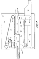
- Fig. 7 is a front view of the assay module transfer unit shown in Fig. 1 with the guide plate removed;
- Fig. 8 is a perspective view from the left side of the assay module transfer unit shown in Fig. 4; and
- Fig. 9 is a back view of the guide plate in the assay module transfor unit shown in Fig. 4.
- Referring now to Fig. 1, there is shown an embodiment of an automated analytical instrument for measuring a component of interest in a fluid sample, the instrument being constructed according to the teachings of the present invention and represented generally by reference numeral 11.
- Instrument 11 includes an assay
module supply apparatus 13 for holding a supply of assay modules, atesting system 14 which includes equipment for testing the fluid sample, an assaymodule transfer apparatus 15 for transferring an assay module fromsupply apparatus 13 to testingsystem 14 and amicroprocessor 17 for processing and/or displaying the results obtained bytesting system 14 and for controlling the operation ofsupply apparatus 13,testing system 14. In this preferredembodiment testing system 14 includes a pair offluid dispensing units 19 for dispensing the fluid to be tested, ahousing 20 which defines a temperature controlledchamber 21 for use in performing the testing, and a plurality of readout systems 23 for measuring the detectable change which is a function of the component of interest in the fluid sample, it being understood that the number of fluid dispensing units shown and the number of readout systems shown are by way of example only. - Assay
module supply apparatus 13 includes acarousel 27 which is a semi-cylindrically shaped unit having a plurality of rectangularlyshaped chambers 29 circumferentially spaced thereon in two rows. Of course, it is apparent that another such semi-cylindrically shaped carousel may be provided and further that these units may include any number of rows of chambers. -
Supply apparatus 13 also includes a plurality ofmagazines 31, eachmagazine 31 being removably snap-locked into one of thechambers 29 by means of inwardly-biasingtabs 33 formed oncarousel 27. Eachmagazine 31 comprises a rectangularly shaped, open-faced vessel 35 which is internally subdivided to define a plurality ofcompartments 37. As can be seen, when mounted incarousel 27 thecompartments 37 within each magazine are disposed in vertical rows. Anassay module 39 is removably stored in eachcompartment 37. A perspective view of one of theassay modules 39 is shown in Fig. 2. As can be seen,assay module 39 is an elongated boat shapedstructure 40 having an inwardly tapered front end 40-1. Anopening 41 is provided insideassay module 39 to access the reagent-bearing assay element 41-1 contained therein. A sheet of foil 42 (shown partially torn away) or other similar material suitable for preventing moisture from enteringcompartments 37 is preferably sealed over the open face ofvessel 35. -
Supply apparatus 13 further includes means for rotatingcarousel 27 about a vertical axis so thatassay modules 39 indifferent magazines 31 can be accessed by assaymodule transfer apparatus 15 in the manner to be discussed below. In the embodiment shown, the rotating means comprises a rotatably mountedplatform 43 on top of whichcarousel 27 is removably mounted.Platform 43 is turned by means of amotor 45, which is mechanically coupled through abelt 47 to a shaft (not shown) which is fixedly attached toplatform 43. The rotational position ofcarousel 27 is controlled bymicroprocessor 17. - As can readily be appreciated, the capabilities of instrument 11 can be greatly expanded by loading one
magazine 31 withassay modules 39 of a single specificity and others of the magazines with assay modules which are specific for other components of interest. By rotatingcarousel 27 such that anassay module 39 of a desired specificity can be positioned for removal by assaymodule transfer apparatus 15 it is possible to carry out assays for the various components automatically as desired. - Referring now to Fig. 3, temperature controlled
chamber 21 is shown in greater detail.Chamber 21, which may be any type of construction, includes a rotatably mountedturntable 51 driven by amotor 50.Turntable 51 includes a plurality of circumferentially spacedberths 52 each of which is adapted to receive anassay module 39. For simplicity, only a few ofberths 52 are shown in Fig. 3.Assay modules 39 are loaded ontoberths 52 using anautomated shuttle mechanism 53. Theshuttle mechanism 53, which in this preferred embodiment is located withinchamber 21 includes a platform onto which the assay module is deposited by thetransfer apparatus 15 through anentry port 55. The shuttle mechanism includes a slidably mounted element (not shown) which transports the assay module from the platform and positions it in aberth 52 on the turntable. The platform can be pivotally mounted so as to permit assay modules to be discarded after use. In such an embodiment the used assay module can be removed from the turntable at the same location where it was deposited on the turntable and dropped into a receptacle located below the platform.Shuttle mechanism 53 is powered by a motor (not shown). -
Chamber 21 also includes a pair of metering stations 56-1 and 56-2, which are disposed radially outwardly a short distance fromturntable 51. In the operation of the system,assay modules 39 disposed at metering stations 56 receive quantities of the fluid sample fromfluid dispensing units 19 through a pair of openings 57-1 and 57-2 formed in the top wall ofchamber 21. A pair of automated shuttle mechanisms 58-1 and 58-2 are used to transportassay modules 39 back and forth betweenturntable 51 and metering stations 56-1 and 56-2, respectively. -
Chamber 21 further includes a plurality of read stations 59-1 through 59-3, which are also disposed radially a short distance fromturntable 51. As will be seen below, analysis of the fluid samples is performed at read stations 59 using readout systems, one system 23 being at each read station 59. A plurality of automated shuttle mechanisms 61-1 through 61-3 are used to transportassay modules 39 back and forth betweenturntable 51 and read stations 59-1 through 59-3, respectively. - Both the rotation of
turntable 51 and the actuation ofautomated shuttle mechanisms 53, 58, and 61 are controlled bymicroprocessor 17. - In operation an assay module is deposited into passageway 117 (shown in Fig. 7) through
inlet 113 by the finger elements 121 of the pulling mechanism. During this step thepusher element 133 is retracted belowpassageway 117. Following the positioning of the assay module inpassageway 117 thepusher element 133 pivots upwardly to engage the back wall of the assay module and pushes the module through the passageway and throughoutlet 115. During the path of travel throughpassageway 117,pusher element 133 pivots so as to increase the stroke, or the distance traveled, of the assay module. Thus, the assay module is desirably able to travel a greater linear distance than theyoke 137. - Referring back to Fig. 1, each
fluid dispensing unit 19 is seen to include apipette 65 which is operated by a motor-drivenpipette assembly 67 which is controlled bymicroprocessor 17. In use, eachpipette 65 picks up adisposable pipette tip 70 from a supply table 71, withdraws a quantity of the fluid sample from afluid sample cup 74 held in a fluidsample cup holder 75 which travels back and forth between thepipettes 65 and then dispenses the quantities of the fluid sample intoassay modules 39 located at metering stations 56. - During the assay procedure, as a result of the reaction(s) or interaction(s) between the sample fluid and the test reagent(s) which take place, a detectable change is effected corresponding to the presence of a component of interest in the sample fluid. The detectable change may be a color change which may be read spectrophotometrically such as with a densitometer or, in an assay method based on fluorescent-labeled species or one which involves the generation of a fluorescent species as a result of a reaction between test reagents, a fluorescent output signal can be generated and read spectrofluorometrically. Such detectable changes may be read from above or below the assay module. Readout system 23 is shown here below the assay module. The information obtained by readout system 23 is then transmitted to
microprocessor 17 for processing, the results of which are displayed on a monitor (not shown) and/or printed out with a printer (also not shown). - Referring now to Figs. 4 and 5, assay
module transfer apparatus 15 is seen to include an assaymodule transfer unit 81, asupport assembly 83 upon which assaymodule transfer unit 81 is slidably mounted and anautomated mechanism 85 for movingunit 81 up and down onsupport assembly 83. -
Support assembly 83 includes abase 84. An elongated, vertically disposed supportingframe 87 is fixedly mounted onbase 84 and an elongated, vertically extendingpost 89 is fixedly mounted onframe 87. A pair of rods 91-1 and 91-2 are fixedly mounted on opposite sides ofpost 89. -
Unit 81 is slidably mounted on rods 91-1 and 91-2 through a pair of elements 93-1 and 93-2 which are fixedly mounted on the back surface of arectangular block 95.Block 95, in turn, is fixedly mounted on the back surface of a secondrectangular block 97, which is fixedly mounted on the back of assaymodule transfer unit 81. -
Mechanism 85 for moving assaymodule transfer unit 81 up and down along rods 91 includes a rotatably mountedbelt 99 which is driven by amotor 101 and which is mechanically coupled to block 95 through acoupling element 103. The operation ofmotor 101 is controlled bymicroprocessor 17. - Referring now to Figs. 6-9, assay
module transfer unit 81 and component parts thereof are shown in greater detail. As can be seen,unit 81 includes a generally rectangular,elongated block 111 having aninlet 113 at one end and anoutlet 115 at an opposite end.Inlet 113 andoutlet 115 are in communication with each other through apassageway 117. Anelongated retaining plate 119, which extends frominlet 113 tooutlet 115, is fixedly mounted onblock 111. As will be seen below,plate 119 helps to retain an assay module withinpassageway 117 as it is pushed through. A generallyrectangular guide plate 118 is fixedly secured to block 111 bybolts 120. - Assay
module transfer unit 81 also includes a pulling mechanism which is mounted onblock 111 for pulling anassay module 39 fromcarousel 27 intopassageway 117 throughinlet 113 and a pushing mechanism which is also mounted onblock 111 for pushing theassay module 39 so obtained out ofpassageway 117 throughoutlet 115 intotesting system 14. - The pulling mechanism includes a pair of spring biased finger elements 121-1 and 121-2 for engaging an
assay module 39 in one of thecompartments 37 in one of themagazines 31 incarousel 27 and then extracting theassay module 39 from the compartment. Finger elements 121 which are spring biased in an inward direction toward each other are fixedly mounted by any suitable means, not shown, on a U shaped supportingbracket 122 which is fixedly attached to acoupling plate 123.Plate 123 is fixedly attached by any suitable means, not shown, to an endless belt 124 which is mounted for movement along a path defined bywheels reversible stepping motor 129 whoseoutput shaft 130 is fixedly attached towheel 125. Operation of steppingmotor 129 is controlled bymicroprocessor 17. The pulling mechanism also includes anextension plate 131 which is pivotally mounted onguide plate 118 and on retainingplate 119.Extension plate 131 serves as a cutting element for cuttingfoil 42 which in a preferred embodiment covers the opening of the compartment in the magazine to be accessed by finger elements 121 and also serves to provide a surface over which the assay module moves as it is transported from the magazine into assaymodule transfer unit 81. - The pushing mechanism which is adapted to push the assay module from behind out of
passageway 117 throughoutlet 115 includes apusher element 133 having anend 134 which extends intopassageway 117.Pusher element 133 is pivotally mounted by apin 135 to ayoke 137, which is slidably mounted in atrack 138 formed inblock 111 belowpassageway 117 . Anendless bolt 140 is fixedly coupled toyoke 137 and movesyoke 137 back and forth alongtrack 138.Microprocessor 17 controls the operation ofmotor 141 and, hence, the direction in whichyoke 137 moves. A pair of pins 139-1 and 139-2 are fixedly mounted onpusher element 133 and travel in a pair of grooves 142-1 and 142-2, respectively, formed onguide plate 118. As can be seen, the shape and disposition of grooves 142 onplate 118 causespusher element 133 to pivot upwardly as it approachesoutlet 115. - To use instrument 11, the operator deposits a fluid sample into one or more of the fluid sample cups 74 in fluid
sample cup holder 75 and directsmicroprocessor 17 to assay for a particular component of the fluid sample.Microprocessor 17 then directsmotor 45 to rotateplatform 43 so that amagazine 31 containingassay modules 39 specific for the component of interest is aligned with assaymodule transfer apparatus 15. In addition,microprocessor 17 directsmotor assembly 101 to positionunit 81 vertically so that it is aligned with acompartment 37 of themagazine 31 containing anassay module 39. - With
unit 81 thus aligned with onecompartment 37 in onemagazine 31 oncarousel 27,microprocessor 17 next actuates motor 129 to causebracket 122 carrying finger elements 121 to move in the direction of that compartment. At the sametime cutting element 131 is pivoted downwardly and outwardly, cutting into the foil sheet covering the compartment and exposing theassay module 39 contained therein. As fingers 121-1 and 121-2 move across the assay module, they will first be spread apart and then will engage the assay module from the rear.Microprocessor 17 then causesmotor 129 to reverse direction, causing the assay module to be pulled out of themagazine 31 and intoblock 111 throughinlet 113. - Once
assay module 39 is disposed inpassageway 117,microprocessor 17 turns offmotor 129 and turns onmotor 141.Motor 141 causesyoke 137 to slide acrosstrack 138, which in turn causespusher element 133 to pushassay module 39 throughoutlet 115 intoshuttle mechanism 53 oftesting system 14.Microprocessor 17 then directsmotor 141 to reverse direction, causingyoke 137 to slide back to its original position ontrack 138.
Claims (10)
- An automated analytical instrument (11) for use in conducting assays for a component of interest in a fluid sample, said automated analytical instrument (11) comprising:a. an assay module supply apparatus (13) for holding a supply of assay modules (39), said assay module supply apparatus (13) comprising at least one magazine (31) having a plurality of compartments (37) arranged in a vertical row, each said compartment (37) adapted to hold an assay module (39);b. a testing system (14) having equipment for testing of a fluid sample using an assay module (39), andc. an assay module transfer apparatus (15) for transferring an assay module (39) from said assay module supply apparatus (13) to said testing system (14), said assay module transfer apparatus (15) comprising a support structure (83) extending vertically upward and an assay module transfer unit (81), said assay module transfer unit (81) having means for pulling an assay module (39) out from a compartment (37) of said magazine (31) and means for pushing an assay module so obtained into said testing system (14), wherein said assay module transfer unit (81) is slidably mounted on said support structure (83) for vertical movement along said support structure (83).
- The automated analytical instrument (11) of claim 1 and wherein said assay module transfer unit (81) includes an elongated block (111) and said pulling means and said pushing means are mounted on said elongated block (111).
- The automated analytical instrument (11) of claim 2 and wherein said pulling means comprises a pair of gripping fingers (121) for gripping an assay module (39).
- The automated analytical instrument (11) of claim 3 and wherein said pulling means further comprises a belt (124) rotatably mounted on said elongated block (111), a motor (129) for driving said belt (124) and a plate (131) for coupling the belt (124) to the finger elements (121).
- The automated analytical instrument (11) of claim 4 and wherein the motor (129) is a reversible motor.
- The automated analytical instrument (11) of claim 2 and wherein the pushing means includes a pushing element (133) for pushing said assay module (39) out of said assay module transfer unit (81).
- The automated analytical instrument (11) of claim 6 and wherein said pushing means further includes a yoke (137) slidably mounted on said elongated block (111) and said pushing element (133) is pivotally mounted on said yoke (137).
- The automated analytical instrument (11) of claim 7 and wherein said pushing element (133) further includes a belt (140) rotably mounted on said elongated block (111) and a motor (141) for driving said belt (140) and wherein said yoke (137) is attached to said belt (140).
- The automated analytical instrument (11) of claim 8 and further including a motor (101) coupled to said assay module transfer unit (81) for moving said assay module transfer unit (81) vertically along said support structure (83).
- The automated analytical instrument (11) of claim 1 and wherein said assay module supply apparatus (13) comprises a carousel (27), a mechanism for turning said carousel (27) and a plurality of said magazines (31) removably mounted on said carousel (27).
Applications Claiming Priority (3)
| Application Number | Priority Date | Filing Date | Title |
|---|---|---|---|
| US73205391A | 1991-07-18 | 1991-07-18 | |
| US732053 | 1991-07-18 | ||
| PCT/US1992/005192 WO1993002364A1 (en) | 1991-07-18 | 1992-06-16 | Assay module transfer apparatus for use in an automated analytical instrument |
Publications (2)
| Publication Number | Publication Date |
|---|---|
| EP0549759A1 EP0549759A1 (en) | 1993-07-07 |
| EP0549759B1 true EP0549759B1 (en) | 1996-02-07 |
Family
ID=24942006
Family Applications (1)
| Application Number | Title | Priority Date | Filing Date |
|---|---|---|---|
| EP92914578A Expired - Lifetime EP0549759B1 (en) | 1991-07-18 | 1992-06-16 | Assay module transfer apparatus for use in an automated analytical instrument |
Country Status (9)
| Country | Link |
|---|---|
| EP (1) | EP0549759B1 (en) |
| JP (1) | JP2538186B2 (en) |
| AT (1) | ATE134042T1 (en) |
| AU (1) | AU652278B2 (en) |
| CA (1) | CA2087713A1 (en) |
| DE (1) | DE69208241T2 (en) |
| DK (1) | DK0549759T3 (en) |
| ES (1) | ES2086126T3 (en) |
| WO (1) | WO1993002364A1 (en) |
Families Citing this family (9)
| Publication number | Priority date | Publication date | Assignee | Title |
|---|---|---|---|---|
| US5332549A (en) * | 1992-07-01 | 1994-07-26 | Pb Diagnostic Systems, Inc. | Assay module transport apparatus for use in an automated analytical instrument |
| DE59410388D1 (en) * | 1993-04-23 | 2004-10-21 | Roche Diagnostics Gmbh | Floppy disk with test elements arranged in a circle |
| SE9602298D0 (en) * | 1996-06-11 | 1996-06-11 | Siemens Elema Ab | Arrangement for analyzing body fluids |
| ID23862A (en) * | 1998-02-20 | 2000-05-25 | Scil Diagnotics Gmbh | ANALYSIS SYSTEM |
| US6881579B2 (en) * | 2001-07-30 | 2005-04-19 | Agilent Technologies, Inc. | Sample processing apparatus and methods |
| FR2873447B1 (en) | 2004-07-23 | 2007-09-28 | Alain Michel Rousseau | MULTI-DISCIPLINARY AUTOMATIC ANALYZER FOR IN VITRO DIAGNOSIS |
| FR2896589B1 (en) | 2006-01-25 | 2008-04-25 | Biocode Hycel France Sa Sa | MULTIPURPOSE ANALYSIS CUP |
| EP2463030A1 (en) * | 2010-12-08 | 2012-06-13 | F. Hoffmann-La Roche AG | Storage assembly for providing reagent carriers for being processed in an analyzing system |
| RU2762147C2 (en) * | 2016-11-18 | 2021-12-16 | Сифейд | System and method for processing matrix of sample processing modules |
Family Cites Families (5)
| Publication number | Priority date | Publication date | Assignee | Title |
|---|---|---|---|---|
| US4224032A (en) * | 1976-12-17 | 1980-09-23 | Eastman Kodak Company | Method and apparatus for chemical analysis |
| CA1099951A (en) * | 1976-12-17 | 1981-04-28 | Clyde P. Glover | Automatic chemical analysis of biological fluids |
| US4298571A (en) * | 1976-12-17 | 1981-11-03 | Eastman Kodak Company | Incubator including cover means for an analysis slide |
| US4678752A (en) * | 1985-11-18 | 1987-07-07 | Becton, Dickinson And Company | Automatic random access analyzer |
| JPS6456706A (en) * | 1987-08-27 | 1989-03-03 | Nippon Soda Co | Curable resin, production thereof and curable resin composition therefrom |
-
1992
- 1992-06-16 AT AT92914578T patent/ATE134042T1/en not_active IP Right Cessation
- 1992-06-16 AU AU22527/92A patent/AU652278B2/en not_active Ceased
- 1992-06-16 EP EP92914578A patent/EP0549759B1/en not_active Expired - Lifetime
- 1992-06-16 JP JP5502793A patent/JP2538186B2/en not_active Expired - Lifetime
- 1992-06-16 WO PCT/US1992/005192 patent/WO1993002364A1/en not_active Ceased
- 1992-06-16 ES ES92914578T patent/ES2086126T3/en not_active Expired - Lifetime
- 1992-06-16 DE DE69208241T patent/DE69208241T2/en not_active Expired - Fee Related
- 1992-06-16 CA CA002087713A patent/CA2087713A1/en not_active Abandoned
- 1992-06-16 DK DK92914578.7T patent/DK0549759T3/en active
Also Published As
| Publication number | Publication date |
|---|---|
| AU652278B2 (en) | 1994-08-18 |
| WO1993002364A1 (en) | 1993-02-04 |
| DE69208241D1 (en) | 1996-03-21 |
| ATE134042T1 (en) | 1996-02-15 |
| AU2252792A (en) | 1993-02-23 |
| ES2086126T3 (en) | 1996-06-16 |
| JP2538186B2 (en) | 1996-09-25 |
| EP0549759A1 (en) | 1993-07-07 |
| CA2087713A1 (en) | 1993-01-19 |
| JPH06501778A (en) | 1994-02-24 |
| DK0549759T3 (en) | 1996-03-11 |
| DE69208241T2 (en) | 1996-07-18 |
Similar Documents
| Publication | Publication Date | Title |
|---|---|---|
| AU671663B2 (en) | Assay module transport apparatus for use in an automated analytical instrument | |
| US4152390A (en) | Chemical analyzer | |
| US5518688A (en) | Automated analytical instrument having a fluid sample holding tray transport assembly | |
| EP0223002B1 (en) | Automatic random access analyzer | |
| EP1465728B1 (en) | Stackable aliquot vessel array | |
| CA1217790A (en) | Method and apparatus for storing and dispensing analysis slides | |
| US4224032A (en) | Method and apparatus for chemical analysis | |
| US7842237B1 (en) | Automatic analyzer and rack transfer device | |
| CA1099951A (en) | Automatic chemical analysis of biological fluids | |
| US5055262A (en) | Automatic cuvette loading apparatus | |
| JPS6125100B2 (en) | ||
| MXPA06000249A (en) | Automated multi-detector analyzer. | |
| US6881380B1 (en) | Cup handling subsystem for an automated clinical chemistry analyzer system | |
| AU652278B2 (en) | Assay module transfer apparatus for use in an automated analytical instrument | |
| JP2754110B2 (en) | Biochemical analyzer | |
| JPH0365502B2 (en) | ||
| JPH06242122A (en) | Biochemical analyzer | |
| JPH10253589A (en) | Electrophoretic system |
Legal Events
| Date | Code | Title | Description |
|---|---|---|---|
| PUAI | Public reference made under article 153(3) epc to a published international application that has entered the european phase |
Free format text: ORIGINAL CODE: 0009012 |
|
| AK | Designated contracting states |
Kind code of ref document: A1 Designated state(s): AT BE CH DE DK ES FR GB GR IT LI LU NL SE |
|
| 17P | Request for examination filed |
Effective date: 19930716 |
|
| 17Q | First examination report despatched |
Effective date: 19940824 |
|
| RAP1 | Party data changed (applicant data changed or rights of an application transferred) |
Owner name: BEHRING DIAGNOSTICS INC. |
|
| GRAA | (expected) grant |
Free format text: ORIGINAL CODE: 0009210 |
|
| AK | Designated contracting states |
Kind code of ref document: B1 Designated state(s): AT BE CH DE DK ES FR GB GR IT LI LU NL SE |
|
| PG25 | Lapsed in a contracting state [announced via postgrant information from national office to epo] |
Ref country code: GR Free format text: LAPSE BECAUSE OF FAILURE TO SUBMIT A TRANSLATION OF THE DESCRIPTION OR TO PAY THE FEE WITHIN THE PRESCRIBED TIME-LIMIT Effective date: 19960207 |
|
| REF | Corresponds to: |
Ref document number: 134042 Country of ref document: AT Date of ref document: 19960215 Kind code of ref document: T |
|
| ET | Fr: translation filed | ||
| REG | Reference to a national code |
Ref country code: DK Ref legal event code: T3 |
|
| REF | Corresponds to: |
Ref document number: 69208241 Country of ref document: DE Date of ref document: 19960321 |
|
| REG | Reference to a national code |
Ref country code: CH Ref legal event code: NV Representative=s name: A. BRAUN, BRAUN, HERITIER, ESCHMANN AG PATENTANWAE |
|
| ITF | It: translation for a ep patent filed | ||
| REG | Reference to a national code |
Ref country code: ES Ref legal event code: FG2A Ref document number: 2086126 Country of ref document: ES Kind code of ref document: T3 |
|
| PLBE | No opposition filed within time limit |
Free format text: ORIGINAL CODE: 0009261 |
|
| STAA | Information on the status of an ep patent application or granted ep patent |
Free format text: STATUS: NO OPPOSITION FILED WITHIN TIME LIMIT |
|
| 26N | No opposition filed | ||
| PGFP | Annual fee paid to national office [announced via postgrant information from national office to epo] |
Ref country code: DK Payment date: 19980320 Year of fee payment: 7 |
|
| PGFP | Annual fee paid to national office [announced via postgrant information from national office to epo] |
Ref country code: NL Payment date: 19980324 Year of fee payment: 7 |
|
| PGFP | Annual fee paid to national office [announced via postgrant information from national office to epo] |
Ref country code: LU Payment date: 19980417 Year of fee payment: 7 |
|
| PGFP | Annual fee paid to national office [announced via postgrant information from national office to epo] |
Ref country code: GB Payment date: 19980505 Year of fee payment: 7 |
|
| PGFP | Annual fee paid to national office [announced via postgrant information from national office to epo] |
Ref country code: AT Payment date: 19980507 Year of fee payment: 7 |
|
| PGFP | Annual fee paid to national office [announced via postgrant information from national office to epo] |
Ref country code: SE Payment date: 19980603 Year of fee payment: 7 Ref country code: FR Payment date: 19980603 Year of fee payment: 7 |
|
| PGFP | Annual fee paid to national office [announced via postgrant information from national office to epo] |
Ref country code: ES Payment date: 19980618 Year of fee payment: 7 |
|
| PGFP | Annual fee paid to national office [announced via postgrant information from national office to epo] |
Ref country code: DE Payment date: 19980625 Year of fee payment: 7 |
|
| PGFP | Annual fee paid to national office [announced via postgrant information from national office to epo] |
Ref country code: CH Payment date: 19980708 Year of fee payment: 7 |
|
| PGFP | Annual fee paid to national office [announced via postgrant information from national office to epo] |
Ref country code: BE Payment date: 19980710 Year of fee payment: 7 |
|
| PG25 | Lapsed in a contracting state [announced via postgrant information from national office to epo] |
Ref country code: LU Free format text: LAPSE BECAUSE OF NON-PAYMENT OF DUE FEES Effective date: 19990616 Ref country code: GB Free format text: LAPSE BECAUSE OF NON-PAYMENT OF DUE FEES Effective date: 19990616 Ref country code: DK Free format text: LAPSE BECAUSE OF NON-PAYMENT OF DUE FEES Effective date: 19990616 Ref country code: AT Free format text: LAPSE BECAUSE OF NON-PAYMENT OF DUE FEES Effective date: 19990616 |
|
| PG25 | Lapsed in a contracting state [announced via postgrant information from national office to epo] |
Ref country code: ES Free format text: LAPSE BECAUSE OF NON-PAYMENT OF DUE FEES Effective date: 19990617 |
|
| PG25 | Lapsed in a contracting state [announced via postgrant information from national office to epo] |
Ref country code: SE Free format text: THE PATENT HAS BEEN ANNULLED BY A DECISION OF A NATIONAL AUTHORITY Effective date: 19990629 |
|
| PG25 | Lapsed in a contracting state [announced via postgrant information from national office to epo] |
Ref country code: LI Free format text: LAPSE BECAUSE OF NON-PAYMENT OF DUE FEES Effective date: 19990630 Ref country code: FR Free format text: THE PATENT HAS BEEN ANNULLED BY A DECISION OF A NATIONAL AUTHORITY Effective date: 19990630 Ref country code: CH Free format text: LAPSE BECAUSE OF NON-PAYMENT OF DUE FEES Effective date: 19990630 Ref country code: BE Free format text: LAPSE BECAUSE OF NON-PAYMENT OF DUE FEES Effective date: 19990630 |
|
| BERE | Be: lapsed |
Owner name: BEHRING DIAGNOSTICS INC. Effective date: 19990630 |
|
| PG25 | Lapsed in a contracting state [announced via postgrant information from national office to epo] |
Ref country code: NL Free format text: LAPSE BECAUSE OF NON-PAYMENT OF DUE FEES Effective date: 20000101 |
|
| GBPC | Gb: european patent ceased through non-payment of renewal fee |
Effective date: 19990616 |
|
| REG | Reference to a national code |
Ref country code: CH Ref legal event code: PL |
|
| EUG | Se: european patent has lapsed |
Ref document number: 92914578.7 |
|
| NLV4 | Nl: lapsed or anulled due to non-payment of the annual fee |
Effective date: 20000101 |
|
| REG | Reference to a national code |
Ref country code: DK Ref legal event code: EBP |
|
| PG25 | Lapsed in a contracting state [announced via postgrant information from national office to epo] |
Ref country code: DE Free format text: LAPSE BECAUSE OF NON-PAYMENT OF DUE FEES Effective date: 20000503 |
|
| REG | Reference to a national code |
Ref country code: FR Ref legal event code: ST |
|
| REG | Reference to a national code |
Ref country code: ES Ref legal event code: FD2A Effective date: 20010503 |
|
| PG25 | Lapsed in a contracting state [announced via postgrant information from national office to epo] |
Ref country code: IT Free format text: LAPSE BECAUSE OF NON-PAYMENT OF DUE FEES;WARNING: LAPSES OF ITALIAN PATENTS WITH EFFECTIVE DATE BEFORE 2007 MAY HAVE OCCURRED AT ANY TIME BEFORE 2007. THE CORRECT EFFECTIVE DATE MAY BE DIFFERENT FROM THE ONE RECORDED. Effective date: 20050616 |