EP0549698B1 - Catalytic production of lactide directly from lactic acid - Google Patents
Catalytic production of lactide directly from lactic acid Download PDFInfo
- Publication number
- EP0549698B1 EP0549698B1 EP91917419A EP91917419A EP0549698B1 EP 0549698 B1 EP0549698 B1 EP 0549698B1 EP 91917419 A EP91917419 A EP 91917419A EP 91917419 A EP91917419 A EP 91917419A EP 0549698 B1 EP0549698 B1 EP 0549698B1
- Authority
- EP
- European Patent Office
- Prior art keywords
- lactic acid
- lactide
- feed
- aqueous lactic
- vapor phase
- Prior art date
- Legal status (The legal status is an assumption and is not a legal conclusion. Google has not performed a legal analysis and makes no representation as to the accuracy of the status listed.)
- Expired - Lifetime
Links
- JVTAAEKCZFNVCJ-UHFFFAOYSA-N lactic acid Chemical compound CC(O)C(O)=O JVTAAEKCZFNVCJ-UHFFFAOYSA-N 0.000 title claims abstract description 278
- 235000014655 lactic acid Nutrition 0.000 title claims abstract description 138
- 239000004310 lactic acid Substances 0.000 title claims abstract description 137
- JJTUDXZGHPGLLC-UHFFFAOYSA-N lactide Chemical compound CC1OC(=O)C(C)OC1=O JJTUDXZGHPGLLC-UHFFFAOYSA-N 0.000 title claims abstract description 83
- 238000004519 manufacturing process Methods 0.000 title description 15
- 230000003197 catalytic effect Effects 0.000 title description 4
- 239000003054 catalyst Substances 0.000 claims abstract description 70
- 238000000034 method Methods 0.000 claims abstract description 50
- 238000006243 chemical reaction Methods 0.000 claims abstract description 47
- XLYOFNOQVPJJNP-UHFFFAOYSA-N water Substances O XLYOFNOQVPJJNP-UHFFFAOYSA-N 0.000 claims abstract description 43
- 239000012808 vapor phase Substances 0.000 claims abstract description 27
- PNEYBMLMFCGWSK-UHFFFAOYSA-N aluminium oxide Inorganic materials [O-2].[O-2].[O-2].[Al+3].[Al+3] PNEYBMLMFCGWSK-UHFFFAOYSA-N 0.000 claims abstract description 21
- 239000000706 filtrate Substances 0.000 claims abstract description 19
- 238000009834 vaporization Methods 0.000 claims abstract description 19
- 230000008016 vaporization Effects 0.000 claims abstract description 19
- 125000004122 cyclic group Chemical class 0.000 claims abstract description 10
- 238000000926 separation method Methods 0.000 claims abstract description 8
- IJGRMHOSHXDMSA-UHFFFAOYSA-N Atomic nitrogen Chemical compound N#N IJGRMHOSHXDMSA-UHFFFAOYSA-N 0.000 claims description 36
- VYPSYNLAJGMNEJ-UHFFFAOYSA-N Silicium dioxide Chemical compound O=[Si]=O VYPSYNLAJGMNEJ-UHFFFAOYSA-N 0.000 claims description 24
- 229910052757 nitrogen Inorganic materials 0.000 claims description 18
- 239000012159 carrier gas Substances 0.000 claims description 13
- 239000000377 silicon dioxide Substances 0.000 claims description 9
- 239000007789 gas Substances 0.000 claims description 6
- 238000004821 distillation Methods 0.000 claims description 5
- 239000010457 zeolite Substances 0.000 claims description 2
- 229910021536 Zeolite Inorganic materials 0.000 claims 1
- 239000012141 concentrate Substances 0.000 claims 1
- HNPSIPDUKPIQMN-UHFFFAOYSA-N dioxosilane;oxo(oxoalumanyloxy)alumane Chemical compound O=[Si]=O.O=[Al]O[Al]=O HNPSIPDUKPIQMN-UHFFFAOYSA-N 0.000 claims 1
- 239000000047 product Substances 0.000 abstract description 36
- 238000011084 recovery Methods 0.000 abstract description 10
- 239000007787 solid Substances 0.000 abstract description 6
- UGFAIRIUMAVXCW-UHFFFAOYSA-N Carbon monoxide Chemical compound [O+]#[C-] UGFAIRIUMAVXCW-UHFFFAOYSA-N 0.000 description 30
- 229910002091 carbon monoxide Inorganic materials 0.000 description 30
- 239000000463 material Substances 0.000 description 17
- YMWUJEATGCHHMB-UHFFFAOYSA-N Dichloromethane Chemical compound ClCCl YMWUJEATGCHHMB-UHFFFAOYSA-N 0.000 description 12
- 230000015572 biosynthetic process Effects 0.000 description 12
- 239000011521 glass Substances 0.000 description 12
- JVTAAEKCZFNVCJ-REOHCLBHSA-N L-lactic acid Chemical compound C[C@H](O)C(O)=O JVTAAEKCZFNVCJ-REOHCLBHSA-N 0.000 description 10
- 239000000203 mixture Substances 0.000 description 10
- 239000011324 bead Substances 0.000 description 9
- 230000007062 hydrolysis Effects 0.000 description 9
- 238000006460 hydrolysis reaction Methods 0.000 description 9
- JJTUDXZGHPGLLC-IMJSIDKUSA-N 4511-42-6 Chemical compound C[C@@H]1OC(=O)[C@H](C)OC1=O JJTUDXZGHPGLLC-IMJSIDKUSA-N 0.000 description 8
- 230000008901 benefit Effects 0.000 description 8
- 239000002253 acid Substances 0.000 description 7
- 239000006227 byproduct Substances 0.000 description 7
- 238000011067 equilibration Methods 0.000 description 7
- 238000011065 in-situ storage Methods 0.000 description 7
- JJTUDXZGHPGLLC-ZXZARUISSA-N (3r,6s)-3,6-dimethyl-1,4-dioxane-2,5-dione Chemical compound C[C@H]1OC(=O)[C@H](C)OC1=O JJTUDXZGHPGLLC-ZXZARUISSA-N 0.000 description 6
- 238000000354 decomposition reaction Methods 0.000 description 6
- 238000010438 heat treatment Methods 0.000 description 6
- 239000007788 liquid Substances 0.000 description 6
- 230000006340 racemization Effects 0.000 description 6
- -1 tin halides Chemical class 0.000 description 6
- 125000004432 carbon atom Chemical group C* 0.000 description 5
- 230000003247 decreasing effect Effects 0.000 description 5
- 230000004584 weight gain Effects 0.000 description 5
- 235000019786 weight gain Nutrition 0.000 description 5
- NBIIXXVUZAFLBC-UHFFFAOYSA-N Phosphoric acid Chemical compound OP(O)(O)=O NBIIXXVUZAFLBC-UHFFFAOYSA-N 0.000 description 4
- 230000001186 cumulative effect Effects 0.000 description 4
- 230000000694 effects Effects 0.000 description 4
- JKQOBWVOAYFWKG-UHFFFAOYSA-N molybdenum trioxide Chemical compound O=[Mo](=O)=O JKQOBWVOAYFWKG-UHFFFAOYSA-N 0.000 description 4
- 239000002245 particle Substances 0.000 description 4
- 150000004996 alkyl benzenes Chemical class 0.000 description 3
- 210000000988 bone and bone Anatomy 0.000 description 3
- 150000002148 esters Chemical class 0.000 description 3
- 229920000642 polymer Polymers 0.000 description 3
- 239000000741 silica gel Substances 0.000 description 3
- 229910002027 silica gel Inorganic materials 0.000 description 3
- DLYUQMMRRRQYAE-UHFFFAOYSA-N tetraphosphorus decaoxide Chemical compound O1P(O2)(=O)OP3(=O)OP1(=O)OP2(=O)O3 DLYUQMMRRRQYAE-UHFFFAOYSA-N 0.000 description 3
- 238000005406 washing Methods 0.000 description 3
- IKHGUXGNUITLKF-UHFFFAOYSA-N Acetaldehyde Chemical compound CC=O IKHGUXGNUITLKF-UHFFFAOYSA-N 0.000 description 2
- CSCPPACGZOOCGX-UHFFFAOYSA-N Acetone Chemical compound CC(C)=O CSCPPACGZOOCGX-UHFFFAOYSA-N 0.000 description 2
- 239000004721 Polyphenylene oxide Substances 0.000 description 2
- ATJFFYVFTNAWJD-UHFFFAOYSA-N Tin Chemical compound [Sn] ATJFFYVFTNAWJD-UHFFFAOYSA-N 0.000 description 2
- IKHGUXGNUITLKF-XPULMUKRSA-N acetaldehyde Chemical compound [14CH]([14CH3])=O IKHGUXGNUITLKF-XPULMUKRSA-N 0.000 description 2
- 230000002378 acidificating effect Effects 0.000 description 2
- 229910052784 alkaline earth metal Inorganic materials 0.000 description 2
- 229940061720 alpha hydroxy acid Drugs 0.000 description 2
- 150000001280 alpha hydroxy acids Chemical class 0.000 description 2
- 229910000147 aluminium phosphate Inorganic materials 0.000 description 2
- 238000013459 approach Methods 0.000 description 2
- 125000004429 atom Chemical group 0.000 description 2
- 229920001400 block copolymer Polymers 0.000 description 2
- 238000009835 boiling Methods 0.000 description 2
- 230000015556 catabolic process Effects 0.000 description 2
- 239000002131 composite material Substances 0.000 description 2
- 238000010276 construction Methods 0.000 description 2
- 238000001816 cooling Methods 0.000 description 2
- 238000006731 degradation reaction Methods 0.000 description 2
- 238000001514 detection method Methods 0.000 description 2
- KWKXNDCHNDYVRT-UHFFFAOYSA-N dodecylbenzene Chemical compound CCCCCCCCCCCCC1=CC=CC=C1 KWKXNDCHNDYVRT-UHFFFAOYSA-N 0.000 description 2
- 239000000284 extract Substances 0.000 description 2
- 238000000605 extraction Methods 0.000 description 2
- 238000001914 filtration Methods 0.000 description 2
- 239000011261 inert gas Substances 0.000 description 2
- 239000003456 ion exchange resin Substances 0.000 description 2
- 229920003303 ion-exchange polymer Polymers 0.000 description 2
- 239000007791 liquid phase Substances 0.000 description 2
- 238000006384 oligomerization reaction Methods 0.000 description 2
- 239000011368 organic material Substances 0.000 description 2
- 229920000570 polyether Polymers 0.000 description 2
- 238000006116 polymerization reaction Methods 0.000 description 2
- 239000000843 powder Substances 0.000 description 2
- 238000011160 research Methods 0.000 description 2
- 238000007363 ring formation reaction Methods 0.000 description 2
- 239000004576 sand Substances 0.000 description 2
- 238000005063 solubilization Methods 0.000 description 2
- 230000007928 solubilization Effects 0.000 description 2
- 238000012360 testing method Methods 0.000 description 2
- MCVUKOYZUCWLQQ-UHFFFAOYSA-N tridecylbenzene Chemical compound CCCCCCCCCCCCCC1=CC=CC=C1 MCVUKOYZUCWLQQ-UHFFFAOYSA-N 0.000 description 2
- 239000013638 trimer Substances 0.000 description 2
- OZZQHCBFUVFZGT-BKLSDQPFSA-N (2s)-2-(2-hydroxypropanoyloxy)propanoic acid Chemical compound CC(O)C(=O)O[C@@H](C)C(O)=O OZZQHCBFUVFZGT-BKLSDQPFSA-N 0.000 description 1
- NWUYHJFMYQTDRP-UHFFFAOYSA-N 1,2-bis(ethenyl)benzene;1-ethenyl-2-ethylbenzene;styrene Chemical compound C=CC1=CC=CC=C1.CCC1=CC=CC=C1C=C.C=CC1=CC=CC=C1C=C NWUYHJFMYQTDRP-UHFFFAOYSA-N 0.000 description 1
- VPVXHAANQNHFSF-UHFFFAOYSA-N 1,4-dioxan-2-one Chemical compound O=C1COCCO1 VPVXHAANQNHFSF-UHFFFAOYSA-N 0.000 description 1
- YZUPZGFPHUVJKC-UHFFFAOYSA-N 1-bromo-2-methoxyethane Chemical compound COCCBr YZUPZGFPHUVJKC-UHFFFAOYSA-N 0.000 description 1
- OZZQHCBFUVFZGT-UHFFFAOYSA-N 2-(2-hydroxypropanoyloxy)propanoic acid Chemical compound CC(O)C(=O)OC(C)C(O)=O OZZQHCBFUVFZGT-UHFFFAOYSA-N 0.000 description 1
- SMZOUWXMTYCWNB-UHFFFAOYSA-N 2-(2-methoxy-5-methylphenyl)ethanamine Chemical compound COC1=CC=C(C)C=C1CCN SMZOUWXMTYCWNB-UHFFFAOYSA-N 0.000 description 1
- NIXOWILDQLNWCW-UHFFFAOYSA-N 2-Propenoic acid Natural products OC(=O)C=C NIXOWILDQLNWCW-UHFFFAOYSA-N 0.000 description 1
- HBAQYPYDRFILMT-UHFFFAOYSA-N 8-[3-(1-cyclopropylpyrazol-4-yl)-1H-pyrazolo[4,3-d]pyrimidin-5-yl]-3-methyl-3,8-diazabicyclo[3.2.1]octan-2-one Chemical class C1(CC1)N1N=CC(=C1)C1=NNC2=C1N=C(N=C2)N1C2C(N(CC1CC2)C)=O HBAQYPYDRFILMT-UHFFFAOYSA-N 0.000 description 1
- HCHKCACWOHOZIP-UHFFFAOYSA-N Zinc Chemical compound [Zn] HCHKCACWOHOZIP-UHFFFAOYSA-N 0.000 description 1
- 239000003513 alkali Substances 0.000 description 1
- 239000003125 aqueous solvent Substances 0.000 description 1
- 230000009286 beneficial effect Effects 0.000 description 1
- 239000005388 borosilicate glass Substances 0.000 description 1
- 229910052799 carbon Inorganic materials 0.000 description 1
- 239000011248 coating agent Substances 0.000 description 1
- 238000000576 coating method Methods 0.000 description 1
- 229920006237 degradable polymer Polymers 0.000 description 1
- 230000018044 dehydration Effects 0.000 description 1
- 238000006297 dehydration reaction Methods 0.000 description 1
- 238000013461 design Methods 0.000 description 1
- 238000010586 diagram Methods 0.000 description 1
- 239000000539 dimer Substances 0.000 description 1
- 238000005265 energy consumption Methods 0.000 description 1
- 238000002474 experimental method Methods 0.000 description 1
- 239000004615 ingredient Substances 0.000 description 1
- 150000002500 ions Chemical class 0.000 description 1
- 238000011068 loading method Methods 0.000 description 1
- 230000014759 maintenance of location Effects 0.000 description 1
- VUZPPFZMUPKLLV-UHFFFAOYSA-N methane;hydrate Chemical compound C.O VUZPPFZMUPKLLV-UHFFFAOYSA-N 0.000 description 1
- WSFSSNUMVMOOMR-NJFSPNSNSA-N methanone Chemical compound O=[14CH2] WSFSSNUMVMOOMR-NJFSPNSNSA-N 0.000 description 1
- 238000002156 mixing Methods 0.000 description 1
- 231100000252 nontoxic Toxicity 0.000 description 1
- 230000003000 nontoxic effect Effects 0.000 description 1
- 239000003960 organic solvent Substances 0.000 description 1
- 238000012856 packing Methods 0.000 description 1
- 239000008188 pellet Substances 0.000 description 1
- 239000002243 precursor Substances 0.000 description 1
- 238000004321 preservation Methods 0.000 description 1
- 239000000376 reactant Substances 0.000 description 1
- 239000011541 reaction mixture Substances 0.000 description 1
- 238000004064 recycling Methods 0.000 description 1
- 239000011347 resin Substances 0.000 description 1
- 229920005989 resin Polymers 0.000 description 1
- 239000002904 solvent Substances 0.000 description 1
- 229910001220 stainless steel Inorganic materials 0.000 description 1
- 239000010935 stainless steel Substances 0.000 description 1
- 239000000126 substance Substances 0.000 description 1
- 239000000758 substrate Substances 0.000 description 1
- 238000010408 sweeping Methods 0.000 description 1
- 238000005809 transesterification reaction Methods 0.000 description 1
- 239000011800 void material Substances 0.000 description 1
- 229910052725 zinc Inorganic materials 0.000 description 1
- 239000011701 zinc Substances 0.000 description 1
Images

Classifications
-
- C—CHEMISTRY; METALLURGY
- C07—ORGANIC CHEMISTRY
- C07D—HETEROCYCLIC COMPOUNDS
- C07D319/00—Heterocyclic compounds containing six-membered rings having two oxygen atoms as the only ring hetero atoms
- C07D319/10—1,4-Dioxanes; Hydrogenated 1,4-dioxanes
- C07D319/12—1,4-Dioxanes; Hydrogenated 1,4-dioxanes not condensed with other rings
-
- B—PERFORMING OPERATIONS; TRANSPORTING
- B01—PHYSICAL OR CHEMICAL PROCESSES OR APPARATUS IN GENERAL
- B01J—CHEMICAL OR PHYSICAL PROCESSES, e.g. CATALYSIS OR COLLOID CHEMISTRY; THEIR RELEVANT APPARATUS
- B01J2219/00—Chemical, physical or physico-chemical processes in general; Their relevant apparatus
- B01J2219/19—Details relating to the geometry of the reactor
- B01J2219/194—Details relating to the geometry of the reactor round
- B01J2219/1941—Details relating to the geometry of the reactor round circular or disk-shaped
- B01J2219/1942—Details relating to the geometry of the reactor round circular or disk-shaped spherical
Definitions
- the present invention relates to the catalytic production of lactide and more particularly to its production directly from lactic acid.
- Lactic acid has one asymmetric carbon atom and, thus, can be found in two enantiomeric forms.
- Lactide on the other hand, has two asymmetric carbon atoms so that it can be found in three stereoisomeric forms: L-lactide in which both asymmetric carbon atoms possess the L (or S) configuration; D-lactide in which both asymmetric carbon atoms possess the D (or R) configuration; and meso-lactide in which one asymmetric atom has the L configuration and the other has the D configuration.
- L-lactide and D-lactide are enantiomers. In the production of lactide from lactic acid, it would be advantageous if the absolute configuration of the lactic acid feed was maintained in its conversion to lactide.
- Enantiomeric lactide especially L-lactide
- has utility in the production of polymers, especially in the production of environmentally degradable polymers such as proposed in commonly-assigned U.S. applications Serial Nos. 387,670; 387,676; 387,678; and 386,844.
- 4,835,293 cracks a prepolymer comprising a polymer of an ⁇ -hydroxy acid (ester) or a block copolymer thereof on a stable polyether at atmospheric or superatmospheric pressure while maintaining an inert gas sparge of the reaction mixture to evolve the cyclic ester vapors that form.
- Aqueous lactic acid for present purposes comprehends an aqueous mixture of one or more of L1A, L2A, and L3A, optionally with LD being present.
- the present invention is directed to a flow process for making L-lactide from aqueous L-lactic acid.
- the inventive method comprises converting feed aqueous lactic acid to its vapor phase.
- L-lactic acid is the preferred feed configuration for making L-lactide, and is to be understood even though the configuration symbol is not used throughout this application.
- the feed vapors then are passed through a reactor maintained at elevated temperature and in which optionally is disposed an alumina catalyst. Withdrawn from the reactor is product lactide, water, and unreacted aqueous lactic acid feed which are subjected to separation for recovery of the lactide product.
- This cyclic process embodiment of the present invention comprises the steps of passing make-up aqueous lactic acid feed into a vaporization zone along with unreacted aqueous lactic acid filtrate from another step of the process and therein forming aqueous lactic acid feed vapors.
- the thus-generated vapors then are passed through a vapor phase reaction zone held at elevated temperature for forming lactide therein. Lactide as a solid is separated from unreacted aqueous lactic acid filtrate; and the filtrate is recycled into the vaporization zone in the initial step of the process.
- Advantages of the present invention include the ability to convert aqueous lactic acid directly into lactide of high purity. Another advantage is that the asymmetric carbon atoms in product lactide predominate in the same absolute configuration as the feed aqueous lactic acid from which it is made. Another advantage is a process which is amenable to recycling unreacted aqueous lactic acid. Yet a further advantage is a process in which little unwanted by-product formation results. The process forms only small amounts of L n A (where n is 3 or greater),but predominantly LD, L2A, and water. Those skilled in the art will recognize the advantage of this product as being easily vaporizable, non-viscous, and recyclable, as compared to the state of the art where n is 3 or greater.
- the lactic acid feed is in aqueous form for conversion to its vapor phase as an initial step of the process of the present invention.
- the role played by water in the process can be appreciated by reference to the following equilibrium reactions: or written another way: L1A L2A+H2O L1A+L2A L3A+H2O 2L2A L4A+H2O etc .
- L1A is in equilibrium with higher oligomers of lactic acid and water. By removing water, these reactions shift to the right.
- L2A and higher lactic acid oligomers (L n A) are made by dehydrating aqueous lactic acid. Sufficient water, then, should be present so that the equilibrium detailed above favors the presence of L1A, L2A, and L3A as the feedstock. Extra quantities of water in the feedstock are permissible at the expense of the handling and energy costs associated therewith. This has the advantage of shifting the above equilibrium to the left towards more volatile feed materials.
- the aqueous lactic acid feedstock is converted to its vapor phase for passing into a vapor phase reaction zone.
- Liquid phase aqueous lactic acid in the reaction zone containing catalyst results in much lower lactide yields and a lower purity lactide product, compared to use of vapor phase lactic acid feed.
- the invention broadly comprehends the direct conversion of L1A, L2A or L3A into LD in a vapor phase reaction which preferably is conducted as a flow process utilizing the assistance of a carrier gas for passing reactants into and through the reaction zone and for withdrawing a product stream therefrom. Since the crude LD product stream contains virtually only L1A and L2A (i.e.
- LD is sufficiently stable in the presence of hot aqueous vaporized lactic acids that it can be isolated.
- L3A may be converted to L2A plus L1A. Since L2A is believed to be the primary species that cyclizes to form LD, L2A formation from L1A and L3A benefits the yield of LD.
- L1A as a stock chemical item is not pure L1A in water, but rather is an equilibrium mixture of L1A with higher oligomeric species, depending upon concentration of L1A and water, temperature, and other factors.
- the art has always dealt with L5A and higher oligomeric species for conducting a back-biting reaction for LD production.
- the present invention is unique in that the lactic acid feed, regardless of initial composition, is processed or equilibrated to be enriched primarily in L1A and L2A (and some L3A), and depleted in higher L n A oligomers.
- feed lactic acid for present purposes comprehends L1A, L2A, L3A, and mixtures thereof, optionally with LD being present. Since an equilibrium reaction involving water always occurs, minor amounts of higher oligomeric species may be present in the feed lactic acid and, though not desired, can be tolerated in minor amounts.
- the unreacted aqueous lactic acid from the product stream is separated from lactide after water washing, it too can be processed, for example by distillation, for re-establishing a desired feed and for blending with additional make-up feed lactic acid which similarly may be treated. Since two product streams are being combined into a composite product stream for recycle to the vapor phase reaction zone, each is treated and/or adjusted in L1A, L2A, and L3A content for producing a desired recycle feed stream for admission into the vapor phase reaction zone for production of LD.
- lactide yields can be significantly increased (e.g. up to two-fold or more) by contacting the lactic acid feed vapors with a catalyst disposed within the vapor phase reaction zone. Since the catalyst also increases the degradation by-product formation, primarily CO and acetaldehyde, the operator has the opportunity to control yields, selectivity, and economics of the process by judicious selection of the inclusion of and types of catalyst used in the process.
- alumina catalysts (especially those higher in alumina content, e.g. above 30 wt-%) appear to be preferred in improving LD yields while minimizing CO by-product formation.
- Other catalysts which display some activity include silica, alumina-silica combinations, and zeolites.
- a protic acid system such as phosphoric acid/Kieselguhr, provides only trace amounts of LD. Catalyst particle sizes ranging from about 2 to 6 mm have been tested and found functional, though yields do vary with catalyst particle size.
- Lactic acid is converted to its vapor phase preferably by vaporization in a heated gas stream under the conditions prevailing, e.g. percent organic in the feedstock, temperature, pressure, feedstock composition, etc. .
- An upper temperature limit is set by the decomposition temperature of the lactic acid (and other ingredients in the feedstock), materials of construction, energy consumption, and like factors.
- lactic acid can be converted to its vapor phase at temperatures ranging from about 100°C to 250°C, and advantageously from about 150°C to 225°C.
- the pressure maintained during the lactic acid conversion step and in the reactor advantageously is atmospheric, though sub-atmospheric or reduced pressures can be maintained, as is necessary, desirable, or convenient.
- the process preferably is conducted by passing lactic acid feed vapors with aid of a hot carrier gas through the vapor phase reaction zone which optionally, contains a bed of alumina catalyst.
- the carrier gas can be an inert gas, such as nitrogen, or can be a condensable gas, such as an organic material, e.g. alkyl benzenes, especially those with a boiling point well above that of LD.
- Representative preferred alkyl benzene solvents include higher alkyl benzenes including C10-C22 alkyl benzenes, and preferably dodecyl benzene or tridecyl benzene.
- Distillation cuts that have an average composition of dodecyl benzene also are quite appropriate for use in the present invention. These mixed cuts supply the necessary boiling point, are non-toxic, and are commercially available. Care must be taken to ensure that the organic material is not reactive within the system of catalyst and lactic acid species.
- the carrier gas aids in carrying the lactic acid vapors into the reactor and sweeping lactide and water products therefrom. Additionally, LD recovery efforts may be enhanced by the use of condensable organic solvents.
- Vapor pressure considerations indicate that L1A, L2A, and water will predominantly vaporize in the hot carrier gas, whereas higher molecular weight lactic acid oligomeric species have decreasing vaporization tendencies with increasing molecular weights.
- the combined hot carrier gas and aqueous lactic acid feed could be continuously passed through feed material which is depleted in L1A by virtue of its preferential vaporization into the vapor phase reaction zone.
- the feed also will be depleted in L2A by cyclization to LD, vaporization, or both.
- This type of arrangement would permit the hot water liquid and vapor from the fresh feed to hydrolyze non-vaporized oligomeric lactic acid species towards L1A and L2A, which will be vaporized readily in the hot carrier gas.
- This technique is referred to as in situ hydrolysis/vaporization.
- This technique also permits improved LD yields by converting lactic acid oligomeric species into L1A and L2A which can be directly converted into LD in accordance with the precepts of the present invention.
- the presence of water in the reactor assists in suppressing the formation of higher L n A oligomers.
- aqueous lactic acid feed 30 and unreacted lactic acid filtrate 32 from another step of the process are passed into heating zone 34 which can be a pot or distillation scheme configured appropriately. Water is distilled from the contents in heating zone 34 and withdrawn via line 36. Lactide may also be present in stream 36 and can be filtered therefrom by appropriate cooling of the steam vapors withdrawn in line 36. Sufficient water removal is accomplished in zone 34 to provide one or more of L1A, L2A, L3A. In this regard, reference is made to commonly-assigned application S.N.
- lactic acid feedstock composition is withdrawn via line 38 and passed into reactor 40 along with hot carrier gas flow 42.
- Carrier gas 42 preferably nitrogen, has been heated to an appropriate reaction temperature for combining with aqueous lactic acid feedstock 38 and assists in the vaporization of L1A, water, and L2A (or cyclization of L2A) for passing through the vapor phase reaction zone housed within reactor 40.
- Reactor 40 optionally may contain a bed of catalyst also.
- Lactide product is withdrawn from reactor 40 and passed via heated line 44 into collection zone 46 which suitably can be a cyclone or similar apparatus with tangential flow.
- cyclone 46 was maintained cold (about -78° to 10°C).
- the LD preferentially collected as a crystalline layer below the inlet tube and the L1A collected as a liquid in the bottom of cyclone 46.
- the LD collected as a crystalline mass directly below the inlet tube and the LA solid collected elsewhere along the walls thereof.
- the interior surface of vessel 46 then was scraped and washed with cold water and the contents passed into separation zone 48 via line 50.
- separation zone 48 the cooled material was stirred and subjected to filtration for removal of product lactide via line 52.
- LD typically was dried under vacuum in the presence of phosphorous pentoxide to remove tightly bound water.
- Gases withdrawn via line 44 from reactor 40 are collected via line 54 and passed through various traps in order to condense condensable material contained therein.
- the filtrate from separation zone 48 is then passed via line 32 back into heating zone 34 to complete the cyclic process.
- Reactor 10 is a stainless steel reactor having a width of about 5 cm and a height of about 31 cm. Reactor 10 was fitted with lower screen 12 (which may be a series of screens) and upper screen 14 (which also may be more than one screen). Catalyst bed 16 was disposed atop screen 14. The lower empty chambers provided additional time to ensure that the lactic acid feed was converted to its vapor phase via in situ hydrolysis/volatilization prior to its contact with the catalyst bed. Reactor 10 was fitted with lower Tee 18 and upper heated product line 20 for withdrawal of the lactide product. L-lactic acid was fed into Tee 18 via line 22.
- Nitrogen carrier gas was passed into admixture with lactic acid feed by line 24 which connected to Tee 18. This entire assembly was placed in a sand bath which was heated to maintain the desired reactor temperature. Broadly, the reaction temperature should be greater than about 150 and can range on up to as high as about 225°C. Nominal reaction temperatures around 205°C were found acceptable using reactor 10. Space times of about 0.8 to 3 seconds also were found acceptable.
- the experimental reactor depicted in Fig. 1 was modified so that screen 12 was a 100 mesh screen laid adjacent to a 16 mesh screen and screen 14 was actually a 45 mesh screen overlaying a 16 mesh screen.
- Catalyst 16 comprised a 10-20 mesh commercial silica gel/alumina catalyst (87% silica/13% alumina).
- the nitrogen flow rate was adjusted to 1,600 ml/min and it plus the lactic acid feed were passed through reactor 10 at a superficial vapor velocity of 0.12 ft/sec.
- the space time of the contents was 2.8 seconds.
- Lactic acid feed comprised commercial "85% lactic acid" (61% L-lactic acid, 20% L,L-lactolyllactic acid, 4% L,L,L-lactoyllactolyllactic acid, and 15% water) which had been diluted with an additional 11% by weight of water just prior to the run. This feedstock was passed into Tee 18 for admixture with nitrogen at a flow rate of 36.6 ml/hr.
- the catalyst weight gain of 21.8g was obtained upon stopping the lactic acid feedstock and nitrogen flows immediately after completion of the run.
- the catalyst bed was not stripped with continuing hot nitrogen flow. This catalyst weight gain is believed indicative that significant material loading occurred to a presumed steady state during the run. Due to the construction of the reactor, the catalyst bed undergoes a slow cool-down in the sand bed so the composition of the adsorbed species would be expected to change significantly before the bed can be removed and examined. Precedents indicate that L n A species will undergo significant oligomerization during this cool-down period.
- Example 2 The procedure described in connection with Example 1 was repeated using 85% lactic acid feedstock at 32.9 ml/hr and the same nitrogen flow rate to yield a space tune of 3.0 seconds and a superficial velocity of 0.11 ft/sec. The results recorded are set forth below.
- the lactide yield (34%) obtained in Stage 2 is higher than that obtained in Example 1.
- the higher lactide yield compared to Example 1 could have resulted from the decreased percent water in the lactic acid feed. Recovered percentages of lactide were found to steadily increase during each stage.
- the overall recovery of 89.4% of the material fed is lower than the recovery in Example 1.
- the overall recovery of material fed was 94.1%, but lower LD/CO ratios were seen.
- the carbon monoxide concentrations were 3,200 ppm after 3.2 hours; 2,750 ppm after 5.1 hours; and 2,800 ppm after 8.0 hours.
- the average CO concentration between 3.2 and 8 hours of operation corresponds to 3.2 wt-% lactic acid decomposition.
- the ratio of the lactide yield obtained during Stage 2 to the mole percent lactic acid decomposed is 10.7:1, which is higher than the value computed in Example 1.
- the product lactide obtained from Stages 1 and 2 was a white powder.
- the L-LD:meso-LD weight ratio was 44.0 for Stage 1 and 38.6 for Stage 2.
- the lower 100 mesh screen was partially clogged after the run was completed, indicating that in situ hydrolysis/vaporization was not as effective as in Example 1 which employed a higher water content in the lactic acid feed. However, the removed catalyst bed was found to be bone dry.
- the filtrate from Stage 1 was extracted with methylene chloride to recover any solubilized lactide which had not yet hydrolyzed.
- a yellow liquid was obtained from the rotary evaporator (5.4g) which did not solidify at 52°C after the methylene chloride was removed. Upon cooling to room temperature, however, this material solidified to a white crystalline mass which contained a minor amount of yellow liquid. This mixture was washed with cold water to obtain 1.9g of a white solid which was analyzed to contain 87.4% L-lactide and 12.6% meso-lactide.
- Example 2 This run was conducted in order to determine the efficacy of 5 mm catalyst pellets rather than the 10/20 mesh catalyst used in Example 2. The same conditions as obtained in Example 2 were maintained here, except that the 85% lactic acid flow rate was 34.6 ml/hr and the lower 100 mesh screen had been removed. The following results were recorded.
- the temperature of the catalyst bed was raised to approximately 220°C and maintained at this temperature for 3.3 hours.
- the total weight of material collected over this time was 104% of the material fed during this same time period.
- the lactide yield of 44.6% observed for this time period is inflated by the fact that part of the lactide collected probably originated from the earlier part of the run conducted at 205°C., i.e. , lactide produced from residual L n A deposited on the catalyst bed earlier.
- the apparent increased lactide yield obtained at this temperature is more than compensated by the increased carbon monoxide production, viz. lactic acid decomposition.
- the ratio of the lactide yield to the mole percent lactic acid decomposed can be estimated to be no higher than about 4.5:1.
- the L-LD:meso-LD weight ratio was approximately 42 for Stages 1 and 2, but only 25.3 for Stage 3.
- operating at higher bed temperatures with this larger sized particle catalyst and reactor design would be expected to lead to reduced L-LD:meso-LD selectivities and reduced lactide yields, when recycle of unreacted lactic acid is considered.
- the reactor was filled with alternating layers of 3 mm glass beads and the silica alumina catalyst described in Example 1 as follows: glass 125 ml; catalyst 23 ml; glass 160 ml; catalyst 22 ml; glass 70 ml; catalyst 22 ml; and glass 70 ml, from top to bottom.
- the 85% lactic acid feed was passed into the reactor at a rate of 16.5 ml/hr with a nitrogen sweep at 800 ml/min. which establishes a space time of about 2.7 sec (catalyst only) and superficial velocity of 0.04 ft/sec.
- the reactor temperature was maintained at about 203° ⁇ 3°C.
- the product was washed with cold water and the lactide filtered therefrom.
- the lactide then was dried by slight heating under vacuum in the presence of P2O5.
- the filtrate was collected and subjected to distillation to remove sufficient water to re-establish a lactic acid concentration similar to the original 85% feed lactic acid.
- This distilled filtrate was then combined with make-up 85% lactic acid and recycled to the reactor. This sequence was repeated for 3 reaction stages; however the start-up stage suffered from equipment leaks so that it was excluded from calculations.
- the lactide yield was about 78% (when the material on the glass beads is ignored).
- the L-lactide:meso-lactide weight ratio was found to be about 95:5 for the composite lactide product.
- the washed LD was about 98% pure and contained less than about 2% L2A.
- the D-lactide concentration was found to be below the detection limit in LD product isolated from the last recycle.
- 85% lactic acid 39.3 ml/hr was passed into the reactor which contained a bed of Amberlyst-15 acid ion-exchange resin held at a nominal bed temperature of 215°C.
- the nitrogen flow rate was 1,580 ml/min
- the space time was 2.9 seconds
- the feed lactic acid constituted 26.3 wt-% of the total feed
- the superficial velocity through the reactor was approximately 0.11 ft/sec.
- 85% lactic acid (36.7 ml/hr) was fed to the reactor having the screen assembly of Example 3 and containing 10-20 mesh gamma alumina/silica gel (93:7, respectively) held at a nominal bed temperature of 205°C.
- the nitrogen flow rate was 1,596 ml/min
- the space time was 3 seconds
- weight percent organic in the feed was 25%
- the superficial velocity was about 0.11 ft/sec.
- 85% lactic acid (35.3 ml/hr) was passed through the reactor containing 3 run borosilicate glass beads (washed with water and acetone) held at a nominal bed temperature of 203°C.
- the nitrogen flow rate was 1,580 ml/min
- the space time was 1.15 seconds within the void volume in the glass beads
- the weight percent organics in the feed was 20.44%
- the superficial velocity was approximately 0.11 ft/sec.
- Lactide yields are approximately the same as reported for the glass bead run of Example 9, but the LD/CO ratio has substantially increased.
- the low lactide purity of 74.7% resulted due to using a lower than normal proportion of cold wash water due to the relatively small amount of lactide obtained.
- LD yields are low, selectivity for LD formation over by-product formation (as measured by the very high LD:CO ratio) and lack of LD racemization (as measured by the high L-LD:meso-LD ratio) appears to be maximized.
- the effect of alumina catalyst is to improve LD yields, though at the expense of also increasing CO byproduct formation and LD racemization.
- Silica gel and other catalysts likely also improve LD yields, though they increase CO by-product formation to a greater extent. Nevertheless, depending upon the needs of the operator, LD yield maximization or LD selective conversion maximization and control of LD racemization can be obtained by judicious selection of the presence and type of catalyst (and of course temperature).
- This run replicates the empty reactor run in Example 10, except using the reactor screen configuration of Example 8.
- 85% lactic acid (34.0 ml/hr) was fed to the empty reactor maintained at about 204°C.
- the nitrogen flow rate was 1,580 ml/sec; the space time was 10.2 seconds; the weight percent organic in feed was 23.7%; and the superficial velocity was approximately 0.11 ft/sec.
- the very high L-LD/meso-LD ratios are approximate values since the meso-LD concentration fell below the concentration range used for calibration purposes. However, these L-LD/meso-LD ratios indicate that little or no racemization occurred in this run since the low meso percentages are in the range predicted from the reaction of the approximately 0.3 percent D-L1A which is present in commercial 85% L-L1A.
- the L-LD/meso-LD ratio of extracted stage 2 was found to be approximately 285:1 which indicates that the meso concentration is so low that little selective solubilization of meso-lactide occurs.
Landscapes
- Chemical & Material Sciences (AREA)
- Organic Chemistry (AREA)
- Low-Molecular Organic Synthesis Reactions Using Catalysts (AREA)
- Organic Low-Molecular-Weight Compounds And Preparation Thereof (AREA)
- Catalysts (AREA)
- Heterocyclic Compounds That Contain Two Or More Ring Oxygen Atoms (AREA)
- Polyesters Or Polycarbonates (AREA)
Abstract
Description
- The present invention relates to the catalytic production of lactide and more particularly to its production directly from lactic acid.
- For purposes of this application, the following definitions apply:
- L₁A:
- lactic acid or 2-hydroxypropionic acid
- LD:
- lactide or 3,6-dimethyl-1,4-dioxane-2,5-dione
- L₂A:
- lactoyllactic acid or lactic acid dimer
- L₃A:
- lactoyllactoyllactic acid or lactic acid trimer
- LnA:
- n-oligomer of lactic acid.
- Lactic acid has one asymmetric carbon atom and, thus, can be found in two enantiomeric forms. Lactide, on the other hand, has two asymmetric carbon atoms so that it can be found in three stereoisomeric forms: L-lactide in which both asymmetric carbon atoms possess the L (or S) configuration; D-lactide in which both asymmetric carbon atoms possess the D (or R) configuration; and meso-lactide in which one asymmetric atom has the L configuration and the other has the D configuration. L-lactide and D-lactide are enantiomers. In the production of lactide from lactic acid, it would be advantageous if the absolute configuration of the lactic acid feed was maintained in its conversion to lactide. Enantiomeric lactide, especially L-lactide, has utility in the production of polymers, especially in the production of environmentally degradable polymers such as proposed in commonly-assigned U.S. applications Serial Nos. 387,670; 387,676; 387,678; and 386,844.
- Heretofore, production of lactide from lactic acid has proceeded by the initial formation of oligomeric lactic acid, LnA, such as by dehydration of aqueous lactic acid, followed by a catalytic transesterification reaction known as "back-biting" as illustrated below:

As illustrated above, back-biting depolymerization of LnA results in the production of lactide. Catalysts proposed for such a reaction include tin powder, tin halides, or tin carboxylates (EP Publications 261,572 and 275,581): tin alkoxides (U.K. Pat. No. 1,007,347): and zinc or tin (EP Publication 264,926 and U.S. Pat. No. 4,797,468). - Additional processes include U.S. Pat. No. 4,727,163 which heats an alkali or alkaline earth metal salt of a 2-halopropionic acid in a non-aqueous solvent to form lactide, and U.S. Pat. No. 4,070,375 which prepares 1,4-dioxan-2-one and 5-substituted-1,4-dioxan-2ones by containing CO with formaldehyde, a 1,2-glycol, and HF catalyst. U.S. Pat. No. 4,727,163 thermally degrades a thermally stable polyether core/α-hydroxy acid (ester) block copolymer under vacuum for forming cyclic esters. U.S. Pat. No. 4,835,293 cracks a prepolymer comprising a polymer of an α-hydroxy acid (ester) or a block copolymer thereof on a stable polyether at atmospheric or superatmospheric pressure while maintaining an inert gas sparge of the reaction mixture to evolve the cyclic ester vapors that form.
- Direct conversion of lactic acid into lactide with or without preservation of absolute configuration of asymmetric atoms is not shown in the art.
- Aqueous lactic acid for present purposes comprehends an aqueous mixture of one or more of L₁A, L₂A, and L₃A, optionally with LD being present. The present invention is directed to a flow process for making L-lactide from aqueous L-lactic acid. The inventive method comprises converting feed aqueous lactic acid to its vapor phase. L-lactic acid is the preferred feed configuration for making L-lactide, and is to be understood even though the configuration symbol is not used throughout this application. The feed vapors then are passed through a reactor maintained at elevated temperature and in which optionally is disposed an alumina catalyst. Withdrawn from the reactor is product lactide, water, and unreacted aqueous lactic acid feed which are subjected to separation for recovery of the lactide product.
- The separated unreacted lactic acid feed is eligible for readmission to the process for making additional lactide. This cyclic process embodiment of the present invention comprises the steps of passing make-up aqueous lactic acid feed into a vaporization zone along with unreacted aqueous lactic acid filtrate from another step of the process and therein forming aqueous lactic acid feed vapors. The thus-generated vapors then are passed through a vapor phase reaction zone held at elevated temperature for forming lactide therein. Lactide as a solid is separated from unreacted aqueous lactic acid filtrate; and the filtrate is recycled into the vaporization zone in the initial step of the process.
- Advantages of the present invention include the ability to convert aqueous lactic acid directly into lactide of high purity. Another advantage is that the asymmetric carbon atoms in product lactide predominate in the same absolute configuration as the feed aqueous lactic acid from which it is made. Another advantage is a process which is amenable to recycling unreacted aqueous lactic acid. Yet a further advantage is a process in which little unwanted by-product formation results. The process forms only small amounts of LnA (where n is 3 or greater),but predominantly LD, L₂A, and water. Those skilled in the art will recognize the advantage of this product as being easily vaporizable, non-viscous, and recyclable, as compared to the state of the art where n is 3 or greater. These and other advantages will be readily apparent to those skilled in the art, based upon the disclosure contained herein.
-
- Fig. 1 is a schematic representation of the laboratory reactor used in the examples; and
- Fig. 2 is a flow diagram representing a cyclic process for making lactide from aqueous lactic acid feed in accordance with the present invention.
- The drawings will be described in detail below.
- The lactic acid feed is in aqueous form for conversion to its vapor phase as an initial step of the process of the present invention. The role played by water in the process can be appreciated by reference to the following equilibrium reactions:

or written another way:
L₁A L₂A+H₂O
L₁A+L₂A L₃A+H₂O
2L₂A L₄A+H₂O
etc. - Thus, it will be observed that L₁A is in equilibrium with higher oligomers of lactic acid and water. By removing water, these reactions shift to the right. In fact, L₂A and higher lactic acid oligomers (LnA) are made by dehydrating aqueous lactic acid. Sufficient water, then, should be present so that the equilibrium detailed above favors the presence of L₁A, L₂A, and L₃A as the feedstock. Extra quantities of water in the feedstock are permissible at the expense of the handling and energy costs associated therewith. This has the advantage of shifting the above equilibrium to the left towards more volatile feed materials.
- The aqueous lactic acid feedstock is converted to its vapor phase for passing into a vapor phase reaction zone. Liquid phase aqueous lactic acid in the reaction zone containing catalyst results in much lower lactide yields and a lower purity lactide product, compared to use of vapor phase lactic acid feed. Thus, it is desirable that the feed aqueous lactic acid be converted to its vapor phase prior to its entrance into the reaction zone. It should be recognized, however, that some liquid phase lactic acid is tolerable in the feed at the expense of lactide product.
- Since conversion of lactic acid (or more properly oligomers thereof) into lactide has been a catalytic process in the art, initial research endeavors for directly converting L₁A into LD focused on selection of a catalyst(s) that would be effective for the direct conversion of L₁A into LD. While such research endeavors proved fruitful, unwanted degradation byproducts, chiefly carbon monoxide (CO) and acetaldehyde, always were present, thus lowering the effective yields of lactic acid into LD even when recycle techniques were employed. While glass beads alone permitted direct conversion of lactic acid into LD, it appeared that the catalyst was not essential to the process. This led to the fundamental discovery that when L₁A (or its dimer, L₂A or trimer, L₃A) is converted to its corresponding vapor and passed through a reaction zone held at elevated temperature, LD was formed (albeit at reduced levels compared to the use of a catalyst) and CO was at or below the detection limits of the instruments being used. Thus, the invention broadly comprehends the direct conversion of L₁A, L₂A or L₃A into LD in a vapor phase reaction which preferably is conducted as a flow process utilizing the assistance of a carrier gas for passing reactants into and through the reaction zone and for withdrawing a product stream therefrom. Since the crude LD product stream contains virtually only L₁A and L₂A (i.e. virtually no LnA oligomers), the process is especially amenable to being cyclic for substantially increasing the overall yield of LD from feed lactic acid. A fundamental recognition of the present invention is that LD is sufficiently stable in the presence of hot aqueous vaporized lactic acids that it can be isolated.
- Since water is in the feed and water of reaction is present in the reactor, the process is conducted under hydrous conditions. Likely, this means that L₃A may be converted to L₂A plus L₁A. Since L₂A is believed to be the primary species that cyclizes to form LD, L₂A formation from L₁A and L₃A benefits the yield of LD.
- At this juncture, it is worth restating the equilibrium equations discussed initially. "Lactic acid" as a stock chemical item is not pure L₁A in water, but rather is an equilibrium mixture of L₁A with higher oligomeric species, depending upon concentration of L₁A and water, temperature, and other factors. The art has always dealt with L₅A and higher oligomeric species for conducting a back-biting reaction for LD production. The present invention is unique in that the lactic acid feed, regardless of initial composition, is processed or equilibrated to be enriched primarily in L₁A and L₂A (and some L₃A), and depleted in higher LnA oligomers. Thus, feed lactic acid for present purposes comprehends L₁A, L₂A, L₃A, and mixtures thereof, optionally with LD being present. Since an equilibrium reaction involving water always occurs, minor amounts of higher oligomeric species may be present in the feed lactic acid and, though not desired, can be tolerated in minor amounts.
- When the unreacted aqueous lactic acid from the product stream is separated from lactide after water washing, it too can be processed, for example by distillation, for re-establishing a desired feed and for blending with additional make-up feed lactic acid which similarly may be treated. Since two product streams are being combined into a composite product stream for recycle to the vapor phase reaction zone, each is treated and/or adjusted in L₁A, L₂A, and L₃A content for producing a desired recycle feed stream for admission into the vapor phase reaction zone for production of LD.
- As noted above, lactide yields can be significantly increased (e.g. up to two-fold or more) by contacting the lactic acid feed vapors with a catalyst disposed within the vapor phase reaction zone. Since the catalyst also increases the degradation by-product formation, primarily CO and acetaldehyde, the operator has the opportunity to control yields, selectivity, and economics of the process by judicious selection of the inclusion of and types of catalyst used in the process.
- With respect to catalysts which optionally may be housed within the vapor phase reaction zone, alumina catalysts (especially those higher in alumina content, e.g. above 30 wt-%) appear to be preferred in improving LD yields while minimizing CO by-product formation. Other catalysts which display some activity include silica, alumina-silica combinations, and zeolites. Acidic catalysts including Amberlyst™ acid ion exchange resins, tend to favor CO production almost to the point of excluding LD production. A protic acid system, such as phosphoric acid/Kieselguhr, provides only trace amounts of LD. Catalyst particle sizes ranging from about 2 to 6 mm have been tested and found functional, though yields do vary with catalyst particle size.
- Lactic acid is converted to its vapor phase preferably by vaporization in a heated gas stream under the conditions prevailing, e.g. percent organic in the feedstock, temperature, pressure, feedstock composition, etc.. An upper temperature limit is set by the decomposition temperature of the lactic acid (and other ingredients in the feedstock), materials of construction, energy consumption, and like factors. Broadly, lactic acid can be converted to its vapor phase at temperatures ranging from about 100°C to 250°C, and advantageously from about 150°C to 225°C. The pressure maintained during the lactic acid conversion step and in the reactor advantageously is atmospheric, though sub-atmospheric or reduced pressures can be maintained, as is necessary, desirable, or convenient.
- The process preferably is conducted by passing lactic acid feed vapors with aid of a hot carrier gas through the vapor phase reaction zone which optionally, contains a bed of alumina catalyst. The carrier gas can be an inert gas, such as nitrogen, or can be a condensable gas, such as an organic material, e.g. alkyl benzenes, especially those with a boiling point well above that of LD. Representative preferred alkyl benzene solvents include higher alkyl benzenes including C₁₀-C₂₂ alkyl benzenes, and preferably dodecyl benzene or tridecyl benzene. Distillation cuts that have an average composition of dodecyl benzene also are quite appropriate for use in the present invention. These mixed cuts supply the necessary boiling point, are non-toxic, and are commercially available. Care must be taken to ensure that the organic material is not reactive within the system of catalyst and lactic acid species. The carrier gas aids in carrying the lactic acid vapors into the reactor and sweeping lactide and water products therefrom. Additionally, LD recovery efforts may be enhanced by the use of condensable organic solvents.
- Vapor pressure considerations indicate that L₁A, L₂A, and water will predominantly vaporize in the hot carrier gas, whereas higher molecular weight lactic acid oligomeric species have decreasing vaporization tendencies with increasing molecular weights. In a properly designed reaction apparatus, the combined hot carrier gas and aqueous lactic acid feed could be continuously passed through feed material which is depleted in L₁A by virtue of its preferential vaporization into the vapor phase reaction zone. The feed also will be depleted in L₂A by cyclization to LD, vaporization, or both. This type of arrangement would permit the hot water liquid and vapor from the fresh feed to hydrolyze non-vaporized oligomeric lactic acid species towards L₁A and L₂A, which will be vaporized readily in the hot carrier gas. This technique is referred to as in situ hydrolysis/vaporization. This technique also permits improved LD yields by converting lactic acid oligomeric species into L₁A and L₂A which can be directly converted into LD in accordance with the precepts of the present invention. The presence of water in the reactor assists in suppressing the formation of higher LnA oligomers.
- Exhaustive testing of the present invention has revealed that the stereospecificity of the reaction is about 90% to 99% in product L-lactide with the balance typically being meso-lactide. Little L-lactic acid decomposition occurs as evidenced by the low carbon monoxide and very low acrylic acid contents of the products exiting the reactor.
- The cyclic process for making LD from aqueous lactic acid can be envisioned in a variety of configurations. One such configuration is set forth at Fig. 2. With respect to Fig. 2, make-up aqueous
lactic acid feed 30 and unreactedlactic acid filtrate 32 from another step of the process are passed intoheating zone 34 which can be a pot or distillation scheme configured appropriately. Water is distilled from the contents inheating zone 34 and withdrawn vialine 36. Lactide may also be present instream 36 and can be filtered therefrom by appropriate cooling of the steam vapors withdrawn inline 36. Sufficient water removal is accomplished inzone 34 to provide one or more of L₁A, L₂A, L₃A. In this regard, reference is made to commonly-assigned application S.N. 584,126, filed on September 18, 1990, of Sinclair, et al. which makes LD from liquid aqueous lactic feed by subjecting the feed to heating to distill water therefrom until the heated feed has a DP (degree of polymerization) not substantially above about 2, and then ceasing heating to provide a crude LD product. Such process may be quite advantageous to employ for treating the recycle stream inzone 34 for admission toreactor 40. - Once the desired lactic acid feedstock composition has been achieved, such feedstock is withdrawn via
line 38 and passed intoreactor 40 along with hotcarrier gas flow 42.Carrier gas 42, preferably nitrogen, has been heated to an appropriate reaction temperature for combining with aqueouslactic acid feedstock 38 and assists in the vaporization of L₁A, water, and L₂A (or cyclization of L₂A) for passing through the vapor phase reaction zone housed withinreactor 40. As discussed above, a variety of configurations for forming aqueous lactic acid vapors can be envisioned.Reactor 40 optionally may contain a bed of catalyst also. - Lactide product is withdrawn from
reactor 40 and passed via heated line 44 intocollection zone 46 which suitably can be a cyclone or similar apparatus with tangential flow. At laboratory and miniplant scale operations,cyclone 46 was maintained cold (about -78° to 10°C). At 10°C, the LD preferentially collected as a crystalline layer below the inlet tube and the L₁A collected as a liquid in the bottom ofcyclone 46. At - 78°C, the LD collected as a crystalline mass directly below the inlet tube and the LA solid collected elsewhere along the walls thereof. The interior surface ofvessel 46 then was scraped and washed with cold water and the contents passed intoseparation zone 48 vialine 50. Inseparation zone 48, the cooled material was stirred and subjected to filtration for removal of product lactide via line 52. LD typically was dried under vacuum in the presence of phosphorous pentoxide to remove tightly bound water. Gases withdrawn via line 44 fromreactor 40 are collected vialine 54 and passed through various traps in order to condense condensable material contained therein. The filtrate fromseparation zone 48 is then passed vialine 32 back intoheating zone 34 to complete the cyclic process. - It will be appreciated that a variety of additional collection/separation schemes can be envisioned with respect to separation of product lactide from unreacted aqueous lactic acid. So long as product lactide is separated from unreacted lactic acid for recycle an efficacious cyclic process for making lactide directly from lactic acid ensues.
- The following examples show how the present invention has been practiced, but should not be construed as limiting. In this application, all percentages and proportions are by weight and all units are in the metric system, unless otherwise expressly indicated. Also, all citations referred to herein are incorporated expressly herein by reference.
- The laboratory scale reactor used in the Examples is set forth schematically at Fig. 1.
Reactor 10 is a stainless steel reactor having a width of about 5 cm and a height of about 31 cm.Reactor 10 was fitted with lower screen 12 (which may be a series of screens) and upper screen 14 (which also may be more than one screen).Catalyst bed 16 was disposed atopscreen 14. The lower empty chambers provided additional time to ensure that the lactic acid feed was converted to its vapor phase via in situ hydrolysis/volatilization prior to its contact with the catalyst bed.Reactor 10 was fitted withlower Tee 18 and upperheated product line 20 for withdrawal of the lactide product. L-lactic acid was fed intoTee 18 vialine 22. Nitrogen carrier gas was passed into admixture with lactic acid feed by line 24 which connected toTee 18. This entire assembly was placed in a sand bath which was heated to maintain the desired reactor temperature. Broadly, the reaction temperature should be greater than about 150 and can range on up to as high as about 225°C. Nominal reaction temperatures around 205°C were found acceptable usingreactor 10. Space times of about 0.8 to 3 seconds also were found acceptable. - The experimental reactor depicted in Fig. 1 was modified so that
screen 12 was a 100 mesh screen laid adjacent to a 16 mesh screen andscreen 14 was actually a 45 mesh screen overlaying a 16 mesh screen.Catalyst 16 comprised a 10-20 mesh commercial silica gel/alumina catalyst (87% silica/13% alumina). The nitrogen flow rate was adjusted to 1,600 ml/min and it plus the lactic acid feed were passed throughreactor 10 at a superficial vapor velocity of 0.12 ft/sec. The space time of the contents was 2.8 seconds. Lactic acid feed comprised commercial "85% lactic acid" (61% L-lactic acid, 20% L,L-lactolyllactic acid, 4% L,L,L-lactoyllactolyllactic acid, and 15% water) which had been diluted with an additional 11% by weight of water just prior to the run. This feedstock was passed intoTee 18 for admixture with nitrogen at a flow rate of 36.6 ml/hr. The results recorded are set forth below:TABLE 1 Stage (44701-90) Cumulative Time (hr) Bed Temp (°C) Lactic Acid Feed (g) All* Products (g) LD Product (g) LD Yield (mole-%) Equilibration 1.8 206 75.5 53.2 8.46 --- 1 4.8 205 128.6 115.8 22.73 25.7 2 8.1 204 141.1 130.6 28.31 30.1 *Catalyst weight gain: 21.8g
Trap contents: 3.8g
Reactor residue: 1.3g
Total Material Recovery: 94.6 wt-% - The above-tabulated data demonstrates that in situ hydrolysis/volatilization is feasible since the reactor lower chambers were found to be empty and the removed ground catalyst was bone dry. The lactic acid feedstock containing an extra 11% water in addition to the 15% water already in the commercial lactic acid facilitated in situ hydrolysis/volatilization. It is believed that this extra water serves a beneficial effect since screen clogging of the lower set of screens did not occur as it did by reference to Example 2 using undiluted 85% lactic acid. The product lactide was found to have a purity of 89% at Stage 1 and 92% at Stage 2 and was a white powder. Carbon monoxide production was 2,750 ppm after 2.5 hours. This corresponds to 3.3% lactic acid decomposition. The ratio of the lactide yield obtained at Stage 2 to the mole percent lactic acid decomposed is 9.1:1. The L-LD:meso-LD weight ratio was 51.8:1 for Stage 1 and 34.1:1 for Stage 2.
- The catalyst weight gain of 21.8g was obtained upon stopping the lactic acid feedstock and nitrogen flows immediately after completion of the run. The catalyst bed was not stripped with continuing hot nitrogen flow. This catalyst weight gain is believed indicative that significant material loading occurred to a presumed steady state during the run. Due to the construction of the reactor, the catalyst bed undergoes a slow cool-down in the sand bed so the composition of the adsorbed species would be expected to change significantly before the bed can be removed and examined. Precedents indicate that LnA species will undergo significant oligomerization during this cool-down period.
- This run was conducted in order to evaluate the in situ hydrolysis/vaporization approach by using undiluted lactic acid feedstock. The amount of water present in 85% lactic acid is approximately five-fold greater than that required to hydrolyze all ester functionality in L₂A and L₃A to LA. The question is whether the ratio of the hydrolysis rate in the liquid state to the water vaporization rate is sufficient to allow complete hydrolysis of oligomeric lactic acid.
- The procedure described in connection with Example 1 was repeated using 85% lactic acid feedstock at 32.9 ml/hr and the same nitrogen flow rate to yield a space tune of 3.0 seconds and a superficial velocity of 0.11 ft/sec. The results recorded are set forth below.
TABLE 2 Stage (44853-9) Cumulative Time (hr) Bed Temp (°C) Lactic Acid Feed (g) All* Products (g) LD Product (g) LD Yield (mole-%) Equilibration 1.9 205 74.4 48.9 11.91 --- 1 5.1 204 123.6 106.1 29.73 31.6 2 8.4 204 132.0 119.0 32.53 34.0 Post-Run 9.6 202 -- 8.2 --- --- *Catalyst weight gain: 10.66g
Trap Contents: 1.32g
Reactor residue: 0.81g
Total Material Recovered: 89.4 wt-% - As the above tabulated data reveals, the lactide yield (34%) obtained in Stage 2 is higher than that obtained in Example 1. The higher lactide yield compared to Example 1 could have resulted from the decreased percent water in the lactic acid feed. Recovered percentages of lactide were found to steadily increase during each stage. The overall recovery of 89.4% of the material fed is lower than the recovery in Example 1. In a duplicate run, the overall recovery of material fed was 94.1%, but lower LD/CO ratios were seen.
- The carbon monoxide concentrations were 3,200 ppm after 3.2 hours; 2,750 ppm after 5.1 hours; and 2,800 ppm after 8.0 hours. The average CO concentration between 3.2 and 8 hours of operation corresponds to 3.2 wt-% lactic acid decomposition. The ratio of the lactide yield obtained during Stage 2 to the mole percent lactic acid decomposed is 10.7:1, which is higher than the value computed in Example 1.
- The product lactide obtained from Stages 1 and 2 was a white powder. The L-LD:meso-LD weight ratio was 44.0 for Stage 1 and 38.6 for Stage 2. The lower 100 mesh screen was partially clogged after the run was completed, indicating that in situ hydrolysis/vaporization was not as effective as in Example 1 which employed a higher water content in the lactic acid feed. However, the removed catalyst bed was found to be bone dry.
- The filtrate from Stage 1 was extracted with methylene chloride to recover any solubilized lactide which had not yet hydrolyzed. A yellow liquid was obtained from the rotary evaporator (5.4g) which did not solidify at 52°C after the methylene chloride was removed. Upon cooling to room temperature, however, this material solidified to a white crystalline mass which contained a minor amount of yellow liquid. This mixture was washed with cold water to obtain 1.9g of a white solid which was analyzed to contain 87.4% L-lactide and 12.6% meso-lactide.
- This run was conducted in order to determine the efficacy of 5 mm catalyst pellets rather than the 10/20 mesh catalyst used in Example 2. The same conditions as obtained in Example 2 were maintained here, except that the 85% lactic acid flow rate was 34.6 ml/hr and the lower 100 mesh screen had been removed. The following results were recorded.
TABLE 3 Stage (44853-21) Cumulative Time (hr) Bed Temp (°C) Lactic Acid Feed (g) All* Products (g) LD Product (g) LD Yield (mole-%) Equilibration 2.0 205 84.0 58.5 15.34 --- 1 5.2 206 127.2 111.1 25.91 28.8 2 7.7 204 108.6 87.7 20.65 26.4 3 11.0 220 136.8 142.6 43.49 44.6 Post-Run 11.8 217 --- --- --- --- *Catalyst weight gain: 18.35g
Trap Contents: 1.99g
Reactor residue: 0.07g
Total Material Recovered: 92.0% - The lactide yields obtained at approximately 205°C appear to be slightly decreasing with time after the equilibration stage was completed. Note that the percent recovery obtained during Stage 2 (80.8%) also decreased compared to Stage 1(87.3%). This behavior is opposite to that observed with the smaller particle size catalyst in Examples 1 and 2.
- Carbon monoxide production was recorded at 6,000 ppm after 1.5 hours; 3,650 ppm after 4.8 hours; 3,550 ppm after 6.3 hours; and 9,000 ppm after 10.8 hours. The carbon monoxide concentration, then, appeared to decrease after the equilibration stage to a fairly constant value at the nominal 205°C bed temperature. The calculated mole percent lactic acid decomposed was 3.9% during Stages 1 and 2. The ratio of the lactide yield obtained during Stage 2 to the mole percent lactic acid decomposed was 6.7:1. This ratio is 37% lower than the ratio obtained with the smaller sized catalyst in Example 2. Thus, the total yield expected under recycle conditions should be significantly higher with the smaller size catalyst compared to the use of larger size catalyst for the same reactor conditions.
- After 7.7 hours of operation at approximately 205°C, the temperature of the catalyst bed was raised to approximately 220°C and maintained at this temperature for 3.3 hours. The total weight of material collected over this time was 104% of the material fed during this same time period. Similarly, the lactide yield of 44.6% observed for this time period is inflated by the fact that part of the lactide collected probably originated from the earlier part of the run conducted at 205°C., i.e., lactide produced from residual LnA deposited on the catalyst bed earlier. However, the apparent increased lactide yield obtained at this temperature is more than compensated by the increased carbon monoxide production, viz. lactic acid decomposition. The ratio of the lactide yield to the mole percent lactic acid decomposed can be estimated to be no higher than about 4.5:1. The L-LD:meso-LD weight ratio was approximately 42 for Stages 1 and 2, but only 25.3 for Stage 3. Thus, operating at higher bed temperatures with this larger sized particle catalyst and reactor design would be expected to lead to reduced L-LD:meso-LD selectivities and reduced lactide yields, when recycle of unreacted lactic acid is considered.
- After the run was completed, partial clogging of the lower 16 mesh screen was noted. As also indicated in Example 2, complete in situ hydrolysis/vaporization apparently was achieved because the removed catalyst bed was found to be bone dry. This clogging probably occurred during cool-down since the gaseous back-pressure did not increase during the entire run.
- The reactor was filled with alternating layers of 3 mm glass beads and the silica alumina catalyst described in Example 1 as follows: glass 125 ml; catalyst 23 ml; glass 160 ml;
catalyst 22 ml; glass 70 ml;catalyst 22 ml; and glass 70 ml, from top to bottom. The 85% lactic acid feed was passed into the reactor at a rate of 16.5 ml/hr with a nitrogen sweep at 800 ml/min. which establishes a space time of about 2.7 sec (catalyst only) and superficial velocity of 0.04 ft/sec. The reactor temperature was maintained at about 203°±3°C. The product was washed with cold water and the lactide filtered therefrom. The lactide then was dried by slight heating under vacuum in the presence of P₂O₅. The filtrate was collected and subjected to distillation to remove sufficient water to re-establish a lactic acid concentration similar to the original 85% feed lactic acid. This distilled filtrate was then combined with make-up 85% lactic acid and recycled to the reactor. This sequence was repeated for 3 reaction stages; however the start-up stage suffered from equipment leaks so that it was excluded from calculations. - In total, 537.7 g of aqueous lactic acid was fed and 512.9 g of product was collected for a 95.4% mass recovery. Likely, CO and water losses in the nitrogen sweep gas account for the shortage in mass balance. This recovery includes 17.3 g material on the lower layer of glass beads which was analyzed and found to be primarily L₃A.
- The lactide yield was about 78% (when the material on the glass beads is ignored). The L-lactide:meso-lactide weight ratio was found to be about 95:5 for the composite lactide product. The washed LD was about 98% pure and contained less than about 2% L₂A. The D-lactide concentration was found to be below the detection limit in LD product isolated from the last recycle.
- Thus, the ability to improve yields of lactide by a recycle process while avoiding significant increases in LD racemization has been established.
- In this run, 85% lactic acid (39.3 ml/hr) was passed into the reactor which contained a bed of Amberlyst-15 acid ion-exchange resin held at a nominal bed temperature of 215°C. The nitrogen flow rate was 1,580 ml/min, the space time was 2.9 seconds, the feed lactic acid constituted 26.3 wt-% of the total feed, and the superficial velocity through the reactor (screen assembly of Example 3) was approximately 0.11 ft/sec. The results recorded are set forth below:
TABLE 4 Stage (44934-25) Cumulative Time (hr) Lactic Acid Feed (g) All Products (g) Crude LD (g) LD Yield (mole-%) CO Yield (mole-%) Equilibration 1.7 74.4 36.5 none 0 -- 1 3.7 92.4 46.9 none 0 95 2 5.7 84.0 28.3 trace -- 95 - This strongly acidic ion/exchange resin gave negligible lactide and almost quantitative decomposition of lactic acid to carbon monoxide (and presumably acetaldehyde). The catalyst bed initially had a very large exotherm (25°C).
- These results are consistent with the results obtained using another Bronsted catalyst (phosphoric acid on Kieselguhr) which showed almost no tendency to generate lactide from lactic acid.
- In this run, 85% lactic acid (36.8 ml/hr) was fed to a reactor containing 10-12% molybdenum (VI) oxide on gamma alumina (10-20 mesh) held at a nominal bed temperature of 203°C. A nitrogen flow rate of 1,580 ml/min, a space time of 3.0 seconds, the weight percent organics in the feed of 25.2 wt-%, and a superficial velocity of 0.11 ft/sec were maintained in the run. The results recorded are set forth below:
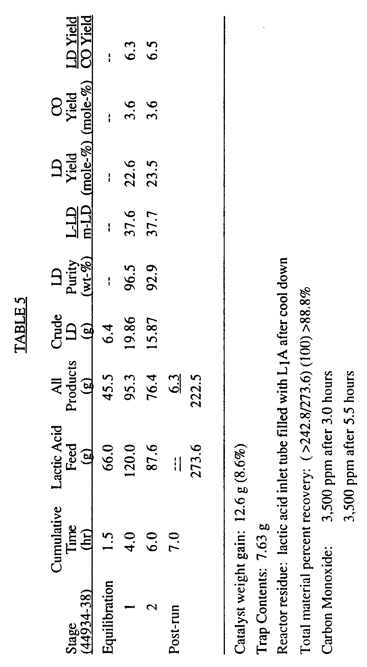
- The initial exotherm of 9°C decreased to 1°C at the end of the run. The observed lactide yields and LD/CO ratios were lower than observed for the silica/alumina catalyst reported above. Accordingly, the next two examples test the effect of the alumina carrier on lactide conversion and its selectivity.
- In this example, 85% lactic acid (36.7 ml/hr) was fed to the reactor having the screen assembly of Example 3 and containing 10-20 mesh gamma alumina/silica gel (93:7, respectively) held at a nominal bed temperature of 205°C. The nitrogen flow rate was 1,596 ml/min, the space time was 3 seconds, weight percent organic in the feed was 25%, and the superficial velocity was about 0.11 ft/sec. The following results were recorded:
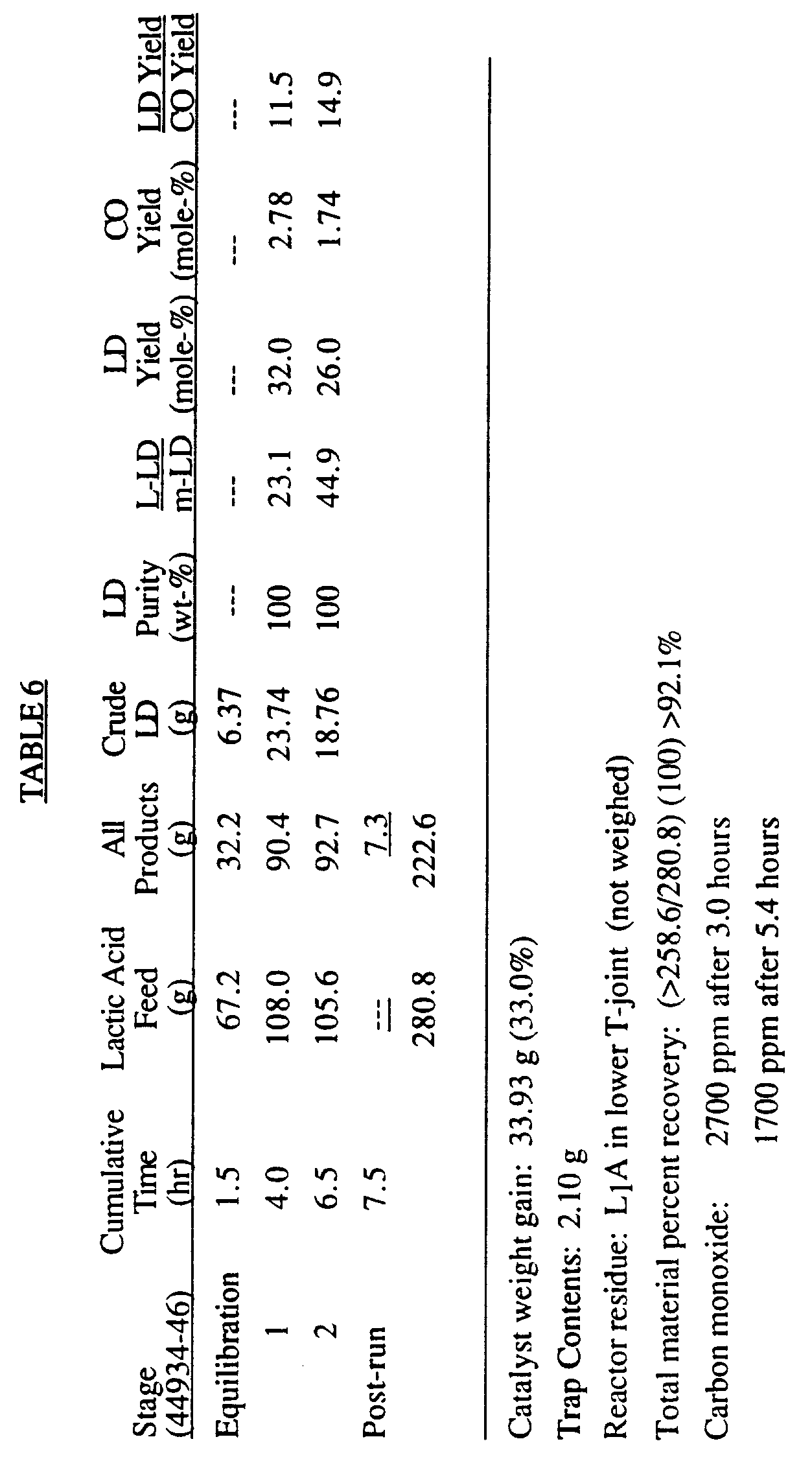
- The initial 15°C exotherm decrease and the reaction was 2°C endothermic at the end run. Even though the LD yield dropped during stage 2, a significant drop in CO resulted in the highest LD/CO ratio observed through this run.
- In this run which utilized a reactor having only a lower 16 mesh screen and an upper 42 mesh screen, 85% lactic acid (35.0 ml/hr) was passed through a reactor containing 10-20 mesh of 99% gamma alumina (Alfa, 90m²/g) held at a nominal bed temperature of 204°C. In this run, the nitrogen flow was 1580 ml/min, the space time was 3.03 seconds, the weight percent organic in the feed was 24.3%, and the superficial velocity again was approximately 0.11 ft/sec. The following results were recorded:

- Stages 2 and 3 filtrates were extracted with methylene chloride within one hour alter formation to yield the following quantities of lactide:

- The initial exotherm of 12°C reduced to 1°C after 2.5 hours and was absent after 5 hours. This catalyst serves to distinguish the relative effect of molybdenum (VI) oxide versus alumina in Example 6. Of importance are the relatively high lactide yields that were obtained and especially the high LD/CO ratios that were one order of magnitude higher than previously observed with any other catalyst. These results and those of Example 7 indicate that small silica quantities significantly decrease the LD/CO ratio when using alumina/silica catalysts. Alumina catalyst alone appears to be superior catalyst compared to alumina/silica mixtures.
- The filtrates from stages 2 and 3 were extracted with methylene chloride soon after the lactide washing procedures were completed to recover the lactide remaining in solution. These residual lactide samples were found to have lower L-LD/meso-LD ratios compared to stages 1 and 2 lactide due to the preferential solubilization of meso-lactide in cold water. The total lactide yields (obtained from initial washing/filtration followed by filtrate extraction) from both stages is the same (34.1%) and the overall L-LD/meso-LD ratios are the same (95.5:4.5 for stage 1 plus extract and 95.6/4.4 for stage 2 plus extract). If the assumption is made that racemization occurs only in LD and most LD was extracted before it could hydrolyze to L₂A , these ratios represent the ultimate L-LD/meso-LD ratio expected after multiple cycles. Interestingly, this ratio appears to approach the 95/5 ratio achieved during the recycle study reported in Example 4.
- These results indicate that molybdenum (VI) oxide used in Example 6 may catalyze carbon monoxide formation, or the alumina substrate used for molybdenum (VI) oxide in Example 6 was prepared differently than the gamma alumina used in this example.
- In this example, using the reactor configuration of Example 8, 85% lactic acid (35.3 ml/hr) was passed through the reactor containing 3 run borosilicate glass beads (washed with water and acetone) held at a nominal bed temperature of 203°C. During this run, the nitrogen flow rate was 1,580 ml/min, the space time was 1.15 seconds within the void volume in the glass beads, the weight percent organics in the feed was 20.44%, and the superficial velocity was approximately 0.11 ft/sec. The following results were recorded:

- The approximately 2°C endotherm was present during the entire run. Some beads had a tacky coating indicating that lactic acid oligomerization was occurring on the glass surfaces.
- The use of glass beads without any catalyst resulted in lower LD yields, though much higher L-LD:meso-LD ratios and LD/CO ratios compared to other catalysts tested.
- In this example using the reactor screen configuration of Example 3, 85% lactic acid (35.1 ml/hr) was passed through an empty reactor maintained at a temperature of about 201°C. During this run, the nitrogen flow was 1,540 ml/sec; the space time was 10.4 seconds; the weight percent organic in feed was 24.8%; and the superficial velocity was about 0.11 ft/sec. No equilibration period was used in this experiment. The following results were recorded.

- There was no exotherm evident during this run. Lactide yields are approximately the same as reported for the glass bead run of Example 9, but the LD/CO ratio has substantially increased. The low lactide purity of 74.7% resulted due to using a lower than normal proportion of cold wash water due to the relatively small amount of lactide obtained.
- Importantly, however, is the conversion of aqueous feed lactic acid into LD using no catalyst or solid packing material in the reactor providing that the LD feed is maintained in the vapor phase at elevated temperature. While LD yields are low, selectivity for LD formation over by-product formation (as measured by the very high LD:CO ratio) and lack of LD racemization (as measured by the high L-LD:meso-LD ratio) appears to be maximized. The effect of alumina catalyst, then, is to improve LD yields, though at the expense of also increasing CO byproduct formation and LD racemization. Silica gel and other catalysts likely also improve LD yields, though they increase CO by-product formation to a greater extent. Nevertheless, depending upon the needs of the operator, LD yield maximization or LD selective conversion maximization and control of LD racemization can be obtained by judicious selection of the presence and type of catalyst (and of course temperature).
- This run replicates the empty reactor run in Example 10, except using the reactor screen configuration of Example 8. In this run, 85% lactic acid (34.0 ml/hr) was fed to the empty reactor maintained at about 204°C. The nitrogen flow rate was 1,580 ml/sec; the space time was 10.2 seconds; the weight percent organic in feed was 23.7%; and the superficial velocity was approximately 0.11 ft/sec.
- The following results were recorded.

- Again, no exotherm was observed. These results again show very high LD/CO and L-LD:meso-LD ratios as in Example 10, but also show increasing lactide yield with time. Extraction of the filtrate obtained from stage 2 yielded an additional 2.47 g solid which analyzed as 90.5 wt-% LD. This extra increment of LD increases the total LD yield to 15.5% for this stage. This result implies that approximately half of the LD typically generated in runs with catalyst beds could have already formed before contacting the catalyst bed. The precursor of the LD is presumed to be mainly L₂A in the aqueous lactic acid feed which cyclizes and readily vaporizes (or vaporizes/cyclizes) under the reaction conditions. The extra lactide produced when catalysts are employed is presumed to originate from vaporized L₁A which is converted in the chemisorbed state to chemisorbed L₂A which is converted into LD on the catalyst surface. Due to the high vapor pressure of LD compared to that of L₂A, the LD formed on the catalyst surface is rapidly and selectively removed by the heated carrier gas.
- The very high L-LD/meso-LD ratios are approximate values since the meso-LD concentration fell below the concentration range used for calibration purposes. However, these L-LD/meso-LD ratios indicate that little or no racemization occurred in this run since the low meso percentages are in the range predicted from the reaction of the approximately 0.3 percent D-L₁A which is present in commercial 85% L-L₁A. The L-LD/meso-LD ratio of extracted stage 2 was found to be approximately 285:1 which indicates that the meso concentration is so low that little selective solubilization of meso-lactide occurs.
- These results further indicate that LD can be made without catalyst in high overall yield if L₁A recycle is employed. Furthermore, LD can be made without catalyst with almost complete retention of configuration of the aqueous lactic acid from which it is derived.
Claims (10)
- A method for making lactide from aqueous lactic acid feed which comprises the steps of:(a) converting aqueous lactic acid feed to its vapor phase by vaporization in a heated gas stream;(b) passing said feed vapors through a vapor phase reaction zone maintained at elevated temperature; and(c) withdrawing from said reaction zone lactide, water, and unreacted aqueous lactic acid feed.
- The method of claim 1 wherein said elevated temperature is in the range from about 150° to 225°C.
- The method of claim 1 or 2 wherein said feed vapors are passed through said vapor phase reaction zone with the aid of a carrier gas.
- The method of claim 3 wherein said carrier gas comprises nitrogen.
- The method of any preceding claim wherein said vapor phase reaction zone contains one or more of an alumina catalyst, silica, or a zeolite.
- The method of any preceding claim further comprising the step of: step (d) passing said withdrawn lactide, water, and unreacted aqueous lactic acid feed through a cold cyclone for separation.
- The method of any preceding claim wherein any oligomeric lactic acid in said feed is converted to one or more of L₁A, L₂A, or L₃A with water for its conversion to its vapor phase.
- The method of any preceding claim wherein said lactic acid feed is monomeric lactic acid (L₁A).
- A cyclic process for making lactide from aqueous lactic acid feed which comprises the steps of:(a) passing make-up aqueous lactic acid feed into a vaporization zone along with unreacted aqueous lactic acid filtrate from another step of the process and therein forming aqueous lactic acid feed vapors by vaporization in a heated gas stream;(b) passing said vapors through a vapor phase reaction zone held at elevated temperature for forming lactide therein;(c) separating lactide from unreacted aqueous lactic acid filtrate; and(d) passing said filtrate into said vaporization zone in step (a) of the process.
- The cyclic process of claim 9 wherein said filtrate is subjected to distillation to concentrate the lactic acid content thereof prior to being passed into said vaporization zone.
Applications Claiming Priority (3)
| Application Number | Priority Date | Filing Date | Title |
|---|---|---|---|
| US07/584,466 US5332839A (en) | 1990-09-18 | 1990-09-18 | Catalytic production of lactide directly from lactic acid |
| US584466 | 1990-09-18 | ||
| PCT/US1991/006775 WO1992005168A1 (en) | 1990-09-18 | 1991-09-18 | Catalytic production of lactide directly from lactic acid |
Publications (2)
| Publication Number | Publication Date |
|---|---|
| EP0549698A1 EP0549698A1 (en) | 1993-07-07 |
| EP0549698B1 true EP0549698B1 (en) | 1994-11-09 |
Family
ID=24337436
Family Applications (1)
| Application Number | Title | Priority Date | Filing Date |
|---|---|---|---|
| EP91917419A Expired - Lifetime EP0549698B1 (en) | 1990-09-18 | 1991-09-18 | Catalytic production of lactide directly from lactic acid |
Country Status (22)
| Country | Link |
|---|---|
| US (1) | US5332839A (en) |
| EP (1) | EP0549698B1 (en) |
| JP (1) | JP3236289B2 (en) |
| KR (1) | KR0171431B1 (en) |
| CN (1) | CN1061223A (en) |
| AT (1) | ATE113944T1 (en) |
| AU (1) | AU652963B2 (en) |
| BR (1) | BR9106854A (en) |
| CA (1) | CA2091689A1 (en) |
| DE (1) | DE69105144T2 (en) |
| DK (1) | DK0549698T3 (en) |
| ES (1) | ES2063527T3 (en) |
| FI (1) | FI95696C (en) |
| HK (1) | HK175695A (en) |
| IE (1) | IE63141B1 (en) |
| IL (1) | IL99520A0 (en) |
| MX (1) | MX9101130A (en) |
| MY (1) | MY106760A (en) |
| NZ (1) | NZ239825A (en) |
| PT (1) | PT98999A (en) |
| WO (1) | WO1992005168A1 (en) |
| ZA (1) | ZA917452B (en) |
Families Citing this family (34)
| Publication number | Priority date | Publication date | Assignee | Title |
|---|---|---|---|---|
| US5274127A (en) * | 1990-09-18 | 1993-12-28 | Biopak Technology, Ltd. | Lactide production from dehydration of aqueous lactic acid feed |
| US5767222A (en) * | 1988-08-08 | 1998-06-16 | Chronopol, Inc. | Degradable polydioxaneone-based materials |
| US5319107A (en) * | 1990-09-18 | 1994-06-07 | Biopak Technology, Ltd. | Method to produce cyclic esters |
| US5326887A (en) * | 1991-02-27 | 1994-07-05 | E. I. Du Pont De Nemours And Company | Process for the preparation of 1,4-dioxane-2,5-diones |
| US6005067A (en) * | 1992-01-24 | 1999-12-21 | Cargill Incorporated | Continuous process for manufacture of lactide polymers with controlled optical purity |
| US5142023A (en) * | 1992-01-24 | 1992-08-25 | Cargill, Incorporated | Continuous process for manufacture of lactide polymers with controlled optical purity |
| US5258488A (en) * | 1992-01-24 | 1993-11-02 | Cargill, Incorporated | Continuous process for manufacture of lactide polymers with controlled optical purity |
| US5247059A (en) * | 1992-01-24 | 1993-09-21 | Cargill, Incorporated | Continuous process for the manufacture of a purified lactide from esters of lactic acid |
| US6326458B1 (en) | 1992-01-24 | 2001-12-04 | Cargill, Inc. | Continuous process for the manufacture of lactide and lactide polymers |
| US5247058A (en) * | 1992-01-24 | 1993-09-21 | Cargill, Incorporated | Continuous process for manufacture of lactide polymers with controlled optical purity |
| US6005068A (en) | 1992-10-02 | 1999-12-21 | Cargill Incorporated | Melt-stable amorphous lactide polymer film and process for manufacture thereof |
| WO1994008090A1 (en) * | 1992-10-02 | 1994-04-14 | Cargill, Incorporated | Paper having a melt-stable lactide polymer coating and process for manufacture thereof |
| US5338822A (en) * | 1992-10-02 | 1994-08-16 | Cargill, Incorporated | Melt-stable lactide polymer composition and process for manufacture thereof |
| EP0615555B1 (en) | 1992-10-02 | 2001-03-21 | Cargill, Incorporated | A melt-stable lactide polymer fabric and process for manufacture thereof |
| FR2726559B1 (en) * | 1994-11-04 | 1997-01-31 | Flamel Tech Sa | PROCESS FOR THE PRODUCTION OF CYCLIC ESTERS OF ALPHA-HYDROXYCARBOXYLIC ACIDS |
| US5801255A (en) * | 1996-08-01 | 1998-09-01 | Shimadzu Corporation | Method for producing lactide and apparatus used therefor |
| US6313319B1 (en) | 1998-09-25 | 2001-11-06 | Shimadzu Corporation | Method for purifying lactide and lactide for food additives |
| IL132289A (en) * | 1999-10-08 | 2003-12-10 | Staley Mfg Co A E | Process for conversion of an extracted carboxylic acid to a non-ionized product |
| WO2001042333A2 (en) | 1999-12-13 | 2001-06-14 | Michigan State University | Process for the preparation of polymers of dimeric cyclic esters |
| JP4565208B2 (en) * | 2000-03-31 | 2010-10-20 | 株式会社クレハ | Method for purifying glycolide |
| DE102007045701B3 (en) * | 2007-09-24 | 2009-05-14 | Uhde Gmbh | Production of lactic acid by fermentation and extraction with amines |
| KR101154029B1 (en) * | 2009-05-20 | 2012-06-07 | 한국화학연구원 | Catalyst for direct conversion of esters of lactic acid to lactide and the method for producing the lactide using the same |
| CN103314098A (en) | 2010-10-28 | 2013-09-18 | 道达尔炼油与销售部 | Use of monascus in organic acid production |
| WO2013160485A1 (en) | 2012-04-28 | 2013-10-31 | Uhde Inventa-Fischer Gmbh | Process for continuous preparation of lactide directly from concentrated lactic acid |
| KR101467202B1 (en) * | 2013-06-21 | 2014-12-01 | 한국화학연구원 | Shaped Catalyst For Direct Preparation of Lactide from Lactic Acid and Preparation of the Shaped Catalyst |
| KR101704563B1 (en) | 2015-10-12 | 2017-02-08 | 한국화학연구원 | Method and apparatus for preparation of lactide using lactide purification process |
| JP2019519609A (en) * | 2016-06-20 | 2019-07-11 | トタル リサーチ アンド テクノロジー フエリユイ | Process for producing lactide in a single step, recovering the hydrolysis of oligomers and catalyst and carrying out with water |
| US10851078B2 (en) * | 2016-06-20 | 2020-12-01 | Total Research & Technology Feluy | Single step lactide production process with heat recovery |
| CN109563068A (en) * | 2016-06-20 | 2019-04-02 | 道达尔研究技术弗吕公司 | By the single stage lactide production technique for decanting recycle-water |
| KR102013714B1 (en) * | 2017-03-09 | 2019-08-23 | 연세대학교 산학협력단 | Continuous lactide synthesis process and apparatus |
| CN111039918A (en) * | 2019-12-24 | 2020-04-21 | 安徽丰原发酵技术工程研究有限公司 | Method for preparing D-lactide by one-step gas phase reaction |
| UA145097U (en) | 2020-05-07 | 2020-11-25 | Товариство З Обмеженою Відповідальністю "Виробнича Група "Техінсервіс" | METHOD OF OBTAINING LACTID FROM C <sub> 3 </sub> -POLIOLS |
| CN114805285A (en) * | 2022-06-07 | 2022-07-29 | 南昌大学 | Method for preparing lactide from L-lactic acid |
| CN115504958B (en) * | 2022-10-20 | 2023-12-19 | 山东寿光巨能金玉米开发有限公司 | Method for joint production of lactide and lactate |
Family Cites Families (44)
| Publication number | Priority date | Publication date | Assignee | Title |
|---|---|---|---|---|
| DE221786C (en) * | ||||
| CA863673A (en) * | 1971-02-16 | K. Schneider Allan | Absorbable suture | |
| DE267826C (en) * | 1912-12-28 | 1913-12-02 | Chemische Werke | Process for the preparation of lactide |
| US1095205A (en) * | 1913-05-15 | 1914-05-05 | Chemische Werke Vorm Dr Heinrich Byk | Manufacture of lactid. |
| US1594843A (en) * | 1921-08-19 | 1926-08-03 | Du Pont | Purification of lactic acid |
| US1995970A (en) * | 1931-04-04 | 1935-03-26 | Du Pont | Polymeric lactide resin |
| US2163268A (en) * | 1933-12-12 | 1939-06-20 | Du Pont | Method for making cyclic esters |
| US2174491A (en) * | 1938-06-28 | 1939-09-26 | Paul D Watson | Method of making lactic acid resinous products |
| US2189572A (en) * | 1938-09-01 | 1940-02-06 | Paul D Watson | Process for fractionating resinous products |
| US2703316A (en) * | 1951-06-05 | 1955-03-01 | Du Pont | Polymers of high melting lactide |
| US2668162A (en) * | 1952-03-20 | 1954-02-02 | Du Pont | Preparation of high molecular weight polyhydroxyacetic ester |
| US2758987A (en) * | 1952-06-05 | 1956-08-14 | Du Pont | Optically active homopolymers containing but one antipodal species of an alpha-monohydroxy monocarboxylic acid |
| US2768973A (en) * | 1954-11-30 | 1956-10-30 | Du Pont | Preparation of glycolaldehyde by hydrolysis of 4-chloro-2-oxodioxolane |
| US3322791A (en) * | 1963-09-26 | 1967-05-30 | Ethicon Inc | Preparation of optically active lactides |
| DE1194142B (en) * | 1963-11-19 | 1965-06-03 | Bayer Ag | Process for UV stabilization of polycarbonates |
| BE674355A (en) * | 1964-12-28 | 1966-06-27 | ||
| DD53074A1 (en) * | 1965-12-18 | 1967-01-05 | Process for the preparation of cyclic ester anhydrides of alpha-hydroxycarboxylic acids | |
| US3457280A (en) * | 1967-06-12 | 1969-07-22 | American Cyanamid Co | Alpha-glycolide and methods for the isolation thereof |
| US3435008A (en) * | 1967-08-22 | 1969-03-25 | American Cyanamid Co | Method for preparation of isomerically pure beta-glycolide and polymerization method for glycolide compositions employing partial hydrolyzate of said beta-glycolide |
| US3597450A (en) * | 1969-11-05 | 1971-08-03 | American Cyanamid Co | Preparation of glycolide polymerizable into polyglycolic acid of consistently high molecular weight |
| US3867190A (en) * | 1971-10-18 | 1975-02-18 | American Cyanamid Co | Reducing capillarity of polyglycolic acid sutures |
| US3736646A (en) * | 1971-10-18 | 1973-06-05 | American Cyanamid Co | Method of attaching surgical needles to multifilament polyglycolic acid absorbable sutures |
| US3960152A (en) * | 1974-01-21 | 1976-06-01 | American Cyanamid Company | Surgical sutures of unsymmetrically substituted 1,4-dioxane-2,5-diones |
| US4033938A (en) * | 1974-01-21 | 1977-07-05 | American Cyanamid Company | Polymers of unsymmetrically substituted 1,4-dioxane-2,5-diones |
| US4070375A (en) * | 1976-08-05 | 1978-01-24 | Chevron Research Company | Process for preparing 1,4-dioxan-2-ones |
| US4727163A (en) * | 1985-07-11 | 1988-02-23 | E. I. Du Pont De Nemours And Company | Process for preparing highly pure cyclic esters |
| DE3708915C2 (en) * | 1987-03-19 | 1996-04-04 | Boehringer Ingelheim Kg | Process for the preparation of lactide |
| EP0261572A1 (en) * | 1986-09-20 | 1988-03-30 | Boehringer Ingelheim Kg | Process for the production of lactide |
| DE3632103A1 (en) * | 1986-09-20 | 1988-03-24 | Boehringer Ingelheim Kg | Process for the preparation of lactide |
| DE3778111D1 (en) * | 1986-10-24 | 1992-05-14 | Boehringer Ingelheim Kg | METHOD FOR PRODUCING AND CLEANING THERMOLABILE COMPOUNDS. |
| EP0275581B1 (en) * | 1986-12-19 | 1992-08-12 | Akzo N.V. | Preparation of polylactic acid and copolymers thereof |
| US4835293A (en) * | 1987-02-24 | 1989-05-30 | E. I. Du Pont De Nemours And Company | Atmospheric pressure process for preparing pure cyclic esters |
| NL8702563A (en) * | 1987-10-28 | 1989-05-16 | Cca Biochem B V | POLYMER LACTIDE, METHOD FOR PREPARING SUCH A POLYMER LACTIDE, AND A COMPOSITION CONTAINING SUCH POLYMER LACTIDE. |
| EP0339882A1 (en) * | 1988-04-27 | 1989-11-02 | MITSUI TOATSU CHEMICALS, Inc. | Process for the production of lactide |
| US5274127A (en) * | 1990-09-18 | 1993-12-28 | Biopak Technology, Ltd. | Lactide production from dehydration of aqueous lactic acid feed |
| US5068418A (en) * | 1989-05-08 | 1991-11-26 | Uop | Separation of lactic acid from fermentation broth with an anionic polymeric absorbent |
| US5075115A (en) * | 1990-04-02 | 1991-12-24 | Fmc Corporation | Process for polymerizing poly(lactic acid) |
| US5023349A (en) * | 1990-05-08 | 1991-06-11 | E. I. Du Pont De Nemours And Company | Continuous process for rapid conversion of oligomers to cyclic esters |
| JPH05506242A (en) * | 1990-05-03 | 1993-09-16 | イー・アイ・デユポン・ドウ・ヌムール・アンド・カンパニー | Improved method for rapid production of cyclic esters |
| US5091544A (en) * | 1990-05-08 | 1992-02-25 | E. I. Du Pont De Nemours And Company | Process for rapid conversion of oligomers to cyclic esters |
| US5043458A (en) * | 1990-05-03 | 1991-08-27 | E. I. Du Pont De Nemours And Company | One-step continuous process for preparing cyclic esters |
| US5023350A (en) * | 1990-05-24 | 1991-06-11 | E. I. Du Pont De Nemours And Company | Process for the purification of cyclic esters |
| US5138074A (en) * | 1990-06-28 | 1992-08-11 | E. I. Du Pont De Nemours And Company | Continuous catalyzed vapor phase dimeric cyclic ester process |
| US5089632A (en) * | 1991-01-30 | 1992-02-18 | E. I. Du Pont De Nemours And Company | Process for preparing cyclic esters using a fluorocarbon |
-
1990
- 1990-09-18 US US07/584,466 patent/US5332839A/en not_active Expired - Fee Related
-
1991
- 1991-09-17 NZ NZ239825A patent/NZ239825A/en unknown
- 1991-09-17 IE IE327391A patent/IE63141B1/en not_active IP Right Cessation
- 1991-09-18 AT AT91917419T patent/ATE113944T1/en not_active IP Right Cessation
- 1991-09-18 CN CN91108486A patent/CN1061223A/en active Pending
- 1991-09-18 ES ES91917419T patent/ES2063527T3/en not_active Expired - Lifetime
- 1991-09-18 PT PT98999A patent/PT98999A/en not_active Application Discontinuation
- 1991-09-18 WO PCT/US1991/006775 patent/WO1992005168A1/en not_active Ceased
- 1991-09-18 ZA ZA917452A patent/ZA917452B/en unknown
- 1991-09-18 CA CA002091689A patent/CA2091689A1/en not_active Abandoned
- 1991-09-18 BR BR919106854A patent/BR9106854A/en not_active Application Discontinuation
- 1991-09-18 AU AU86305/91A patent/AU652963B2/en not_active Ceased
- 1991-09-18 DK DK91917419.3T patent/DK0549698T3/en active
- 1991-09-18 MY MYPI91001694A patent/MY106760A/en unknown
- 1991-09-18 DE DE69105144T patent/DE69105144T2/en not_active Expired - Fee Related
- 1991-09-18 MX MX9101130A patent/MX9101130A/en not_active IP Right Cessation
- 1991-09-18 JP JP51606391A patent/JP3236289B2/en not_active Expired - Fee Related
- 1991-09-18 EP EP91917419A patent/EP0549698B1/en not_active Expired - Lifetime
- 1991-09-19 IL IL99520A patent/IL99520A0/en unknown
-
1993
- 1993-03-17 KR KR1019930700791A patent/KR0171431B1/en not_active Expired - Fee Related
- 1993-03-17 FI FI931184A patent/FI95696C/en not_active IP Right Cessation
-
1995
- 1995-11-16 HK HK175695A patent/HK175695A/en not_active IP Right Cessation
Also Published As
| Publication number | Publication date |
|---|---|
| ZA917452B (en) | 1992-05-27 |
| US5332839A (en) | 1994-07-26 |
| BR9106854A (en) | 1993-08-24 |
| MY106760A (en) | 1995-07-31 |
| JP3236289B2 (en) | 2001-12-10 |
| EP0549698A1 (en) | 1993-07-07 |
| KR0171431B1 (en) | 1999-02-01 |
| PT98999A (en) | 1992-07-31 |
| KR930702330A (en) | 1993-09-08 |
| FI95696B (en) | 1995-11-30 |
| JPH06501467A (en) | 1994-02-17 |
| CA2091689A1 (en) | 1992-03-19 |
| AU8630591A (en) | 1992-04-15 |
| CN1061223A (en) | 1992-05-20 |
| IL99520A0 (en) | 1992-08-18 |
| DK0549698T3 (en) | 1995-03-27 |
| DE69105144T2 (en) | 1995-03-23 |
| FI931184A0 (en) | 1993-03-17 |
| ATE113944T1 (en) | 1994-11-15 |
| HK175695A (en) | 1995-11-24 |
| MX9101130A (en) | 1992-05-04 |
| DE69105144D1 (en) | 1994-12-15 |
| NZ239825A (en) | 1993-08-26 |
| IE913273A1 (en) | 1992-02-25 |
| FI931184L (en) | 1993-03-17 |
| WO1992005168A1 (en) | 1992-04-02 |
| ES2063527T3 (en) | 1995-01-01 |
| IE63141B1 (en) | 1995-03-22 |
| FI95696C (en) | 1996-03-11 |
| AU652963B2 (en) | 1994-09-15 |
Similar Documents
| Publication | Publication Date | Title |
|---|---|---|
| AU652963B2 (en) | Catalytic production of lactide directly from lactic acid | |
| US5319107A (en) | Method to produce cyclic esters | |
| EP0552226B1 (en) | Lactide production from dehydration of aqueous lactic acid feed | |
| EP2222658B1 (en) | Method for obtaining lactide | |
| JPH07505150A (en) | Solvent-free cyclic ester dimer distillation method | |
| JPH05507076A (en) | Cyclic ester purification method | |
| KR101459819B1 (en) | A method for lactide synthesis from lactic acid salt | |
| KR101396007B1 (en) | Process for preparing tetramethyl glycolide | |
| US5196551A (en) | Co-vaporization process for preparing lactide | |
| US5288881A (en) | Continuous reduced pressure dimeric cyclic ester production | |
| US2072101A (en) | Manufacture of organic compounds | |
| JP2005187425A (en) | Method for producing spiroglycol | |
| US8598385B2 (en) | Process for the preparation of N-vinylcarboxamides | |
| EP0758311A1 (en) | Catalyst recovery in the carbonylation of chlorobutenes to pentenoyl chloride | |
| JPH1036366A (en) | Lactide production method |
Legal Events
| Date | Code | Title | Description |
|---|---|---|---|
| PUAI | Public reference made under article 153(3) epc to a published international application that has entered the european phase |
Free format text: ORIGINAL CODE: 0009012 |
|
| 17P | Request for examination filed |
Effective date: 19930403 |
|
| AK | Designated contracting states |
Kind code of ref document: A1 Designated state(s): AT BE CH DE DK ES FR GB GR IT LI LU NL SE |
|
| 17Q | First examination report despatched |
Effective date: 19931223 |
|
| GRAA | (expected) grant |
Free format text: ORIGINAL CODE: 0009210 |
|
| AK | Designated contracting states |
Kind code of ref document: B1 Designated state(s): AT BE CH DE DK ES FR GB GR IT LI LU NL SE |
|
| PG25 | Lapsed in a contracting state [announced via postgrant information from national office to epo] |
Ref country code: LI Effective date: 19941109 Ref country code: GR Free format text: LAPSE BECAUSE OF FAILURE TO SUBMIT A TRANSLATION OF THE DESCRIPTION OR TO PAY THE FEE WITHIN THE PRESCRIBED TIME-LIMIT Effective date: 19941109 Ref country code: CH Effective date: 19941109 |
|
| REF | Corresponds to: |
Ref document number: 113944 Country of ref document: AT Date of ref document: 19941115 Kind code of ref document: T |
|
| ITF | It: translation for a ep patent filed | ||
| REF | Corresponds to: |
Ref document number: 69105144 Country of ref document: DE Date of ref document: 19941215 |
|
| REG | Reference to a national code |
Ref country code: ES Ref legal event code: FG2A Ref document number: 2063527 Country of ref document: ES Kind code of ref document: T3 |
|
| EAL | Se: european patent in force in sweden |
Ref document number: 91917419.3 |
|
| REG | Reference to a national code |
Ref country code: CH Ref legal event code: PL |
|
| ET | Fr: translation filed | ||
| REG | Reference to a national code |
Ref country code: DK Ref legal event code: T3 |
|
| PLBE | No opposition filed within time limit |
Free format text: ORIGINAL CODE: 0009261 |
|
| STAA | Information on the status of an ep patent application or granted ep patent |
Free format text: STATUS: NO OPPOSITION FILED WITHIN TIME LIMIT |
|
| PG25 | Lapsed in a contracting state [announced via postgrant information from national office to epo] |
Ref country code: LU Free format text: LAPSE BECAUSE OF NON-PAYMENT OF DUE FEES Effective date: 19950930 |
|
| 26N | No opposition filed | ||
| PGFP | Annual fee paid to national office [announced via postgrant information from national office to epo] |
Ref country code: DK Payment date: 19960909 Year of fee payment: 6 |
|
| PGFP | Annual fee paid to national office [announced via postgrant information from national office to epo] |
Ref country code: AT Payment date: 19960912 Year of fee payment: 6 |
|
| PGFP | Annual fee paid to national office [announced via postgrant information from national office to epo] |
Ref country code: BE Payment date: 19961118 Year of fee payment: 6 |
|
| PG25 | Lapsed in a contracting state [announced via postgrant information from national office to epo] |
Ref country code: DK Free format text: LAPSE BECAUSE OF NON-PAYMENT OF DUE FEES Effective date: 19970918 Ref country code: AT Free format text: LAPSE BECAUSE OF NON-PAYMENT OF DUE FEES Effective date: 19970918 |
|
| PGFP | Annual fee paid to national office [announced via postgrant information from national office to epo] |
Ref country code: SE Payment date: 19970918 Year of fee payment: 7 |
|
| REG | Reference to a national code |
Ref country code: DK Ref legal event code: EBP |
|
| PG25 | Lapsed in a contracting state [announced via postgrant information from national office to epo] |
Ref country code: BE Free format text: LAPSE BECAUSE OF NON-PAYMENT OF DUE FEES Effective date: 19970930 |
|
| BERE | Be: lapsed |
Owner name: BIOPAK TECHNOLOGY LTD Effective date: 19970930 |
|
| PG25 | Lapsed in a contracting state [announced via postgrant information from national office to epo] |
Ref country code: SE Free format text: LAPSE BECAUSE OF NON-PAYMENT OF DUE FEES Effective date: 19980919 |
|
| EUG | Se: european patent has lapsed |
Ref document number: 91917419.3 |
|
| REG | Reference to a national code |
Ref country code: GB Ref legal event code: IF02 |
|
| PGFP | Annual fee paid to national office [announced via postgrant information from national office to epo] |
Ref country code: NL Payment date: 20030909 Year of fee payment: 13 |
|
| PGFP | Annual fee paid to national office [announced via postgrant information from national office to epo] |
Ref country code: GB Payment date: 20030910 Year of fee payment: 13 |
|
| PGFP | Annual fee paid to national office [announced via postgrant information from national office to epo] |
Ref country code: FR Payment date: 20030918 Year of fee payment: 13 |
|
| PGFP | Annual fee paid to national office [announced via postgrant information from national office to epo] |
Ref country code: ES Payment date: 20031008 Year of fee payment: 13 |
|
| PGFP | Annual fee paid to national office [announced via postgrant information from national office to epo] |
Ref country code: DE Payment date: 20031031 Year of fee payment: 13 |
|
| PG25 | Lapsed in a contracting state [announced via postgrant information from national office to epo] |
Ref country code: GB Free format text: LAPSE BECAUSE OF NON-PAYMENT OF DUE FEES Effective date: 20040918 |
|
| PG25 | Lapsed in a contracting state [announced via postgrant information from national office to epo] |
Ref country code: ES Free format text: LAPSE BECAUSE OF NON-PAYMENT OF DUE FEES Effective date: 20040920 |
|
| PG25 | Lapsed in a contracting state [announced via postgrant information from national office to epo] |
Ref country code: NL Free format text: LAPSE BECAUSE OF NON-PAYMENT OF DUE FEES Effective date: 20050401 Ref country code: DE Free format text: LAPSE BECAUSE OF NON-PAYMENT OF DUE FEES Effective date: 20050401 |
|
| GBPC | Gb: european patent ceased through non-payment of renewal fee |
Effective date: 20040918 |
|
| PG25 | Lapsed in a contracting state [announced via postgrant information from national office to epo] |
Ref country code: FR Free format text: LAPSE BECAUSE OF NON-PAYMENT OF DUE FEES Effective date: 20050531 |
|
| NLV4 | Nl: lapsed or anulled due to non-payment of the annual fee |
Effective date: 20050401 |
|
| REG | Reference to a national code |
Ref country code: FR Ref legal event code: ST |
|
| PG25 | Lapsed in a contracting state [announced via postgrant information from national office to epo] |
Ref country code: IT Free format text: LAPSE BECAUSE OF NON-PAYMENT OF DUE FEES;WARNING: LAPSES OF ITALIAN PATENTS WITH EFFECTIVE DATE BEFORE 2007 MAY HAVE OCCURRED AT ANY TIME BEFORE 2007. THE CORRECT EFFECTIVE DATE MAY BE DIFFERENT FROM THE ONE RECORDED. Effective date: 20050918 |
|
| REG | Reference to a national code |
Ref country code: ES Ref legal event code: FD2A Effective date: 20040920 |