EP0548915B1 - Control circuit for predominantly inductive loads, in particular, electroinjectors - Google Patents
Control circuit for predominantly inductive loads, in particular, electroinjectors Download PDFInfo
- Publication number
- EP0548915B1 EP0548915B1 EP92121798A EP92121798A EP0548915B1 EP 0548915 B1 EP0548915 B1 EP 0548915B1 EP 92121798 A EP92121798 A EP 92121798A EP 92121798 A EP92121798 A EP 92121798A EP 0548915 B1 EP0548915 B1 EP 0548915B1
- Authority
- EP
- European Patent Office
- Prior art keywords
- load
- circuit
- swi
- switch
- swr
- Prior art date
- Legal status (The legal status is an assumption and is not a legal conclusion. Google has not performed a legal analysis and makes no representation as to the accuracy of the status listed.)
- Expired - Lifetime
Links
Images


Classifications
-
- H—ELECTRICITY
- H01—ELECTRIC ELEMENTS
- H01F—MAGNETS; INDUCTANCES; TRANSFORMERS; SELECTION OF MATERIALS FOR THEIR MAGNETIC PROPERTIES
- H01F7/00—Magnets
- H01F7/06—Electromagnets; Actuators including electromagnets
- H01F7/08—Electromagnets; Actuators including electromagnets with armatures
- H01F7/18—Circuit arrangements for obtaining desired operating characteristics, e.g. for slow operation, for sequential energisation of windings, for high-speed energisation of windings
- H01F7/1805—Circuit arrangements for holding the operation of electromagnets or for holding the armature in attracted position with reduced energising current
- H01F7/1816—Circuit arrangements for holding the operation of electromagnets or for holding the armature in attracted position with reduced energising current making use of an energy accumulator
-
- F—MECHANICAL ENGINEERING; LIGHTING; HEATING; WEAPONS; BLASTING
- F02—COMBUSTION ENGINES; HOT-GAS OR COMBUSTION-PRODUCT ENGINE PLANTS
- F02D—CONTROLLING COMBUSTION ENGINES
- F02D41/00—Electrical control of supply of combustible mixture or its constituents
- F02D41/20—Output circuits, e.g. for controlling currents in command coils
-
- H—ELECTRICITY
- H01—ELECTRIC ELEMENTS
- H01H—ELECTRIC SWITCHES; RELAYS; SELECTORS; EMERGENCY PROTECTIVE DEVICES
- H01H47/00—Circuit arrangements not adapted to a particular application of the relay and designed to obtain desired operating characteristics or to provide energising current
- H01H47/02—Circuit arrangements not adapted to a particular application of the relay and designed to obtain desired operating characteristics or to provide energising current for modifying the operation of the relay
- H01H47/04—Circuit arrangements not adapted to a particular application of the relay and designed to obtain desired operating characteristics or to provide energising current for modifying the operation of the relay for holding armature in attracted position, e.g. when initial energising circuit is interrupted; for maintaining armature in attracted position, e.g. with reduced energising current
- H01H47/043—Circuit arrangements not adapted to a particular application of the relay and designed to obtain desired operating characteristics or to provide energising current for modifying the operation of the relay for holding armature in attracted position, e.g. when initial energising circuit is interrupted; for maintaining armature in attracted position, e.g. with reduced energising current making use of an energy accumulator
-
- F—MECHANICAL ENGINEERING; LIGHTING; HEATING; WEAPONS; BLASTING
- F02—COMBUSTION ENGINES; HOT-GAS OR COMBUSTION-PRODUCT ENGINE PLANTS
- F02D—CONTROLLING COMBUSTION ENGINES
- F02D41/00—Electrical control of supply of combustible mixture or its constituents
- F02D41/20—Output circuits, e.g. for controlling currents in command coils
- F02D2041/2003—Output circuits, e.g. for controlling currents in command coils using means for creating a boost voltage, i.e. generation or use of a voltage higher than the battery voltage, e.g. to speed up injector opening
- F02D2041/2006—Output circuits, e.g. for controlling currents in command coils using means for creating a boost voltage, i.e. generation or use of a voltage higher than the battery voltage, e.g. to speed up injector opening by using a boost capacitor
-
- F—MECHANICAL ENGINEERING; LIGHTING; HEATING; WEAPONS; BLASTING
- F02—COMBUSTION ENGINES; HOT-GAS OR COMBUSTION-PRODUCT ENGINE PLANTS
- F02D—CONTROLLING COMBUSTION ENGINES
- F02D41/00—Electrical control of supply of combustible mixture or its constituents
- F02D41/20—Output circuits, e.g. for controlling currents in command coils
- F02D2041/202—Output circuits, e.g. for controlling currents in command coils characterised by the control of the circuit
- F02D2041/2024—Output circuits, e.g. for controlling currents in command coils characterised by the control of the circuit the control switching a load after time-on and time-off pulses
- F02D2041/2027—Control of the current by pulse width modulation or duty cycle control
-
- F—MECHANICAL ENGINEERING; LIGHTING; HEATING; WEAPONS; BLASTING
- F02—COMBUSTION ENGINES; HOT-GAS OR COMBUSTION-PRODUCT ENGINE PLANTS
- F02D—CONTROLLING COMBUSTION ENGINES
- F02D41/00—Electrical control of supply of combustible mixture or its constituents
- F02D41/20—Output circuits, e.g. for controlling currents in command coils
- F02D2041/202—Output circuits, e.g. for controlling currents in command coils characterised by the control of the circuit
- F02D2041/2034—Control of the current gradient
-
- H—ELECTRICITY
- H01—ELECTRIC ELEMENTS
- H01F—MAGNETS; INDUCTANCES; TRANSFORMERS; SELECTION OF MATERIALS FOR THEIR MAGNETIC PROPERTIES
- H01F7/00—Magnets
- H01F7/06—Electromagnets; Actuators including electromagnets
- H01F7/08—Electromagnets; Actuators including electromagnets with armatures
- H01F7/18—Circuit arrangements for obtaining desired operating characteristics, e.g. for slow operation, for sequential energisation of windings, for high-speed energisation of windings
- H01F7/1805—Circuit arrangements for holding the operation of electromagnets or for holding the armature in attracted position with reduced energising current
- H01F7/1816—Circuit arrangements for holding the operation of electromagnets or for holding the armature in attracted position with reduced energising current making use of an energy accumulator
- H01F2007/1822—Circuit arrangements for holding the operation of electromagnets or for holding the armature in attracted position with reduced energising current making use of an energy accumulator using a capacitor to produce a boost voltage
Definitions
- the present invention relates to a control circuit for predominantly inductive loads, in particular, electroinjectors forming part of an internal combustion engine supply system, as defined in the preamble of claim 1.
- the supply current to the injectors must present a pattern comprising, in general, a rapidly increasing portion, a portion increasing more slowly, a portion oscillating about a mean value, and a rapidly decreasing portion.
- the circuits currently employed for achieving such a pattern substantially comprise a low-voltage supply source and a reactive circuit consisting of an inductor and capacitor for storing the energy required for producing a rapid current pulse in the load.
- the inductor is charged to a given current and then connected to the capacitor, so as to form a resonant circuit and transfer energy from the inductor to the capacitor, which is thus charged for subsequently supplying the load (injector actuator) with the required current pulse.
- a major drawback of the above known circuit is that, for achieving the high currents required, large-size components such as cup-shaped or toroidal cores are used as inductors on the reactive circuit, thus increasing the size and cost of the overall circuit.
- each actuator presents a so-called “snubber” circuit comprising a capacitor and resistor connected parallel to the actuator, and which provide for absorbing and dissipating the energy of the recirculating current of the actuator.
- capacitors further increase the overall size of the circuit.
- a control circuit of the type defined in the preamble of claim 1 is disclosed in FR-A-2 538 942.
- control circuit for predominantly inductive loads in particular electroinjectors, having the features claimed in claim 1.
- Number 30 in Fig.1 indicates a supply system for an internal combustion engine 32, more specifically, a supercharged diesel engine.
- the continuous lines indicate the fuel conduits, and the dotted lines the electric lines relative to measured quantity signals, controls and supply. More specifically, system 30 comprises:
- Central control unit 12 is connected to control circuit 100 of injectors 7 over a number of supply lines 56, one for each injector 7, for controlling the injection phases; and controls pressure regulator 4 over line 57, both lines 56 and 57 extending from unit 12.
- Unit 12 and control circuit 100 are also connected over line 58 from unit 12, and line 59 from circuit 100, as explained in more detail later on.
- circuit 100 comprises two input terminals 102 and 103 connectable to a supply source B consisting of a low-voltage battery. More specifically, terminal 102 is connected to the anode of a diode D2, the cathode of which is connected to a first common line 104 (actuator line); and terminal 103 is connected directly to a second common line 105 (ground).
- Circuit 100 also comprises a number of actuator circuits 106 parallel connected between lines 104 and 105, and each comprising an actuator Li, a storage capacitor Ci, a coupling diode Di, and a controlled electronic switch SWi. More specifically, each actuator Li, consisting of a coil wound about a core and defining the predominantly inductive load, presents one terminal connected to line 104, and the other terminal, defining node 107, connected to the anode of diode Di for connecting actuator Li to a third common line 112 (capacitance line).
- each actuator Li consisting of a coil wound about a core and defining the predominantly inductive load, presents one terminal connected to line 104, and the other terminal, defining node 107, connected to the anode of diode Di for connecting actuator Li to a third common line 112 (capacitance line).
- each diode Di is connected to a second node 113 in turn connected to capacitance line 112 and to a first terminal of respective capacitor Ci, which provides for storing energy at a higher voltage than battery B, and the other terminal of which is connected to ground line 105.
- Each switch SWi which provides for connecting actuator Li to battery B and for transferring energy from actuator Li to the circuit consisting of the parallel connection of storage capacitors Ci, is located between node 107 and ground 105, and presents a control input 108 connected to unit 12 via control line 56, over which unit 12 supplies a signal s i for selecting the actuator to be enabled, as described in more detail later on.
- Circuit 100 also comprises the series connection of an electronic switch SWR and a diode D1, which provide for connecting capacitance line 112 to actuator line 104 and for recirculating the current in load Li. More specifically, switch SWR presents a first terminal connected to capacitance line 112; a second terminal connected to the anode of diode D1, the cathode of which is connected to actuator line 104; and a control terminal 114 connected to unit 12 via control line 58 over which unit 12 supplies a signal s 1 for controlling switch SWR. Finally, line 112 is connected to unit 12 via line 59 for enabling unit 12 to monitor the voltage on line 112.
- Circuit 100 charges storage capacitors Ci to an appropriate voltage, and supplies actuators Li with current Ii, the pattern of which presents a high-amplitude portion with a rapid leading edge, followed by a lower-amplitude portion terminating with a rapid trailing edge, as described below with reference to Fig.s 3 to 5.
- switches SWR and SWi are open (low logic level of signals s 1 and s i ); and storage capacitors Ci are charged to a given high voltage (voltage V C of value V 1 ), so that the voltage drop between capacitance line 112 and actuator line 104 is such as to reverse-bias diodes Di, and current Ii in the actuators is zero.
- switch SWR is closed, so as to switch actuator line 104 to the voltage level of capacitance line 112.
- unit 12 selects the required actuator Li by switching respective signal s i to high and so closing respective switch SWi, so that the selected actuator Li is connected between capacitance line 112 and ground 105, parallel to capacitors Ci with which it forms a resonant circuit.
- a current pulse is therefore formed consisting of a high-frequency sinusoid portion (the value of which is determined by the inductance of actuator Li and the capacitance of capacitors Ci) and produced by rapid discharge of the energy stored in capacitors Ci, thus resulting in a simultaneous rapid reduction in voltage V C of capacitors Ci.
- switch SWi is again closed, the selected actuator Li is again charged by battery B, and respective diode Di opens to disconnect capacitance line 112.
- current Ii in the actuator again increases with a time constant of L/R, where R is the resistance of the actuator coil, components B, D2 and SWi, and the connecting line, despite the L value differing as compared with phase t 2 -t 3 , due to the different current level.
- switch SWi is opened at instant t 5 , actuator Li is again discharged, so that, by appropriately opening and closing switch SWi, the current in actuator Li may be maintained in such a manner as to oscillate about a predetermined medium-low value.
- switches SWR and SWi are opened successively.
- switch SWR is opened at instant t 6 with switch SWi open.
- diode Di is biased directly, so as to connect actuator Li to capacitance line 112 and again form a resonant circuit; actuator Li therefore discharges rapidly into capacitors Ci; current Ii decreases in the form of a high-frequency sinusoid portion; and the energy previously stored by actuator Li is transferred to capacitors Ci, the voltage of which thus increases rapidly.
- unit 12 again closes one or more of switches SWi, so as to again close the circuit including battery B and the actuator Li relative to each closed switch SWi, so that each actuator Li is supplied with current increasing with a time constant of L/R.
- capacitors Ci remain isolated.
- switch SWi (or all the switches closed previously) is again opened, so that, as in interval t 6 -t 7 , energy is transferred from the actuator to capacitors Ci, current Ii in actuator Li is zeroed (instant t 10 ), and the voltage in capacitance line 112 increases.
- the Fig.2 circuit also provides for a second operating mode, as shown in Fig.4.
- capacitors Ci are initially charged to level V 1 ; switches SWR and SWi are open; actuator line 104 is switched to level V 1 when switch SWR is closed (instant t 0 ); closure of a given switch SWi (instant t 1 ) provides for selecting a given actuator Li, generating a current pulse in the actuator, and rapidly charging the actuator at the expense of capacitors Ci, which discharge to approximately the value of battery B (instant t 2 ); and the selected actuator Li is subsequently supplied by battery B, until the relative switch SWi is opened (instant t 3 ).
- switch SWR is opened in the interval t 2 -t 3 in no way affects operation of the circuit as described above.
- actuator Li is prevented from discharging through the circuit including switch SWR, so that energy can only be transferred from actuator Li to capacitors Ci, thus resulting in a first charge of capacitors Ci in interval t 3 -t 4 , as shown in Fig.4.
- switch SWi is closed (instant t 4 )
- actuator Li is again connected to the circuit including battery B, and so begins charging via diode D2, while the relative diode Di is disabled for disconnecting actuator Li from capacitance line 112, which is thus maintained at the previous voltage level.
- switch SWi is again opened, so that the energy stored by actuator Li in the foregoing interval t 4 -t 5 is transferred to capacitors Ci, which are thus charged directly by the selected actuator during the low-current operating phase, using the recirculating current of the actuator itself.
- the current in the actuator is zeroed by keeping the relative switch SWi open subsequent to instant t 7 , as shown in Fig.4.
- the voltage of capacitors Ci may be limited to a predetermined value by appropriately delaying the opening of switch SWR subsequent to instant t 3 , so that the initial opening phases of switches SWi provide for recirculating the actuator current through switch SWR, without charging capacitors Ci, which are only charged after a given number of opening and closing cycles of switches SWi.
- the energy stored in actuators Li instead of being dissipated, as in known circuits, during the recirculating phase, is employed for charging capacitors Ci, which in turn provide for rapidly supplying the selected actuators.
- energy is transferred continually in alternate phases between the actuators and capacitors, thus reducing the number of components and dissipation of the circuit, as well as increasing the rapidity with which the various phases are performed.
- connection of actuator circuits 106 to the same line 104 provides for transferring energy from one circuit 106 to the next according to the injection phases provided for by unit 12.
- the resulting high-speed response of the circuit also provides for achieving a pilot injection phase prior to actual injection.
- Proposals have been made, in fact, for preceding actual injection with a shorter pilot injection phase, for initiating combustion with a limited amount of fuel and so reducing the rate of heat release, noise level, and the formation of nitric oxide.
- the delays introduced by the control circuit components and injectors and the operating frequency involved currently prevent two distinct injection phases from being achieved in rapid succession. In actual practice, in fact, the two phases merge, with one continuous opening operation of the injector ranging from the start of the pilot phase to the end of the actual injection phase.
- the present invention provides for achieving a pilot phase temporally distinct from the actual injection phase.
- Fig.5 showing time graphs of quantities s 1 , s i , V C and Ii.
- signals s 1 and s i are low, capacitors Ci are charged to voltage V C of value V 1 , and the actuators are discharged.
- switch SWR is closed (by switching signal s 1 ) and, at instant t 1 , switch SWi of the selected actuator is closed, thus generating a current pulse Ii in the actuator due to rapid discharge of capacitors Ci.
- the voltage in capacitance line 112 equals that of battery B, which therefore takes over supply of the actuator from capacitors Ci, thus enabling a further, slower, increase in current Ii of actuator Li (pilot injection phase).
- switch SWR is again opened; and, at instant t 4 , switch SWi is also opened, so that the current in actuator Li falls rapidly to zero at instant t 5 , and, at the same time, the voltage in capacitors Ci increases rapidly to value V 3 by virtue of the energy in actuator Li being transferred to capacitors Ci.
- switch SWR is again closed; and, at instant t 7 , switch SWi of the actuator previously selected for the pilot phase is again closed, followed by the actual, longer, injection phase according to either one of the operating modes in Fig.s 3 and 4.
- the actual injection phase is performed as shown in Fig.3 and therefore requires no further description.
- the circuit according to the present invention provides for achieving the required current patterns with no need for auxiliary inductors or capacitors. Moreover, by virtue of the recirculating current of actuators Li being absorbed by and charging capacitors Ci, no "snubbing" capacitors are required, as on known circuits, for protecting switches SWi, thus greatly reducing the size and cost of the circuit according to the present invention.
Landscapes
- Engineering & Computer Science (AREA)
- Physics & Mathematics (AREA)
- Electromagnetism (AREA)
- Power Engineering (AREA)
- Chemical & Material Sciences (AREA)
- Combustion & Propulsion (AREA)
- Mechanical Engineering (AREA)
- General Engineering & Computer Science (AREA)
- Electrical Control Of Air Or Fuel Supplied To Internal-Combustion Engine (AREA)
- Fuel-Injection Apparatus (AREA)
- Relay Circuits (AREA)
- Electronic Switches (AREA)
Description
- The present invention relates to a control circuit for predominantly inductive loads, in particular, electroinjectors forming part of an internal combustion engine supply system, as defined in the preamble of
claim 1. - For controlling internal combustion engine injectors, the supply current to the injectors must present a pattern comprising, in general, a rapidly increasing portion, a portion increasing more slowly, a portion oscillating about a mean value, and a rapidly decreasing portion. The circuits currently employed for achieving such a pattern substantially comprise a low-voltage supply source and a reactive circuit consisting of an inductor and capacitor for storing the energy required for producing a rapid current pulse in the load. For this purpose, the inductor is charged to a given current and then connected to the capacitor, so as to form a resonant circuit and transfer energy from the inductor to the capacitor, which is thus charged for subsequently supplying the load (injector actuator) with the required current pulse.
- A major drawback of the above known circuit is that, for achieving the high currents required, large-size components such as cup-shaped or toroidal cores are used as inductors on the reactive circuit, thus increasing the size and cost of the overall circuit.
- The above problem is further compounded by the fact that, for protecting the control elements of the actuators, each actuator presents a so-called "snubber" circuit comprising a capacitor and resistor connected parallel to the actuator, and which provide for absorbing and dissipating the energy of the recirculating current of the actuator. Such capacitors further increase the overall size of the circuit.
- A control circuit of the type defined in the preamble of
claim 1 is disclosed in FR-A-2 538 942. - It is an object of the present invention to provide a more compact control circuit as compared with known types.
- According to the present invention, there is provided a control circuit for predominantly inductive loads, in particular electroinjectors, having the features claimed in
claim 1. - A preferred, non-limiting embodiment of the present invention will be described by way of example with reference to the accompanying drawings, in which:
- Fig.1 shows a block diagram of a supply system including the control circuit according to the present invention;
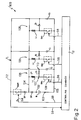
- Fig.2 shows a simplified diagram of the circuit according to the present invention;
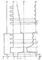
- Fig.3 shows a time graph of a number of quantities in the Fig.2 circuit and relative to a first operating mode of the circuit;
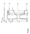
- Fig.4 shows a time graph of the Fig.3 quantities relative to a second operating mode of the circuit;
- Fig.5 shows a time graph of the Fig.2-3 quantities relative to a third operating mode of the circuit.
-
Number 30 in Fig.1 indicates a supply system for aninternal combustion engine 32, more specifically, a supercharged diesel engine. In Fig.1, the continuous lines indicate the fuel conduits, and the dotted lines the electric lines relative to measured quantity signals, controls and supply. More specifically,system 30 comprises: - an
electric supply pump 1 for ensuring a given head (1-3 bar) infuel supply conduit 31; - a
fuel filter 2 onconduit 31, downstream frompump 1; - a high-
pressure pump 3 downstream fromfilter 2, for generating a high injection pressure as required (up to 1500 bar); - a high-
pressure supply line 5 frompump 3; - a pressure regulator 4 on high-
pressure supply line 5 and consisting of an electronically controlled two-way valve; - a high-pressure fuel manifold or "rail" 6 connected to
supply line 5 and having one or more connecting pipes to the injectors; - a number of injectors 7, one for each cylinder of
engine 32 and connected tomanifold 6; - a low-pressure
fuel return line 8 having a number of branches:branch 8a connected to pressure regulator 4,branch 8b connected tomanifold 6, andbranch 8c connected to injectors 7; - a radiator 9 on
return line 8, for cooling the feed-back fuel; - a
fuel tank 10 from which fuel is withdrawn bysupply conduit 31 and into which fuel is drained byreturn line 8; - a system supply battery 11;
- a control and power unit (central control unit) 12 supplied by battery 11 via
lines 33, and by which the unit is controlled on the basis of signals from various sensors; - spark plugs or
starters 13, one for each cylinder ofengine 32, for heating the cylinder when the engine is started, and which are controlled byunit 12 via output line 34; - an
overpressure valve 21 insidemanifold 6 and connected tobranch 8b ofreturn line 8; - a combustion
product exhaust conduit 45 connected to the exhaust manifold (not shown) ofengine 32; - a
turbine 22 of variable geometry onexhaust conduit 45 and controlled byunit 12 viaoutput line 46; - an exhaust
gas recirculating valve 23 onexhaust conduit 45, downstream fromturbine 22, and connected to an output ofunit 12 overline 47; - a
compressor 48 connected tooutput shaft 49 ofturbine 22, supplied with ambient air byair supply conduit 50, and supplyingintake manifold 36 via pressurizedair supply conduit 51; - a
first pressure sensor 14 onmanifold 6, connected to an input ofunit 12 overline 35; - a second pressure sensor 15 on
intake manifold 36 ofengine 32, for detecting the air pressure in the intake manifold and accordingly supplying an electric signal tounit 12 overline 37; - a
first temperature sensor 16 on the cylinder head ofengine 32, for detecting its temperature and connected to an input ofunit 12 overline 38; - an engine speed and stroke sensor 17 on output shaft 40 of the engine and connected to an input of
unit 12 overline 41; - a
third pressure sensor 18 and second outside (ambient)air temperature sensor 19 onair supply conduit 50, and connected to respective inputs ofunit 12 overrespective lines - an accelerator
pedal position sensor 20 connected to an input ofunit 12 over line 55. -
Central control unit 12 is connected tocontrol circuit 100 of injectors 7 over a number ofsupply lines 56, one for each injector 7, for controlling the injection phases; and controls pressure regulator 4 overline 57, bothlines unit 12.Unit 12 andcontrol circuit 100 are also connected overline 58 fromunit 12, andline 59 fromcircuit 100, as explained in more detail later on. - With reference to Fig.2,
circuit 100 comprises twoinput terminals terminal 102 is connected to the anode of a diode D2, the cathode of which is connected to a first common line 104 (actuator line); andterminal 103 is connected directly to a second common line 105 (ground). -
Circuit 100 also comprises a number ofactuator circuits 106 parallel connected betweenlines line 104, and the other terminal, definingnode 107, connected to the anode of diode Di for connecting actuator Li to a third common line 112 (capacitance line). The cathode of each diode Di is connected to asecond node 113 in turn connected tocapacitance line 112 and to a first terminal of respective capacitor Ci, which provides for storing energy at a higher voltage than battery B, and the other terminal of which is connected toground line 105. Each switch SWi, which provides for connecting actuator Li to battery B and for transferring energy from actuator Li to the circuit consisting of the parallel connection of storage capacitors Ci, is located betweennode 107 andground 105, and presents acontrol input 108 connected tounit 12 viacontrol line 56, over whichunit 12 supplies a signal si for selecting the actuator to be enabled, as described in more detail later on. -
Circuit 100 also comprises the series connection of an electronic switch SWR and a diode D1, which provide for connectingcapacitance line 112 toactuator line 104 and for recirculating the current in load Li. More specifically, switch SWR presents a first terminal connected tocapacitance line 112; a second terminal connected to the anode of diode D1, the cathode of which is connected toactuator line 104; and acontrol terminal 114 connected tounit 12 viacontrol line 58 over whichunit 12 supplies a signal s1 for controlling switch SWR. Finally,line 112 is connected tounit 12 vialine 59 for enablingunit 12 to monitor the voltage online 112. -
Circuit 100 charges storage capacitors Ci to an appropriate voltage, and supplies actuators Li with current Ii, the pattern of which presents a high-amplitude portion with a rapid leading edge, followed by a lower-amplitude portion terminating with a rapid trailing edge, as described below with reference to Fig.s 3 to 5. - With reference to Fig.3, let us assume, to begin with, that switches SWR and SWi are open (low logic level of signals s1 and si); and storage capacitors Ci are charged to a given high voltage (voltage VC of value V1), so that the voltage drop between
capacitance line 112 andactuator line 104 is such as to reverse-bias diodes Di, and current Ii in the actuators is zero. - At instant t0, switch SWR is closed, so as to switch
actuator line 104 to the voltage level ofcapacitance line 112. - At instant t1,
unit 12 selects the required actuator Li by switching respective signal si to high and so closing respective switch SWi, so that the selected actuator Li is connected betweencapacitance line 112 andground 105, parallel to capacitors Ci with which it forms a resonant circuit. In the selected actuator, a current pulse is therefore formed consisting of a high-frequency sinusoid portion (the value of which is determined by the inductance of actuator Li and the capacitance of capacitors Ci) and produced by rapid discharge of the energy stored in capacitors Ci, thus resulting in a simultaneous rapid reduction in voltage VC of capacitors Ci. The capacitors continue discharging up to instant t2, at which point voltage VC inline 112 is approximately equal to the voltage of battery B, so that diode D2 is biased directly and connects battery B toactuator line 104. As of instant t2, the selected actuator Li is supplied by low-voltage battery B, and its current Ii increases slowly with a time constant of L/R, where L is the inductance of actuator Li, and R the resistance of the actuator coil, battery B, components D2 and SWi, and the connecting line. In this phase, the selected actuator diode Di remains reverse-biased. - The above phase continues up to instant t3, at which point switch SWi is opened (signal si switched to low), so that the selected actuator diode Di is biased directly and operates as a "free-wheeling" diode, thus enabling discharge of the previously charged actuator Li and recirculation of current Ii via
capacitance line 112 and switch SWR. In this phase, current Ii therefore decreases with a time constant of L/R, where R is the resistance of the actuator coil and components Di, SWR and D1. - At instant t4, switch SWi is again closed, the selected actuator Li is again charged by battery B, and respective diode Di opens to disconnect
capacitance line 112. In this phase, current Ii in the actuator again increases with a time constant of L/R, where R is the resistance of the actuator coil, components B, D2 and SWi, and the connecting line, despite the L value differing as compared with phase t2-t3, due to the different current level. When switch SWi is opened at instant t5, actuator Li is again discharged, so that, by appropriately opening and closing switch SWi, the current in actuator Li may be maintained in such a manner as to oscillate about a predetermined medium-low value. - For rapidly discharging actuator Li, switches SWR and SWi are opened successively. In the Fig.3 case, in particular, switch SWR is opened at instant t6 with switch SWi open. In this phase, diode Di is biased directly, so as to connect actuator Li to capacitance
line 112 and again form a resonant circuit; actuator Li therefore discharges rapidly into capacitors Ci; current Ii decreases in the form of a high-frequency sinusoid portion; and the energy previously stored by actuator Li is transferred to capacitors Ci, the voltage of which thus increases rapidly. The above phase continues until the current in actuator Li is zeroed, which corresponds to a first charge of capacitors Ci to voltage V2, at which point diode Di is disabled for preventing the sign of the current in the inductor from being inverted (instant t7). Subsequently, capacitors Ci remain charged to voltage V2, by virtue of being isolated from the rest of the circuit. - As shown in Fig.3, at instant t8,
unit 12 again closes one or more of switches SWi, so as to again close the circuit including battery B and the actuator Li relative to each closed switch SWi, so that each actuator Li is supplied with current increasing with a time constant of L/R. In this phase, capacitors Ci remain isolated. At instant t9, switch SWi (or all the switches closed previously) is again opened, so that, as in interval t6-t7, energy is transferred from the actuator to capacitors Ci, current Ii in actuator Li is zeroed (instant t10), and the voltage incapacitance line 112 increases. By repeating the above two phases and appropriately selecting the closing times of switch/es SWi, it is possible to charge the capacitors gradually to the required level V1, by first charging actuators Li to such a value as to avoid activating them, and then discharging the actuators into the capacitors. - The Fig.2 circuit also provides for a second operating mode, as shown in Fig.4. In this case, as in the Fig.3 mode, capacitors Ci are initially charged to level V1; switches SWR and SWi are open;
actuator line 104 is switched to level V1 when switch SWR is closed (instant t0); closure of a given switch SWi (instant t1) provides for selecting a given actuator Li, generating a current pulse in the actuator, and rapidly charging the actuator at the expense of capacitors Ci, which discharge to approximately the value of battery B (instant t2); and the selected actuator Li is subsequently supplied by battery B, until the relative switch SWi is opened (instant t3). The fact that, in the second operating mode, switch SWR is opened in the interval t2-t3 in no way affects operation of the circuit as described above. - Unlike the Fig.3 mode, however, when switch SWi is opened (instant t3), actuator Li is prevented from discharging through the circuit including switch SWR, so that energy can only be transferred from actuator Li to capacitors Ci, thus resulting in a first charge of capacitors Ci in interval t3-t4, as shown in Fig.4. When switch SWi is closed (instant t4), actuator Li is again connected to the circuit including battery B, and so begins charging via diode D2, while the relative diode Di is disabled for disconnecting actuator Li from
capacitance line 112, which is thus maintained at the previous voltage level. At instant t5, switch SWi is again opened, so that the energy stored by actuator Li in the foregoing interval t4-t5 is transferred to capacitors Ci, which are thus charged directly by the selected actuator during the low-current operating phase, using the recirculating current of the actuator itself. - The current in the actuator is zeroed by keeping the relative switch SWi open subsequent to instant t7, as shown in Fig.4.
- In the Fig.4 operating mode, the voltage of capacitors Ci may be limited to a predetermined value by appropriately delaying the opening of switch SWR subsequent to instant t3, so that the initial opening phases of switches SWi provide for recirculating the actuator current through switch SWR, without charging capacitors Ci, which are only charged after a given number of opening and closing cycles of switches SWi.
- In other words, according to the present invention, the energy stored in actuators Li, instead of being dissipated, as in known circuits, during the recirculating phase, is employed for charging capacitors Ci, which in turn provide for rapidly supplying the selected actuators. As such, energy is transferred continually in alternate phases between the actuators and capacitors, thus reducing the number of components and dissipation of the circuit, as well as increasing the rapidity with which the various phases are performed. Moreover, connection of
actuator circuits 106 to thesame line 104 provides for transferring energy from onecircuit 106 to the next according to the injection phases provided for byunit 12. - The resulting high-speed response of the circuit also provides for achieving a pilot injection phase prior to actual injection. Proposals have been made, in fact, for preceding actual injection with a shorter pilot injection phase, for initiating combustion with a limited amount of fuel and so reducing the rate of heat release, noise level, and the formation of nitric oxide. Despite the proved effectiveness of a pilot injection phase, particularly at low speed and/or under partial load conditions, the delays introduced by the control circuit components and injectors and the operating frequency involved currently prevent two distinct injection phases from being achieved in rapid succession. In actual practice, in fact, the two phases merge, with one continuous opening operation of the injector ranging from the start of the pilot phase to the end of the actual injection phase.
- By virtue of transferring energy from the actuators to the capacitors during the discharge phase, however, the present invention provides for achieving a pilot phase temporally distinct from the actual injection phase.
- One embodiment of such a pilot injection phase will be described with reference to Fig.5 showing time graphs of quantities s1, si, VC and Ii. Initially, signals s1 and si are low, capacitors Ci are charged to voltage VC of value V1, and the actuators are discharged. As in Fig.s 3 and 4, at instant t0, switch SWR is closed (by switching signal s1) and, at instant t1, switch SWi of the selected actuator is closed, thus generating a current pulse Ii in the actuator due to rapid discharge of capacitors Ci. At instant t2, the voltage in
capacitance line 112 equals that of battery B, which therefore takes over supply of the actuator from capacitors Ci, thus enabling a further, slower, increase in current Ii of actuator Li (pilot injection phase). At instant t3, switch SWR is again opened; and, at instant t4, switch SWi is also opened, so that the current in actuator Li falls rapidly to zero at instant t5, and, at the same time, the voltage in capacitors Ci increases rapidly to value V3 by virtue of the energy in actuator Li being transferred to capacitors Ci. At instant t6, switch SWR is again closed; and, at instant t7, switch SWi of the actuator previously selected for the pilot phase is again closed, followed by the actual, longer, injection phase according to either one of the operating modes in Fig.s 3 and 4. In the Fig.5 example, the actual injection phase is performed as shown in Fig.3 and therefore requires no further description. - By virtue of employing the actuators for charging capacitors Ci, the circuit according to the present invention provides for achieving the required current patterns with no need for auxiliary inductors or capacitors. Moreover, by virtue of the recirculating current of actuators Li being absorbed by and charging capacitors Ci, no "snubbing" capacitors are required, as on known circuits, for protecting switches SWi, thus greatly reducing the size and cost of the circuit according to the present invention.
Claims (10)
- A control circuit of predominantly inductive loads, the load comprising electroinjectors supplying in use fuel injections, said control circuit supplying in use the load with current (Ii) having a high-amplitude portion with a rapid leading edge, and a lower-amplitude portion; said circuit (100) comprising a first and second input terminal (102, 103) connectable to a low-voltage supply source (B); an energy storage circuit (106) connected between said input terminals and including at least a capacitive element (Ci) and an inductive element (Li); a first controlled switch element (SWi) located between said inductive element and a reference line (105) and selectively charging in use said inductive element; a second controlled switch element (SWR) rapidly discharging in use said capacitive element into said load; and a control unit (12) for generating control signals (si, s1) for said first and second switch elements (SWi, SWR), wherein said inductive element consists of said load (Li); characterized in that the control actions of the control circuit includes a preinjection control and a subsequent recirculation of the energy of the preinjection into said storage capacitive element (Ci) as well as a subsequent main injection using the recirculated energy.
- A circuit as claimed in Claim 1, characterized by the fact that said load (Li) presents a first terminal (104) connected to said first input terminal (102); said reference line (105) is connected to said second input terminal (103); said load (Li) is connected to said first switch element (SWi) by a second terminal defining a first node (107) connected to a second node (113) consisting of a first terminal of said capacitive element (Ci); and said second switch element (SWR) is located between said second node (113) and said first terminal (104) of said load.
- A circuit as claimed in Claim 2, characterized by the fact that said capacitive element (Ci) presents a second terminal connected to said reference line (105).
- A circuit as claimed in Claim 2 or 3, characterized by the fact that said first and second nodes (107, 113) are connected by a first unipolar switch (Di) enabling current to flow from said load (Li) to said capacitive element (Ci); by the fact that, between said first input terminal (102) and said first terminal (104) of said load (Li), there is provided a second unipolar switch (D2) enabling current to flow from said first input terminal to said load; and by the fact that, between said second switch element (SWR) and said first terminal (104) of said load, there is provided a third unipolar switch (D1) enabling current to flow from said second switch element to said load.
- A circuit as claimed in claim 4, characterized by the fact that said first, second and third unipolar switches (Di, D2, D1) consist of junction diodes.
- A circuit as claimed in one of the foregoing Claims, characterized by the fact that said first and second switch elements (SWi, SWR) both present a control terminal (108, 114) connected to said control unit (12).
- A circuit as claimed in Claim 4, characterized by the fact that it comprises means (12) for closing said first and second switch elements (SWi, SWR) when said capacitive element (Ci) is charged, and rapidly discharging said capacitive element into said load (Li); means for consecutively opening and closing said first switch element (SWi) when said second switch element (SWR) is closed, and producing small current pulses in said load with no energy transfer between said load and said capacitive element; and means for consecutively opening and closing said first switch element (SWi) when said second switch element (SWR) is open, for producing small current pulses in said load and subsequently transferring energy from said load to said capacitive element.
- A circuit as claimed in Claim 4, wherein said load comprises an electroinjector actuator; characterized by the fact that it comprises means (12) for closing said first and second switch elements (SWi, SWR) when said capacitive element (Ci) is charged, and rapidly discharging said capacitive element into said load (Li); and means for consecutively opening said first and second switch elements (SWi, SWR), and rapidly discharging said load (Li) into said capacitive element (Ci), for achieving said preinjection control and subsequent recirculation of the energy.
- A circuit as claimed in any one of the foregoing Claims and having a number of parallel-connected loads (Li); characterized by the fact that it comprises a number of energy storage circuits (106), each including a load (Li) as the inductive element, and a first switch element (SWi) selectively controlled by said control unit (12) for activating one of said loads.
- A circuit as claimed in any one of the foregoing Claims, for controlling the actuators of electroinjectors forming part of the supply system (30) of an engine (32); characterized by the fact that said system comprises: an electric supply pump (1) on the fuel supply conduit (31); a fuel filter (2) on said supply conduit (31), downstream from said pump (1); a high-pressure pump (3) downstream from said filter (2); a high-pressure supply line (5) from said high-pressure pump (3); a pressure regulator (4) on said supply line (5); a fuel manifold (6) connected to said supply line (5); a number of injectors (7) connected to said fuel manifold (6); a low-pressure fuel return line (8) connected to said pressure regulator (4), to said fuel manifold (6), and to said injectors (7); a radiator (9) on said return line (8); a fuel tank (10) into which said supply conduit (31) and said return line (8) extend; an overpressure valve (21) housed in said fuel manifold (6) and connected to said return line (8); a combustion product exhaust conduit (45); a variable-geometry turbine (22) on said exhaust conduit (45) and controlled by said control unit (12); an exhaust gas recirculating valve (23) on said exhaust conduit (45), downstream from said turbine (22) and connected to said control unit (12); a compressor (48) connected to the output shaft (49) of said turbine (22) and to the intake manifold (36); a first pressure sensor (14) on said fuel manifold (6) and connected to said control unit (12); a second pressure sensor (15) on said intake manifold (36); a first temperature sensor (16) on the cylinder head of said engine (32) and connected to said control unit (12); an engine speed and stroke sensor (17) on the output shaft (40) of said engine and connected to said control unit (12); a third pressure sensor (18) and second ambient air temperature sensor (19) on the air supply conduit (50) and connected to said control unit (12); and an accelerator pedal position sensor (20) connected to said control unit (12).
Applications Claiming Priority (2)
| Application Number | Priority Date | Filing Date | Title |
|---|---|---|---|
| ITTO911023A IT1251259B (en) | 1991-12-23 | 1991-12-23 | CONTROL CIRCUIT OF PREVALENTLY INDUCTIVE LOADS, IN PARTICULAR ELECTROINJECTORS. |
| ITTO911023 | 1991-12-23 |
Publications (2)
| Publication Number | Publication Date |
|---|---|
| EP0548915A1 EP0548915A1 (en) | 1993-06-30 |
| EP0548915B1 true EP0548915B1 (en) | 1996-10-09 |
Family
ID=11409825
Family Applications (1)
| Application Number | Title | Priority Date | Filing Date |
|---|---|---|---|
| EP92121798A Expired - Lifetime EP0548915B1 (en) | 1991-12-23 | 1992-12-22 | Control circuit for predominantly inductive loads, in particular, electroinjectors |
Country Status (6)
| Country | Link |
|---|---|
| US (1) | US5532526A (en) |
| EP (1) | EP0548915B1 (en) |
| JP (1) | JP2598595B2 (en) |
| DE (1) | DE69214413T2 (en) |
| ES (1) | ES2094869T3 (en) |
| IT (1) | IT1251259B (en) |
Families Citing this family (49)
| Publication number | Priority date | Publication date | Assignee | Title |
|---|---|---|---|---|
| IT1261360B (en) * | 1993-11-19 | 1996-05-20 | Fiat Ricerche | ELECTRONIC SYSTEM FOR THE CONTROL OF INDUCTIVE INJECTOR LOADS A FUEL SYSTEM FOR INTERNAL COMBUSTION ENGINES |
| DE4413240A1 (en) * | 1994-04-16 | 1995-10-19 | Bosch Gmbh Robert | Device and a method for controlling an electromagnetic consumer |
| DE4413546A1 (en) * | 1994-04-19 | 1995-10-26 | Walter Marks | DC control circuit |
| WO1996027198A1 (en) * | 1995-03-02 | 1996-09-06 | Robert Bosch Gmbh | Device for controlling at least one electromagnetic consumer |
| FR2735591B1 (en) * | 1995-06-16 | 1997-07-11 | Siemens Automotive Sa | METHOD AND DEVICE FOR SELF-STEPPING CONTROL FOR AN ACTUATOR HAVING SELF INDUCTANCE |
| US5701870A (en) * | 1996-04-15 | 1997-12-30 | Caterpillar Inc. | Programmable fuel injector current waveform control and method of operating same |
| JP3844091B2 (en) * | 1996-07-02 | 2006-11-08 | 株式会社小松製作所 | Inductive load drive |
| FR2751700B1 (en) * | 1996-07-23 | 1998-10-30 | Peugeot Motocycles Sa | SOLENOID VALVE FOR IMPACT EXAMPLE FOR A WATER HAMMER FUEL INJECTION SYSTEM IN A VEHICLE ENGINE |
| DE19632365C1 (en) * | 1996-08-10 | 1997-09-04 | Telefunken Microelectron | Circuit for independent switching of parallel inductive loads |
| GB9619786D0 (en) * | 1996-09-20 | 1996-11-06 | Lucas Ind Plc | Drive circuit |
| GB9622330D0 (en) * | 1996-10-26 | 1996-12-18 | Lucas Ind Plc | Drive circuit |
| DE19701553A1 (en) * | 1997-01-17 | 1998-07-23 | Bosch Gmbh Robert | Method and device for controlling at least one electromagnetic consumer |
| US6061226A (en) * | 1997-03-13 | 2000-05-09 | Electrowatt Technology Innovation Ag | Relay circuit with cyclical controlled capacitor |
| US5752482A (en) * | 1997-03-28 | 1998-05-19 | Cummins Engine Company, Inc. | System for integrally controlling current flow through number of inductive loads |
| JP3836565B2 (en) * | 1997-04-18 | 2006-10-25 | 三菱電機株式会社 | In-cylinder injector control device |
| EP0929994B1 (en) * | 1997-08-01 | 2003-07-02 | Koninklijke Philips Electronics N.V. | Circuit arrangement |
| US5979412A (en) * | 1997-08-12 | 1999-11-09 | Walbro Corporation | Inductive discharge injector driver |
| US5986436A (en) * | 1997-10-10 | 1999-11-16 | Liu; Ping Yin | Electric power recovering system |
| US6133653A (en) * | 1998-08-07 | 2000-10-17 | Delco Electronics Corp. | Recirculating driver control circuit and method of operating the same |
| US5975058A (en) * | 1998-10-13 | 1999-11-02 | Outboard Marine Corporation | Start-assist circuit |
| US6175484B1 (en) * | 1999-03-01 | 2001-01-16 | Caterpillar Inc. | Energy recovery circuit configuration for solenoid injector driver circuits |
| JP4089119B2 (en) * | 1999-06-30 | 2008-05-28 | 株式会社デンソー | Electromagnetic load control device |
| US6407593B1 (en) | 1999-06-30 | 2002-06-18 | Denso Corporation | Electromagnetic load control apparatus having variable drive-starting energy supply |
| DE19931972A1 (en) * | 1999-07-09 | 2001-01-11 | Wabco Gmbh & Co Ohg | Circuit arrangement for operating an electromagnetic actuator |
| US6591814B2 (en) * | 1999-11-01 | 2003-07-15 | Siemens Vdo Automotive Corporation | Matrix injector driver circuit |
| US6591813B1 (en) * | 1999-11-01 | 2003-07-15 | Siemens Vdo Automotive Corporation | Matrix injector driver circuit |
| US6577488B1 (en) | 2000-01-14 | 2003-06-10 | Motorola, Inc. | Inductive load driver utilizing energy recovery |
| ITBO20000489A1 (en) * | 2000-08-04 | 2002-02-04 | Magneti Marelli Spa | METHOD AND DEVICE FOR PILOTING AN INJECTOR IN AN INTERNAL COMBUSTION ENGINE. |
| GB2368210A (en) * | 2000-10-21 | 2002-04-24 | Trw Ltd | Controllable current decay rate for hydraulic brake system solenoids |
| RU2194326C2 (en) * | 2001-03-01 | 2002-12-10 | Егоров Олег Георгиевич | Method for energy extraction from inductive storage and its transmission to load |
| KR100367930B1 (en) * | 2001-12-26 | 2003-01-15 | Lucky Day Information & Comm C | Current inducing switch |
| DE10202279A1 (en) * | 2002-01-22 | 2003-08-07 | Siemens Ag | Control circuit for an actuator |
| TWI259235B (en) * | 2002-03-26 | 2006-08-01 | Mikuni Kogyo Kk | Fuel injection controller and controlling method |
| JP2004197629A (en) | 2002-12-18 | 2004-07-15 | Denso Corp | Electromagnetic load drive |
| DE10323631A1 (en) * | 2003-05-20 | 2004-12-16 | Beru Ag | Device for monitoring and wireless signaling of a pressure or a change in pressure in pneumatic tires on vehicles |
| US7057870B2 (en) * | 2003-07-17 | 2006-06-06 | Cummins, Inc. | Inductive load driver circuit and system |
| US6971346B2 (en) * | 2004-03-18 | 2005-12-06 | Ford Global Technologies, Llc | System for controlling electromechanical valves in an engine |
| US6948461B1 (en) * | 2004-05-04 | 2005-09-27 | Ford Global Technologies, Llc | Electromagnetic valve actuation |
| US6978745B1 (en) * | 2004-07-13 | 2005-12-27 | Ford Global Technologies, Llc | System for controlling electromechanical valves in an engine |
| RU2299487C1 (en) * | 2005-09-22 | 2007-05-20 | Олег Георгиевич Егоров | Method for switching heavy-current dc circuits |
| US20070188967A1 (en) * | 2006-02-10 | 2007-08-16 | Eaton Corporation | Solenoid driver circuit |
| US7911758B2 (en) * | 2008-05-13 | 2011-03-22 | Automatic Switch Company | Low power solenoid control system and method |
| DE102009027340A1 (en) * | 2009-06-30 | 2011-01-05 | Knorr-Bremse Systeme für Nutzfahrzeuge GmbH | Control circuit for several inductive loads |
| JP5260597B2 (en) * | 2010-05-27 | 2013-08-14 | 日立オートモティブシステムズ株式会社 | Fuel injection apparatus and control method for internal combustion engine |
| JP6193042B2 (en) * | 2012-09-05 | 2017-09-06 | ナブテスコ株式会社 | Solenoid valve drive circuit |
| US9478338B2 (en) * | 2014-12-03 | 2016-10-25 | Eaton Corporation | Actuator driver circuit |
| US10832846B2 (en) | 2018-08-14 | 2020-11-10 | Automatic Switch Company | Low power solenoid with dropout detection and auto re-energization |
| CN111312468B (en) * | 2019-12-14 | 2021-08-31 | 哈尔滨工业大学 | A capacitive energy storage driving method for high-frequency switching electromagnet |
| CN111613481B (en) * | 2020-05-28 | 2022-07-22 | 浙江炬诺电器股份有限公司 | Anti-interference electricity intelligent controller based on double energy storage capacitors |
Family Cites Families (5)
| Publication number | Priority date | Publication date | Assignee | Title |
|---|---|---|---|---|
| FR2538942B1 (en) * | 1982-12-29 | 1989-05-05 | Renault | CONTROL DEVICE FOR QUICK-OPERATING ELECTROMAGNETIC MEMBER (S), SUCH AS ELECTROVALVE (S) OR INJECTOR (S) |
| IT1182673B (en) * | 1985-11-12 | 1987-10-05 | Iveco Fiat | DEVICE SUITABLE FOR QUICKLY TRANSFERRING A CURRENT TO AN INDUCTIVE LOAD |
| IT1218673B (en) * | 1987-08-25 | 1990-04-19 | Marelli Autronica | CIRCUIT FOR THE CONTROL OF INDUCTIVE LOADS IN PARTICULAR FOR THE CONTROL OF THE ELECTROINJECTORS OF A DIESEL CYCLE ENGINE |
| IT1223872B (en) * | 1988-10-27 | 1990-09-29 | Marelli Autronica | CIRCUIT FOR PILOTING AN INDUCTIVE LOAD IN PARTICULAR FOR THE CONTROL OF THE ELECTROINJECTORS OF A DIESEL CYCLE ENGINE |
| FR2653493B1 (en) * | 1989-10-25 | 1991-12-20 | Peugeot | IMPROVEMENT OF THE EFFICIENCY OF A CATALYST FOR A SUPER-FUEL DIESEL ENGINE. |
-
1991
- 1991-12-23 IT ITTO911023A patent/IT1251259B/en active IP Right Grant
-
1992
- 1992-12-22 EP EP92121798A patent/EP0548915B1/en not_active Expired - Lifetime
- 1992-12-22 ES ES92121798T patent/ES2094869T3/en not_active Expired - Lifetime
- 1992-12-22 DE DE69214413T patent/DE69214413T2/en not_active Expired - Lifetime
- 1992-12-24 JP JP4344765A patent/JP2598595B2/en not_active Expired - Fee Related
-
1995
- 1995-04-28 US US08/430,869 patent/US5532526A/en not_active Expired - Lifetime
Also Published As
| Publication number | Publication date |
|---|---|
| IT1251259B (en) | 1995-05-05 |
| JP2598595B2 (en) | 1997-04-09 |
| DE69214413D1 (en) | 1996-11-14 |
| US5532526A (en) | 1996-07-02 |
| DE69214413T2 (en) | 1997-02-20 |
| ES2094869T3 (en) | 1997-02-01 |
| ITTO911023A0 (en) | 1991-12-23 |
| ITTO911023A1 (en) | 1993-06-23 |
| JPH074292A (en) | 1995-01-10 |
| EP0548915A1 (en) | 1993-06-30 |
Similar Documents
| Publication | Publication Date | Title |
|---|---|---|
| US5532526A (en) | Control circuit for predominantly inductive loads in particular electroinjectors | |
| KR100806451B1 (en) | Time- and Event-controlled Activation System for Charging and Discharging Piezoelectric Elements | |
| US4767959A (en) | Method and apparatus for driving capacitive-type load | |
| US6081061A (en) | Method and device for charging and discharging a piezoelectric element | |
| EP1065677B1 (en) | Electromagnetic load control apparatus having variable drive-starting energy supply | |
| US5729422A (en) | Device and method for triggering an electromagnetic consumer | |
| KR100461852B1 (en) | Method and device for charging a capacitive actuator | |
| GB2334164A (en) | A drift-compensated piezoelectric fuel injector actuator | |
| CZ298817B6 (en) | A method and apparatus for charging and discharging a piezoelectric element | |
| JPH03264772A (en) | Method and device for producing highly conductive channel for flow of plasma current | |
| WO2010103285A1 (en) | An injector emulation device | |
| US20020005187A1 (en) | Control circuit for controlling at least one solenoid valve for fuel metering in an internal combustion engine | |
| JPH09115727A (en) | Device and method for controlling electromagnetic load | |
| US6081062A (en) | Method and device for driving at least one capacitive actuator | |
| US6853114B2 (en) | Converter circuit | |
| US7497206B2 (en) | Method for operating an internal combustion engine | |
| EP0821149B1 (en) | Device for controlling inductive loads, in particular of injectors of an internal combustion engine injection system | |
| EP0685030B1 (en) | Internal combustion engine fuel injector control system | |
| JPH07293298A (en) | Control circuits for outstanding inductive loads, especially electric injectors | |
| JP2002180878A (en) | Drive device for electromagnetic load | |
| US11391233B2 (en) | Method for controlling a high-pressure fuel injector | |
| JP3336905B2 (en) | Actuator drive circuit | |
| USRE38470E1 (en) | Method and device for driving at least one capacitive actuator | |
| JPS63183250A (en) | Drive circuit for piezo-actuator | |
| TYPE-MODULATORS | AN EVALUATION OF CHARCING TECHNIQUES |
Legal Events
| Date | Code | Title | Description |
|---|---|---|---|
| PUAI | Public reference made under article 153(3) epc to a published international application that has entered the european phase |
Free format text: ORIGINAL CODE: 0009012 |
|
| AK | Designated contracting states |
Kind code of ref document: A1 Designated state(s): DE ES FR GB SE |
|
| 17P | Request for examination filed |
Effective date: 19931125 |
|
| 17Q | First examination report despatched |
Effective date: 19950123 |
|
| GRAG | Despatch of communication of intention to grant |
Free format text: ORIGINAL CODE: EPIDOS AGRA |
|
| GRAH | Despatch of communication of intention to grant a patent |
Free format text: ORIGINAL CODE: EPIDOS IGRA |
|
| GRAH | Despatch of communication of intention to grant a patent |
Free format text: ORIGINAL CODE: EPIDOS IGRA |
|
| GRAA | (expected) grant |
Free format text: ORIGINAL CODE: 0009210 |
|
| AK | Designated contracting states |
Kind code of ref document: B1 Designated state(s): DE ES FR GB SE |
|
| REF | Corresponds to: |
Ref document number: 69214413 Country of ref document: DE Date of ref document: 19961114 |
|
| ET | Fr: translation filed | ||
| REG | Reference to a national code |
Ref country code: ES Ref legal event code: FG2A Ref document number: 2094869 Country of ref document: ES Kind code of ref document: T3 |
|
| PLBE | No opposition filed within time limit |
Free format text: ORIGINAL CODE: 0009261 |
|
| STAA | Information on the status of an ep patent application or granted ep patent |
Free format text: STATUS: NO OPPOSITION FILED WITHIN TIME LIMIT |
|
| 26N | No opposition filed | ||
| REG | Reference to a national code |
Ref country code: GB Ref legal event code: IF02 |
|
| REG | Reference to a national code |
Ref country code: FR Ref legal event code: TP |
|
| PGFP | Annual fee paid to national office [announced via postgrant information from national office to epo] |
Ref country code: GB Payment date: 20101221 Year of fee payment: 19 |
|
| PGFP | Annual fee paid to national office [announced via postgrant information from national office to epo] |
Ref country code: SE Payment date: 20111220 Year of fee payment: 20 Ref country code: FR Payment date: 20120103 Year of fee payment: 20 Ref country code: ES Payment date: 20111219 Year of fee payment: 20 |
|
| PGFP | Annual fee paid to national office [announced via postgrant information from national office to epo] |
Ref country code: DE Payment date: 20120221 Year of fee payment: 20 |
|
| REG | Reference to a national code |
Ref country code: DE Ref legal event code: R071 Ref document number: 69214413 Country of ref document: DE |
|
| REG | Reference to a national code |
Ref country code: GB Ref legal event code: PE20 Expiry date: 20121221 |
|
| REG | Reference to a national code |
Ref country code: SE Ref legal event code: EUG |
|
| PG25 | Lapsed in a contracting state [announced via postgrant information from national office to epo] |
Ref country code: GB Free format text: LAPSE BECAUSE OF EXPIRATION OF PROTECTION Effective date: 20121221 |
|
| REG | Reference to a national code |
Ref country code: ES Ref legal event code: FD2A Effective date: 20130717 |
|
| PG25 | Lapsed in a contracting state [announced via postgrant information from national office to epo] |
Ref country code: ES Free format text: LAPSE BECAUSE OF EXPIRATION OF PROTECTION Effective date: 20121223 |