EP0548899B1 - Ion beam analyzing method - Google Patents
Ion beam analyzing method Download PDFInfo
- Publication number
- EP0548899B1 EP0548899B1 EP92121751A EP92121751A EP0548899B1 EP 0548899 B1 EP0548899 B1 EP 0548899B1 EP 92121751 A EP92121751 A EP 92121751A EP 92121751 A EP92121751 A EP 92121751A EP 0548899 B1 EP0548899 B1 EP 0548899B1
- Authority
- EP
- European Patent Office
- Prior art keywords
- ion beam
- slit
- ion
- specimen
- dimension
- Prior art date
- Legal status (The legal status is an assumption and is not a legal conclusion. Google has not performed a legal analysis and makes no representation as to the accuracy of the status listed.)
- Expired - Lifetime
Links
- 238000010884 ion-beam technique Methods 0.000 title claims description 104
- 238000000034 method Methods 0.000 title claims description 29
- 150000002500 ions Chemical class 0.000 claims description 34
- 230000009467 reduction Effects 0.000 claims description 12
- 238000001514 detection method Methods 0.000 claims description 5
- 230000001678 irradiating effect Effects 0.000 claims description 5
- 238000004458 analytical method Methods 0.000 description 7
- 238000010276 construction Methods 0.000 description 6
- 230000008901 benefit Effects 0.000 description 4
- 230000007246 mechanism Effects 0.000 description 4
- ZOKXTWBITQBERF-UHFFFAOYSA-N Molybdenum Chemical compound [Mo] ZOKXTWBITQBERF-UHFFFAOYSA-N 0.000 description 3
- 230000003247 decreasing effect Effects 0.000 description 3
- 238000011161 development Methods 0.000 description 3
- 230000004048 modification Effects 0.000 description 3
- 238000012986 modification Methods 0.000 description 3
- 230000003287 optical effect Effects 0.000 description 3
- 239000002245 particle Substances 0.000 description 3
- 238000005001 rutherford backscattering spectroscopy Methods 0.000 description 3
- 239000004065 semiconductor Substances 0.000 description 3
- 230000009471 action Effects 0.000 description 2
- 230000006872 improvement Effects 0.000 description 2
- 229910052750 molybdenum Inorganic materials 0.000 description 2
- 239000011733 molybdenum Substances 0.000 description 2
- 230000008569 process Effects 0.000 description 2
- 230000000694 effects Effects 0.000 description 1
- 230000005284 excitation Effects 0.000 description 1
- 238000002513 implantation Methods 0.000 description 1
- 230000010365 information processing Effects 0.000 description 1
- 230000010354 integration Effects 0.000 description 1
- 238000011835 investigation Methods 0.000 description 1
- 238000012544 monitoring process Methods 0.000 description 1
- 230000000704 physical effect Effects 0.000 description 1
- 230000002441 reversible effect Effects 0.000 description 1
- 238000004611 spectroscopical analysis Methods 0.000 description 1
- 238000005211 surface analysis Methods 0.000 description 1
- 238000010408 sweeping Methods 0.000 description 1
Images



Classifications
-
- H—ELECTRICITY
- H01—ELECTRIC ELEMENTS
- H01J—ELECTRIC DISCHARGE TUBES OR DISCHARGE LAMPS
- H01J37/00—Discharge tubes with provision for introducing objects or material to be exposed to the discharge, e.g. for the purpose of examination or processing thereof
- H01J37/26—Electron or ion microscopes; Electron or ion diffraction tubes
- H01J37/261—Details
- H01J37/263—Contrast, resolution or power of penetration
-
- H—ELECTRICITY
- H01—ELECTRIC ELEMENTS
- H01J—ELECTRIC DISCHARGE TUBES OR DISCHARGE LAMPS
- H01J37/00—Discharge tubes with provision for introducing objects or material to be exposed to the discharge, e.g. for the purpose of examination or processing thereof
- H01J37/02—Details
- H01J37/22—Optical, image processing or photographic arrangements associated with the tube
-
- H—ELECTRICITY
- H01—ELECTRIC ELEMENTS
- H01J—ELECTRIC DISCHARGE TUBES OR DISCHARGE LAMPS
- H01J37/00—Discharge tubes with provision for introducing objects or material to be exposed to the discharge, e.g. for the purpose of examination or processing thereof
- H01J37/252—Tubes for spot-analysing by electron or ion beams; Microanalysers
- H01J37/256—Tubes for spot-analysing by electron or ion beams; Microanalysers using scanning beams
Definitions
- This invention relates to improvements in operability of an ion beam analyzing apparatus which analyzes composition and/or physical properties of a small area of an element, a product or the like using a high energy charge beam in various industrial fields including the technical field of semiconductors, the medical and biological technical fields and so forth, and more particularly to an ion beam analyzing method wherein a scan image displayed on a display device and the shape of a beam spot of an ion beam can be made coincide readily with each other.
- FIG. 6 schematically shows an exemplary one of conventional ion beam analyzing apparatus.
- the conventional ion beam analyzing apparatus is generally denoted at 51 and includes an ion source 53 disposed in an ion accelerator 52.
- a high energy ion beam 55 is generated from the ion source 53 of the ion accelerator 52 and accelerated by an accelerator tube 54 the ion accelerator 52 has.
- the thus accelerated high energy ion beam 55 is then deflected, while passing through a deflecting analyzing electromagnet 56, normally by the angle of 15 degrees so that it is classified in ion type and energy.
- the high energy ion beam 55 is restricted to several tens ⁇ m in diameter by an objective collimator 57 and then, after passing a drift space of several meters and deflecting electrodes 62, introduced into two or three series of quadruple pole magnetic lenses 58. While the high energy ion beam 55 passes the quadruple pole magnetic lenses 58, it is converged at predetermined reduction ratios (constants) in the X and Y directions, which depend upon the quadruple pole magnetic lenses 58 and an optical layout dimension, and then it is irradiated upon a target 60 accommodated in a vacuum chamber 59, that is, upon a specimen on the target 60, so that it forms a beam spot on the specimen.
- ions, electrons, photons and so forth are scattered and radiated from the specimen by a mutual action of the incident ion beam 55 and the target 60.
- Those particles are detected by means of a detector 61 and a secondary electron detector 63 provided in the vacuum chamber 59.
- a detection value detected by the secondary electron detector 63 is inputted to and displayed on an image apparatus not shown.
- an ion beam 55 is deflected by the deflecting electrodes 62 interposed between the objective collimator 57 and the two series of quadruple pole magnetic lenses 58 so that it can be irradiated upon an arbitrary position of the specimen on the target 60 to form a beam spot in units of microns. Further, since the position of the beam spot is moved by applying a high frequency potential to the deflecting electrodes 62 or supplying a high frequency voltage to the deflecting electrodes 62 by way of manual operation of a manually operable mechanism (not shown), a certain preset area of the specimen on the target 60 can be scanned by the beam spot.
- a two-dimensional surface analysis in the area can be performed by displaying a signal for analysis on a cathode ray tube in synchronism with the scanning position of the ion beam.
- the deflecting electrodes 62 can be replaced with deflecting magnetic poles.
- a surface image equivalent to that obtained by a scanning microscope can be obtained by synchronizing the signal of the secondary electrons with the position of the beam spot, which depends upon a high frequency potential or a high frequency current, by way of scintillation and by means of a photomultiplier.
- the irradiation position of an ion beam is set in accordance with a surface scan image obtained from secondary electrons and the set position data are inputted to the deflecting electrodes at the position to effect setting of the position of the ion beam.
- Such operation is normally performed by visually displaying and setting, while a surface image of the specimen obtained from secondary electrons is displayed on a cathode ray tube, the position information as a point on the cathode ray tube in accordance with the set image condition. Then, after such inputting, an ion beam is automatically positioned and irradiated at the position to collect data in order to make an analysis.
- the deflecting electrodes 62 in the conventional ion beam analyzing apparatus described above is interposed between the objective collimator 57 and the quadruple pole magnetic lenses 58, they are sometimes disposed at some other positions.
- FIG. 7 there is shown another exemplary one of a conventional ion beam analyzing apparatus.
- the deflecting electrodes 62 are disposed between the quadruple pole magnetic lenses 58 and the vacuum chamber 59 so that an ion beam converged by the quadruple pole magnetic lenses 58 is deflected by the deflecting electrodes 62 and introduced to the target 60 in the vacuum chamber 59.
- U.S. Patent No. 5,063,294 discloses a converged ion beam apparatus which makes a prior art document to the invention of the present application.
- An objective slit device of the electrostatic capacitance type for detecting a width of a variable aperture is disclosed in Japanese Patent Laid-Open Application No. Heisei 2-281546.
- a build-up type high precision quadruple pole magnetic lens is disclosed in Japanese Patent Laid-Open Application No. Heisei 2-244547.
- a correcting method for an error of the direction of rotation of a beam by a quadruple pole magnetic lens is disclosed in Japanese Patent Laid-Open Application No. Heisei 2-256147.
- a monitoring method for an RBS analysis and/or a PIXE analysis using a secondary electron image is disclosed in Japanese Patent Laid-Open Application No. Heisei 3-238743.
- a vacuum vessel in which a plurality of specimens can be accommodated is disclosed in Japanese Patent Laid-Open Application No. Heisei 3-261058.
- An apparatus wherein a plurality of semiconductor detectors are employed and detection signals of them are added in order to decrease the measuring time is disclosed in Japanese Patent Laid-Open Application No. Heisei 3-81938.
- document US-A-4761559 discloses an ion beam implantation display method and apparatus.
- an ion beam characteristic can be monitored using a CRT display.
- the vertical deflection of the display is modulated by an ion beam characteristic such as ion beam current
- the horizontal deflection is modulated with a signal related to beam scanning by a beam deflection electrode.
- this prior art display method it is therefore only possible to visualize a plurality of plots of beam current as a beam characteristic versus a single beam deflection direction.
- a display of the (two-dimensional) beam shape of the focussed ion beam is thus not obtainable with a beam display method as disclosed in document US-A-4761559.
- an ion beam analyzing method for irradiating an ion beam upon a specimen to analyze a small area of the specimen comprising the steps of: generating ions from an ion source; accelerating said generated ions using an ion accelerator to form an ion beam; accomodating a specimen to be analyzed in a vacuum chamber including a secondary electron detector; varying the size of a slit of a slit device in x and y directions of two perpendicular axes to restrict said ion beam using an objective collimator interposed between said ion accelerator and said vacuum chamber; converging and irradiating said ion beam upon said specimen in said vacuum chamber to form a beam spot on said specimen using a magnetic lens interposed between said ion accelerator and said vacuum chamber; scanning said ion beam on the specimen when a high frequency potential is applied thereto or a high frequency current is supplied thereto using a deflecting electrode device disposed between
- an ion beam is restricted by the slit of the slit device of the objective collimator which is increased or decreased in size by the objective collimator, and the size of the slit of the slit device is found out. Then, the dimensions of a spot of an ion beam converged by the magnetic lens and irradiated upon a specimen in the vacuum chamber are calculated in accordance with the size data of the slit of the slit device by the calculating means which depends upon an optical layout dimension. A result of the calculation of the dimensions is displayed as an image of the spot of the ion beam on the display means.
- an ion beam spot can be visually grasped by way of the display means, and as a result, the scan image and the profile of the ion beam spot can be made coincide readily with each other. Accordingly, a high operability is assured with the ion beam analyzing method, and the efficiency in analyzing operation of a specimen is enhanced remarkably.
- FIG. 1a there is shown an ion beam analyzing apparatus according to a first preferred embodiment adapted to carry out the method of the present invention.
- the ion beam analyzing apparatus shown is generally denoted at 1 and includes an ion source 3 disposed in an ion accelerator 2.
- a high energy ion beam 5 is generated from the ion source 3 of the ion accelerator 2 and accelerated by an accelerator tube 4 the ion accelerator 2 has.
- the thus accelerated high energy ion beam 5 is then restricted to several tens ⁇ m in diameter by an objective collimator 7 and then introduced into a mass separator 6 of the Wien (E x B) type having a well known construction.
- Wien Wien
- the ion beam 5 passes the mass separator 6, it is classified in ion type and energy. Then, the ion beam 5 is deflected by deflecting electrodes 12 and then introduced into two or three series of quadruple pole magnetic lenses 8. While the ion beam 5 passes the quadruple pole magnetic lenses 8, it is converged at predetermined reduction ratios (constants) in the X and Y directions which depend upon the quadruple pole magnetic lenses 8, and is irradiated upon a target 10 accommodated in a vacuum chamber 9, that is, upon a specimen on the target 10, so that it forms a beam spot on the specimen.
- the image apparatus 14 includes a beam position setter 14a, and an arithmetic unit 15 and an object collimator controller 16, which will individually be hereinafter described, both interposed between the beam position setter 14a and motors 7m.
- the motors 7m are provided for increasing or decreasing the dimensions of slits in the X and Y directions of the objective collimator 7, which has such a construction as hereinafter described, each between a minimum slit dimension 0 and a predetermined dimension.
- the mechanisms for moving the objective collimator 7 in the X and Y directions have similar constructions to each other as can be seen well from FIG. 2, and therefore, the mechanism for moving the objective collimator 7 will be described as an example.
- the objective collimator 7 includes a base plate 7a, and a slit member supporting table 7b provided on the base plate 7a and having an upper receiving table 7c and a lower receiving table 7d disposed horizontally in a vertically spaced relationship on a same side face thereof.
- the base plate 7a and the upper and lower receiving tables 7c and 7d have through-holes formed in a coaxial relationship therein.
- a motor 7m in the form of a reversible motor is mounted on the receiving table 7c, and an output power shaft of the motor 7m extends through the through-hole in the upper receiving table 7c.
- a ball screw 7e is connected to an end of the output shaft of the motor 7m, and an end portion of the ball screw 7e is connected to an upper end of a slit operating rod 7g by way of a connecting element 7f.
- the connecting element 7f is fitted in the through-hole of the lower receiving table 7d and slidably moved in the through-hole by the ball screw 7e which is rotated by rotation of the motor 7m.
- the slit operating rod 7g extends through the lower receiving table 7d and has an L-shaped slit member 7h securely mounted at a lower end thereof.
- the slit operating rod 7g is slidably moved by sliding movement of the connecting element 7f caused by rotation of the bass screw 73, whereupon the slit member 7h is moved-back and forth in predetermined directions to increase or decrease the dimension of the slit of the objective collimator 7.
- Another slit member 7h for the Y direction is provided in an opposing relationship below the slit member 7h, and a slit is formed between ends of vertical portions of the slit members 7h.
- the slit members 7h are synchronously moved toward and away from each other to vary the dimension of the slit between 0 and the predetermined value.
- the slit members 7h for the X direction have the same construction as the slit members 7h for the Y direction described just above except that they are moved in the horizontal directions to vary the dimensions of a slit formed between them while the slit members 7h for the Y direction are moved in the vertical directions.
- a block 7j is securely mounted on a face of each of the slit members 7h remote from the slit operating rod 7g for the slit member 7h and extends perpendicularly to the advancing direction of the ion beam 5.
- a molybdenum rod 7k having the diameter of 10mm and the length of 10 mm is embedded in each of the blocks 7j.
- the molybdenum rods 7k are disposed in a spaced relationship by a distance equal to the distance between the slit members 7h and serves as a slit dimension detecting section 7i.
- the distance between the slit members 7h is detected from the distance between the molybdenum rods 7k.
- the objective collimator controller 16 interposed between the beam position setter 14a and the motors 7m detects the slit dimension A in the X direction and the slit dimension B in the Y direction formed between the slit members 7h as they are driven to move by the motors 7m, and outputs the thus detected dimensions A and B to the arithmetic unit 15.
- the arithmetic unit 15 calculates actual dimensions X' and Y' of a beam spot formed on the target 10 from a reduction ratio fx in the X direction and another reduction ratio fy in the Y direction of the ion beam 5 by the quadruple pole magnetic lenses 8.
- the arithmetic unit 15 enlarges the thus calculated values X' and Y' at a predetermined rate and outputs resulted values of the enlargement to the beam position setter 14a and also to a cathode ray tube (CRT) 14g so that the output values may be displayed on the cathode ray tube 14.
- CRT cathode ray tube
- the objective collimator controller 16 will be manually operated to activate the motors 7m so that the slit members 7h for the X and Y directions of the objective collimator 7 are moved by way of the ball screws 7e, connecting elements 7f, and slit operating rods 7g.
- the slit dimension A in the X direction and the slit dimension B in the Y direction of the slit members 7h from the slit distance 0 are detected by the slit dimension detecting sections 7i provided for the slit members 7h for the X and Y directions, respectively.
- conditions of the image apparatus 14, that is, dimensions (constants) Cx and Cy of the screen of the cathode ray tube 14g, are selected and the current scanning widths Sx and Sy of the deflecting electrodes 12 in the X and Y directions are selected by the arithmetic unit 15.
- the motors 7m are driven by the objective collimator controller 16, and the slit dimensions A and B from the respective slit distances 0 (closed conditions) are calculated by the slit distance detecting sections 7i. Then, the slit dimensions A and B are multiplied by the reduction ratios of the quadruple pole magnetic lenses 8 which depend upon an optical layout dimension by the arithmetic unit 15 and inputted as dimensions of converged beams on the target 10 to the beam position setter 14.
- a sweeping apparatus 14e for performing scanning of a beam for observation of a secondary electron image of the specimen provided on the target 10 displays on the cathode ray tube 14g as a secondary electron image an enlarged image of the surface of the specimen which is multiplied by a multiplication factor which depends upon the scanning width and the dimension of an image to be displayed on the cathode ray tube 14g.
- a beam spot mark T having a rectangular profile wherein the dimensions in the X and Y directions of the ion beam 5 converged on the target 10 are represented as X'' x Y'' is disposed on the secondary electron image of the cathode ray tube 14g as shown in FIG. 1b.
- an operator will manually operate the manually operable mechanism of the beam position setter 14a to move the beam spot mark T having the set slit dimensions and the ion beam position information upwardly or downwardly and leftwardly or rightwardly on the screen of the cathode ray tube 14g so as to adjust the beam spot mark T to a position at which the operator wants to measure a secondary electron image.
- the objective collimator 7 is operated by the objective collimator controller 16 to vary the slit dimensions A and B, and thereupon, the X and Y dimensions of the beam spot mark T displayed on the screen of the cathode ray tube 14g are automatically varied. Therefore, the beam spot mark T can be positioned at the profile of the specimen readily. Further, when the profile of the beam spot is adjusted in this manner, it can be adjusted to the maximum area of the portion of the specimen to be measured, and the amount of irradiation of the ion beam is increased as a whole. As a result, the advantage is provided that the time for analysis of a specimen is decreased and the efficiency of the analyzing operation is improved.
- the ion beam analyzing apparatus of the present embodiment is a modification to and principally different from the ion beam analyzing apparatus of the first embodiment described above in that the deflecting electrodes 12 are disposed at different locations as can be seen from FIGS. la and 4. More particularly, the deflecting electrodes 12 are interposed between the quadruple pole magnetic lenses 8 and the vacuum chamber 9 similarly as in the conventional ion beam analyzing apparatus described hereinabove with reference to FIG. 7. Since the ion beam analyzing apparatus of the present embodiment has the same construction as the ion beam analyzing apparatus of the first embodiment except the locations of the deflecting electrodes 12, it exhibits similar advantages to those of the ion beam analyzing apparatus of the first embodiment.
- the ion beam analyzing apparatus of the present embodiment is a modification to the ion beam analyzing apparatus of the first embodiment but is different only in that it includes, in place of the mass separator 6 of the EXB type for separating an ion beam 5 in ion type and energy, a deflecting analyzing electromagnet 6 which is interposed between the ion accelerator 2 and the objective collimator 7.
- a high energy ion beam 5 generated from the ion source 3 of the ion accelerator 2 and accelerated by the accelerator tube 4 of the ion accelerator 2 is deflected, while passing through the deflecting analyzing electromagnet 6, normally by an angle of 15 degrees so that it is classified in ion type and energy. Subsequently, the high energy ion beam 5 is restricted into a micro-beam by the objective collimator 7 and then passes a drift space of several meters and the deflecting electrodes 12.
- the high energy ion beam 5 passes the succeeding quadruple pole magnetic lenses 8, it is converged at predetermined reduction ratios in the X and Y directions, which depend upon the quadruple pole magnetic lenses 8, and then irradiated upon the target 10 accommodated in the vacuum chamber 9 so that it forms a spot on the target 10.
- An image of the enlarge dimensions is displayed as a graspable beam spot mark T on the cathode ray tube 14g of the image apparatus 14. Accordingly, the ion beam analyzing apparatus of the present embodiment exhibits similar advantages to those of the ion beam analyzing apparatus of the first embodiment described hereinabove.
- the deflecting electrodes 12 are interposed between the objective collimator 7 and the quadruple pole magnetic lenses 8 similarly as in the ion beam analyzing apparatus of the first embodiment, the deflecting electrodes 12 may otherwise be interposed between the quadruple pole magnetic lenses 8 and the vacuum chamber 9 in a similar manner as in the conventional ion beam analyzing apparatus described hereinabove with reference to FIG. 7.
Landscapes
- Chemical & Material Sciences (AREA)
- Analytical Chemistry (AREA)
- Analysing Materials By The Use Of Radiation (AREA)
- Electron Sources, Ion Sources (AREA)
Description
- This invention relates to improvements in operability of an ion beam analyzing apparatus which analyzes composition and/or physical properties of a small area of an element, a product or the like using a high energy charge beam in various industrial fields including the technical field of semiconductors, the medical and biological technical fields and so forth, and more particularly to an ion beam analyzing method wherein a scan image displayed on a display device and the shape of a beam spot of an ion beam can be made coincide readily with each other.
- As well known in the technical field of semiconductors, increase of the storage capacity and increase of the information processing speed are demanded in order to process a large amount of information on a computer. To this end, development of high integration of ICs has been directed from LSIs to VLSIs and further to three dimensional ICs. As such development proceeds, individual elements, wires for those elements are remarkably reduced in size and increased in number of layers and besides use of a very shallow region under a surface is proceeding. Meanwhile, in development or process investigation of such ICs, an analysis of a distribution of atoms in a microscopic area is very important, and recently, the effectiveness of analyzing techniques such as the Rutherford backscattering method (RBS) and the particle excitation X-ray spectroscopic method (PIXE) which employ a converged ion beam of a high energy (MeV) have a resolution smaller than 1 µm is recognized. Thus, improvement in function of an ion beam analyzing apparatus is being proceeded.
- FIG. 6 schematically shows an exemplary one of conventional ion beam analyzing apparatus. Referring to FIG. 6, the conventional ion beam analyzing apparatus is generally denoted at 51 and includes an
ion source 53 disposed in anion accelerator 52. A highenergy ion beam 55 is generated from theion source 53 of theion accelerator 52 and accelerated by anaccelerator tube 54 theion accelerator 52 has. The thus accelerated highenergy ion beam 55 is then deflected, while passing through a deflecting analyzingelectromagnet 56, normally by the angle of 15 degrees so that it is classified in ion type and energy. Subsequently, the highenergy ion beam 55 is restricted to several tens µm in diameter by anobjective collimator 57 and then, after passing a drift space of several meters and deflectingelectrodes 62, introduced into two or three series of quadruple polemagnetic lenses 58. While the highenergy ion beam 55 passes the quadruple polemagnetic lenses 58, it is converged at predetermined reduction ratios (constants) in the X and Y directions, which depend upon the quadruple polemagnetic lenses 58 and an optical layout dimension, and then it is irradiated upon atarget 60 accommodated in avacuum chamber 59, that is, upon a specimen on thetarget 60, so that it forms a beam spot on the specimen. Consequently, ions, electrons, photons and so forth are scattered and radiated from the specimen by a mutual action of theincident ion beam 55 and thetarget 60. Those particles are detected by means of adetector 61 and asecondary electron detector 63 provided in thevacuum chamber 59. A detection value detected by thesecondary electron detector 63 is inputted to and displayed on an image apparatus not shown. - In the ion
beam analyzing apparatus 51, anion beam 55 is deflected by the deflectingelectrodes 62 interposed between theobjective collimator 57 and the two series of quadruple polemagnetic lenses 58 so that it can be irradiated upon an arbitrary position of the specimen on thetarget 60 to form a beam spot in units of microns. Further, since the position of the beam spot is moved by applying a high frequency potential to the deflectingelectrodes 62 or supplying a high frequency voltage to the deflectingelectrodes 62 by way of manual operation of a manually operable mechanism (not shown), a certain preset area of the specimen on thetarget 60 can be scanned by the beam spot. Further, a two-dimensional surface analysis in the area can be performed by displaying a signal for analysis on a cathode ray tube in synchronism with the scanning position of the ion beam. It is to be noted that the deflectingelectrodes 62 can be replaced with deflecting magnetic poles. - Meanwhile, since an ion beam is irradiated upon the
target 60, secondary electrons are generated from the surface of the specimen supported on thetarget 60. However, since the intensity of the secondary electrons thus generated differs depending upon the profile of the surface of the specimen or the kinds of elements of the specimen if the beam irradiating conditions are identical, information conforming toe the differences can be obtained. - Accordingly, a surface image equivalent to that obtained by a scanning microscope can be obtained by synchronizing the signal of the secondary electrons with the position of the beam spot, which depends upon a high frequency potential or a high frequency current, by way of scintillation and by means of a photomultiplier. Making use of this fact, upon analysis, the irradiation position of an ion beam is set in accordance with a surface scan image obtained from secondary electrons and the set position data are inputted to the deflecting electrodes at the position to effect setting of the position of the ion beam. Such operation is normally performed by visually displaying and setting, while a surface image of the specimen obtained from secondary electrons is displayed on a cathode ray tube, the position information as a point on the cathode ray tube in accordance with the set image condition. Then, after such inputting, an ion beam is automatically positioned and irradiated at the position to collect data in order to make an analysis.
- While the
deflecting electrodes 62 in the conventional ion beam analyzing apparatus described above is interposed between theobjective collimator 57 and the quadruple polemagnetic lenses 58, they are sometimes disposed at some other positions. Referring to FIG. 7, there is shown another exemplary one of a conventional ion beam analyzing apparatus. In the second conventional ion beam analyzing apparatus, thedeflecting electrodes 62 are disposed between the quadruple polemagnetic lenses 58 and thevacuum chamber 59 so that an ion beam converged by the quadruple polemagnetic lenses 58 is deflected by thedeflecting electrodes 62 and introduced to thetarget 60 in thevacuum chamber 59. - U.S. Patent No. 5,063,294 discloses a converged ion beam apparatus which makes a prior art document to the invention of the present application. An objective slit device of the electrostatic capacitance type for detecting a width of a variable aperture is disclosed in Japanese Patent Laid-Open Application No. Heisei 2-281546. A build-up type high precision quadruple pole magnetic lens is disclosed in Japanese Patent Laid-Open Application No. Heisei 2-244547. A correcting method for an error of the direction of rotation of a beam by a quadruple pole magnetic lens is disclosed in Japanese Patent Laid-Open Application No. Heisei 2-256147. A monitoring method for an RBS analysis and/or a PIXE analysis using a secondary electron image is disclosed in Japanese Patent Laid-Open Application No. Heisei 3-238743. A vacuum vessel in which a plurality of specimens can be accommodated is disclosed in Japanese Patent Laid-Open Application No. Heisei 3-261058. An apparatus wherein a plurality of semiconductor detectors are employed and detection signals of them are added in order to decrease the measuring time is disclosed in Japanese Patent Laid-Open Application No. Heisei 3-81938.
- Furthermore, document US-A-4761559 discloses an ion beam implantation display method and apparatus. With the display method disclosed therein an ion beam characteristic can be monitored using a CRT display. The vertical deflection of the display is modulated by an ion beam characteristic such as ion beam current, whereas the horizontal deflection is modulated with a signal related to beam scanning by a beam deflection electrode. However, with this prior art display method it is therefore only possible to visualize a plurality of plots of beam current as a beam characteristic versus a single beam deflection direction. A display of the (two-dimensional) beam shape of the focussed ion beam is thus not obtainable with a beam display method as disclosed in document US-A-4761559.
- It is an object of the present invention to provide an ion beam analyzing method wherein a scan image reflected on display means and the profile of an ion beam can be made coincide with each other readily to assure a high operability.
- In order to attain the object, according to the present invention, there is provided an ion beam analyzing method for irradiating an ion beam upon a specimen to analyze a small area of the specimen comprising the steps of: generating ions from an ion source; accelerating said generated ions using an ion accelerator to form an ion beam; accomodating a specimen to be analyzed in a vacuum chamber including a secondary electron detector; varying the size of a slit of a slit device in x and y directions of two perpendicular axes to restrict said ion beam using an objective collimator interposed between said ion accelerator and said vacuum chamber; converging and irradiating said ion beam upon said specimen in said vacuum chamber to form a beam spot on said specimen using a magnetic lens interposed between said ion accelerator and said vacuum chamber; scanning said ion beam on the specimen when a high frequency potential is applied thereto or a high frequency current is supplied thereto using a deflecting electrode device disposed between said ion accelerator and said vacuum chamber; characterized by the further steps of displaying the position of said beam spot and a detection signal detected by said secondary electron detector in synchronism with said deflecting electrode device as a secondary electron image using a display means; calculating the dimensions of said beam spot in accordance with size data of said slit of said slit device using a calculating means; and displaying an image in accordance with the thus calculated dimensions.
- With the ion beam analyzing method, an ion beam is restricted by the slit of the slit device of the objective collimator which is increased or decreased in size by the objective collimator, and the size of the slit of the slit device is found out. Then, the dimensions of a spot of an ion beam converged by the magnetic lens and irradiated upon a specimen in the vacuum chamber are calculated in accordance with the size data of the slit of the slit device by the calculating means which depends upon an optical layout dimension. A result of the calculation of the dimensions is displayed as an image of the spot of the ion beam on the display means.
- Consequently, with the ion beam analyzing method, an ion beam spot can be visually grasped by way of the display means, and as a result, the scan image and the profile of the ion beam spot can be made coincide readily with each other. Accordingly, a high operability is assured with the ion beam analyzing method, and the efficiency in analyzing operation of a specimen is enhanced remarkably.
- The above and other objects, features and advantages of the present invention will become apparent from the following description and the appended claims, taken in conjunction with the accompanying drawings in which like parts or elements are denoted by like reference characters.
-
- FIG. 1a is a diagrammatic view schematically showing an entire ion beam analyzing apparatus according to a first preferred embodiment adapted to carry out the method of the present invention, and FIG. 1b is a diagrammatic view showing the screen of a cathode ray tube of the ion beam analyzing apparatus of FIG. 1a;
- FIG. 2 is a perspective view showing part of the ion beam analyzing apparatus indicated at A in FIG. 1a;
- FIG. 3 is a flow chart illustrating successive steps of operation of the ion beam analyzing apparatus of FIG. 1a according to the ion beam analyzing method, from opening or closing movement of a slit member of an objective collimator to inputting to an image apparatus;
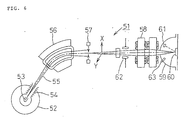
- FIG. 4 is a schematic view showing a principal portion of an ion beam analyzing apparatus according to a second preferred embodiment adapted to carry out the method of the present invention;
- FIG. 5a is a diagrammatic view schematically showing an entire ion beam analyzing apparatus according to a third preferred embodiment adapted to carry out the method of the present invention, and FIG. 5b is a diagrammatic view showing the screen of a cathode ray tube of the ion beam analyzing apparatus of FIG. 5a;
- FIG. 6 is a schematic view of an exemplary one of a conventional ion beam analyzing apparatus; and
- FIG. 7 is a schematic view of another exemplary one of a conventional ion beam analyzing apparatus.
- Referring first to FIG. 1a, there is shown an ion beam analyzing apparatus according to a first preferred embodiment adapted to carry out the method of the present invention. The ion beam analyzing apparatus shown is generally denoted at 1 and includes an
ion source 3 disposed in anion accelerator 2. A highenergy ion beam 5 is generated from theion source 3 of theion accelerator 2 and accelerated by anaccelerator tube 4 theion accelerator 2 has. The thus accelerated highenergy ion beam 5 is then restricted to several tens µm in diameter by an objective collimator 7 and then introduced into amass separator 6 of the Wien (E x B) type having a well known construction. While theion beam 5 passes themass separator 6, it is classified in ion type and energy. Then, theion beam 5 is deflected by deflectingelectrodes 12 and then introduced into two or three series of quadruple polemagnetic lenses 8. While theion beam 5 passes the quadruple polemagnetic lenses 8, it is converged at predetermined reduction ratios (constants) in the X and Y directions which depend upon the quadruple polemagnetic lenses 8, and is irradiated upon atarget 10 accommodated in avacuum chamber 9, that is, upon a specimen on thetarget 10, so that it forms a beam spot on the specimen. - Consequently, ions, electrons, photons and so forth are scattered and radiated from the specimen by a mutual action of the
incident ion beam 5 and thetarget 10. Those particles are detected by means of adetector 11 and asecondary electron detector 13 provided in thevacuum chamber 9, and a detection value detected by thesecondary electron detector 13 is inputted to animage apparatus 14 having such construction as described below. In particular, theimage apparatus 14 includes abeam position setter 14a, and anarithmetic unit 15 and anobject collimator controller 16, which will individually be hereinafter described, both interposed between thebeam position setter 14a andmotors 7m. Themotors 7m are provided for increasing or decreasing the dimensions of slits in the X and Y directions of the objective collimator 7, which has such a construction as hereinafter described, each between a minimum slit dimension 0 and a predetermined dimension. - The mechanisms for moving the objective collimator 7 in the X and Y directions have similar constructions to each other as can be seen well from FIG. 2, and therefore, the mechanism for moving the objective collimator 7 will be described as an example. Referring to FIG. 2, the objective collimator 7 includes a
base plate 7a, and a slit member supporting table 7b provided on thebase plate 7a and having an upper receiving table 7c and a lower receiving table 7d disposed horizontally in a vertically spaced relationship on a same side face thereof. Thebase plate 7a and the upper and lower receiving tables 7c and 7d have through-holes formed in a coaxial relationship therein. Amotor 7m in the form of a reversible motor is mounted on the receiving table 7c, and an output power shaft of themotor 7m extends through the through-hole in the upper receiving table 7c. A ball screw 7e is connected to an end of the output shaft of themotor 7m, and an end portion of the ball screw 7e is connected to an upper end of aslit operating rod 7g by way of a connecting element 7f. The connecting element 7f is fitted in the through-hole of the lower receiving table 7d and slidably moved in the through-hole by the ball screw 7e which is rotated by rotation of themotor 7m. Theslit operating rod 7g extends through the lower receiving table 7d and has an L-shapedslit member 7h securely mounted at a lower end thereof. Consequently, theslit operating rod 7g is slidably moved by sliding movement of the connecting element 7f caused by rotation of the bass screw 73, whereupon theslit member 7h is moved-back and forth in predetermined directions to increase or decrease the dimension of the slit of the objective collimator 7. - Another
slit member 7h for the Y direction is provided in an opposing relationship below theslit member 7h, and a slit is formed between ends of vertical portions of theslit members 7h. Theslit members 7h are synchronously moved toward and away from each other to vary the dimension of the slit between 0 and the predetermined value. Meanwhile, as described hereinabove, theslit members 7h for the X direction have the same construction as theslit members 7h for the Y direction described just above except that they are moved in the horizontal directions to vary the dimensions of a slit formed between them while theslit members 7h for the Y direction are moved in the vertical directions. - A block 7j is securely mounted on a face of each of the
slit members 7h remote from theslit operating rod 7g for theslit member 7h and extends perpendicularly to the advancing direction of theion beam 5. Amolybdenum rod 7k having the diameter of 10mm and the length of 10 mm is embedded in each of the blocks 7j. Themolybdenum rods 7k are disposed in a spaced relationship by a distance equal to the distance between theslit members 7h and serves as a slitdimension detecting section 7i. - Accordingly, the distance between the
slit members 7h, in short, the slit dimension, is detected from the distance between themolybdenum rods 7k. Meanwhile, theobjective collimator controller 16 interposed between thebeam position setter 14a and themotors 7m detects the slit dimension A in the X direction and the slit dimension B in the Y direction formed between theslit members 7h as they are driven to move by themotors 7m, and outputs the thus detected dimensions A and B to thearithmetic unit 15. - The
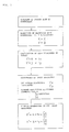
arithmetic unit 15 calculates actual dimensions X' and Y' of a beam spot formed on thetarget 10 from a reduction ratio fx in the X direction and another reduction ratio fy in the Y direction of theion beam 5 by the quadruple polemagnetic lenses 8. Thearithmetic unit 15 enlarges the thus calculated values X' and Y' at a predetermined rate and outputs resulted values of the enlargement to thebeam position setter 14a and also to a cathode ray tube (CRT) 14g so that the output values may be displayed on thecathode ray tube 14. By the way, while the actual dimensions X' and Y' of beam spots formed on the specimen on thetarget 10 are represented by X' = A x fx and Y' = B x fy, respectively, they actually are very small dimensions. Therefore, as illustrated in FIG. 3, the value X' is multiplied by a value obtained by division of the condition Cx of theimage apparatus 14 by the current scanning width Sx by the deflectingelectrodes 12 while the value Y' is multiplied by a value obtained by division of the condition Cy of theimage apparatus 14 by the current scanning width Sy by the deflectingelectrodes 12 to calculate X'' = A x fx(Cx/Sx) and Y" = B x fy(Cy/Sy), respectively, and an image having the thus enlarged dimensions X'' and Y'' is displayed as a beam spot mark T on thecathode ray tube 14g of theimage apparatus 14 as shown in FIG. 1b. - Subsequently, the procedure to inputting from the objective collimator 7 to the
cathode ray tube 14g of theimage apparatus 14 will be described with reference to FIG. 3. - At the first step, the
objective collimator controller 16 will be manually operated to activate themotors 7m so that theslit members 7h for the X and Y directions of the objective collimator 7 are moved by way of the ball screws 7e, connecting elements 7f, and slitoperating rods 7g. - At the second step, the slit dimension A in the X direction and the slit dimension B in the Y direction of the
slit members 7h from the slit distance 0 (closed slit condition) are detected by the slitdimension detecting sections 7i provided for theslit members 7h for the X and Y directions, respectively. - At the third step, the slit distance A and the slit distance B thus detected are multiplied by the reduction radio fx for the X direction and the reduction ratio fy for the Y direction of the quadruple pole
magnetic lenses 8, respectively, to calculate actual diameters of a spot of theion beam 5 formed on the surface of the specimen on thetarget 10, that is, X' = A x fx and Y' = B x fy, by means of thearithmetic unit 15. - At the fourth step, conditions of the
image apparatus 14, that is, dimensions (constants) Cx and Cy of the screen of thecathode ray tube 14g, are selected and the current scanning widths Sx and Sy of the deflectingelectrodes 12 in the X and Y directions are selected by thearithmetic unit 15. - At the fifth step, enlarged dimensions of the slit dimensions A and B enlarged at a predetermined ratio and given by X'' = A x fx x (Cx/Sx) and Y'' = B x fy x (Cy/Sy), respectively, are calculated by the
arithmetic unit 15, and an image of the enlarged dimensions are displayed as a graspable beam spot mark T on thecathode ray tube 14g of theimage apparatus 14 as shown in FIG. 1b. - In particular, the
motors 7m are driven by theobjective collimator controller 16, and the slit dimensions A and B from the respective slit distances 0 (closed conditions) are calculated by the slitdistance detecting sections 7i. Then, the slit dimensions A and B are multiplied by the reduction ratios of the quadruple polemagnetic lenses 8 which depend upon an optical layout dimension by thearithmetic unit 15 and inputted as dimensions of converged beams on thetarget 10 to thebeam position setter 14. Asweeping apparatus 14e for performing scanning of a beam for observation of a secondary electron image of the specimen provided on thetarget 10 displays on thecathode ray tube 14g as a secondary electron image an enlarged image of the surface of the specimen which is multiplied by a multiplication factor which depends upon the scanning width and the dimension of an image to be displayed on thecathode ray tube 14g. Further, in addition to the set beam position, a beam spot mark T having a rectangular profile wherein the dimensions in the X and Y directions of theion beam 5 converged on thetarget 10 are represented as X'' x Y'' is disposed on the secondary electron image of thecathode ray tube 14g as shown in FIG. 1b. - Subsequently, an operator will manually operate the manually operable mechanism of the
beam position setter 14a to move the beam spot mark T having the set slit dimensions and the ion beam position information upwardly or downwardly and leftwardly or rightwardly on the screen of thecathode ray tube 14g so as to adjust the beam spot mark T to a position at which the operator wants to measure a secondary electron image. Thus, for example, when the profile of a portion of the specimen on the micron order to be measured does not conform to the profile and the dimensions of the ion beam then, the objective collimator 7 is operated by theobjective collimator controller 16 to vary the slit dimensions A and B, and thereupon, the X and Y dimensions of the beam spot mark T displayed on the screen of thecathode ray tube 14g are automatically varied. Therefore, the beam spot mark T can be positioned at the profile of the specimen readily. Further, when the profile of the beam spot is adjusted in this manner, it can be adjusted to the maximum area of the portion of the specimen to be measured, and the amount of irradiation of the ion beam is increased as a whole. As a result, the advantage is provided that the time for analysis of a specimen is decreased and the efficiency of the analyzing operation is improved. - An ion beam analyzing apparatus according to a second preferred embodiment adapted to carry out the method of the present invention will be described subsequently with reference to FIG. 4 in which only part of the ion beam analyzing apparatus is shown. The ion beam analyzing apparatus of the present embodiment is a modification to and principally different from the ion beam analyzing apparatus of the first embodiment described above in that the deflecting
electrodes 12 are disposed at different locations as can be seen from FIGS. la and 4. More particularly, the deflectingelectrodes 12 are interposed between the quadruple polemagnetic lenses 8 and thevacuum chamber 9 similarly as in the conventional ion beam analyzing apparatus described hereinabove with reference to FIG. 7. Since the ion beam analyzing apparatus of the present embodiment has the same construction as the ion beam analyzing apparatus of the first embodiment except the locations of the deflectingelectrodes 12, it exhibits similar advantages to those of the ion beam analyzing apparatus of the first embodiment. - An ion beam analyzing apparatus according to a third preferred embodiment adapted to carry out the method of the present invention will be described subsequently with reference to FIGS. 5a and 5b. Also the ion beam analyzing apparatus of the present embodiment is a modification to the ion beam analyzing apparatus of the first embodiment but is different only in that it includes, in place of the
mass separator 6 of the EXB type for separating anion beam 5 in ion type and energy, adeflecting analyzing electromagnet 6 which is interposed between theion accelerator 2 and the objective collimator 7. - Accordingly, a high
energy ion beam 5 generated from theion source 3 of theion accelerator 2 and accelerated by theaccelerator tube 4 of theion accelerator 2 is deflected, while passing through thedeflecting analyzing electromagnet 6, normally by an angle of 15 degrees so that it is classified in ion type and energy. Subsequently, the highenergy ion beam 5 is restricted into a micro-beam by the objective collimator 7 and then passes a drift space of several meters and the deflectingelectrodes 12. Then, when the highenergy ion beam 5 passes the succeeding quadruple polemagnetic lenses 8, it is converged at predetermined reduction ratios in the X and Y directions, which depend upon the quadruple polemagnetic lenses 8, and then irradiated upon thetarget 10 accommodated in thevacuum chamber 9 so that it forms a spot on thetarget 10. - Then, enlarged dimensions of the slit dimensions A and B which are enlarged at predetermined ratios and given by X'' = A x fx x (Cx/Sx) and Y'' = B x fy x (Cy/Sy) are calculated by the
arithmetic unit 15 by way of the first to fifth steps described hereinabove with reference to FIG. 3. An image of the enlarge dimensions is displayed as a graspable beam spot mark T on thecathode ray tube 14g of theimage apparatus 14. Accordingly, the ion beam analyzing apparatus of the present embodiment exhibits similar advantages to those of the ion beam analyzing apparatus of the first embodiment described hereinabove. - It is to be noted that, while, in the ion beam analyzing apparatus of the third embodiment, the deflecting
electrodes 12 are interposed between the objective collimator 7 and the quadruple polemagnetic lenses 8 similarly as in the ion beam analyzing apparatus of the first embodiment, the deflectingelectrodes 12 may otherwise be interposed between the quadruple polemagnetic lenses 8 and thevacuum chamber 9 in a similar manner as in the conventional ion beam analyzing apparatus described hereinabove with reference to FIG. 7. - Having now fully described the invention, it will be apparent to one of ordinary skill in the art that many changes and modifications can be made thereto without departing from the scope of the invention as set forth herein.
Claims (4)
- An ion beam analyzing method for irradiating an ion beam upon a specimen to analyze a small area of the specimen comprising the steps ofgenerating ions from an ion source (3);accelerating said generated ions using an ion accelerator (2, 4) to form an ion beam (5);accommodating a specimen (10) to be analyzed in a vacuum chamber (9) including a secondary electron detector (13);varying the size of a slit of a slit device (7) in x and y directions of two perpendicular axes to restrict said ion beam (5) using an objective collimator (7) interposed between said ion accelerator (2, 4) and said vacuum chamber (9);converging and irradiating said ion beam (5) upon said specimen (10) in said vacuum chamber (9) to form a beam spot on said specimen (10) using a magnetic lens (8) interposed between said ion accelerator (2, 4) and said vacuum chamber (9);scanning said ion beam (5) on the specimen when a high frequency potential is applied thereto or a high frequency current is supplied thereto using a deflecting electrode device (12) disposed between said ion accelerator (2, 4) and said vacuum chamber (9);characterized by the further steps ofdisplaying the position of said beam spot and a detection signal detected by said secondary electron detector (13) in synchronism with said deflecting electrode device (12) as a secondary electron image using a display means (14);calculating the dimensions of said beam spot in accordance with size data of said slit of said slit device (7) using a calculating means (15); anddisplaying an image in accordance with the thus calculated dimensions.
- An ion beam analyzing method according to claim 1 being further characterized by the step of displaying the size data of said slit of said slit device using said display means (14).
- An ion beam analyzing method according to claim 1, characterized in that the dimensions X and Y of the beam spot in the x and y directions are calculated using said calculating means (15) according to the following equations:


- An ion beam analyzing method according to claim 1, characterized in that the dimensions X and Y with which the beam spot is to be displayed on said display means (14) in the x and y directions are calculated in accordance with the following equations:


Applications Claiming Priority (4)
| Application Number | Priority Date | Filing Date | Title |
|---|---|---|---|
| JP343358/91 | 1991-12-25 | ||
| JP34335891 | 1991-12-25 | ||
| JP310360/92 | 1992-11-19 | ||
| JP31036092A JP3235681B2 (en) | 1991-12-25 | 1992-11-19 | Ion beam analyzer |
Publications (2)
| Publication Number | Publication Date |
|---|---|
| EP0548899A1 EP0548899A1 (en) | 1993-06-30 |
| EP0548899B1 true EP0548899B1 (en) | 1996-03-13 |
Family
ID=26566283
Family Applications (1)
| Application Number | Title | Priority Date | Filing Date |
|---|---|---|---|
| EP92121751A Expired - Lifetime EP0548899B1 (en) | 1991-12-25 | 1992-12-21 | Ion beam analyzing method |
Country Status (4)
| Country | Link |
|---|---|
| US (1) | US5350920A (en) |
| EP (1) | EP0548899B1 (en) |
| JP (1) | JP3235681B2 (en) |
| DE (1) | DE69209028T2 (en) |
Families Citing this family (13)
| Publication number | Priority date | Publication date | Assignee | Title |
|---|---|---|---|---|
| US5854490A (en) * | 1995-10-03 | 1998-12-29 | Fujitsu Limited | Charged-particle-beam exposure device and charged-particle-beam exposure method |
| JP3544438B2 (en) * | 1996-09-30 | 2004-07-21 | セイコーインスツルメンツ株式会社 | Processing equipment using ion beam |
| JP3449198B2 (en) * | 1997-10-22 | 2003-09-22 | 日新電機株式会社 | Ion implanter |
| US6002208A (en) * | 1998-07-02 | 1999-12-14 | Advanced Ion Technology, Inc. | Universal cold-cathode type ion source with closed-loop electron drifting and adjustable ion-emitting slit |
| US6137110A (en) * | 1998-08-17 | 2000-10-24 | The United States Of America As Represented By The United States Department Of Energy | Focused ion beam source method and apparatus |
| JP3414337B2 (en) * | 1999-11-12 | 2003-06-09 | 日新電機株式会社 | Electromagnetic field lens control method and ion implantation apparatus |
| JP4148864B2 (en) * | 2003-09-26 | 2008-09-10 | 株式会社神戸製鋼所 | Sample analyzer |
| EP2498271B1 (en) * | 2003-10-20 | 2021-03-31 | ICT Integrated Circuit Testing Gesellschaft für Halbleiterprüftechnik mbH | Charged particle beam device with aperture |
| NL1031800C2 (en) * | 2006-05-11 | 2007-11-13 | Milabs B V | Detection device. |
| RU2395133C1 (en) * | 2009-03-10 | 2010-07-20 | Учреждение РАН Физико-технологический институт РАН | Source of high-speed neutral particles |
| JP6641011B2 (en) * | 2015-11-30 | 2020-02-05 | エーエスエムエル ネザーランズ ビー.ブイ. | Equipment for multiple charged particle beams |
| CN108387924A (en) * | 2018-03-08 | 2018-08-10 | 西北核技术研究所 | A kind of high-precision beam energy analysis slit arrangement |
| WO2022145263A1 (en) * | 2020-12-28 | 2022-07-07 | 博文 福山 | Ion beam analysis device |
Family Cites Families (6)
| Publication number | Priority date | Publication date | Assignee | Title |
|---|---|---|---|---|
| US4055770A (en) * | 1972-03-15 | 1977-10-25 | C.G.R.-Mev. | Collimator arrangement for a beam of accelerated charged particles |
| FR2410359A1 (en) * | 1977-11-28 | 1979-06-22 | Anvar | MOBILE EXTRACTION ELECTRODE FOR ION SOURCE |
| US4761559A (en) * | 1986-09-24 | 1988-08-02 | Eaton Corporation | Ion beam implantation display method and apparatus |
| JPH02295040A (en) * | 1989-05-10 | 1990-12-05 | Hitachi Ltd | Focused ion beam device |
| US5063294A (en) * | 1989-05-17 | 1991-11-05 | Kabushiki Kaisha Kobe Seiko Sho | Converged ion beam apparatus |
| GB2233124B (en) * | 1989-06-06 | 1994-02-09 | Mitsubishi Electric Corp | Ion implantation apparatus |
-
1992
- 1992-11-19 JP JP31036092A patent/JP3235681B2/en not_active Expired - Lifetime
- 1992-12-21 EP EP92121751A patent/EP0548899B1/en not_active Expired - Lifetime
- 1992-12-21 DE DE69209028T patent/DE69209028T2/en not_active Expired - Fee Related
- 1992-12-22 US US07/994,953 patent/US5350920A/en not_active Expired - Lifetime
Also Published As
| Publication number | Publication date |
|---|---|
| EP0548899A1 (en) | 1993-06-30 |
| DE69209028T2 (en) | 1996-09-12 |
| JP3235681B2 (en) | 2001-12-04 |
| DE69209028D1 (en) | 1996-04-18 |
| US5350920A (en) | 1994-09-27 |
| JPH05234559A (en) | 1993-09-10 |
Similar Documents
| Publication | Publication Date | Title |
|---|---|---|
| US7385196B2 (en) | Method and scanning electron microscope for measuring width of material on sample | |
| Grime et al. | The Oxford submicron nuclear microscopy facility | |
| US6531697B1 (en) | Method and apparatus for scanning transmission electron microscopy | |
| US5350920A (en) | Ion beam analyzing apparatus | |
| US8080789B2 (en) | Sample dimension measuring method and scanning electron microscope | |
| EP3761016B1 (en) | Methods and systems for acquiring electron backscatter diffraction patterns | |
| KR102940828B1 (en) | Method and system for imaging three-dimensional feature | |
| EP1238405B1 (en) | Method and system for the examination of specimen using a charged particle beam | |
| US5118941A (en) | Apparatus and method for locating target area for electron microanalysis | |
| US20090224170A1 (en) | Scanning electron microscope | |
| US20200393392A1 (en) | Method of examining a sample using a charged particle microscope | |
| US6770867B2 (en) | Method and apparatus for scanned instrument calibration | |
| Matsuyama et al. | Automation of multi-modal beam focusing of an MeV sub-microprobe for ion beam analysis | |
| JP2716997B2 (en) | Cross-sectional shape measurement method, cross-sectional shape comparison inspection method and their devices | |
| JP3499690B2 (en) | Charged particle microscope | |
| US20230078510A1 (en) | Method for focusing and operating a particle beam microscope | |
| JP2006172919A (en) | Scanning electron microscope with three-dimensional shape analysis function | |
| US10998166B2 (en) | System and method for beam position visualization | |
| JP2004265879A (en) | Element mapping apparatus, scanning transmission electron microscope, and element mapping method | |
| KR960000808B1 (en) | Secondary ion mass analyzer | |
| EP0737858A1 (en) | Method and apparatus for adjusting electron-beam device | |
| EP4310485B1 (en) | Method of examining a sample using a charged particle microscope | |
| JP7743387B2 (en) | Analysis method and analysis device | |
| Kinomura et al. | RBS analysis of beam-processed microarea by focused MeV ion beam | |
| EP1428006B1 (en) | Method and apparatus for scanned instrument calibration |
Legal Events
| Date | Code | Title | Description |
|---|---|---|---|
| PUAI | Public reference made under article 153(3) epc to a published international application that has entered the european phase |
Free format text: ORIGINAL CODE: 0009012 |
|
| 17P | Request for examination filed |
Effective date: 19921221 |
|
| AK | Designated contracting states |
Kind code of ref document: A1 Designated state(s): DE FR GB |
|
| 17Q | First examination report despatched |
Effective date: 19940425 |
|
| GRAH | Despatch of communication of intention to grant a patent |
Free format text: ORIGINAL CODE: EPIDOS IGRA |
|
| GRAA | (expected) grant |
Free format text: ORIGINAL CODE: 0009210 |
|
| AK | Designated contracting states |
Kind code of ref document: B1 Designated state(s): DE FR GB |
|
| ET | Fr: translation filed | ||
| REF | Corresponds to: |
Ref document number: 69209028 Country of ref document: DE Date of ref document: 19960418 |
|
| PLBE | No opposition filed within time limit |
Free format text: ORIGINAL CODE: 0009261 |
|
| STAA | Information on the status of an ep patent application or granted ep patent |
Free format text: STATUS: NO OPPOSITION FILED WITHIN TIME LIMIT |
|
| 26N | No opposition filed | ||
| REG | Reference to a national code |
Ref country code: GB Ref legal event code: IF02 |
|
| PGFP | Annual fee paid to national office [announced via postgrant information from national office to epo] |
Ref country code: FR Payment date: 20031210 Year of fee payment: 12 |
|
| PGFP | Annual fee paid to national office [announced via postgrant information from national office to epo] |
Ref country code: GB Payment date: 20031217 Year of fee payment: 12 |
|
| PGFP | Annual fee paid to national office [announced via postgrant information from national office to epo] |
Ref country code: DE Payment date: 20040102 Year of fee payment: 12 |
|
| PG25 | Lapsed in a contracting state [announced via postgrant information from national office to epo] |
Ref country code: GB Free format text: LAPSE BECAUSE OF NON-PAYMENT OF DUE FEES Effective date: 20041221 |
|
| PG25 | Lapsed in a contracting state [announced via postgrant information from national office to epo] |
Ref country code: DE Free format text: LAPSE BECAUSE OF NON-PAYMENT OF DUE FEES Effective date: 20050701 |
|
| GBPC | Gb: european patent ceased through non-payment of renewal fee |
Effective date: 20041221 |
|
| PG25 | Lapsed in a contracting state [announced via postgrant information from national office to epo] |
Ref country code: FR Free format text: LAPSE BECAUSE OF NON-PAYMENT OF DUE FEES Effective date: 20050831 |
|
| REG | Reference to a national code |
Ref country code: FR Ref legal event code: ST |