EP0548566B1 - Device for further processing after copying - Google Patents
Device for further processing after copying Download PDFInfo
- Publication number
- EP0548566B1 EP0548566B1 EP92119995A EP92119995A EP0548566B1 EP 0548566 B1 EP0548566 B1 EP 0548566B1 EP 92119995 A EP92119995 A EP 92119995A EP 92119995 A EP92119995 A EP 92119995A EP 0548566 B1 EP0548566 B1 EP 0548566B1
- Authority
- EP
- European Patent Office
- Prior art keywords
- sheet
- sheets
- path
- copying
- holding means
- Prior art date
- Legal status (The legal status is an assumption and is not a legal conclusion. Google has not performed a legal analysis and makes no representation as to the accuracy of the status listed.)
- Expired - Lifetime
Links
- 230000032258 transport Effects 0.000 claims description 88
- 238000000034 method Methods 0.000 claims description 41
- 238000001514 detection method Methods 0.000 claims description 30
- 238000007599 discharging Methods 0.000 claims description 6
- 230000001360 synchronised effect Effects 0.000 claims description 2
- 108091008695 photoreceptors Proteins 0.000 description 11
- 230000000284 resting effect Effects 0.000 description 11
- 239000011521 glass Substances 0.000 description 5
- 230000003287 optical effect Effects 0.000 description 3
- 238000004080 punching Methods 0.000 description 3
- 238000003825 pressing Methods 0.000 description 2
- 238000000926 separation method Methods 0.000 description 2
- 230000003068 static effect Effects 0.000 description 2
- 230000001174 ascending effect Effects 0.000 description 1
- 239000000463 material Substances 0.000 description 1
- 238000011144 upstream manufacturing Methods 0.000 description 1
Images











Classifications
-
- G—PHYSICS
- G03—PHOTOGRAPHY; CINEMATOGRAPHY; ANALOGOUS TECHNIQUES USING WAVES OTHER THAN OPTICAL WAVES; ELECTROGRAPHY; HOLOGRAPHY
- G03G—ELECTROGRAPHY; ELECTROPHOTOGRAPHY; MAGNETOGRAPHY
- G03G15/00—Apparatus for electrographic processes using a charge pattern
- G03G15/65—Apparatus which relate to the handling of copy material
- G03G15/6538—Devices for collating sheet copy material, e.g. sorters, control, copies in staples form
- G03G15/6541—Binding sets of sheets, e.g. by stapling, glueing
-
- B—PERFORMING OPERATIONS; TRANSPORTING
- B42—BOOKBINDING; ALBUMS; FILES; SPECIAL PRINTED MATTER
- B42C—BOOKBINDING
- B42C1/00—Collating or gathering sheets combined with processes for permanently attaching together sheets or signatures or for interposing inserts
- B42C1/12—Machines for both collating or gathering and permanently attaching together the sheets or signatures
-
- B—PERFORMING OPERATIONS; TRANSPORTING
- B65—CONVEYING; PACKING; STORING; HANDLING THIN OR FILAMENTARY MATERIAL
- B65H—HANDLING THIN OR FILAMENTARY MATERIAL, e.g. SHEETS, WEBS, CABLES
- B65H29/00—Delivering or advancing articles from machines; Advancing articles to or into piles
- B65H29/26—Delivering or advancing articles from machines; Advancing articles to or into piles by dropping the articles
- B65H29/32—Delivering or advancing articles from machines; Advancing articles to or into piles by dropping the articles from pneumatic, e.g. suction, carriers
-
- B—PERFORMING OPERATIONS; TRANSPORTING
- B65—CONVEYING; PACKING; STORING; HANDLING THIN OR FILAMENTARY MATERIAL
- B65H—HANDLING THIN OR FILAMENTARY MATERIAL, e.g. SHEETS, WEBS, CABLES
- B65H29/00—Delivering or advancing articles from machines; Advancing articles to or into piles
- B65H29/58—Article switches or diverters
-
- B—PERFORMING OPERATIONS; TRANSPORTING
- B65—CONVEYING; PACKING; STORING; HANDLING THIN OR FILAMENTARY MATERIAL
- B65H—HANDLING THIN OR FILAMENTARY MATERIAL, e.g. SHEETS, WEBS, CABLES
- B65H29/00—Delivering or advancing articles from machines; Advancing articles to or into piles
- B65H29/58—Article switches or diverters
- B65H29/60—Article switches or diverters diverting the stream into alternative paths
-
- B—PERFORMING OPERATIONS; TRANSPORTING
- B65—CONVEYING; PACKING; STORING; HANDLING THIN OR FILAMENTARY MATERIAL
- B65H—HANDLING THIN OR FILAMENTARY MATERIAL, e.g. SHEETS, WEBS, CABLES
- B65H31/00—Pile receivers
- B65H31/04—Pile receivers with movable end support arranged to recede as pile accumulates
- B65H31/08—Pile receivers with movable end support arranged to recede as pile accumulates the articles being piled one above another
- B65H31/10—Pile receivers with movable end support arranged to recede as pile accumulates the articles being piled one above another and applied at the top of the pile
-
- B—PERFORMING OPERATIONS; TRANSPORTING
- B65—CONVEYING; PACKING; STORING; HANDLING THIN OR FILAMENTARY MATERIAL
- B65H—HANDLING THIN OR FILAMENTARY MATERIAL, e.g. SHEETS, WEBS, CABLES
- B65H31/00—Pile receivers
- B65H31/30—Arrangements for removing completed piles
- B65H31/3081—Arrangements for removing completed piles by acting on edge of the pile for moving it along a surface, e.g. by pushing
-
- G—PHYSICS
- G03—PHOTOGRAPHY; CINEMATOGRAPHY; ANALOGOUS TECHNIQUES USING WAVES OTHER THAN OPTICAL WAVES; ELECTROGRAPHY; HOLOGRAPHY
- G03G—ELECTROGRAPHY; ELECTROPHOTOGRAPHY; MAGNETOGRAPHY
- G03G15/00—Apparatus for electrographic processes using a charge pattern
- G03G15/65—Apparatus which relate to the handling of copy material
- G03G15/6538—Devices for collating sheet copy material, e.g. sorters, control, copies in staples form
-
- G—PHYSICS
- G03—PHOTOGRAPHY; CINEMATOGRAPHY; ANALOGOUS TECHNIQUES USING WAVES OTHER THAN OPTICAL WAVES; ELECTROGRAPHY; HOLOGRAPHY
- G03G—ELECTROGRAPHY; ELECTROPHOTOGRAPHY; MAGNETOGRAPHY
- G03G15/00—Apparatus for electrographic processes using a charge pattern
- G03G15/65—Apparatus which relate to the handling of copy material
- G03G15/6552—Means for discharging uncollated sheet copy material, e.g. discharging rollers, exit trays
-
- G—PHYSICS
- G03—PHOTOGRAPHY; CINEMATOGRAPHY; ANALOGOUS TECHNIQUES USING WAVES OTHER THAN OPTICAL WAVES; ELECTROGRAPHY; HOLOGRAPHY
- G03G—ELECTROGRAPHY; ELECTROPHOTOGRAPHY; MAGNETOGRAPHY
- G03G15/00—Apparatus for electrographic processes using a charge pattern
- G03G15/65—Apparatus which relate to the handling of copy material
- G03G15/6582—Special processing for irreversibly adding or changing the sheet copy material characteristics or its appearance, e.g. stamping, annotation printing, punching
-
- B—PERFORMING OPERATIONS; TRANSPORTING
- B65—CONVEYING; PACKING; STORING; HANDLING THIN OR FILAMENTARY MATERIAL
- B65H—HANDLING THIN OR FILAMENTARY MATERIAL, e.g. SHEETS, WEBS, CABLES
- B65H2301/00—Handling processes for sheets or webs
- B65H2301/40—Type of handling process
- B65H2301/42—Piling, depiling, handling piles
- B65H2301/421—Forming a pile
- B65H2301/4212—Forming a pile of articles substantially horizontal
-
- B—PERFORMING OPERATIONS; TRANSPORTING
- B65—CONVEYING; PACKING; STORING; HANDLING THIN OR FILAMENTARY MATERIAL
- B65H—HANDLING THIN OR FILAMENTARY MATERIAL, e.g. SHEETS, WEBS, CABLES
- B65H2301/00—Handling processes for sheets or webs
- B65H2301/40—Type of handling process
- B65H2301/42—Piling, depiling, handling piles
- B65H2301/421—Forming a pile
- B65H2301/4213—Forming a pile of a limited number of articles, e.g. buffering, forming bundles
-
- B—PERFORMING OPERATIONS; TRANSPORTING
- B65—CONVEYING; PACKING; STORING; HANDLING THIN OR FILAMENTARY MATERIAL
- B65H—HANDLING THIN OR FILAMENTARY MATERIAL, e.g. SHEETS, WEBS, CABLES
- B65H2405/00—Parts for holding the handled material
- B65H2405/10—Cassettes, holders, bins, decks, trays, supports or magazines for sheets stacked substantially horizontally
- B65H2405/11—Parts and details thereof
- B65H2405/111—Bottom
- B65H2405/1116—Bottom with means for changing geometry
-
- B—PERFORMING OPERATIONS; TRANSPORTING
- B65—CONVEYING; PACKING; STORING; HANDLING THIN OR FILAMENTARY MATERIAL
- B65H—HANDLING THIN OR FILAMENTARY MATERIAL, e.g. SHEETS, WEBS, CABLES
- B65H2406/00—Means using fluid
- B65H2406/30—Suction means
- B65H2406/32—Suction belts
- B65H2406/323—Overhead suction belt, i.e. holding material against gravity
-
- B—PERFORMING OPERATIONS; TRANSPORTING
- B65—CONVEYING; PACKING; STORING; HANDLING THIN OR FILAMENTARY MATERIAL
- B65H—HANDLING THIN OR FILAMENTARY MATERIAL, e.g. SHEETS, WEBS, CABLES
- B65H2511/00—Dimensions; Position; Numbers; Identification; Occurrences
- B65H2511/20—Location in space
- B65H2511/21—Angle
- B65H2511/214—Inclination
-
- B—PERFORMING OPERATIONS; TRANSPORTING
- B65—CONVEYING; PACKING; STORING; HANDLING THIN OR FILAMENTARY MATERIAL
- B65H—HANDLING THIN OR FILAMENTARY MATERIAL, e.g. SHEETS, WEBS, CABLES
- B65H2511/00—Dimensions; Position; Numbers; Identification; Occurrences
- B65H2511/40—Identification
- B65H2511/414—Identification of mode of operation
-
- B—PERFORMING OPERATIONS; TRANSPORTING
- B65—CONVEYING; PACKING; STORING; HANDLING THIN OR FILAMENTARY MATERIAL
- B65H—HANDLING THIN OR FILAMENTARY MATERIAL, e.g. SHEETS, WEBS, CABLES
- B65H2511/00—Dimensions; Position; Numbers; Identification; Occurrences
- B65H2511/50—Occurence
- B65H2511/51—Presence
-
- B—PERFORMING OPERATIONS; TRANSPORTING
- B65—CONVEYING; PACKING; STORING; HANDLING THIN OR FILAMENTARY MATERIAL
- B65H—HANDLING THIN OR FILAMENTARY MATERIAL, e.g. SHEETS, WEBS, CABLES
- B65H2513/00—Dynamic entities; Timing aspects
- B65H2513/50—Timing
-
- B—PERFORMING OPERATIONS; TRANSPORTING
- B65—CONVEYING; PACKING; STORING; HANDLING THIN OR FILAMENTARY MATERIAL
- B65H—HANDLING THIN OR FILAMENTARY MATERIAL, e.g. SHEETS, WEBS, CABLES
- B65H2801/00—Application field
- B65H2801/24—Post -processing devices
- B65H2801/27—Devices located downstream of office-type machines
-
- G—PHYSICS
- G03—PHOTOGRAPHY; CINEMATOGRAPHY; ANALOGOUS TECHNIQUES USING WAVES OTHER THAN OPTICAL WAVES; ELECTROGRAPHY; HOLOGRAPHY
- G03G—ELECTROGRAPHY; ELECTROPHOTOGRAPHY; MAGNETOGRAPHY
- G03G2215/00—Apparatus for electrophotographic processes
- G03G2215/00362—Apparatus for electrophotographic processes relating to the copy medium handling
- G03G2215/00367—The feeding path segment where particular handling of the copy medium occurs, segments being adjacent and non-overlapping. Each segment is identified by the most downstream point in the segment, so that for instance the segment labelled "Fixing device" is referring to the path between the "Transfer device" and the "Fixing device"
- G03G2215/00417—Post-fixing device
- G03G2215/00426—Post-treatment device adding qualities to the copy medium product
-
- G—PHYSICS
- G03—PHOTOGRAPHY; CINEMATOGRAPHY; ANALOGOUS TECHNIQUES USING WAVES OTHER THAN OPTICAL WAVES; ELECTROGRAPHY; HOLOGRAPHY
- G03G—ELECTROGRAPHY; ELECTROPHOTOGRAPHY; MAGNETOGRAPHY
- G03G2215/00—Apparatus for electrophotographic processes
- G03G2215/00362—Apparatus for electrophotographic processes relating to the copy medium handling
- G03G2215/00789—Adding properties or qualities to the copy medium
- G03G2215/00818—Punch device
-
- G—PHYSICS
- G03—PHOTOGRAPHY; CINEMATOGRAPHY; ANALOGOUS TECHNIQUES USING WAVES OTHER THAN OPTICAL WAVES; ELECTROGRAPHY; HOLOGRAPHY
- G03G—ELECTROGRAPHY; ELECTROPHOTOGRAPHY; MAGNETOGRAPHY
- G03G2215/00—Apparatus for electrophotographic processes
- G03G2215/00362—Apparatus for electrophotographic processes relating to the copy medium handling
- G03G2215/00789—Adding properties or qualities to the copy medium
- G03G2215/00822—Binder, e.g. glueing device
- G03G2215/00827—Stapler
-
- G—PHYSICS
- G03—PHOTOGRAPHY; CINEMATOGRAPHY; ANALOGOUS TECHNIQUES USING WAVES OTHER THAN OPTICAL WAVES; ELECTROGRAPHY; HOLOGRAPHY
- G03G—ELECTROGRAPHY; ELECTROPHOTOGRAPHY; MAGNETOGRAPHY
- G03G2215/00—Apparatus for electrophotographic processes
- G03G2215/00362—Apparatus for electrophotographic processes relating to the copy medium handling
- G03G2215/00886—Sorting or discharging
- G03G2215/00911—Detection of copy amount or presence in discharge tray
-
- Y—GENERAL TAGGING OF NEW TECHNOLOGICAL DEVELOPMENTS; GENERAL TAGGING OF CROSS-SECTIONAL TECHNOLOGIES SPANNING OVER SEVERAL SECTIONS OF THE IPC; TECHNICAL SUBJECTS COVERED BY FORMER USPC CROSS-REFERENCE ART COLLECTIONS [XRACs] AND DIGESTS
- Y10—TECHNICAL SUBJECTS COVERED BY FORMER USPC
- Y10S—TECHNICAL SUBJECTS COVERED BY FORMER USPC CROSS-REFERENCE ART COLLECTIONS [XRACs] AND DIGESTS
- Y10S414/00—Material or article handling
- Y10S414/10—Associated with forming or dispersing groups of intersupporting articles, e.g. stacking patterns
- Y10S414/102—Associated with forming or dispersing groups of intersupporting articles, e.g. stacking patterns including support for group
- Y10S414/103—Vertically shiftable
- Y10S414/105—Shifted by article responsive means
Definitions
- the present invention relates to a device for further processing after copying, provided in image forming apparatuses such as copying machines, laser printers, etc., such process being the binding and/or punching of a plurality of copied sheets.
- the automatic document feeder is placed on a document tray of the copying machine, for example, for transporting a plurality of documents one by one onto the document tray of the copying machine.
- the device for further processing after copying is for carrying out a process after copying, such as stapling, punching, etc., on every predetermined number of sheets fed from the copying machine.
- the device disclosed in Japanese Laid-Open Publication 144370/1990 (Tokukaihei 2-144370) corresponding to EP-A-0 371 403 as an example of the conventional device for further processing after copying has the following arrangement.
- Fig. 26(a) first, the copied sheets S being transported from the side of a main body 301 are stacked on a stapler plate 302 where the copied sheets S are aligned. Then, the sheets S are bound by a stapler 303 provided within the device. Thereafter, the bound set of sheets S is sandwiched between discharge rollers 304 and 305 to be discharged onto a discharge tray 306.
- the device is also provided with first and second transport paths 308a and 308b, whose lengths are different, placed between an entry opening 307 for the sheets S on the side of the main body 301 and the stapler plate 302. Furthermore, a deflector 309 is provided at a branch point between the first and the second transport paths 308a and 308b so as to switch the transport path for the sheet either to the first path 308a or to the second path 308b.
- the first path 308a is set longer than the second path 308b, and the downstream of the first path 308a joins again the second path 308b.
- a discharge roller 310 is provided at the end of the path for releasing the sheets S onto the stapler plate 302 through the path.
- the device for further processing after copying operates as follows. While a predetermined binding operation is carried out on a first set of sheets S on the stapler plate 302, a first sheet S 1 of the next set fed from the main body 301 is transported through the first path 308a, and a second sheet S 2 of the next set is transported through the second path 308b. With this arrangement, the second sheet S 2 is stacked on the first sheet S 1 so as to be discharged onto the stapler plate 302 through the discharge roller 310 at the same time as shown in Fig. 26(b). As a result, the time loss due to the time required for binding the first set of sheets S can be reduced, thereby permitting a faster binding process.
- the first and the second sheets S 1 and S 2 released onto the stapler plate 302 at the same time are sandwiched between the rollers 304 and 305.
- the ends of the sheets S 1 and S 2 are respectively aligned by rotating the discharge roller 305 in an opposite direction to its rotation direction for discharging the sheets S.
- the first transport path 308a is set longer than the second transport path 308b so as to release the first and the second sheets S 1 and S 2 onto the stapler plate 302 at the same time.
- This arrangement enables a faster process for binding a plurality of sheets S .
- the transport paths must be set long in order to maintain the above arrangement. This makes the size of the device larger.
- the first and the second transport paths 308a and 308b may be curved instead of being straight.
- this makes the transport paths for the sheets S complicated, and is likely to create the problem of lowering the quality of the bound set of sheets S by being creased.
- the sheets S 1 and S 2 are sandwiched between the rollers 304 and 305, and are aligned by rotating the discharge roller 305 in the opposite direction.
- it is difficult to precisely align a stack of the sheets S 1 and S 2 thereby lowering the quality of the bound set of sheets S .
- the device for further processing after copying having the above configuration is shown in Figs. 27(a)(b) and Fig. 28.
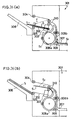
- the staple mode wherein the sheets S being transported from the side of the main body 301 are bound before being discharged out of the device, the copied sheets S , which have been transported from the side of the main body 301 through the transport path 311, are aligned on the stapler plate 312 as shown in Fig. 27(a). Then, the sheets S are bound by the stapler 313 provided within the device, thereafter the bound set of sheets S is discharged onto a discharge tray 316 using the rotation of a discharge roller 314 and the forward motion of a push-out member 315.
- the sheets S are discharged as follows. As shown in Fig. 27(b), a driven roller 317 placed above the discharge roller 314 is rotated so as to be in contact with the discharge roller 314. Then, the copied sheets S being transported through the transport path 311 from the side of the main body 301 are sandwiched between the rollers 314 and 317 to be directly discharged onto the discharge tray 316.
- the device shown in Fig. 28 is provided with an offset tray 324 for placing thereon the sheets S in the offset mode separately from a staple tray 329 for placing thereon the sheets S in the staple mode.
- the offset mode with a path switching operation of the deflector 322, first the sheets S being transported from the side of the main body 301 are passed through the first transport path 321a. Then, the sheets S are sandwiched between the discharge rollers 323 to be discharged onto the discharge tray 324.
- the staple mode with the path switching operation of the deflector 322, the sheets S being transported through the second transport path 321b are aligned on the stapler plate 325. Then, the sheets S are bound by the stapler 326 provided in the device, and are discharged onto the discharge tray 329 with the rotation of the discharge roller 327 and the forward motion of the push-out member 328.
- the sheet transporting direction in the offset mode is different from the sheet transporting direction in the staple mode, and the sheets S are discharged onto the same discharge tray 316 in both modes.
- the tray angle of the discharge tray 316 is constant, the ability to discharge sufficiently in both modes is difficult to be obtained.
- there is a level difference between the discharge roller 314 and the stapler plate 312 which causes the buckling and the creasing of the bound set of sheets S (Fig. 29).
- the tray angles are separately set for the trays 324 and 329 so as to satisfy the ability to discharge in both modes.
- the relative positions between the stapler tray 329 and the stapler plate 325 are not improved, the problem that the quality of the sheets is lowered due to the creasing of the bound set of sheets S still exists.
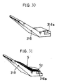
- the discharge tray 316 of the device shown in Figs. 27(a)(b) has a recessed portion 316a shown in Fig. 30 at the corner on the side of the device so that the stapled corners St of the bound set of sheets S drop by the dead weight of the corners St into the recessed portion 316a (Fig 31.). In this way, the preciseness in aligning the bound sets of sheets S on the discharge tray 316 can be improved.
- the alignment of the bound sets of sheets S on the discharge tray 316 can be improved by making the stapled corners St of the bound sets of sheets S drop into the recessed portion 316a by the dead weight of the corners St .
- the number of the corners St which drop into the recessed portion 316a differs depending on the number of the bound sets of sheets S to be placed on the discharge tray 316 and on the material used for the sheets S .
- the stapled corners St may be pushed back, which reduces the preciseness in aligning the bound sets of sheets S .
- the acceptable number of the stapled corners St to be dropped into the recessed portion 316a may be slightly improved by making larger the area of the recessed portion 316a.
- the area of the recessed portion 316a to be formed on the discharge tray 316 also has a limit. Therefore, it is difficult to accurately drop the stapled corners St into the recessed portion 316a.
- EP-A-315 734 A similar device of prior art is disclosed by EP-A-315 734.
- An object of the present invention is to provide a device for further processing after copying which permits a plurality of sheets to be processed in a shorter time.
- the device for further processing after copying in accordance with the invention includes the features of appended claim 1.
- Fig. 1 is a longitudinal sectional view showing a copying machine adopted in an embodiment of the present invention.
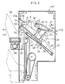
- Fig. 2 is a longitudinal sectional view showing the device for further processing after copying contained in the copying machine.
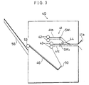
- Fig. 3 is an explanatory view showing each sheet detection switch provided along a transport path of the device for further processing after copying.
- Fig. 4 is an explanatory view showing a sheet detection switch composed of discharge rollers of the device for further processing after copying.
- Fig. 5 is a perspective view showing an actuator provided on the discharge roller.
- Figs. 6(a)(b) are explanatory views respectively showing upper limit detecting operations for the discharge tray by the actuator.
- Fig. 7 is a perspective view showing a recessed portion formed on the discharge tray.
- Fig. 8 is a longitudinal sectional view showing a spring provided on the discharge tray.
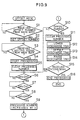
- Fig. 9 is a flow chart showing a process in an offset mode with a device for further processing after copying.
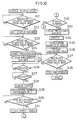
- Fig. 10 is a flow chart showing a process in a single staple mode with a device for further processing after copying.
- Fig. 11 is a flow chart showing a part of a process in a multiple staple mode with the device for further processing after copying.
- Fig. 12 is a flow chart showing a part of a process in a multiple staple mode with the device for further processing after copying.
- Fig. 13 is a flow chart showing a part of a process in a multiple staple mode with the device for further processing after copying.
- Fig. 14 is a flow chart showing a part of a process in a multiple staple mode with the device for further processing after copying.
- Fig. 15 is a flow chart showing a part of a process in a multiple staple mode with the device for further processing after copying.
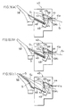
- Figs. 16(a)(b)(c) are explanatory views respectively showing sheet transporting operations through the transport path in the multiple staple mode.
- Figs. 17(a)(b)(c) are explanatory views respectively showing bound sheets aligning operation on the discharge tray in the multiple staple mode.
- Fig. 18 is a perspective view showing a plurality sets of bound sheets being stacked.
- Fig. 19 is a perspective view showing the bound sheets stacked on the discharge tray.
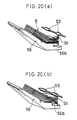
- Figs. 20(a)(b) are explanatory views respectively showing the bound sheets sandwiched between the discharge roller and the discharge tray.
- Figs. 21(a)(b) are explanatory views respectively showing a tray angle between a support face and a resting face, which varies depending on the volume of the bound sheets to be stacked on the discharge tray.
- Fig. 22 is an explanatory view showing a buckling of the bound sheets on the discharge tray due to a level difference between the support face and the resting face.
- Fig. 23 is a longitudinal sectional view showing a sponge roller capable of rotating around the rotation axis of the discharge roller.
- Fig. 24 is an explanatory view showing an angle change means composed of a cam unit.
- Fig. 25 is an explanatory view showing an angle change means composed of a crank unit.
- Figs. 26(a)(b) are explanatory views respectively showing sheet transporting operations through the transport path in the conventional device for processing after copying.
- Fig. 27(a) is an explanatory view showing a process in the staple mode with the conventional device for further processing after copying.
- Fig. 27(b) is an explanatory view showing a process in an offset mode with the conventional device for further processing after copying.
- Fig. 28 is a longitudinal sectional view showing another conventional device for further processing after copying.
- Fig. 29 is an explanatory view showing the state where the sheets are discharged onto the conventional discharge tray.
- Fig. 30 is a perspective view showing the conventional discharge tray having a recessed portion.
- Fig. 31 is a perspective view showing the state where the complete set stacked on the discharge tray of Fig. 93.
- the copying machine adopted in the present embodiment has a main body 1 which copies an image on a document M to a sheet S . Further, a document feeder 30 is provided above the main body 1, which transports the document M to an exposure area 2 formed on the top surface of the main body 1.
- a glass plate 3 having the exposure area 2 formed on the surface thereof is placed on the upper side of the main body 1. Further, an optical system 9 and a photoreceptor drum 10 are placed under the glass plate 3.
- the optical system 9 includes a light source 4, mirrors 5, 6, and 7, and a lens 8.
- the optical system 9 is provided for scanning the document M using a light emitted from the light source 4, the document M being transported to the exposure area 2 by the document feeder 30 (to be described later). Further, a reflected light is projected onto an exposure point A on the surface of the photoreceptor drum 10 through mirrors 5, 6 and 7, and the lens 8.
- a static latent image is formed on the surface of the photoreceptor drum 10 which is uniformly charged by a main charger unit 11 (to be described later), the static latent image corresponding to the image on the document M .
- a main charger unit 11, a developer unit 12, a transfer charger 13, and a separation charger 14 are provided along the circumference of the photoreceptor drum 10. As described, the main charger unit 11 charges the surface of the photoreceptor drum 10 to a predetermined electric potential. The developer unit 12 develops the electrostatic latent image formed on the surface of the photoreceptor drum 10 to be a toner image. Then, the transfer charger 13 transfers the toner image onto the sheet S which has been transported through a sheet transport path 15 (to be described later). In addition, the separation charger 14 is provided for separating the sheet S, whereon the toner image is to be transferred, from the photoreceptor drum 10.
- a sheet transport path 15 is provided under the photoreceptor drum 10, for transporting the sheets S , whereon the toner image is to be transferred. Further, a feed board 19, a feed cassette 20, and a feed deck 21 are placed on the upstream of the sheet transport path 15, respectively provided with feed rollers 16, 17 and 18. It is arranged such that the sheets S placed on the feed plate 19 or the feed deck 21, or the sheets S stored in the feed cassette 20 are fed to the photoreceptor drum 10 through the sheet transport path 15. On the downstream of the sheet transport path 15, a transport belt 22 and a fuser 23 are provided. The transfer belt 22 transports the sheet S whereon the toner image has been transferred. The toner image is made permanent on the sheet S by the fuser 23.
- a deflector 24 is provided by which a feeding path of the sheet is branched into both a path connected to a device 40 for further processing after copying (to be described later), and a re-transport path 25.
- the re-transport path 25 serves as a recirculation path through which the sheet S , whereon the toner image has been transferred by the photoreceptor drum 10, is transported again to the photoreceptor drum 10.
- an intermediate tray 26 is provided along the path, which allows copying on both sides of the sheet S .
- the document feeder 30 has a document transport path 31 for transporting the document M to the exposure area 2 formed on the top surface of the main body 1.
- the document transport path 31 serves as a recirculation path, and is provided with a document tray 32 (whereon the document M is placed), a feed belt 33, and a transport belt 34.
- the feed belt 33 is provided for feeding the document M placed on the document tray 32 to the exposure area 2 in order.
- the transport belt 34 which forms a transport path between the glass plate 3 and itself, is in contact with the glass plate 3 having the exposure area 2 formed on the surface thereof.
- the document feeder 30 feeds the document M placed on the document tray 32 to the exposure area 2. Further, the document feeder 30 sets the document M at a predetermined position on the glass plate 3 by the transport belt 34 so that the document M becomes ready to be scanned by the described light source 4.
- the copying machine adopted in the present embodiment is provided with the device 40 for further processing after copying at the lower end of the sheet transport path 15.
- the device 40 of the present embodiment is provided with a transport path 41 (to be described later), binding means 45 (means for processing after copying), sheet discharge means 51, and a discharge tray 56.
- the transport path 41 transports the sheet S fed from the main body 1 within the device 40.
- the binding means 45 arranges the sheets S and bind them using a stapler.
- the sheet discharge means 51 discharges the arranged and bound set of sheets S from the device 40.
- the bound set of sheets S discharged from the device 40 is placed on the discharge tray 56.
- the transport path 41 has an entry opening 41a formed on one end thereof, through which the sheets S are fed from the main body 1.
- the transport path 41 is branched into upper and lower paths, i.e., a bypass 41b (second path) and a main pass 41c (first path).
- the transport path 41 is further provided with a pair of upper and lower transport rollers 42 and 43 (sheet transport means), placed at respective ends of the bypass 41b and the main pass 41c, and a deflector 44 placed at a branch point between the bypass 41b and the main pass 41c.
- the deflector 44 which serves as a means for switching the path, is capable of rotating in the direction of B 1 - B 2 , and switches the transport path for the sheet S either to the bypass 41b or to the main pass 41c.
- the transport path 41 is provided with sheet detection switches SW 1 and SW 2 (for detecting the sheet S ), respectively placed along the bypass 41b and the main pass 41c.
- the rotation of the transport roller 43 is controlled.
- the rotation of the transport roller 43 is also controlled by a timer (not shown).
- the transport control means of the present invention is composed of sheet detection switches SW 1 and SW 2 , and another sheet detection switch (not shown) for detecting the sheets S, provided on the stapler plate 46 (to be described later).
- the binding means 45 is composed of the stapler plate 46 (whereon the process after copying is carried out), an edge aligner 47, a paddler 48, and a stapler 49.
- the stapler plate 46 placed under the transport path 41, is provided with a discharge opening 40a having one end attached to the side surface of the device 40.
- the other end of the stapler plate 46 is placed at a lower level than the end attached to the side surface so as to form a slope.
- the sheets S to be bound (stapled) are placed on the stapler plate 46.
- the sheet detection switch (not shown) on the stapler plate 46 is provided for detecting whether or not the sheet S exists on the stapler plate 46.
- the edge aligner 47 provided at substantially the center of the stapler plate 46, is capable of moving up and down in the direction perpendicular to the sheet surface of Fig. 2.
- the edge aligner 47 is provided for aligning the sides of the sheets S placed on the stapler plate 46.
- the paddler 48 which is capable of moving in the direction of arrow C , is provided so that a blade section is in contact with the lower end surface of the stapler plate 46.
- the paddler 48 is provided for aligning the ends of the sheets S placed on the stapler plate 46.
- the stapler 49 is placed beside the stapler plate 46 having the paddler 48 attached thereto.
- the stapler 49 is provided for binding the sheets S placed on the stapler plate 46.
- a stopper 50 is also provided at the lower end of the stapler plate 46 which aids the paddler 48 in aligning the ends of the sheets S by stopping the rear edges of the sheets S .
- the sheet discharge means 51 is composed of a push-out member 52 and discharge rollers 53 and 54.
- the push-out member 52 is placed along an extended line from the lower end of the stapler plate 46, and is capable of moving forward and backward in the direction of D 1 - D 2 along the top surface of the stapler plate 46.
- the push-out member 52 pushes out the sheet S , placed on the stapler plate 46, towards the discharge opening 40a after the sheets S are bound.
- the discharge roller 53 is placed so that its rotation axis is supported by the upper end of the stapler plate 46, and is capable of rotating in the direction of G 1 - G 2 .
- the discharge roller 54 is provided so that its rotation axis is supported by the end of an arm member 55, the other end being capable of rotating around a fulcrum E in the direction of F 1 - F 2 .
- the discharge roller 53 serves to aid in aligning the ends of the sheets S , placed on the stapler plate 46, by rotating in the direction of G 2 .
- the discharge roller 53 discharges the bound set of sheets S by rotating in the direction of G 1 after the sheets S are bound.
- the discharge roller 54 is arranged so as to sandwich the sheets S between the discharge roller 53 and itself, and discharges the sheet S onto the discharge tray 56 directly from the transport path 41 as the arm member 55 rotates in the direction of F 2 with the rotation of the discharge roller 53 in the direction of G 1 .
- the discharge rollers 53 and 54 become the sheet detection switch SW 3 for detecting the sheet S when they are in contact with one another.
- the discharge tray 56 is fitted in the device 40 under the discharge roller 53.
- An elevator unit 57 and a shift unit 58 are provided in the vicinity of the portion attached to the device. Therefore, the discharge tray 56 can move both in the up-down direction of H 1 - H 2 and in the direction perpendicular to the plane of Fig. 2, so that the position of the discharge tray 56 is adjusted according to the sheets S to be held.
- the forward motion of the discharge tray 56 in the direction of H 1 has an upper limit detected by the actuator 59 provided on the discharge roller 53 as shown in Fig. 5. Furthermore, as shown in Figs. 6(a)(b), the actuator 59 rotates in the direction of J around a fulcrum I with the forward motion of the discharge tray 56 in the direction of H 1 so as to insert an edge part of the actuator 59 into a sensor 60. As a result, the discharge tray 56 is stopped at the position where the sheet S is sandwiched between the discharge roller 53 and itself.
- the portion attached to the device of the discharge tray 56 is made concave so as to form a resting face 56a for the discharge roller 53. Furthermore, the corner of the surface facing the discharge roller 53 is recessed as shown in Fig. 7 to be a recessed portion 56b so that the stapled corners St of complete sets (to be described later) drop into the recessed portion 56b.
- the support face 56c for the sheets of the discharge tray 56 is set parallel to the top surface of the stapler plate 46.
- the discharge tray 56 is arranged as follows.
- the support face 56c is provided at the lower end of the resting face 56a so as to be capable of rotating around a fulcrum K .
- the resting face 56a is provided so as to be capable of rotating around the corner L at the upper end of the resting face 56a.
- a spring 61 (angle change means) is provided at the fulcrum K so that the tray angle ⁇ between the support face 56c and the resting face 56a varies in response to the sheets S placed on the discharge tray 56.
- the following will explain the process for transporting the sheets S .
- the explanation is given for each of an offset mode, a single staple mode, and a multiple staple mode.
- the sheets S transported from the main body 1 are discharged one by one onto the discharge tray 56 without being further processed.
- the single staple mode the sheets S , transported from the main body 1, go through a predetermined binding process.
- the bound set of sheets S (hereinafter referred to as a complete set) is discharged onto the discharge tray 56, and accordingly, a plurality of complete sets are discharged set by set in the multiple staple mode.
- the flowchart of Fig. 9 explains the process in the offset mode.
- the device 40 receives a signal of an offset number from the main body 1 (S1). Then, the offset number is set in the device 40 (S2). Next, the device 40 receives a signal to start the operation from the main body 1 (S3). Then, the process is started (S4), and the processed number is cleared (S5).
- the sheet S whereon the image on the document M is copied in the main body 1, is fed into the device 40 through the entry opening 41a. It passes through the main pass 41c, and is sandwiched between the discharge rollers 53 and 54. Then, it is discharged onto the discharge tray 56.
- This transportation of the sheet S through the main pass 41c is detected as the sheet detection switch SW 2 is turned ON (S6).
- the transporting and passing of the sheet S between discharge rollers 53 and 54 are detected as the sheet detection switch SW 3 is turned ON (S7) and OFF (S8). Then, the processed number increases by 1 (S9).
- the flow chart of Fig. 10 explains the process in the single staple mode.
- the device 40 receives a number of sheets to be stapled from the main body 1 (S21). Then, the number is set in the device 40 (S22). Next, the device 40 receives a signal to start the operation from the main body 1 (S23). Then, the process is started (S24), and the processed number is cleared (S25).
- the sheet S whereon the image on the document M is copied in the main body 1, is fed into the device 40 through the entry opening 41a, and passes through the main pass 41c. Then, it is discharged onto the stapler plate 46.
- This transportation of the sheet S through the main pass 41c is detected as the sheet detection switch SW 2 is turned ON (S26) and OFF (S27).
- the timer set in the device 40 is cleared (S28).
- the processed number increases by 1 (S29).
- the complete set is discharged onto the discharge tray 56 from the stapler plate 46 using the forward motion of the push-out member 52 in the direction of D 1 and the rotation of the discharge roller 53 in the direction of G 1 (S35).
- the device 40 receives a signal to end the operation from the main body 1 (S37).
- the process is ended (S38), and the above sequence in the staple mode is terminated (single).
- the flow charts of Figs. 11 through 15 explain the process in the multiple staple mode.
- the device 40 for further processing after copying receives a number of sheets to be stapled from the main body 1 (S41). Then, the number is set in the device 40 (S42). Next, the device receives a signal to start the operation from the main body 1 (S43). Then, the process is started (S44), and the processed number is cleared (S45).
- Each of the sheet S whereon the image on the document M is copied in the main body 1, is fed into the device 40 through the entry opening 41a, and passes through the main pass 41c. Then, the sheets S are discharged onto the stapler plate 46. This transportation of the sheets S through the main pass 41c is detected as the sheet detection switch SW 2 is turned ON (S46). Then, it is checked whether or not the sheet detection switch SW 2 is turned OFF (S47).
- the sequence moves on to S48 where it is determined whether or not the complete set has been discharged from the stapler plate 46. If not in S48, the complete set is discharged onto the discharge tray 56 using the push-out member 52 and the discharge roller 53 (S49). Then, the sequence goes back to S47. On the other hand, if the complete set has been discharged from the stapler plate 46, the sequence moves on to S50 where it is determined whether or not the adjustment of the discharge tray 56 has been completed. If so, the sequence directly goes back to S47. If not, the discharge tray 56 is adjusted (S51) before the sequence moves on to S47. When it is detected that the sheet detection switch SW 2 is turned OFF in S47, the timer set in the device 40 is cleared (S52), and then the processed number increases by 1 (S53).
- the sequence moves on to S59 where it is determined whether or not the complete set has been discharged. If not, the complete set is discharged on the discharge tray 56 using the push-out member 52 and the discharge roller 53 (S60). Then, the sequence goes back to S58. If so, the sequence moves on to S 61 where it is determined whether or not the adjustment of the discharge tray 56 has been completed. If so, the sequence directly moves back to S58. If not, the discharge tray 56 is adjusted (S62) before the sequence moves back to S58.
- the sheet detection switch SW 1 is turned ON in S58, the sheet detection switch SW 1 is turned OFF in preparation for the next set of sheets (S63).
- the deflector 44 rotates in the direction of B 2 , and the transport path for the sheets S is switched to the main pass 41c (S64).
- the transportation of the first sheet S 1 is restarted (S65).
- the first sheet S having passed through the main pass 41c, and the second sheet S having passed through the bypass 41b are discharged on the stapler plate 46 at the same time.
- the sequence moves back to S52 where the timer set in the device 40 is cleared, and the processed number increases by 1 (S53). Then, the sequence moves on to S54.
- S54 if it is detected that the processed number is not 1, the sequence skips to S66 where it is determined whether or not a predetermined time set by the timer has passed. After the predetermined time set by the timer has passed, it is determined that the sheet S has been discharged onto the stapler plate 46, and the sides of the sheets S , placed on the stapler plate 46, are aligned by the edge aligner 47 (S67). Then, it is determined whether or not the processed number coincides with the number of sheets S to be stapled (S68). If not, the sequence goes back to S46.
- the processed number is cleared (S69). Then, with the rotation of the paddler 48 in the direction of C , and the rotation of the discharge roller 53 in the direction of G 2 , the ends of the sheets S , placed on the stapler plate 46, are aligned, and the sheets S are bound using the stapler 49 (S70). Then, the sequence moves back to S46.
- the sequence moves on to S71 where it is determined whether or not the complete set has been discharged from the stapler plate 46. If not, the complete set is discharged onto the discharge tray 56 using the push-out member 52 and the discharge roller 53 (S72). Then, the sequence goes back to S46. If so, the sequence moves on to S73 where it is determined whether or not the adjustment of the discharge tray 56 has been completed. If not, the discharge tray 56 is adjusted (S74) before the sequence moves on to S46. If so, the sequence moves on to S75 where it is determined whether or not the device 40 receives a signal to end the operation from the main body 1. If not, the sequence moves back to S46. If so, the process is ended (S76), and the above sequence in the multiple staple mode is terminated.
- the device 40 for further processing after copying of the present embodiment is arranged as follows.
- the ON state of the sheet detection switch SW 1 is not detected (S58) within a predetermined time after the time set by the timer is cleared (S52), the rotation of the transport roller 43 is automatically restarted. In this way, only the first sheet S 1 can be discharged onto the stapler plate 46 without waiting for the synchronous discharge of the second sheet S .
- the device 40 for further processing after copying has the transport path 41 which is branched into the bypass 41b and the main pass 41c. Further, the deflector 44 is placed at the branch point between the bypass 41b and the main pass 41c. Along the paths 41b and 41c, the sheet detection switches SW 1 and SW 2 are respectively provided, and the sheet detection switch (not shown) is provided on the stapler plate 46 in order to control the rotation of the transport roller 43.
- the device 40 for further processing after copying when it is set in the multiple staple mode, while the first set of sheets S is being bound on the stapler plate 46, the first sheet S 1 of the second set is being transported through the main pass 41c. Thereafter, the rotation of the transport roller 43 is stopped so as to temporarily stop the transportation of the sheet S 1 as shown in Fig. 16(a).
- a second sheet S 2 of the second set is transported through the bypass 41b so as to reduce the time loss due to the time required for binding the first set of sheets S .
- the rotation of the transport roller 43 is restarted so as to restart the transportation of the first sheet S 1 .
- the first sheet S 1 and the second sheet S 2 are discharged onto the stapler plate 46 (wherefrom the first set of sheets S was discharged), at the same time as shown in Fig. 16(c).
- the sheets S 1 and S 2 discharged at the same time onto the stapler plate 46 are sandwiched between the rollers 53 and 54 with the rotation of the arm member 55 in the direction of F 2 .
- the end of the first sheet S 1 is aligned by the rotation of the discharge roller 53 in the direction of G 2 ; whereas, the end of the second sheet S 2 is aligned by the rotation of the paddler 48 in the direction of C .
- the timer for controlling the rotation of the transport roller 43 is provided in the described device 40 for further processing after copying. Therefore, when it is set in the multiple staple mode, even if the second sheet S 2 is not transported through the bypass 41b within the predetermined time as a result of being stuck in the device, the first sheet S 1 is automatically discharged onto the stapler plate 46. This avoids the external force from the transport roller 43 being exerted on the sheet for a long time, which prevents a change in the shape of the first sheet S 1 .
- the complete set of sheets S having gone through the binding process on the stapler plate 46 is discharged on the support face 56c using both a forward motion of the push-out member 52 in the direction of D 1 , and the rotation of the discharge roller 53 in the direction of G 1 .
- the discharge tray 56 moves downward in the direction of H 2 for the maximum number of complete sets set beforehand.
- the push-out member 52 moves downward in the direction of D 2 after discharging the complete set as described above, in preparation for the next binding process.
- the discharge tray 56 which supports the complete set, moves upward in the direction of H 1 to the position at which the complete set is sandwiched between the discharge roller 53 and itself.
- the complete set which is sandwiched between the discharge roller 53 and the discharge tray 56, is transported in the direction of N with the rotation in the direction of G 1 of the discharge roller 53.
- the rear edge of the complete set is aligned by the stopper 62, and the set of sheets is aligned on the discharge tray 56.
- the stapled corner St of the complete set becomes thicker than the other part of the complete set as a plurality of complete sets are stacked as shown in Fig. 18.
- the stapled corners St of the complete sets fall into the recessed portion 56b as shown in Fig. 19.
- the stapled corner St of the complete set cannot fall in the recessed portion 56b by its dead weight as shown in Fig. 20(b)
- the stapled corner St is pressed into the recessed portion 56b. In this way, the lowering of the quality of the binding operation on the discharge tray due to the spring of the stapled corner St can be prevented.
- the discharge tray 56 of the device for further processing after copying 40 is arranged such that a spring 61 shrinks according to the volume of the complete set placed on the support face 56c, and the tray angle ⁇ between the support face 56c and the resting face 56a changes.
- the support face 56c of the discharge tray 56 is on substantially the same plane as the top surface of the stapler plate 46 so as to support the complete set to be appropriately discharged from the stapler plate 46.
- the present invention is not intended to be limited to the above preferred embodiment, it can be varied in many ways within the scope of the present invention.
- the present invention is not intended to be limited to this arrangement.
- a sponge roller 63 is provided, so as to be capable of rotating in the direction of O 1 - O 2 around the rotation axis of the discharge roller 53, and an interlocking belt 64 is provided so as to surround the sponge roller 63 and the discharge roller 53, the sponge roller 63 rotates in the direction of O 1 by its dead weight and rotates in the direction of P with the rotation in the direction of G 1 of the discharge roller 53 so as to sandwich the complete set on the discharge tray 56 between the sponge roller 63 and the discharge roller 53 in aligning the complete sets.
- the sponge roller 63 which sandwiches the complete set between the discharge tray 56 and itself is capable of rotating in the direction of O 1 - O 2 . Therefore, even if a deviation occurs in the stop position of the discharge tray 56, the sponge roller 63 absorbs the deviation. As a result, the pressing force exerted on the complete set can be maintained substantially constant.
- the angle change means which varies the tray angle ⁇ between the support face 56c and the resting face 56a of the discharge tray 56
- counting means can be provided for counting the volume of the complete set placed on the discharge tray 56. In this case, for example, by controlling the driving of the cam unit 65 of Fig. 24 or the crank unit 66 of Fig. 25, the tray angle ⁇ can be automatically controlled.
- the transport control means for controlling the rotation of the transport roller 43 is composed of the sheet detection switches SW 1 and SW 2 , and the sheet detection switch (not shown) provided on the stapler plate 46.
- the transport control means is not limited to the above arrangement. For example, by controlling the rotation of transport roller 42 as well as the rotation of the transport roller 43, the first sheet S 1 being transported through the main pass 41c and the second sheet S 2 can be discharged at the same time with a more subtle timing.
Landscapes
- Engineering & Computer Science (AREA)
- Mechanical Engineering (AREA)
- Physics & Mathematics (AREA)
- General Physics & Mathematics (AREA)
- Folding Of Thin Sheet-Like Materials, Special Discharging Devices, And Others (AREA)
- Pile Receivers (AREA)
- Paper Feeding For Electrophotography (AREA)
Description
- The present invention relates to a device for further processing after copying, provided in image forming apparatuses such as copying machines, laser printers, etc., such process being the binding and/or punching of a plurality of copied sheets.
- Recently, many copying machines are combined with automatic document feeders and devices for further processing after copying such as binding or punching the copied sheets in order to automate the process. The automatic document feeder is placed on a document tray of the copying machine, for example, for transporting a plurality of documents one by one onto the document tray of the copying machine. The device for further processing after copying is for carrying out a process after copying, such as stapling, punching, etc., on every predetermined number of sheets fed from the copying machine.
- The device disclosed in Japanese Laid-Open Publication 144370/1990 (Tokukaihei 2-144370) corresponding to EP-A-0 371 403 as an example of the conventional device for further processing after copying has the following arrangement. As shown in Fig. 26(a), first, the copied sheets S being transported from the side of a
main body 301 are stacked on astapler plate 302 where the copied sheets S are aligned. Then, the sheets S are bound by astapler 303 provided within the device. Thereafter, the bound set of sheets S is sandwiched betweendischarge rollers discharge tray 306. - The device is also provided with first and
second transport paths main body 301 and thestapler plate 302. Furthermore, adeflector 309 is provided at a branch point between the first and thesecond transport paths first path 308a or to thesecond path 308b. Here, thefirst path 308a is set longer than thesecond path 308b, and the downstream of thefirst path 308a joins again thesecond path 308b. Adischarge roller 310 is provided at the end of the path for releasing the sheets S onto thestapler plate 302 through the path. - As shown in Fig. 26(a), when binding a plurality of sets of sheets S, the device for further processing after copying operates as follows. While a predetermined binding operation is carried out on a first set of sheets S on the
stapler plate 302, a first sheet S 1 of the next set fed from themain body 301 is transported through thefirst path 308a, and a second sheet S 2 of the next set is transported through thesecond path 308b. With this arrangement, the second sheet S 2 is stacked on the first sheet S 1 so as to be discharged onto thestapler plate 302 through thedischarge roller 310 at the same time as shown in Fig. 26(b). As a result, the time loss due to the time required for binding the first set of sheets S can be reduced, thereby permitting a faster binding process. - The first and the second sheets S 1 and S 2 released onto the
stapler plate 302 at the same time are sandwiched between therollers discharge roller 305 in an opposite direction to its rotation direction for discharging the sheets S. - As described, the
first transport path 308a is set longer than thesecond transport path 308b so as to release the first and the second sheets S 1 and S 2 onto thestapler plate 302 at the same time. This arrangement enables a faster process for binding a plurality of sheets S. However, in the case of adopting sheets S of a large size, the transport paths must be set long in order to maintain the above arrangement. This makes the size of the device larger. In order to avoid the device being made larger, the first and thesecond transport paths - With the above arrangement, when aligning the ends of the discharged sheets S 1 and S 2, the sheets S 1 and S 2 are sandwiched between the
rollers discharge roller 305 in the opposite direction. However, it is difficult to precisely align a stack of the sheets S 1 and S 2, thereby lowering the quality of the bound set of sheets S. - The device for further processing after copying having the above configuration is shown in Figs. 27(a)(b) and Fig. 28. In the case of the staple mode wherein the sheets S being transported from the side of the
main body 301 are bound before being discharged out of the device, the copied sheets S, which have been transported from the side of themain body 301 through thetransport path 311, are aligned on thestapler plate 312 as shown in Fig. 27(a). Then, the sheets S are bound by thestapler 313 provided within the device, thereafter the bound set of sheets S is discharged onto adischarge tray 316 using the rotation of adischarge roller 314 and the forward motion of a push-outmember 315. - On the other hand, in the case of the offset mode wherein the sheets S being transported from the side of the main body are discharged one by one out of the device without being further processed after copying, the sheets S are discharged as follows. As shown in Fig. 27(b), a driven
roller 317 placed above thedischarge roller 314 is rotated so as to be in contact with thedischarge roller 314. Then, the copied sheets S being transported through thetransport path 311 from the side of themain body 301 are sandwiched between therollers discharge tray 316. - Further, the device shown in Fig. 28 is provided with an
offset tray 324 for placing thereon the sheets S in the offset mode separately from astaple tray 329 for placing thereon the sheets S in the staple mode. With this arrangement, in the case of the offset mode, with a path switching operation of thedeflector 322, first the sheets S being transported from the side of themain body 301 are passed through thefirst transport path 321a. Then, the sheets S are sandwiched between thedischarge rollers 323 to be discharged onto thedischarge tray 324. On the other hand, in the staple mode, with the path switching operation of thedeflector 322, the sheets S being transported through thesecond transport path 321b are aligned on thestapler plate 325. Then, the sheets S are bound by thestapler 326 provided in the device, and are discharged onto thedischarge tray 329 with the rotation of thedischarge roller 327 and the forward motion of the push-outmember 328. - In the conventional device shown in Figs. 27(a)(b), the sheet transporting direction in the offset mode is different from the sheet transporting direction in the staple mode, and the sheets S are discharged onto the
same discharge tray 316 in both modes. However, since the tray angle of thedischarge tray 316 is constant, the ability to discharge sufficiently in both modes is difficult to be obtained. Moreover, there is a level difference between thedischarge roller 314 and thestapler plate 312 which causes the buckling and the creasing of the bound set of sheets S (Fig. 29). - On the other hand, in the device of Fig. 28 provided with the
offset tray 324 and thestapler tray 329, the tray angles are separately set for thetrays stapler tray 329 and thestapler plate 325 are not improved, the problem that the quality of the sheets is lowered due to the creasing of the bound set of sheets S still exists. - Furthermore, the
discharge tray 316 of the device shown in Figs. 27(a)(b) has arecessed portion 316a shown in Fig. 30 at the corner on the side of the device so that the stapled corners St of the bound set of sheets S drop by the dead weight of the corners St into therecessed portion 316a (Fig 31.). In this way, the preciseness in aligning the bound sets of sheets S on thedischarge tray 316 can be improved. - As described, the alignment of the bound sets of sheets S on the
discharge tray 316 can be improved by making the stapled corners St of the bound sets of sheets S drop into therecessed portion 316a by the dead weight of the corners St. However, with the above arrangement, the number of the corners St which drop into therecessed portion 316a differs depending on the number of the bound sets of sheets S to be placed on thedischarge tray 316 and on the material used for the sheets S. For this reason, in the case where the number of the bound sets of sheets S to be placed is large, or thicker paper is used for the sheets S, since there is a limit which therecessed portion 316a can accept the stapled corners St dropped by the dead weight of the corners St, the stapled corners St may be pushed back, which reduces the preciseness in aligning the bound sets of sheets S. The acceptable number of the stapled corners St to be dropped into therecessed portion 316a may be slightly improved by making larger the area of therecessed portion 316a. However, the area of therecessed portion 316a to be formed on thedischarge tray 316 also has a limit. Therefore, it is difficult to accurately drop the stapled corners St into therecessed portion 316a. - A similar device of prior art is disclosed by EP-A-315 734.
- An object of the present invention is to provide a device for further processing after copying which permits a plurality of sheets to be processed in a shorter time.
- In order to achieve this object, the device for further processing after copying in accordance with the invention includes the features of appended
claim 1. - Fig. 1 is a longitudinal sectional view showing a copying machine adopted in an embodiment of the present invention.
- Fig. 2 is a longitudinal sectional view showing the device for further processing after copying contained in the copying machine.
- Fig. 3 is an explanatory view showing each sheet detection switch provided along a transport path of the device for further processing after copying.
- Fig. 4 is an explanatory view showing a sheet detection switch composed of discharge rollers of the device for further processing after copying.
- Fig. 5 is a perspective view showing an actuator provided on the discharge roller.
- Figs. 6(a)(b) are explanatory views respectively showing upper limit detecting operations for the discharge tray by the actuator.
- Fig. 7 is a perspective view showing a recessed portion formed on the discharge tray.
- Fig. 8 is a longitudinal sectional view showing a spring provided on the discharge tray.
- Fig. 9 is a flow chart showing a process in an offset mode with a device for further processing after copying.
- Fig. 10 is a flow chart showing a process in a single staple mode with a device for further processing after copying.
- Fig. 11 is a flow chart showing a part of a process in a multiple staple mode with the device for further processing after copying.
- Fig. 12 is a flow chart showing a part of a process in a multiple staple mode with the device for further processing after copying.
- Fig. 13 is a flow chart showing a part of a process in a multiple staple mode with the device for further processing after copying.
- Fig. 14 is a flow chart showing a part of a process in a multiple staple mode with the device for further processing after copying.
- Fig. 15 is a flow chart showing a part of a process in a multiple staple mode with the device for further processing after copying.
- Figs. 16(a)(b)(c) are explanatory views respectively showing sheet transporting operations through the transport path in the multiple staple mode.
- Figs. 17(a)(b)(c) are explanatory views respectively showing bound sheets aligning operation on the discharge tray in the multiple staple mode.
- Fig. 18 is a perspective view showing a plurality sets of bound sheets being stacked.
- Fig. 19 is a perspective view showing the bound sheets stacked on the discharge tray.
- Figs. 20(a)(b) are explanatory views respectively showing the bound sheets sandwiched between the discharge roller and the discharge tray.
- Figs. 21(a)(b) are explanatory views respectively showing a tray angle between a support face and a resting face, which varies depending on the volume of the bound sheets to be stacked on the discharge tray.
- Fig. 22 is an explanatory view showing a buckling of the bound sheets on the discharge tray due to a level difference between the support face and the resting face.
- Fig. 23 is a longitudinal sectional view showing a sponge roller capable of rotating around the rotation axis of the discharge roller.
- Fig. 24 is an explanatory view showing an angle change means composed of a cam unit.
- Fig. 25 is an explanatory view showing an angle change means composed of a crank unit.
- Figs. 26(a)(b) are explanatory views respectively showing sheet transporting operations through the transport path in the conventional device for processing after copying.
- Fig. 27(a) is an explanatory view showing a process in the staple mode with the conventional device for further processing after copying.
- Fig. 27(b) is an explanatory view showing a process in an offset mode with the conventional device for further processing after copying.
- Fig. 28 is a longitudinal sectional view showing another conventional device for further processing after copying.
- Fig. 29 is an explanatory view showing the state where the sheets are discharged onto the conventional discharge tray.
- Fig. 30 is a perspective view showing the conventional discharge tray having a recessed portion.
- Fig. 31 is a perspective view showing the state where the complete set stacked on the discharge tray of Fig. 93.
- The following description will discuss an embodiment of the present invention with reference to Figs. 1 through 25. The embodiment is given through the case where a device for further processing after copying is contained in a copying machine.
- As shown in Fig. 1, the copying machine adopted in the present embodiment has a
main body 1 which copies an image on a document M to a sheet S. Further, adocument feeder 30 is provided above themain body 1, which transports the document M to anexposure area 2 formed on the top surface of themain body 1. - A
glass plate 3 having theexposure area 2 formed on the surface thereof is placed on the upper side of themain body 1. Further, anoptical system 9 and aphotoreceptor drum 10 are placed under theglass plate 3. Theoptical system 9 includes alight source 4, mirrors 5, 6, and 7, and alens 8. Theoptical system 9 is provided for scanning the document M using a light emitted from thelight source 4, the document M being transported to theexposure area 2 by the document feeder 30 (to be described later). Further, a reflected light is projected onto an exposure point A on the surface of thephotoreceptor drum 10 throughmirrors lens 8. As a result, a static latent image is formed on the surface of thephotoreceptor drum 10 which is uniformly charged by a main charger unit 11 (to be described later), the static latent image corresponding to the image on the document M. - A
main charger unit 11, adeveloper unit 12, atransfer charger 13, and aseparation charger 14 are provided along the circumference of thephotoreceptor drum 10. As described, themain charger unit 11 charges the surface of thephotoreceptor drum 10 to a predetermined electric potential. Thedeveloper unit 12 develops the electrostatic latent image formed on the surface of thephotoreceptor drum 10 to be a toner image. Then, thetransfer charger 13 transfers the toner image onto the sheet S which has been transported through a sheet transport path 15 (to be described later). In addition, theseparation charger 14 is provided for separating the sheet S, whereon the toner image is to be transferred, from thephotoreceptor drum 10. - A
sheet transport path 15 is provided under thephotoreceptor drum 10, for transporting the sheets S, whereon the toner image is to be transferred. Further, afeed board 19, afeed cassette 20, and afeed deck 21 are placed on the upstream of thesheet transport path 15, respectively provided withfeed rollers feed plate 19 or thefeed deck 21, or the sheets S stored in thefeed cassette 20 are fed to thephotoreceptor drum 10 through thesheet transport path 15. On the downstream of thesheet transport path 15, atransport belt 22 and afuser 23 are provided. Thetransfer belt 22 transports the sheet S whereon the toner image has been transferred. The toner image is made permanent on the sheet S by thefuser 23. - On the downstream of the
fuser 23, adeflector 24 is provided by which a feeding path of the sheet is branched into both a path connected to adevice 40 for further processing after copying (to be described later), and are-transport path 25. There-transport path 25 serves as a recirculation path through which the sheet S, whereon the toner image has been transferred by thephotoreceptor drum 10, is transported again to thephotoreceptor drum 10. Further, anintermediate tray 26 is provided along the path, which allows copying on both sides of the sheet S. - The
document feeder 30 has adocument transport path 31 for transporting the document M to theexposure area 2 formed on the top surface of themain body 1. Thedocument transport path 31 serves as a recirculation path, and is provided with a document tray 32 (whereon the document M is placed), afeed belt 33, and atransport belt 34. Thefeed belt 33 is provided for feeding the document M placed on thedocument tray 32 to theexposure area 2 in order. Thetransport belt 34, which forms a transport path between theglass plate 3 and itself, is in contact with theglass plate 3 having theexposure area 2 formed on the surface thereof. Thedocument feeder 30 feeds the document M placed on thedocument tray 32 to theexposure area 2. Further, thedocument feeder 30 sets the document M at a predetermined position on theglass plate 3 by thetransport belt 34 so that the document M becomes ready to be scanned by the describedlight source 4. - Further, the copying machine adopted in the present embodiment is provided with the
device 40 for further processing after copying at the lower end of thesheet transport path 15. - As shown in Fig. 2, the
device 40 of the present embodiment is provided with a transport path 41 (to be described later), binding means 45 (means for processing after copying), sheet discharge means 51, and adischarge tray 56. Thetransport path 41 transports the sheet S fed from themain body 1 within thedevice 40. The binding means 45 arranges the sheets S and bind them using a stapler. The sheet discharge means 51 discharges the arranged and bound set of sheets S from thedevice 40. The bound set of sheets S discharged from thedevice 40 is placed on thedischarge tray 56. - The
transport path 41 has anentry opening 41a formed on one end thereof, through which the sheets S are fed from themain body 1. Thetransport path 41 is branched into upper and lower paths, i.e., abypass 41b (second path) and amain pass 41c (first path). Thetransport path 41 is further provided with a pair of upper andlower transport rollers 42 and 43 (sheet transport means), placed at respective ends of thebypass 41b and themain pass 41c, and adeflector 44 placed at a branch point between thebypass 41b and themain pass 41c. Thedeflector 44, which serves as a means for switching the path, is capable of rotating in the direction of B 1 - B 2, and switches the transport path for the sheet S either to thebypass 41b or to themain pass 41c. - As shown in Fig. 3, the
transport path 41 is provided with sheet detection switches SW1 and SW2 (for detecting the sheet S), respectively placed along thebypass 41b and themain pass 41c. With the respective detections of the sheets S by the sheet detection switches SW1 and SW2, and another sheet detection switch (not shown) provided on the stapler plate 46 (to be described later), the rotation of thetransport roller 43 is controlled. The rotation of thetransport roller 43 is also controlled by a timer (not shown). - Namely, the transport control means of the present invention is composed of sheet detection switches SW1 and SW2, and another sheet detection switch (not shown) for detecting the sheets S, provided on the stapler plate 46 (to be described later).
- The binding means 45 is composed of the stapler plate 46 (whereon the process after copying is carried out), an
edge aligner 47, apaddler 48, and astapler 49. - The
stapler plate 46, placed under thetransport path 41, is provided with adischarge opening 40a having one end attached to the side surface of thedevice 40. The other end of thestapler plate 46 is placed at a lower level than the end attached to the side surface so as to form a slope. The sheets S to be bound (stapled) are placed on thestapler plate 46. As mentioned earlier, the sheet detection switch (not shown) on thestapler plate 46 is provided for detecting whether or not the sheet S exists on thestapler plate 46. - The
edge aligner 47, provided at substantially the center of thestapler plate 46, is capable of moving up and down in the direction perpendicular to the sheet surface of Fig. 2. Theedge aligner 47 is provided for aligning the sides of the sheets S placed on thestapler plate 46. Thepaddler 48, which is capable of moving in the direction of arrow C, is provided so that a blade section is in contact with the lower end surface of thestapler plate 46. Thepaddler 48 is provided for aligning the ends of the sheets S placed on thestapler plate 46. - The
stapler 49 is placed beside thestapler plate 46 having the paddler 48 attached thereto. Thestapler 49 is provided for binding the sheets S placed on thestapler plate 46. Astopper 50 is also provided at the lower end of thestapler plate 46 which aids thepaddler 48 in aligning the ends of the sheets S by stopping the rear edges of the sheets S. - The sheet discharge means 51 is composed of a push-
out member 52 anddischarge rollers - The push-
out member 52 is placed along an extended line from the lower end of thestapler plate 46, and is capable of moving forward and backward in the direction of D 1 - D 2 along the top surface of thestapler plate 46. The push-out member 52 pushes out the sheet S, placed on thestapler plate 46, towards thedischarge opening 40a after the sheets S are bound. Thedischarge roller 53 is placed so that its rotation axis is supported by the upper end of thestapler plate 46, and is capable of rotating in the direction of G 1 - G 2. On the other hand, thedischarge roller 54 is provided so that its rotation axis is supported by the end of anarm member 55, the other end being capable of rotating around a fulcrum E in the direction of F 1 - F 2. - When it is set in the staple mode (to be described later), the
discharge roller 53 serves to aid in aligning the ends of the sheets S, placed on thestapler plate 46, by rotating in the direction of G 2. On the other hand, thedischarge roller 53 discharges the bound set of sheets S by rotating in the direction of G 1 after the sheets S are bound. When it is set in the offset mode (to be described later), thedischarge roller 54 is arranged so as to sandwich the sheets S between thedischarge roller 53 and itself, and discharges the sheet S onto thedischarge tray 56 directly from thetransport path 41 as thearm member 55 rotates in the direction of F 2 with the rotation of thedischarge roller 53 in the direction of G 1. In addition, in the offset mode, thedischarge rollers - The
discharge tray 56 is fitted in thedevice 40 under thedischarge roller 53. Anelevator unit 57 and ashift unit 58 are provided in the vicinity of the portion attached to the device. Therefore, thedischarge tray 56 can move both in the up-down direction of H 1 - H 2 and in the direction perpendicular to the plane of Fig. 2, so that the position of thedischarge tray 56 is adjusted according to the sheets S to be held. - The forward motion of the
discharge tray 56 in the direction of H 1 has an upper limit detected by theactuator 59 provided on thedischarge roller 53 as shown in Fig. 5. Furthermore, as shown in Figs. 6(a)(b), theactuator 59 rotates in the direction of J around a fulcrum I with the forward motion of thedischarge tray 56 in the direction of H 1 so as to insert an edge part of theactuator 59 into asensor 60. As a result, thedischarge tray 56 is stopped at the position where the sheet S is sandwiched between thedischarge roller 53 and itself. - The portion attached to the device of the
discharge tray 56 is made concave so as to form a restingface 56a for thedischarge roller 53. Furthermore, the corner of the surface facing thedischarge roller 53 is recessed as shown in Fig. 7 to be a recessedportion 56b so that the stapled corners St of complete sets (to be described later) drop into the recessedportion 56b. Thesupport face 56c for the sheets of thedischarge tray 56 is set parallel to the top surface of thestapler plate 46. - As shown in Fig. 8, the
discharge tray 56 is arranged as follows. Thesupport face 56c is provided at the lower end of the restingface 56a so as to be capable of rotating around a fulcrum K. Further, the restingface 56a is provided so as to be capable of rotating around the corner L at the upper end of the restingface 56a. Furthermore, a spring 61 (angle change means) is provided at the fulcrum K so that the tray angle α between thesupport face 56c and the restingface 56a varies in response to the sheets S placed on thedischarge tray 56. - With the above arrangement of the
device 40, the following will explain the process for transporting the sheets S. Here, the explanation is given for each of an offset mode, a single staple mode, and a multiple staple mode. In the offset mode, the sheets S transported from themain body 1 are discharged one by one onto thedischarge tray 56 without being further processed. Whereas, in the single staple mode, the sheets S, transported from themain body 1, go through a predetermined binding process. Then, the bound set of sheets S (hereinafter referred to as a complete set) is discharged onto thedischarge tray 56, and accordingly, a plurality of complete sets are discharged set by set in the multiple staple mode. - The flowchart of Fig. 9 explains the process in the offset mode. First, the
device 40 receives a signal of an offset number from the main body 1 (S1). Then, the offset number is set in the device 40 (S2). Next, thedevice 40 receives a signal to start the operation from the main body 1 (S3). Then, the process is started (S4), and the processed number is cleared (S5). - The sheet S, whereon the image on the document M is copied in the
main body 1, is fed into thedevice 40 through theentry opening 41a. It passes through themain pass 41c, and is sandwiched between thedischarge rollers discharge tray 56. This transportation of the sheet S through themain pass 41c is detected as the sheet detection switch SW2 is turned ON (S6). Similarly, the transporting and passing of the sheet S betweendischarge rollers - Then, it is determined whether or not the processed number coincides with the offset number (S10). If not, the sequence goes back to S6. If so, the processed number is cleared (S11). Thereafter, the descending of the discharge tray 56 (S12), setting of the offset number (S13), and ascending of the discharge tray 56 (S14) are executed in order.
- Then, it is determined whether or not the
device 40 received a signal to stop the operation from the main body 1 (S15). If not, the sequence goes back to S6. If so, the process is ended (S16), and the above sequence in the offset mode is terminated. - The flow chart of Fig. 10 explains the process in the single staple mode. First, the
device 40 receives a number of sheets to be stapled from the main body 1 (S21). Then, the number is set in the device 40 (S22). Next, thedevice 40 receives a signal to start the operation from the main body 1 (S23). Then, the process is started (S24), and the processed number is cleared (S25). - The sheet S, whereon the image on the document M is copied in the
main body 1, is fed into thedevice 40 through theentry opening 41a, and passes through themain pass 41c. Then, it is discharged onto thestapler plate 46. This transportation of the sheet S through themain pass 41c is detected as the sheet detection switch SW2 is turned ON (S26) and OFF (S27). As a result, the timer set in thedevice 40 is cleared (S28). Then, the processed number increases by 1 (S29). After a predetermined time set by the timer has passed (S30), it is determined that the discharge of the sheet S onto thestapler plate 46 has completed, and the sides of the sheets S, placed on thestapler plate 46, are aligned by the edge aligner 47 (S31). - Then, it is determined whether or not the processed number coincides with the offset number (S32). If not, the sequence goes back to S26. If so in S32, the processed number is cleared (S33). Then, with the rotation of the
paddler 48 in the direction of C, and the rotation of thedischarge roller 53 in the direction of C 2, the ends of the sheets S, placed on thestapler plate 46, are aligned, and the sheets S are bound by the stapler 49 (S34). - Then, the complete set is discharged onto the
discharge tray 56 from thestapler plate 46 using the forward motion of the push-out member 52 in the direction of D 1 and the rotation of thedischarge roller 53 in the direction of G 1 (S35). Then, after thedischarge tray 56 has been adjusted (S36), thedevice 40 receives a signal to end the operation from the main body 1 (S37). Then, the process is ended (S38), and the above sequence in the staple mode is terminated (single). - The flow charts of Figs. 11 through 15 explain the process in the multiple staple mode. First, the
device 40 for further processing after copying receives a number of sheets to be stapled from the main body 1 (S41). Then, the number is set in the device 40 (S42). Next, the device receives a signal to start the operation from the main body 1 (S43). Then, the process is started (S44), and the processed number is cleared (S45). - Each of the sheet S, whereon the image on the document M is copied in the
main body 1, is fed into thedevice 40 through theentry opening 41a, and passes through themain pass 41c. Then, the sheets S are discharged onto thestapler plate 46. This transportation of the sheets S through themain pass 41c is detected as the sheet detection switch SW2 is turned ON (S46). Then, it is checked whether or not the sheet detection switch SW2 is turned OFF (S47). - If the sheet detection switch SW2 is still turned ON in S47, the sequence moves on to S48 where it is determined whether or not the complete set has been discharged from the
stapler plate 46. If not in S48, the complete set is discharged onto thedischarge tray 56 using the push-out member 52 and the discharge roller 53 (S49). Then, the sequence goes back to S47. On the other hand, if the complete set has been discharged from thestapler plate 46, the sequence moves on to S50 where it is determined whether or not the adjustment of thedischarge tray 56 has been completed. If so, the sequence directly goes back to S47. If not, thedischarge tray 56 is adjusted (S51) before the sequence moves on to S47. When it is detected that the sheet detection switch SW2 is turned OFF in S47, the timer set in thedevice 40 is cleared (S52), and then the processed number increases by 1 (S53). - Then, it is checked whether or not the processed number is 1 (S54). If not, the sequence skips to S66 (to be described later). If so, the sequence moves on to S55 where it is determined whether or not the
stapler plate 46 is ready. If so, the sequence skips to S66. If not, the rotation of thetransport roller 43 is stopped so as to stop the transportation of the sheet S (S56). Then, thedeflector 44 is rotated in the direction of B 1 so as to switch the transport path for the sheet S to thebypass 41b (S57). - Next, it is determined whether or not the second sheet S is being transported through the
bypass 41b by detecting whether or not the sheet detection switch SW1 is turned ON (S58). When it is detected that the sheet detection switch SW1 is not turned ON in S58, the sequence moves on to S59 where it is determined whether or not the complete set has been discharged. If not, the complete set is discharged on thedischarge tray 56 using the push-out member 52 and the discharge roller 53 (S60). Then, the sequence goes back to S58. If so, the sequence moves on toS 61 where it is determined whether or not the adjustment of thedischarge tray 56 has been completed. If so, the sequence directly moves back to S58. If not, thedischarge tray 56 is adjusted (S62) before the sequence moves back to S58. Then, immediately after the sheet detection switch SW1 is turned ON in S58, the sheet detection switch SW1 is turned OFF in preparation for the next set of sheets (S63). With the detection of the OFF state of the switch SW1, thedeflector 44 rotates in the direction of B 2, and the transport path for the sheets S is switched to themain pass 41c (S64). In the meantime, with the rotation of thetransport roller 43, the transportation of the first sheet S 1 is restarted (S65). As a result, the first sheet S having passed through themain pass 41c, and the second sheet S having passed through thebypass 41b are discharged on thestapler plate 46 at the same time. - Then, the sequence moves back to S52 where the timer set in the
device 40 is cleared, and the processed number increases by 1 (S53). Then, the sequence moves on to S54. In S54, if it is detected that the processed number is not 1, the sequence skips to S66 where it is determined whether or not a predetermined time set by the timer has passed. After the predetermined time set by the timer has passed, it is determined that the sheet S has been discharged onto thestapler plate 46, and the sides of the sheets S, placed on thestapler plate 46, are aligned by the edge aligner 47 (S67). Then, it is determined whether or not the processed number coincides with the number of sheets S to be stapled (S68). If not, the sequence goes back to S46. If so, the processed number is cleared (S69). Then, with the rotation of thepaddler 48 in the direction of C, and the rotation of thedischarge roller 53 in the direction of G 2, the ends of the sheets S, placed on thestapler plate 46, are aligned, and the sheets S are bound using the stapler 49 (S70). Then, the sequence moves back to S46. - If the sheet S is no longer detected by the sheet detection switch SW2 in S46, the sequence moves on to S71 where it is determined whether or not the complete set has been discharged from the
stapler plate 46. If not, the complete set is discharged onto thedischarge tray 56 using the push-out member 52 and the discharge roller 53 (S72). Then, the sequence goes back to S46. If so, the sequence moves on to S73 where it is determined whether or not the adjustment of thedischarge tray 56 has been completed. If not, thedischarge tray 56 is adjusted (S74) before the sequence moves on to S46. If so, the sequence moves on to S75 where it is determined whether or not thedevice 40 receives a signal to end the operation from themain body 1. If not, the sequence moves back to S46. If so, the process is ended (S76), and the above sequence in the multiple staple mode is terminated. - The
device 40 for further processing after copying of the present embodiment is arranged as follows. In the multiple staple mode, if the ON state of the sheet detection switch SW1 is not detected (S58) within a predetermined time after the time set by the timer is cleared (S52), the rotation of thetransport roller 43 is automatically restarted. In this way, only the first sheet S 1 can be discharged onto thestapler plate 46 without waiting for the synchronous discharge of the second sheet S. - As described, the
device 40 for further processing after copying has thetransport path 41 which is branched into thebypass 41b and themain pass 41c. Further, thedeflector 44 is placed at the branch point between thebypass 41b and themain pass 41c. Along thepaths stapler plate 46 in order to control the rotation of thetransport roller 43. - With the above arrangement of the
device 40 for further processing after copying, when it is set in the multiple staple mode, while the first set of sheets S is being bound on thestapler plate 46, the first sheet S 1 of the second set is being transported through themain pass 41c. Thereafter, the rotation of thetransport roller 43 is stopped so as to temporarily stop the transportation of the sheet S1 as shown in Fig. 16(a). - As shown in Fig. 16(b), with the switch of the
deflector 44, a second sheet S 2 of the second set is transported through thebypass 41b so as to reduce the time loss due to the time required for binding the first set of sheets S. Then, the rotation of thetransport roller 43 is restarted so as to restart the transportation of the first sheet S 1. As a result, the first sheet S 1 and the second sheet S 2 are discharged onto the stapler plate 46 (wherefrom the first set of sheets S was discharged), at the same time as shown in Fig. 16(c). - The sheets S 1 and S 2 discharged at the same time onto the
stapler plate 46 are sandwiched between therollers arm member 55 in the direction of F 2. In this state, the end of the first sheet S 1 is aligned by the rotation of thedischarge roller 53 in the direction of G 2; whereas, the end of the second sheet S 2 is aligned by the rotation of thepaddler 48 in the direction of C. This means that the respective ends of the sheets S 1 and S 2 being stacked on thestapler plate 46 are aligned separately, and a precise alignment can be obtained. As a result, high quality binding operations can be maintained. - In addition, the timer for controlling the rotation of the
transport roller 43 is provided in the describeddevice 40 for further processing after copying. Therefore, when it is set in the multiple staple mode, even if the second sheet S 2 is not transported through thebypass 41b within the predetermined time as a result of being stuck in the device, the first sheet S 1 is automatically discharged onto thestapler plate 46. This avoids the external force from thetransport roller 43 being exerted on the sheet for a long time, which prevents a change in the shape of the first sheet S 1. - The following will describe the process for aligning the sheets S placed on the
discharge tray 56 using thedischarge roller 53 and thedischarge tray 56. The explanation will be given through the case of the multiple staple mode in which precise alignment of the sheets is necessary. - First, as shown in Fig. 17(a), the complete set of sheets S having gone through the binding process on the
stapler plate 46 is discharged on thesupport face 56c using both a forward motion of the push-out member 52 in the direction of D 1, and the rotation of thedischarge roller 53 in the direction of G 1. When the complete set has been discharged onto thesupport face 56c, thedischarge tray 56 moves downward in the direction of H 2 for the maximum number of complete sets set beforehand. - Next, as shown in Fig. 17(b), the push-
out member 52 moves downward in the direction of D 2 after discharging the complete set as described above, in preparation for the next binding process. On the other hand, thedischarge tray 56, which supports the complete set, moves upward in the direction of H 1 to the position at which the complete set is sandwiched between thedischarge roller 53 and itself. Then, as shown in Fig. 17(c), the complete set, which is sandwiched between thedischarge roller 53 and thedischarge tray 56, is transported in the direction of N with the rotation in the direction of G 1 of thedischarge roller 53. In the meantime, the rear edge of the complete set is aligned by thestopper 62, and the set of sheets is aligned on thedischarge tray 56. - In the above process for aligning the complete sets on the
discharge tray 56, the stapled corner St of the complete set becomes thicker than the other part of the complete set as a plurality of complete sets are stacked as shown in Fig. 18. However, by the dead weight of the complete set, the stapled corners St of the complete sets fall into the recessedportion 56b as shown in Fig. 19. Moreover, even when the stapled corner St of the complete set cannot fall in the recessedportion 56b by its dead weight as shown in Fig. 20(b), by pressing the complete set by thedischarge roller 53 onto thedischarge tray 56, the stapled corner St is pressed into the recessedportion 56b. In this way, the lowering of the quality of the binding operation on the discharge tray due to the spring of the stapled corner St can be prevented. - Furthermore, when the complete set is placed on the
discharge tray 56 thus described thedischarge tray 56 of the device for further processing after copying 40 is arranged such that aspring 61 shrinks according to the volume of the complete set placed on thesupport face 56c, and the tray angle α between thesupport face 56c and the restingface 56a changes. - With this arrangement, when the volume of the complete set on the
discharge tray 56 is small as shown in Fig. 21(a), thespring 61 hardly shrinks. Therefore, thesupport face 56c of thedischarge tray 56 is on substantially the same plane as the top surface of thestapler plate 46 so as to support the complete set to be appropriately discharged from thestapler plate 46. - On the other hand, when the volume of the complete sets on the
discharge tray 56 is large as shown in Fig. 21(b), thespring 61 shrinks by the dead weight of the complete set. As a result, the tray angle α between thesupport face 56c and the restingface 56a becomes substantially 180°. This prevents the bulge of the sheets S due to the difference in the slopes between thesupport face 56c and the restingface 56a. - In addition, the present invention is not intended to be limited to the above preferred embodiment, it can be varied in many ways within the scope of the present invention. For example, according to the arrangement of the present embodiment, with the upward motion of the
discharge tray 56, which supports the complete set in the upward direction, the complete set is sandwiched between thedischarge roller 53 and thedischarge tray 56, and the present invention is not intended to be limited to this arrangement. - Other than the above arrangement, for example, as shown in Fig. 23, if a
sponge roller 63 is provided, so as to be capable of rotating in the direction of O 1 - O 2 around the rotation axis of thedischarge roller 53, and an interlockingbelt 64 is provided so as to surround thesponge roller 63 and thedischarge roller 53, thesponge roller 63 rotates in the direction of O 1 by its dead weight and rotates in the direction of P with the rotation in the direction of G 1 of thedischarge roller 53 so as to sandwich the complete set on thedischarge tray 56 between thesponge roller 63 and thedischarge roller 53 in aligning the complete sets. - With the above arrangement, the
sponge roller 63, which sandwiches the complete set between thedischarge tray 56 and itself is capable of rotating in the direction of O 1 - O 2. Therefore, even if a deviation occurs in the stop position of thedischarge tray 56, thesponge roller 63 absorbs the deviation. As a result, the pressing force exerted on the complete set can be maintained substantially constant. - Moreover, as to the angle change means, which varies the tray angle α between the
support face 56c and the restingface 56a of thedischarge tray 56, it is not intended to be limited to thespring 61. Other than thespring 61, for example, counting means (not shown) can be provided for counting the volume of the complete set placed on thedischarge tray 56. In this case, for example, by controlling the driving of thecam unit 65 of Fig. 24 or thecrank unit 66 of Fig. 25, the tray angle α can be automatically controlled. - As a note, the present invention does not intend to be limited to the above preferred embodiment, it can be varied in many ways within the scope of the present invention. In the above embodiment, the transport control means for controlling the rotation of the
transport roller 43 is composed of the sheet detection switches SW1 and SW2, and the sheet detection switch (not shown) provided on thestapler plate 46. However, the transport control means is not limited to the above arrangement. For example, by controlling the rotation oftransport roller 42 as well as the rotation of thetransport roller 43, the first sheet S 1 being transported through themain pass 41c and the second sheet S 2 can be discharged at the same time with a more subtle timing.
Claims (20)
- A device for further processing after copying, comprising:sheet holding means (46) for placing thereon a plurality of sheets;a transport path (41) for guiding the sheets fed into the device to said sheet holding means, said transport path being branched into a first path (41c) and a second path (41b);path switching means (44) for switching said transport path for the sheets either to the first path or the second path, said path switching means being provided at a branch point between the first path and the second path of said transport path;sheet transport means (42, 43) for transporting the sheets through said transport path;transport control means for controlling the transportation of the sheets to said sheet holding means by controlling respective operations by said sheet transport means and said path switching means;means (45) for processing after copying which carries out a predetermined process on a plurality of copied sheets stacked on said sheet holding means; andsheet discharge means (51) for discharging the sheets processed by said means for processing after copying from said sheet holding means;wherein while a current set of sheets is being processed by said means for processing after copying, said transport control means stops transporting a first sheet of a next set to be fed into the device through the first path, and transports a second sheet of the next set through the second path so as to release the first sheet and the second sheet of the next set onto said sheet holding means at the same time when the current processed set has been discharged,characterized in that
a discharge opening of the first path (41c) and a discharge opening of the second path (41b) are separately provided. - The device for further processing after copying as set forth in claim 1, wherein said sheet transport means (43), provided at one end of the first path (41c), includes a transport roller whose rotation is controlled by said transport control means.
- The device for further processing after copying as set forth in claim 2, wherein said transport control means conducts a time control of the rotation of the transport roller (43).
- The device for further processing after copying as set forth in claim 1, wherein said transport control means includes respective sheet detection switches (SW1, SW2) provided along the first path (41c) and the second path (41b) of said transport path, and a sheet detection switch provided on said sheet holding means (46).
- The device for further processing after copying as set forth in claim 1, wherein said sheet holding means (46) is a plate wherein one end of the plate is placed at a discharge opening (40a) for the sheets on the side surface of the device, and the other end thereof is placed at a lower level than the end at the discharge opening.
- The device for further processing after copying as set forth in claim 5, wherein said sheet discharge means (51), placed at the end at the lower level of said sheet holding means (46), includes:a push-out member (52), which is capable of moving upward and downward along the plate, for pushing the lower ends of the sheets stacked on the plate upward to the discharge opening (40a); anda discharge roller (53), which is provided at the discharge opening (40a) on the plate, for guiding the upper ends of the sheets in a discharge direction as it rotates.
- The device for further processing after copying as set forth in claim 6, wherein said discharge roller (53) aligns ends of the sheets on the plate by rotating in an opposite direction (G2) to its rotation direction (G1) in discharging the processed set of sheets.
- The device for further processing after copying as set forth in claim 1, wherein said path switching means is a deflector (44) capable of rotating around a connected point to said transport path.
- The device for further processing after copying as set forth in claim 1, further comprising:a first end aligner for aligning the end of the first sheet of the next set; anda second end aligner for aligning the end of the second sheet of the next set, wherein the first and the second sheets of the next set are to be discharged onto said sheet holding means at the same time.
- The device for further processing after copying as set forth in claim 9, wherein said first end aligner aligns the first sheet by driving the discharge roller (53) of said sheet discharge means (51) in an opposite direction (G2) to its rotation direction (G1) in discharging the sheets, and said second end aligner aligns the second sheet by driving a paddler (48) having a blade in contact with said sheet holding means (46).
- The device for further processing after copying as set forth in claim 10, further comprising a driven roller (54) which enables the processed set of sheets to be sandwiched between the discharge roller and said driven roller and also to be released.
- The device for further processing after copying as set forth in claim 1, wherein said means for processing after copying is a stapler (49) for binding a plurality of sheets stacked on said sheet holding means by stapling a corner of the sheets.
- The device for further processing after copying as set forth in claim 1, further comprising:first aligning means for aligning a first sheet of the next set in a sheet transport direction by contacting a back surface of the first sheet discharged onto said sheet holding means (46); andsecond aligning means for aligning a second sheet of the next set by contacting a front surface of the second sheet discharged onto said sheet holding means.
- A method for controlling a sheet transportation in a multiple staple mode using a device for further processing after copying comprising the steps of:determining whether or not a sheet being transported through a first path (41c) of a transport path is a first sheet of a next set while a current set of sheets is being processed;determining whether or not the current set has been processed and whether or not sheet holding means (46) is ready if the sheet being transported through the first path is the first sheet of the next set;stopping the transportation of the first sheet of the next set if the sheet holding means is not ready;switching the transport path to a second path (41b) so as to transport a second sheet of the next set said second path having a discharge opening separately provided from a discharge opening of said first path, said second path being branched upward in a middle portion of said first path; andrestarting the transportation of the first path in synchronous with the transportation of the second sheet of the next set through the next path so as to discharge the first and the second sheets of the next set at the same time onto the sheet holding means which is ready for placing thereon the sheets.
- The method for controlling as set forth in claim 14, further comprising the steps of:detecting the transportation of the sheets of the next set through the first path of the transport path while the current set of sheets stacked on the sheet holding means is being processed; andcontrolling a discharge of the sheets processed by the means for processing after copying onto the discharge tray (56) by the sheet discharge means (51), and an adjustment of a discharge tray position.
- The method for controlling as set forth in claim 14, further comprising the steps of:detecting the transportation of the sheets of the next set through the first path of the transport path while the current set of sheets stacked on the sheet holding means is being processed; andclearing a timer after the transporting the sheet of the next set;determining that the next set of sheets has been discharged onto the sheet holding means based on a time passed from a predetermined time set by the timer if the sheet is not the first sheet, and aligning the sheets stacked on the sheet holding means; andputting the sheets stacked on the sheet holding means through a predetermined process after copying when a number of sheets on the sheet holding means reaches a predetermined number.
- A method for controlling as set forth in claim 14, further comprising the steps of:detecting the transportation of the sheets of the next set through the first path of the transport path while the current set of sheets stacked on the sheet holding means is being processed; andclearing a timer after the transportation of a sheet of the next set;determining that the next set of sheets has been discharged onto the sheet holding means based on a time passed from a predetermined time set by the timer if the sheet holding means is not ready, and aligning the sheets stacked on the sheet holding means; andputting the sheets stacked on the sheet holding means through a predetermined process after copying when a number of sheets on the sheet holding means reaches a predetermined number.
- The method for controlling as set forth in claim 14, further comprising the steps of:determining whether or not a second sheet of the next set is being transported through the second path of the transport path;controlling a discharge of the sheets, processed by the means for processing after copying, by the sheet discharge means before the transportation of the second sheet of the next set through the second path is detected, and an adjustment of a discharge tray position.
- The method for controlling as set forth in claim 14, further comprising the steps of:detecting whether or not the sheet of the next set is being transported through the first path of the transport path while the current set of sheets stacked on the sheet holding means is being processed; anddetermining whether or not the processed set of sheets has been discharged by the sheet discharge means onto the discharge tray if the sheet of the next set is not being transported through the first path;determining whether or not the position of the discharge tray has been adjusted if the processed set of sheets has been discharged onto the discharge tray; andterminating the process in the multiple staple mode if the position of the discharge tray has been adjusted.
- The method of controlling as set forth in claim 14, further comprising the steps of:
discharging only the first sheet of the second set on said sheet holding means (46) after the transportation of the first sheet of the next set is detected, if the transportation of the second sheet of the next set is not detected in the second path within a predetermined time period.
Priority Applications (3)
| Application Number | Priority Date | Filing Date | Title |
|---|---|---|---|
| EP96114404A EP0750234B1 (en) | 1991-11-25 | 1992-11-24 | Device for further processing after copying |
| EP96114403A EP0760493B1 (en) | 1991-11-25 | 1992-11-24 | Device for further processing after copying |
| EP96114405A EP0752626B1 (en) | 1991-11-25 | 1992-11-24 | Device for further processing after copying |
Applications Claiming Priority (20)
| Application Number | Priority Date | Filing Date | Title |
|---|---|---|---|
| JP3309012A JP2635871B2 (en) | 1991-11-25 | 1991-11-25 | Sheet post-processing equipment |
| JP309009/91 | 1991-11-25 | ||
| JP309012/91 | 1991-11-25 | ||
| JP3309009A JP2635870B2 (en) | 1991-11-25 | 1991-11-25 | Sheet post-processing equipment |
| JP3316306A JP2842961B2 (en) | 1991-11-29 | 1991-11-29 | Sheet post-processing equipment |
| JP316299/91 | 1991-11-29 | ||
| JP3316299A JP2635874B2 (en) | 1991-11-29 | 1991-11-29 | Sheet post-processing equipment |
| JP316306/91 | 1991-11-29 | ||
| JP3324712A JP2695330B2 (en) | 1991-12-09 | 1991-12-09 | Sheet ejection device |
| JP324712/91 | 1991-12-09 | ||
| JP3324715A JP2635875B2 (en) | 1991-12-09 | 1991-12-09 | Sheet post-processing equipment |
| JP324715/91 | 1991-12-09 | ||
| JP4039793A JP2667326B2 (en) | 1992-02-26 | 1992-02-26 | Sheet ejection device |
| JP39793/92 | 1992-02-26 | ||
| JP4041135A JP2783341B2 (en) | 1992-02-27 | 1992-02-27 | Sheet ejection device |
| JP41135/92 | 1992-02-27 | ||
| JP58250/92 | 1992-03-16 | ||
| JP4058250A JP2667328B2 (en) | 1992-03-16 | 1992-03-16 | Sheet post-processing equipment |
| JP4068534A JP2713680B2 (en) | 1992-03-26 | 1992-03-26 | Sheet ejection device |
| JP68534/92 | 1992-03-26 |
Related Child Applications (6)
| Application Number | Title | Priority Date | Filing Date |
|---|---|---|---|
| EP96114403A Division EP0760493B1 (en) | 1991-11-25 | 1992-11-24 | Device for further processing after copying |
| EP96114404A Division EP0750234B1 (en) | 1991-11-25 | 1992-11-24 | Device for further processing after copying |
| EP96114405A Division EP0752626B1 (en) | 1991-11-25 | 1992-11-24 | Device for further processing after copying |
| EP96114405.2 Division-Into | 1996-09-09 | ||
| EP96114403.7 Division-Into | 1996-09-09 | ||
| EP96114404.5 Division-Into | 1996-09-09 |
Publications (3)
| Publication Number | Publication Date |
|---|---|
| EP0548566A2 EP0548566A2 (en) | 1993-06-30 |
| EP0548566A3 EP0548566A3 (en) | 1993-10-06 |
| EP0548566B1 true EP0548566B1 (en) | 1997-05-21 |
Family
ID=27579908
Family Applications (4)
| Application Number | Title | Priority Date | Filing Date |
|---|---|---|---|
| EP96114404A Expired - Lifetime EP0750234B1 (en) | 1991-11-25 | 1992-11-24 | Device for further processing after copying |
| EP96114403A Expired - Lifetime EP0760493B1 (en) | 1991-11-25 | 1992-11-24 | Device for further processing after copying |
| EP96114405A Expired - Lifetime EP0752626B1 (en) | 1991-11-25 | 1992-11-24 | Device for further processing after copying |
| EP92119995A Expired - Lifetime EP0548566B1 (en) | 1991-11-25 | 1992-11-24 | Device for further processing after copying |
Family Applications Before (3)
| Application Number | Title | Priority Date | Filing Date |
|---|---|---|---|
| EP96114404A Expired - Lifetime EP0750234B1 (en) | 1991-11-25 | 1992-11-24 | Device for further processing after copying |
| EP96114403A Expired - Lifetime EP0760493B1 (en) | 1991-11-25 | 1992-11-24 | Device for further processing after copying |
| EP96114405A Expired - Lifetime EP0752626B1 (en) | 1991-11-25 | 1992-11-24 | Device for further processing after copying |
Country Status (3)
| Country | Link |
|---|---|
| US (5) | US5344130A (en) |
| EP (4) | EP0750234B1 (en) |
| DE (4) | DE69219868T2 (en) |
Families Citing this family (52)
| Publication number | Priority date | Publication date | Assignee | Title |
|---|---|---|---|---|
| US5497984A (en) * | 1993-07-16 | 1996-03-12 | Sharp Kabushiki Kaisha | Sheet post-processing apparatus |
| JP2801501B2 (en) * | 1993-08-06 | 1998-09-21 | シャープ株式会社 | Paper post-processing equipment |
| JP2868691B2 (en) * | 1993-08-25 | 1999-03-10 | シャープ株式会社 | Sheet post-processing equipment |
| US5769404A (en) * | 1995-04-27 | 1998-06-23 | Minolta Co., Ltd. | Finishing apparatus and image forming system including the apparatus |
| EP0849639B1 (en) * | 1996-12-18 | 2006-02-01 | Sharp Kabushiki Kaisha | Image-forming device |
| US6199850B1 (en) | 1997-01-09 | 2001-03-13 | Ricoh Company, Ltd. | Sheet transport system for an image-forming apparatus including a plural path sheet piling system |
| JPH10194565A (en) * | 1997-01-16 | 1998-07-28 | Minolta Co Ltd | Finisher |
| JP3626316B2 (en) * | 1997-03-12 | 2005-03-09 | コニカミノルタビジネステクノロジーズ株式会社 | Finisher |
| JP3636858B2 (en) * | 1997-03-12 | 2005-04-06 | コニカミノルタビジネステクノロジーズ株式会社 | Finisher |
| JP3671580B2 (en) * | 1997-03-12 | 2005-07-13 | コニカミノルタビジネステクノロジーズ株式会社 | Finisher |
| JPH10279169A (en) * | 1997-03-31 | 1998-10-20 | Nisca Corp | Finisher device, and matching means for finisher device |
| US6328298B1 (en) * | 1997-11-27 | 2001-12-11 | Ricoh Company, Ltd. | Image forming apparatus and finisher therefor |
| US6296247B1 (en) * | 1997-12-01 | 2001-10-02 | Ricoh Company, Ltd. | Sheet stacking apparatus with vertically movable tray |
| JP3648073B2 (en) * | 1998-05-29 | 2005-05-18 | シャープ株式会社 | Sheet post-processing device |
| JP2000153954A (en) * | 1998-11-20 | 2000-06-06 | Omron Corp | Binding device |
| US6427997B1 (en) | 1999-06-15 | 2002-08-06 | Konica Corporation | Sheet stacker with aligning/conveying rollers and image forming apparatus using the same |
| JP3571986B2 (en) | 1999-07-06 | 2004-09-29 | キヤノン株式会社 | Sheet processing apparatus and image forming apparatus having the same |
| US6550763B2 (en) | 2001-01-31 | 2003-04-22 | Lexmark International, Inc. | Finisher with sheet placement control |
| US6550758B2 (en) | 2001-01-31 | 2003-04-22 | Lexmark International, Inc. | Finisher with frictional sheet mover |
| JP2002241046A (en) * | 2001-02-14 | 2002-08-28 | Max Co Ltd | Stapling table of paper sheet stapling device |
| US6547238B2 (en) | 2001-03-30 | 2003-04-15 | Lexmark International, Inc. | Sheet beam breaker |
| US6561504B2 (en) | 2001-03-30 | 2003-05-13 | Lexmark International, Inc. | Finisher with single roller for frictionally moving each sheet |
| KR100426598B1 (en) * | 2001-12-24 | 2004-04-14 | (주)케이알디씨 | Finishing apparatus in copying machine |
| US6666444B1 (en) * | 2002-11-27 | 2003-12-23 | Xerox Corporation | Sheet set compiling system with dual mode set ejection and first sheet feeding and reversal |
| CN100432105C (en) * | 2002-12-17 | 2008-11-12 | 默克专利有限公司 | Humanized antibodies (H14.18) of the mouse 14.18 antibody that bind to GD2 and fusions thereof to IL-2 |
| US7275743B2 (en) * | 2003-01-21 | 2007-10-02 | Hewlett-Packard Development Company, L.P. | Multifunction output tray for printer and paper handling device |
| JP4058374B2 (en) * | 2003-03-07 | 2008-03-05 | キヤノンファインテック株式会社 | Sheet processing apparatus and image forming apparatus provided with the apparatus |
| US20040183249A1 (en) * | 2003-03-17 | 2004-09-23 | Fuji Xerox Co., Ltd. | Sheet processing apparatus and sheet bundle alignment method |
| JP4051559B2 (en) * | 2003-03-26 | 2008-02-27 | ブラザー工業株式会社 | Conveying device and image recording apparatus equipped with the conveying device |
| CN100519380C (en) * | 2003-05-20 | 2009-07-29 | 尼司卡股份有限公司 | Sheet stacking apparatus and image forming apparatus equipped with the same |
| JP3985004B2 (en) * | 2004-08-30 | 2007-10-03 | キヤノン株式会社 | Sheet processing apparatus and image forming apparatus |
| JP2006082923A (en) * | 2004-09-15 | 2006-03-30 | Canon Inc | Sheet processing apparatus and image forming apparatus having the same |
| US7416177B2 (en) * | 2004-09-16 | 2008-08-26 | Ricoh Company, Ltd. | Sheet folding apparatus, sheet processing apparatus and image forming apparatus |
| JP4518925B2 (en) * | 2004-11-30 | 2010-08-04 | 京セラミタ株式会社 | Paper post-processing device |
| US20060163802A1 (en) * | 2005-01-27 | 2006-07-27 | Xerox Corporation | Sheet buffer with a series of clamping gates |
| US20080315490A1 (en) * | 2007-06-21 | 2008-12-25 | Konica Minolta Business Technologies, Inc. | Sheet stacking apparatus and sheet processing apparatus equipped therewith |
| JP5006256B2 (en) * | 2008-05-23 | 2012-08-22 | オリンパス株式会社 | Stack apparatus and image forming apparatus having the stack apparatus |
| JP4623185B2 (en) * | 2008-09-26 | 2011-02-02 | 富士ゼロックス株式会社 | Sheet processing device |
| US20110062645A1 (en) * | 2009-09-15 | 2011-03-17 | Kabushiki Kaisha Toshiba | Sheet finishing apparatus and sheet finishing method |
| JP5493749B2 (en) * | 2009-11-17 | 2014-05-14 | コニカミノルタ株式会社 | Paper discharge device and image forming apparatus having the same |
| CN102689812B (en) * | 2011-03-23 | 2015-01-28 | 柯尼卡美能达商用科技株式会社 | Sheet processing apparatus |
| JP5625010B2 (en) * | 2012-03-22 | 2014-11-12 | 京セラドキュメントソリューションズ株式会社 | Image forming apparatus |
| TW201400300A (en) * | 2012-06-27 | 2014-01-01 | Hon Hai Prec Ind Co Ltd | Printer out tray |
| JP6136893B2 (en) * | 2013-11-27 | 2017-05-31 | ブラザー工業株式会社 | Image forming apparatus |
| US9540205B2 (en) * | 2014-02-27 | 2017-01-10 | Kyocera Document Solutions Inc. | Sheet sorting apparatus |
| US9764581B2 (en) | 2014-03-27 | 2017-09-19 | ACCO Brands Corporation | Sheet stacking device |
| JP6579875B2 (en) * | 2015-09-14 | 2019-09-25 | 株式会社東芝 | Sheet processing device |
| JP7069978B2 (en) * | 2018-03-30 | 2022-05-18 | セイコーエプソン株式会社 | Media processing equipment |
| JP2020045192A (en) * | 2018-09-18 | 2020-03-26 | セイコーエプソン株式会社 | Medium conveyance device, medium processor, and recording system |
| JP7200693B2 (en) * | 2019-01-22 | 2023-01-10 | 株式会社リコー | Binding device and image forming system |
| JP7251258B2 (en) * | 2019-03-28 | 2023-04-04 | 株式会社リコー | Sheet sorting device, post-processing device and image forming system |
| JP7718213B2 (en) * | 2021-09-30 | 2025-08-05 | セイコーエプソン株式会社 | Image reading device |
Family Cites Families (39)
| Publication number | Priority date | Publication date | Assignee | Title |
|---|---|---|---|---|
| DE2609720A1 (en) * | 1975-03-10 | 1976-09-23 | Monomelt Co | MAGNETIC HOLDING DEVICE |
| US4027580A (en) * | 1975-11-21 | 1977-06-07 | Conwed Corporation | Pad stacker |
| US4134672A (en) * | 1976-03-30 | 1979-01-16 | Eastman Kodak Company | Copier finisher for an electrographic reproducing device |
| US4073391A (en) * | 1976-09-24 | 1978-02-14 | Pitney-Bowes, Inc. | Sheet jogger |
| JPS59128156A (en) * | 1983-01-07 | 1984-07-24 | Canon Inc | Sheet aligning device |
| CA1217212A (en) * | 1983-12-01 | 1987-01-27 | Brian Otter | Paper stacker |
| US4566782A (en) * | 1983-12-22 | 1986-01-28 | Xerox Corporation | Very high speed duplicator with finishing function using dual copy set transports |
| US4927131A (en) * | 1986-08-04 | 1990-05-22 | Canon Kabushiki Kaisha | Sheet stacking apparatus |
| US4938467A (en) * | 1987-03-31 | 1990-07-03 | Canon Kabushiki Kaisha | Apparatus for post-processing of sheets |
| JPS63267662A (en) * | 1987-04-25 | 1988-11-04 | Canon Inc | Sheet post-processing equipment |
| JPS63267661A (en) * | 1987-04-25 | 1988-11-04 | Canon Inc | Sheet post-processing equipment |
| US4893152A (en) * | 1987-09-16 | 1990-01-09 | Minolta Camera Kabushiki Kasha | Copying apparatus having a sorter with a sheet binding function |
| JPH0699070B2 (en) | 1987-11-10 | 1994-12-07 | キヤノン株式会社 | Sheet handling equipment |
| EP0346851B1 (en) * | 1988-06-14 | 1994-12-14 | Canon Kabushiki Kaisha | A sheet post-processing apparatus |
| US5037077A (en) * | 1988-07-01 | 1991-08-06 | Ricoh Company, Ltd. | Image forming after-treatment apparatus |
| US4959685A (en) * | 1988-08-19 | 1990-09-25 | Minolta Camera Kabushiki Kaisha | Image forming apparatus provided with a sheet storing unit |
| US4925172A (en) * | 1988-10-31 | 1990-05-15 | Xerox Corporation | Small inexpensive finisher |
| US5021837A (en) * | 1988-11-26 | 1991-06-04 | Canon Kabushiki Kaisha | Apparatus discharged sheet stacking |
| JP2583594B2 (en) | 1988-11-26 | 1997-02-19 | キヤノン株式会社 | Sheet post-processing equipment |
| US4871158A (en) * | 1989-02-27 | 1989-10-03 | Xerox Corporation | Very high speed duplicator with finishing function |
| JPH02233458A (en) * | 1989-03-06 | 1990-09-17 | Canon Inc | Sheet after-processing device |
| US5137265A (en) * | 1989-03-06 | 1992-08-11 | Canon Kabushiki Kaisha | Sheet post-processing apparatus |
| JP2509998B2 (en) * | 1989-03-06 | 1996-06-26 | キヤノン株式会社 | Sheet aftertreatment device |
| JP2548361B2 (en) * | 1989-03-06 | 1996-10-30 | キヤノン株式会社 | Sheet post-processing device |
| US5083760A (en) * | 1989-04-18 | 1992-01-28 | Ricoh Company, Ltd. | Finisher for an image forming apparatus |
| US5263697A (en) * | 1989-04-18 | 1993-11-23 | Ricoh Company, Ltd. | Finisher for an image forming apparatus |
| DE3916039A1 (en) * | 1989-05-17 | 1990-11-22 | Kodak Ag | Container for stacks of sheets stapled together - has sloping depositing surface, with cavity, and stop pieces and rotary piece |
| DE3917373C2 (en) * | 1989-05-29 | 1993-10-28 | Kodak Ag | Device for depositing sheets |
| JP2633958B2 (en) * | 1989-06-22 | 1997-07-23 | シャープ株式会社 | Discharge paper stacking device |
| JPH0395065A (en) * | 1989-09-06 | 1991-04-19 | Ricoh Co Ltd | Sheet exhaust device |
| US5072920A (en) * | 1989-09-12 | 1991-12-17 | Ricoh Company, Ltd. | Finisher for an image forming apparatus |
| US5098074A (en) * | 1991-01-25 | 1992-03-24 | Xerox Corporation | Finishing apparatus |
| JP3122518B2 (en) * | 1992-04-01 | 2001-01-09 | 株式会社リコー | Paper stacking equipment |
| US5288062A (en) * | 1992-05-26 | 1994-02-22 | Xerox Corporation | High capacity compiler with vertically adjustable sheet discharge and acquire means |
| US5201517A (en) * | 1992-06-24 | 1993-04-13 | Xerox Corporation | Orbiting nip plural mode sheet output with faceup or facedown stacking |
| US5497984A (en) * | 1993-07-16 | 1996-03-12 | Sharp Kabushiki Kaisha | Sheet post-processing apparatus |
| JP2801501B2 (en) * | 1993-08-06 | 1998-09-21 | シャープ株式会社 | Paper post-processing equipment |
| JP2868691B2 (en) * | 1993-08-25 | 1999-03-10 | シャープ株式会社 | Sheet post-processing equipment |
| US5409201A (en) * | 1994-03-18 | 1995-04-25 | Xerox Corporation | Integral disk type inverter-stacker and stapler with sheet stacking control |
-
1992
- 1992-11-24 DE DE69219868T patent/DE69219868T2/en not_active Expired - Lifetime
- 1992-11-24 DE DE69229923T patent/DE69229923T2/en not_active Expired - Lifetime
- 1992-11-24 EP EP96114404A patent/EP0750234B1/en not_active Expired - Lifetime
- 1992-11-24 DE DE69228264T patent/DE69228264T2/en not_active Expired - Lifetime
- 1992-11-24 EP EP96114403A patent/EP0760493B1/en not_active Expired - Lifetime
- 1992-11-24 DE DE69228263T patent/DE69228263T2/en not_active Expired - Lifetime
- 1992-11-24 EP EP96114405A patent/EP0752626B1/en not_active Expired - Lifetime
- 1992-11-24 EP EP92119995A patent/EP0548566B1/en not_active Expired - Lifetime
- 1992-11-25 US US07/982,320 patent/US5344130A/en not_active Expired - Lifetime
-
1994
- 1994-05-23 US US08/247,750 patent/US5435535A/en not_active Expired - Lifetime
-
1995
- 1995-04-27 US US08/429,819 patent/US5480130A/en not_active Expired - Lifetime
- 1995-10-03 US US08/538,574 patent/US5605322A/en not_active Expired - Lifetime
- 1995-10-03 US US08/538,740 patent/US5639079A/en not_active Expired - Lifetime
Also Published As
| Publication number | Publication date |
|---|---|
| DE69228263D1 (en) | 1999-03-04 |
| DE69229923T2 (en) | 2000-01-13 |
| US5480130A (en) | 1996-01-02 |
| DE69219868T2 (en) | 1998-01-02 |
| EP0548566A2 (en) | 1993-06-30 |
| EP0752626B1 (en) | 1999-09-01 |
| DE69228264T2 (en) | 1999-08-05 |
| DE69228263T2 (en) | 1999-08-05 |
| DE69229923D1 (en) | 1999-10-07 |
| US5605322A (en) | 1997-02-25 |
| EP0760493A1 (en) | 1997-03-05 |
| DE69219868D1 (en) | 1997-06-26 |
| US5435535A (en) | 1995-07-25 |
| EP0750234A1 (en) | 1996-12-27 |
| EP0750234B1 (en) | 1999-01-20 |
| EP0752626A1 (en) | 1997-01-08 |
| US5639079A (en) | 1997-06-17 |
| EP0548566A3 (en) | 1993-10-06 |
| US5344130A (en) | 1994-09-06 |
| DE69228264D1 (en) | 1999-03-04 |
| EP0760493B1 (en) | 1999-01-20 |
Similar Documents
| Publication | Publication Date | Title |
|---|---|---|
| EP0752626B1 (en) | Device for further processing after copying | |
| US6179287B1 (en) | Sheet stacking apparatus with stacking and retaining tray | |
| KR0167701B1 (en) | Sheet supply apparatus | |
| US7887037B2 (en) | Sheet process apparatus | |
| JP3160178B2 (en) | Image forming device that can insert tab paper | |
| JP2834621B2 (en) | Sheet post-processing equipment | |
| JPH1179527A (en) | Sheet alignment device | |
| JP2002037512A (en) | Sheet post-processing apparatus and image forming apparatus equipped with this apparatus | |
| JP2842961B2 (en) | Sheet post-processing equipment | |
| JP3296763B2 (en) | Sheet processing apparatus and image forming apparatus having the same | |
| JP2635874B2 (en) | Sheet post-processing equipment | |
| JP2635875B2 (en) | Sheet post-processing equipment | |
| JP2736585B2 (en) | Sheet post-processing equipment | |
| JPH068665A (en) | Sheet post-processing device | |
| JP2669995B2 (en) | Sheet post-processing equipment | |
| JPH0672605A (en) | Sheet post-treatment device | |
| JPH061513A (en) | Sheet ejection mechanism | |
| JPH061512A (en) | Sheet ejection mechanism | |
| JP3080129B2 (en) | Automatic document feeder and image forming apparatus having the same | |
| JPH05147815A (en) | Sheet post-processing device | |
| JP2667330B2 (en) | Sheet post-processing equipment | |
| JP2891851B2 (en) | Sheet post-processing equipment | |
| JPH11292328A (en) | Copier with tab sheet sorting function | |
| JPH10310314A (en) | Sheet processing device and image forming device equipped with it | |
| JPH061511A (en) | Sheet ejection mechanism |
Legal Events
| Date | Code | Title | Description |
|---|---|---|---|
| PUAI | Public reference made under article 153(3) epc to a published international application that has entered the european phase |
Free format text: ORIGINAL CODE: 0009012 |
|
| AK | Designated contracting states |
Kind code of ref document: A2 Designated state(s): DE FR GB |
|
| PUAL | Search report despatched |
Free format text: ORIGINAL CODE: 0009013 |
|
| AK | Designated contracting states |
Kind code of ref document: A3 Designated state(s): DE FR GB |
|
| 17P | Request for examination filed |
Effective date: 19931215 |
|
| 17Q | First examination report despatched |
Effective date: 19950301 |
|
| GRAG | Despatch of communication of intention to grant |
Free format text: ORIGINAL CODE: EPIDOS AGRA |
|
| GRAH | Despatch of communication of intention to grant a patent |
Free format text: ORIGINAL CODE: EPIDOS IGRA |
|
| GRAH | Despatch of communication of intention to grant a patent |
Free format text: ORIGINAL CODE: EPIDOS IGRA |
|
| GRAA | (expected) grant |
Free format text: ORIGINAL CODE: 0009210 |
|
| DX | Miscellaneous (deleted) | ||
| AK | Designated contracting states |
Kind code of ref document: B1 Designated state(s): DE FR GB |
|
| REF | Corresponds to: |
Ref document number: 69219868 Country of ref document: DE Date of ref document: 19970626 |
|
| ET | Fr: translation filed | ||
| PLBE | No opposition filed within time limit |
Free format text: ORIGINAL CODE: 0009261 |
|
| STAA | Information on the status of an ep patent application or granted ep patent |
Free format text: STATUS: NO OPPOSITION FILED WITHIN TIME LIMIT |
|
| 26N | No opposition filed | ||
| REG | Reference to a national code |
Ref country code: GB Ref legal event code: IF02 |
|
| PGFP | Annual fee paid to national office [announced via postgrant information from national office to epo] |
Ref country code: DE Payment date: 20101117 Year of fee payment: 19 |
|
| PGFP | Annual fee paid to national office [announced via postgrant information from national office to epo] |
Ref country code: GB Payment date: 20101124 Year of fee payment: 19 |
|
| PGFP | Annual fee paid to national office [announced via postgrant information from national office to epo] |
Ref country code: FR Payment date: 20111118 Year of fee payment: 20 |
|
| REG | Reference to a national code |
Ref country code: DE Ref legal event code: R071 Ref document number: 69219868 Country of ref document: DE |
|
| REG | Reference to a national code |
Ref country code: DE Ref legal event code: R071 Ref document number: 69219868 Country of ref document: DE |
|
| REG | Reference to a national code |
Ref country code: GB Ref legal event code: PE20 Expiry date: 20121123 |
|
| PG25 | Lapsed in a contracting state [announced via postgrant information from national office to epo] |
Ref country code: GB Free format text: LAPSE BECAUSE OF EXPIRATION OF PROTECTION Effective date: 20121123 |