EP0548428B1 - Transmission system for axles - Google Patents
Transmission system for axles Download PDFInfo
- Publication number
- EP0548428B1 EP0548428B1 EP19910312047 EP91312047A EP0548428B1 EP 0548428 B1 EP0548428 B1 EP 0548428B1 EP 19910312047 EP19910312047 EP 19910312047 EP 91312047 A EP91312047 A EP 91312047A EP 0548428 B1 EP0548428 B1 EP 0548428B1
- Authority
- EP
- European Patent Office
- Prior art keywords
- motor
- swash plate
- manifold
- slot
- plate type
- Prior art date
- Legal status (The legal status is an assumption and is not a legal conclusion. Google has not performed a legal analysis and makes no representation as to the accuracy of the status listed.)
- Expired - Lifetime
Links
- 230000005540 biological transmission Effects 0.000 title claims description 14
- 239000012530 fluid Substances 0.000 description 22
- 230000015572 biosynthetic process Effects 0.000 description 2
- 238000004519 manufacturing process Methods 0.000 description 2
- 239000000463 material Substances 0.000 description 1
Images




Classifications
-
- B—PERFORMING OPERATIONS; TRANSPORTING
- B60—VEHICLES IN GENERAL
- B60K—ARRANGEMENT OR MOUNTING OF PROPULSION UNITS OR OF TRANSMISSIONS IN VEHICLES; ARRANGEMENT OR MOUNTING OF PLURAL DIVERSE PRIME-MOVERS IN VEHICLES; AUXILIARY DRIVES FOR VEHICLES; INSTRUMENTATION OR DASHBOARDS FOR VEHICLES; ARRANGEMENTS IN CONNECTION WITH COOLING, AIR INTAKE, GAS EXHAUST OR FUEL SUPPLY OF PROPULSION UNITS IN VEHICLES
- B60K17/00—Arrangement or mounting of transmissions in vehicles
- B60K17/04—Arrangement or mounting of transmissions in vehicles characterised by arrangement, location or kind of gearing
- B60K17/10—Arrangement or mounting of transmissions in vehicles characterised by arrangement, location or kind of gearing of fluid gearing
-
- F—MECHANICAL ENGINEERING; LIGHTING; HEATING; WEAPONS; BLASTING
- F16—ENGINEERING ELEMENTS AND UNITS; GENERAL MEASURES FOR PRODUCING AND MAINTAINING EFFECTIVE FUNCTIONING OF MACHINES OR INSTALLATIONS; THERMAL INSULATION IN GENERAL
- F16H—GEARING
- F16H47/00—Combinations of mechanical gearing with fluid clutches or fluid gearing
- F16H47/02—Combinations of mechanical gearing with fluid clutches or fluid gearing the fluid gearing being of the volumetric type
Definitions
- the present invention relates to a transmission system for axles of motor vehicles such as motor tractors and the like and more particularly to a transmission system for axles of motor vehicles comprising a housing of the split type composed of upper and lower shell members wherein a L-shaped block or manifold is fixed, a swash plate type hydraulic motor or a swash plate type piston motor for driving axles is horizontally mounted on a vertically extending portion of the block or manifold, a hydraulic pump for the swash plate type piston motor is vertically mounted on a horizontally extending portion thereof, and first and second slots for said motor extend in the form of a circular arc on the vertically extending portion thereof.
- a transmission system of the above type is known from US-A-4891943.
- the transmission system of this type comprising an assembly of a hydraulic pump, a swash plate type hydraulic motor and a manifold having the pump and motor fixed thereto is compacter and more useful than that of the type comprising a hexahedral manifold of the vertical type, a hydraulic pump fixed to the front end surface of the manifold and a swash plate type hydraulic motor fixed to the rear end surface thereof and than that of the type comprising the same manifold, and a hydraulic pump and a swash plate type hydraulic motor mounted on an upper and a lower part in one end surface of the manifold.
- the transmission system of the type having a motor and a pump fixed to the front and rear side surfaces of hexahedral manifold must have a plurality of slots and a plurality of passages of hydraulic fluid both for the motor, and a plurality of slots and a plurality of passages of hydraulic fluid both for the pump, all arranged in the direction of the thickness of the manifold, so that the manifold must have a sufficiently great thickness to afford the required strength, and the assembly has a significant length.
- the transmission system of the type having a pump and a motor vertically side by side mounted on one end surface of the manifold has a pronounced height.
- a pump When an L-shaped manifold is used, a pump can be mounted on a horizontal portion of the manifold and a motor on a vertical portion thereof, in other words the pump and motor can be compactly arranged on upper and lower parts of the manifold. Since only the slots and passages of hydraulic fluid for the motor are formed on a vertical portion of the L-shaped manifold, the vertical portion thereof can be thin-walled and an assembly can be of a short length.
- two opposed arc-shaped slots for the swash plate type piston motor which are formed on a vertical portion of an L-shaped manifold extend in both a space defined by the upper shell member of the housing and a space defined by the lower shell member thereof.
- Such formation of the slots results in unavoidable inclination of a swash plate with respect to a perpendicular axis in order to operate the motor piston in the desired manner.
- a radial load is caused due to a thrust load resulting from the motion of the motor piston and due to the inclination of the swash plate.
- the radial load is induced by 360° circular motion of motor piston and is applied in a direction from a forwardly inclined semicircular zone of the swash plate (toward the forward end of the piston) to the other semicircular zone thereof.
- a transmission system for axles which comprises a housing of the split type composed of upper and lower shell members wherein a L-shaped manifold is fixed, a swash plate type piston motor for driving axles is horizontally mounted on a vertically extending portion of the manifold, a hydraulic pump for the swash plate type piston motor is vertically mounted on a horizontally extending portion thereof, and first and second slots for the swash plate type piston motor extend in the form of a circular arc on the vertically extending portion thereof, the system being characterized in that the first slot for the swash plate type piston motor is horizontally formed at a position in the vertical portion of the manifold which position exists inside the upper shell member; that the second slot for the swash plate type piston motor is horizontally formed at a position in the vertical portion of the manifold which position exists inside the lower shell member; and that the surface of the swash plate for the motor is inclined around a vertical axis.
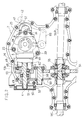
- Fig. 1 schematically shows in longitudinal section one embodiment according to the apparatus of the present invention.
- Fig. 2 is a plan view of the apparatus of Fig. 1 partly shown in section.
- Fig. 3 schematically shows an L-shaped manifold in the apparatus of Fig. 1 when viewed along the line III-III in Fig. 1.
- Fig. 4 is a sectional view taken along the line IV-IV in Fig. 3.
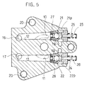
- Fig. 5 is a sectional view taken along the line V-V in Fig. 3.
- Fig. 6 is a sectional view taken along the line VI-VI in Fig. 3.
- Fig. 7 is a sectional view taken along the line VII-VII in Fig. 4.
- Fig. 8 is a sectional view taken along the line VIII-VIII in Fig. 4.
- Fig. 9-a elevation view
- Fig. 9-b plane view
- a housing 1 is of the split type and is composed of an upper shell member 1a and a lower shell member 1b.
- the housing 1 has an L-shaped block or manifold 3 fixed thereto by a bolt 20.
- a swash plate type hydraulic motor or a swash plate type piston motor M for axles 56L, 56R of motor vehicles such as motor tractors is horizontally mounted on a front end surface 3b of a vertically extending portion 302 of the manifold 3.
- a hydraulic pump P for the swash plate type piston motor M is mounted on an upper surface 3a of a horizontally extending portion 301 of the manifold 3.
- a hydraulic fluid is held in the housing 1.
- the motor M includes a cylinder block 8, a piston 46 biassed by a spring 47 toward the forward end, a fixed swash plate 53, a thrust bearing 48 and a rotary shaft 4.
- the swash plate 53 is attached to the housing 1.
- the rotary shaft 4 has a forward end protruding outside from the housing 1 at the front ends of upper and lower shell members 1a, 1b connected together.
- a brake drum 51 is mounted on the projected end of the shaft 4. Indicated at 50 is a hand brake, and at 52 a brake case.
- the shaft 4 has a gear 49 which engages a gear 59 on a counter shaft 60.
- a gear 58 on the counter shaft 60 is drivingly connected to the gear 59 and is in mesh with a ring gear 54 in a differential gear unit 55 for the axles 56L, 56R.
- a movable swash plate type hydraulic pump or a movable swash plate type piston pump can be advantageously used as the hydraulic pump P.
- This type of pump is shown as the pump P in the embodiment illustrated in the drawings.
- the illustrated movable swash plate type piston pump P includes a cylinder block 7, a piston 44 biassed by a spring 45 toward the forward end, a movable swash plate 9, a thrust bearing 9a and a rotary shaft 5.
- the rotary shaft 5 is projected at its forward end outside the upper shell member 1a of the housing 1.
- An input pulley 61 is attached to the projected forward end of the shaft 5. Power is transmitted from an engine (not shown) of a motor tractor or the like to the pulley 61.
- a first slot 10 and a second slot 11 for the pump P are formed on an upper surface of the horizontal portion 301 of the manifold 3 or on the surface 3a on which the pump P is mounted
- the first and second slots 10, 11 extend in the form of a circular arc which corresponds to a line of circular motion made by a port 71 of the cylinder block 7 being rotated.
- One of the slots 10, 11 is formed for a hydraulic fluid and the other for a return fluid.
- a first slot 14 for the motor M is formed on the front end surface of the vertical portion 302 of the manifold 3 or the surface 3b for mounting the motor on the side of upper shell member 1a, and a slot 15 for the motor M is formed on the front end surface thereof or the surface 3b for mounting the motor on the side of lower shell member 1b.
- the first and second slots 14, 15 horizontally extend in the form of a circular arc which corresponds to a line of circular motion made by a port 81 of the cylinder block 8 being rotated.
- One of the slots 14, 15 is formed for a hydraulic fluid and the other for a return fluid.
- the slots 10, 11 for the pump are in communication with the slots 15, 14 respectively for the motor M via passages in the manifold 3. More specifically, the slots 10, 11 communicate respectively with passages 12, 13 longitudinally extending within the horizontal portion 301 of the manifold 3. The slots 15, 14 communicate respectively with passages 16, 17 vertically extending within the vertical portion 302 of the manifold 3. The passages 12 and 16 cross each other for communication, and the passages 13 and 17 cross each other for communication.
- the pump P is operated to circulate the hydraulic fluid between the pump P and the motor M, whereby the motor M is rotated.
- the movable swash plate 9 of the pump P is caused to change its inclining angle by an arm 66 to alter the number of revolution of the shaft 4 for the motor M, so that the axles 56L, 56R are rotated at a varied speed.
- the swash plate 53 for the motor M has a surface 53C inclined around a perpendicular axis as shown in Fig. 2 to operate the piston 46 in the desired manner.
- the radial load during the rotation of the motor M is applied in the direction of arrow C from the right semicircular zone of the swash plate 53 to the left semicircular zone thereof as shown in Fig. 9-a (elevation view) and in the direction of arrow C from an upper position downward as depicted in Fig. 9-b (plan view).
- the radial load applied from the motor M to the housing 1 is diffused substantially uniformly throughout the upper shell member 1a and the lower shell member 1b. This factor can reduce the costs for manufacturing the transmission system of the type described hereinbefore for axles.
- the above arrangement of the first and second slots 14, 15 for the motor M enables preferred use of the lower slot 15 as a passage of a pressurized hydraulic fluid and the upper slot 14 as a passage of a return fluid in driving forward a motor tractor or the like.
- the lower slot 15 is formed at a lower position in the vertical portion of the L-shaped manifold 3 namely, viz., a position where a passage has a high rigidity due to the structure.
- the slot 15 thus arranged is suited as a passage of a pressurized hydraulic fluid in forward driving which occurs more frequently than rearward driving.
- the upper slot 14 may be used as a passage of a pressurized hydraulic fluid in rearward driving and the lower slot 15 may be used as a passage of a return fluid in rearward driving.
- first slot 14 and the second slot 15 be gradually deeper toward a side having ports (P1, P2) leading to the hydraulic pump P from the side opposed thereto as shown in Figs. 4 and 5.
- the foregoing structure of the slots 14, 15 induces smooth flow of a pressurized fluid between the pump P and the motor M, thereby preventing cavitation which leads to improved volumetric efficiency of the apparatus of the invention.
- a check valve 21 is provided in a passage 12 for communication between the slot 10 for the pump P and the slot 15 for the motor M.
- a check valve 22 is provided in a passage 13 for communication between the slot 11 for the pump P and the slot 14 for the motor M.
- the check valves 21, 22 have ports 21P, 22P which communicate with the passages 18, 19, respectively.
- the passages 18, 19 are in communication with the interior of the housing 1 by way of a filter 6.
- the hydraulic fluid may be supplied by the valve 22 (or 21), adapted to be opened automatically on leakage, in the passage 13 (or 12) of a return fluid.
- the check valves 21, 22 may be also made open by pushing the rods 23, 24 for leftward retraction in Fig. 5.
- the check valves 21, 22 are brought to an opened state, the hydraulic fluid in the passages 12, 13 is caused to flow into the interior of the housing 1 through the passages 18, 19.
- the rods 23, 24 are retracted simultaneously by a push member 40.
- the push member 40 is pushed by an arm 42 through a rotary shaft 41 attached thereto and an eccentric pin 57.
- the eccentric pin 57 extends integrally from the shaft 41 and is movably engaged in a hole 401 of the push member 40.
- the arm 42 is held by retaining means (not shown) in a position in which the rods 23, 24 are retracted.
- the axles 56L, 56R for motor tractors or the like with the transmission system of the invention mounted thereon are in a disengaged state for release from the engagement with the shaft 4 for driving.
- the motor tractor or the like can be drawn by another motor vehicle.
Landscapes
- Engineering & Computer Science (AREA)
- General Engineering & Computer Science (AREA)
- Mechanical Engineering (AREA)
- Chemical & Material Sciences (AREA)
- Combustion & Propulsion (AREA)
- Transportation (AREA)
- Motor Power Transmission Devices (AREA)
Description
- The present invention relates to a transmission system for axles of motor vehicles such as motor tractors and the like and more particularly to a transmission system for axles of motor vehicles comprising a housing of the split type composed of upper and lower shell members wherein a L-shaped block or manifold is fixed, a swash plate type hydraulic motor or a swash plate type piston motor for driving axles is horizontally mounted on a vertically extending portion of the block or manifold, a hydraulic pump for the swash plate type piston motor is vertically mounted on a horizontally extending portion thereof, and first and second slots for said motor extend in the form of a circular arc on the vertically extending portion thereof.
- A transmission system of the above type is known from US-A-4891943. The transmission system of this type comprising an assembly of a hydraulic pump, a swash plate type hydraulic motor and a manifold having the pump and motor fixed thereto is compacter and more useful than that of the type comprising a hexahedral manifold of the vertical type, a hydraulic pump fixed to the front end surface of the manifold and a swash plate type hydraulic motor fixed to the rear end surface thereof and than that of the type comprising the same manifold, and a hydraulic pump and a swash plate type hydraulic motor mounted on an upper and a lower part in one end surface of the manifold. The transmission system of the type having a motor and a pump fixed to the front and rear side surfaces of hexahedral manifold must have a plurality of slots and a plurality of passages of hydraulic fluid both for the motor, and a plurality of slots and a plurality of passages of hydraulic fluid both for the pump, all arranged in the direction of the thickness of the manifold, so that the manifold must have a sufficiently great thickness to afford the required strength, and the assembly has a significant length. The transmission system of the type having a pump and a motor vertically side by side mounted on one end surface of the manifold has a pronounced height. When an L-shaped manifold is used, a pump can be mounted on a horizontal portion of the manifold and a motor on a vertical portion thereof, in other words the pump and motor can be compactly arranged on upper and lower parts of the manifold. Since only the slots and passages of hydraulic fluid for the motor are formed on a vertical portion of the L-shaped manifold, the vertical portion thereof can be thin-walled and an assembly can be of a short length.
- However, in the conventional transmission system of the type described at the beginning of this section, two opposed arc-shaped slots for the swash plate type piston motor which are formed on a vertical portion of an L-shaped manifold extend in both a space defined by the upper shell member of the housing and a space defined by the lower shell member thereof. Such formation of the slots results in unavoidable inclination of a swash plate with respect to a perpendicular axis in order to operate the motor piston in the desired manner.
- On rotation of the swash plate type piston motor, a radial load is caused due to a thrust load resulting from the motion of the motor piston and due to the inclination of the swash plate. The radial load is induced by 360° circular motion of motor piston and is applied in a direction from a forwardly inclined semicircular zone of the swash plate (toward the forward end of the piston) to the other semicircular zone thereof.
- Thus the conventional formation of slots results in concentrated application of radial load to either the upper shell member or the lower shell member of the housing through the swash plate. The shell member to which the radial load is concentratedly applied is required to have strength sufficient to withstand the load. Therefore the production costs are increased if a shell member of great thickness or made of a material of high strength is used to meet the requirement.
- It is an object of the invention to provide a transmission system for axles of the type described at the beginning of this section which system enables substantially uniform dissipation of radial load over the upper and lower shell members of the housing, thereby leading to a decrease of costs.
- To achieve the above object of the invention, there is provided a transmission system for axles according to the invention which comprises a housing of the split type composed of upper and lower shell members wherein a L-shaped manifold is fixed, a swash plate type piston motor for driving axles is horizontally mounted on a vertically extending portion of the manifold, a hydraulic pump for the swash plate type piston motor is vertically mounted on a horizontally extending portion thereof, and first and second slots for the swash plate type piston motor extend in the form of a circular arc on the vertically extending portion thereof, the system being characterized in that the first slot for the swash plate type piston motor is horizontally formed at a position in the vertical portion of the manifold which position exists inside the upper shell member; that the second slot for the swash plate type piston motor is horizontally formed at a position in the vertical portion of the manifold which position exists inside the lower shell member; and that the surface of the swash plate for the motor is inclined around a vertical axis.
- For the reason described later, it is desirable to make the first and second slots gradually deeper toward a side having ports leading to the hydraulic pump from the side opposed to said side.
- Fig. 1 schematically shows in longitudinal section one embodiment according to the apparatus of the present invention.
- Fig. 2 is a plan view of the apparatus of Fig. 1 partly shown in section.
- Fig. 3 schematically shows an L-shaped manifold in the apparatus of Fig. 1 when viewed along the line III-III in Fig. 1.
- Fig. 4 is a sectional view taken along the line IV-IV in Fig. 3.
- Fig. 5 is a sectional view taken along the line V-V in Fig. 3.
- Fig. 6 is a sectional view taken along the line VI-VI in Fig. 3.
- Fig. 7 is a sectional view taken along the line VII-VII in Fig. 4.
- Fig. 8 is a sectional view taken along the line VIII-VIII in Fig. 4.
- Fig. 9-a (elevation view) and Fig. 9-b (plan view) schematically show the directions of application of radial load during the rotation of hydraulic motor.
- In the drawings, a
housing 1 is of the split type and is composed of anupper shell member 1a and alower shell member 1b. - The
housing 1 has an L-shaped block ormanifold 3 fixed thereto by abolt 20. - A swash plate type hydraulic motor or a swash plate type piston motor M for
axles 56L, 56R of motor vehicles such as motor tractors is horizontally mounted on afront end surface 3b of a vertically extendingportion 302 of themanifold 3. A hydraulic pump P for the swash plate type piston motor M is mounted on anupper surface 3a of a horizontally extendingportion 301 of themanifold 3. - A hydraulic fluid is held in the
housing 1. - The motor M includes a
cylinder block 8, apiston 46 biassed by aspring 47 toward the forward end, a fixedswash plate 53, a thrust bearing 48 and arotary shaft 4. Theswash plate 53 is attached to thehousing 1. Therotary shaft 4 has a forward end protruding outside from thehousing 1 at the front ends of upper andlower shell members brake drum 51 is mounted on the projected end of theshaft 4. Indicated at 50 is a hand brake, and at 52 a brake case. Theshaft 4 has agear 49 which engages agear 59 on acounter shaft 60. Agear 58 on thecounter shaft 60 is drivingly connected to thegear 59 and is in mesh with aring gear 54 in adifferential gear unit 55 for theaxles 56L, 56R. - A movable swash plate type hydraulic pump or a movable swash plate type piston pump can be advantageously used as the hydraulic pump P. This type of pump is shown as the pump P in the embodiment illustrated in the drawings. The illustrated movable swash plate type piston pump P includes a cylinder block 7, a
piston 44 biassed by aspring 45 toward the forward end, amovable swash plate 9, a thrust bearing 9a and arotary shaft 5. Therotary shaft 5 is projected at its forward end outside theupper shell member 1a of thehousing 1. Aninput pulley 61 is attached to the projected forward end of theshaft 5. Power is transmitted from an engine (not shown) of a motor tractor or the like to thepulley 61. - A
first slot 10 and asecond slot 11 for the pump P are formed on an upper surface of thehorizontal portion 301 of themanifold 3 or on thesurface 3a on which the pump P is mounted The first andsecond slots slots - A
first slot 14 for the motor M is formed on the front end surface of thevertical portion 302 of themanifold 3 or thesurface 3b for mounting the motor on the side ofupper shell member 1a, and aslot 15 for the motor M is formed on the front end surface thereof or thesurface 3b for mounting the motor on the side oflower shell member 1b. The first andsecond slots port 81 of thecylinder block 8 being rotated. One of theslots - The
slots slots manifold 3. More specifically, theslots passages horizontal portion 301 of themanifold 3. Theslots passages vertical portion 302 of themanifold 3. Thepassages passages - The pump P is operated to circulate the hydraulic fluid between the pump P and the motor M, whereby the motor M is rotated. The
movable swash plate 9 of the pump P is caused to change its inclining angle by anarm 66 to alter the number of revolution of theshaft 4 for the motor M, so that theaxles 56L, 56R are rotated at a varied speed. - The following advantages are given by the arrangement of the
first slot 14 for the motor M on thesurface 3b for mounting the motor in thevertical portion 302 of themanifold 3 on the side ofupper shell member 1a, and by the arrangement of thesecond slot 15 for the motor M on thesurface 3b for mounting the motor in thevertical portion 302 thereof on the side oflower shell member 1b. - When the
first slot 14 and thesecond slot 15 for the motor M are formed as described above, theswash plate 53 for the motor M has a surface 53C inclined around a perpendicular axis as shown in Fig. 2 to operate thepiston 46 in the desired manner. The radial load during the rotation of the motor M is applied in the direction of arrow C from the right semicircular zone of theswash plate 53 to the left semicircular zone thereof as shown in Fig. 9-a (elevation view) and in the direction of arrow C from an upper position downward as depicted in Fig. 9-b (plan view). Thus the radial load applied from the motor M to thehousing 1 is diffused substantially uniformly throughout theupper shell member 1a and thelower shell member 1b. This factor can reduce the costs for manufacturing the transmission system of the type described hereinbefore for axles. - The above arrangement of the first and
second slots lower slot 15 as a passage of a pressurized hydraulic fluid and theupper slot 14 as a passage of a return fluid in driving forward a motor tractor or the like. Thelower slot 15 is formed at a lower position in the vertical portion of the L-shapedmanifold 3 namely, viz., a position where a passage has a high rigidity due to the structure. Theslot 15 thus arranged is suited as a passage of a pressurized hydraulic fluid in forward driving which occurs more frequently than rearward driving. Theupper slot 14 may be used as a passage of a pressurized hydraulic fluid in rearward driving and thelower slot 15 may be used as a passage of a return fluid in rearward driving. These arrangements pose no trouble because rearward driving is less frequently occasioned than forward driving. In either case, a hydraulic fluid can be supplied or discharged by conventional means through theslots - It is preferable that the
first slot 14 and thesecond slot 15 be gradually deeper toward a side having ports (P1, P2) leading to the hydraulic pump P from the side opposed thereto as shown in Figs. 4 and 5. The foregoing structure of theslots - A
check valve 21 is provided in apassage 12 for communication between theslot 10 for the pump P and theslot 15 for the motor M.A check valve 22 is provided in apassage 13 for communication between theslot 11 for the pump P and theslot 14 for the motor M. Thecheck valves ports 21P, 22P which communicate with thepassages passages housing 1 by way of a filter 6. During the rotation of the motor M, the pressurized hydraulic fluid in the passage 12 (or 13) is gradually lost due to its continuous leakage from a sliding portion during rotation. The hydraulic fluid may be supplied by the valve 22 (or 21), adapted to be opened automatically on leakage, in the passage 13 (or 12) of a return fluid. Thecheck valves rods check valves passages housing 1 through thepassages rods push member 40. Thepush member 40 is pushed by anarm 42 through arotary shaft 41 attached thereto and aneccentric pin 57. Theeccentric pin 57 extends integrally from theshaft 41 and is movably engaged in ahole 401 of thepush member 40. Thearm 42 is held by retaining means (not shown) in a position in which therods check valves axles 56L, 56R for motor tractors or the like with the transmission system of the invention mounted thereon are in a disengaged state for release from the engagement with theshaft 4 for driving. In this state, the motor tractor or the like can be drawn by another motor vehicle. - When the
arm 42 is released from the foregoing state held by the retaining means, therods springs check valves springs
Claims (2)
- A transmission system for axles of a motor vehicle which comprises a housing (1) of the split type composed of upper and lower shell members (1a, 1b) wherein a L-shaped manifold (3) is fixed, a swash plate type piston motor (M) for driving axles (56L, 56R) is horizontally mounted on a vertically extending portion (302) of the manifold (3), a hydraulic pump (P) for the swash plate type piston motor (M) is vertically mounted on a horizontally extending portion (301) thereof, and first and second slots (14, 15) for the swash plate type piston motor (M) extend in the form of a circular arc on the vertically extending portion (302) thereof, the system being characterized in that the first slot (14) for the swash plate type piston motor (M) is horizontally formed at a position in the vertical portion (302) of the manifold (3) which position exists inside the upper shell member (1a); that the second slot (15) for the swash plate type piston motor (M) is horizontally formed at a position in the vertical portion (302) of the manifold (3) which position exists inside the lower shell member (1b); and that the surface of the swash plate (53) for the motor (M) is inclined around a vertical axis.
- A transmission system according to claim 1 wherein the first slot (14) and the second slot (15) are gradually deeper toward a side having ports (P1, P2) leading to the hydraulic pump (P) from the side opposed thereto.
Priority Applications (2)
| Application Number | Priority Date | Filing Date | Title |
|---|---|---|---|
| DE1991611818 DE69111818T2 (en) | 1991-12-24 | 1991-12-24 | Gear system for axles. |
| EP19910312047 EP0548428B1 (en) | 1991-12-24 | 1991-12-24 | Transmission system for axles |
Applications Claiming Priority (1)
| Application Number | Priority Date | Filing Date | Title |
|---|---|---|---|
| EP19910312047 EP0548428B1 (en) | 1991-12-24 | 1991-12-24 | Transmission system for axles |
Publications (2)
| Publication Number | Publication Date |
|---|---|
| EP0548428A1 EP0548428A1 (en) | 1993-06-30 |
| EP0548428B1 true EP0548428B1 (en) | 1995-08-02 |
Family
ID=8208520
Family Applications (1)
| Application Number | Title | Priority Date | Filing Date |
|---|---|---|---|
| EP19910312047 Expired - Lifetime EP0548428B1 (en) | 1991-12-24 | 1991-12-24 | Transmission system for axles |
Country Status (2)
| Country | Link |
|---|---|
| EP (1) | EP0548428B1 (en) |
| DE (1) | DE69111818T2 (en) |
Families Citing this family (1)
| Publication number | Priority date | Publication date | Assignee | Title |
|---|---|---|---|---|
| US5651291A (en) * | 1994-03-14 | 1997-07-29 | Lyndhurst; Richard | Crankcase forging and forming process |
Family Cites Families (3)
| Publication number | Priority date | Publication date | Assignee | Title |
|---|---|---|---|---|
| US3293848A (en) * | 1964-09-24 | 1966-12-27 | Kuze Yoshikazu | Hydrostatic power transmission |
| JPH0771895B2 (en) * | 1988-02-03 | 1995-08-02 | 株式会社神崎高級工機製作所 | Axle drive |
| GB8927920D0 (en) * | 1989-12-11 | 1990-02-14 | Unipat Ag | Variable speed transaxle |
-
1991
- 1991-12-24 DE DE1991611818 patent/DE69111818T2/en not_active Expired - Fee Related
- 1991-12-24 EP EP19910312047 patent/EP0548428B1/en not_active Expired - Lifetime
Also Published As
| Publication number | Publication date |
|---|---|
| DE69111818D1 (en) | 1995-09-07 |
| DE69111818T2 (en) | 1995-12-14 |
| EP0548428A1 (en) | 1993-06-30 |
Similar Documents
| Publication | Publication Date | Title |
|---|---|---|
| US5163293A (en) | Axle driving apparatus with variable depth crescent oil passages | |
| US4529362A (en) | Servo pump for hydraulic systems | |
| US5768892A (en) | Rider transaxle having improved hydrostatic transmission | |
| US5201692A (en) | Rider transaxle having hydrostatic transmission | |
| US5224411A (en) | Hydraulic circuit for supplying at least one hydraulic motor incorporating "disengageable" pistons | |
| US6874319B2 (en) | Hydrostatic transmission apparatus | |
| US20160003336A1 (en) | Modular hydrostatic transmission | |
| US6477838B1 (en) | Hydrostatic machines for use in transmission and transaxle product | |
| US4843818A (en) | Rotary hydrostatic machines or transmissions | |
| CA1056209A (en) | Axial piston pump | |
| US7328576B1 (en) | Zero turn transaxle | |
| DE102005060990A1 (en) | Drive and hydrostatic piston engine with recovery of braking energy | |
| GB2032586A (en) | Hydrostatic transmission device for motor vehicles | |
| EP0305548B1 (en) | Variable-capacity hydraulic motor | |
| US7127889B1 (en) | Zero turn transaxle | |
| EP0309223B1 (en) | Hydrostatic continuously variable transmission | |
| EP0548428A1 (en) | Transmission system for axles | |
| US5038634A (en) | Power transmission system | |
| US4938024A (en) | Hydrostatic continuously variable transmission | |
| US7225617B1 (en) | Bypass mechanism for a hydraulic drive apparatus | |
| GB2056385A (en) | Power steering systems | |
| DE19855899B4 (en) | axial piston | |
| US7340892B1 (en) | Charge pump | |
| US3609973A (en) | Hydraulically driven variable speed power transmission assembly | |
| US5279185A (en) | Bevel gear support with fluid bearings for radial piston hydrostatic machine |
Legal Events
| Date | Code | Title | Description |
|---|---|---|---|
| PUAI | Public reference made under article 153(3) epc to a published international application that has entered the european phase |
Free format text: ORIGINAL CODE: 0009012 |
|
| AK | Designated contracting states |
Kind code of ref document: A1 Designated state(s): DE FR GB |
|
| 17P | Request for examination filed |
Effective date: 19930910 |
|
| 17Q | First examination report despatched |
Effective date: 19941017 |
|
| GRAA | (expected) grant |
Free format text: ORIGINAL CODE: 0009210 |
|
| AK | Designated contracting states |
Kind code of ref document: B1 Designated state(s): DE FR GB |
|
| REF | Corresponds to: |
Ref document number: 69111818 Country of ref document: DE Date of ref document: 19950907 |
|
| ET | Fr: translation filed | ||
| PLBE | No opposition filed within time limit |
Free format text: ORIGINAL CODE: 0009261 |
|
| STAA | Information on the status of an ep patent application or granted ep patent |
Free format text: STATUS: NO OPPOSITION FILED WITHIN TIME LIMIT |
|
| 26N | No opposition filed | ||
| PGFP | Annual fee paid to national office [announced via postgrant information from national office to epo] |
Ref country code: GB Payment date: 20011122 Year of fee payment: 11 |
|
| PGFP | Annual fee paid to national office [announced via postgrant information from national office to epo] |
Ref country code: FR Payment date: 20011129 Year of fee payment: 11 |
|
| REG | Reference to a national code |
Ref country code: GB Ref legal event code: IF02 |
|
| PGFP | Annual fee paid to national office [announced via postgrant information from national office to epo] |
Ref country code: DE Payment date: 20020118 Year of fee payment: 11 |
|
| PG25 | Lapsed in a contracting state [announced via postgrant information from national office to epo] |
Ref country code: GB Free format text: LAPSE BECAUSE OF NON-PAYMENT OF DUE FEES Effective date: 20021224 |
|
| PG25 | Lapsed in a contracting state [announced via postgrant information from national office to epo] |
Ref country code: DE Free format text: LAPSE BECAUSE OF NON-PAYMENT OF DUE FEES Effective date: 20030701 |
|
| GBPC | Gb: european patent ceased through non-payment of renewal fee |
Effective date: 20021224 |
|
| PG25 | Lapsed in a contracting state [announced via postgrant information from national office to epo] |
Ref country code: FR Free format text: LAPSE BECAUSE OF NON-PAYMENT OF DUE FEES Effective date: 20030901 |
|
| REG | Reference to a national code |
Ref country code: FR Ref legal event code: ST |