EP0546029B1 - Offset printing machine - Google Patents
Offset printing machine Download PDFInfo
- Publication number
- EP0546029B1 EP0546029B1 EP91915651A EP91915651A EP0546029B1 EP 0546029 B1 EP0546029 B1 EP 0546029B1 EP 91915651 A EP91915651 A EP 91915651A EP 91915651 A EP91915651 A EP 91915651A EP 0546029 B1 EP0546029 B1 EP 0546029B1
- Authority
- EP
- European Patent Office
- Prior art keywords
- cylinder
- blanket cylinder
- blanket
- coupled
- shaft
- Prior art date
- Legal status (The legal status is an assumption and is not a legal conclusion. Google has not performed a legal analysis and makes no representation as to the accuracy of the status listed.)
- Expired - Lifetime
Links
- 238000007645 offset printing Methods 0.000 title claims abstract description 26
- 230000007246 mechanism Effects 0.000 claims abstract description 50
- 230000008859 change Effects 0.000 claims description 11
- 230000008878 coupling Effects 0.000 claims description 2
- 238000010168 coupling process Methods 0.000 claims description 2
- 238000005859 coupling reaction Methods 0.000 claims description 2
- 230000007812 deficiency Effects 0.000 claims description 2
- 238000004519 manufacturing process Methods 0.000 claims description 2
- 238000007639 printing Methods 0.000 description 17
- 239000013598 vector Substances 0.000 description 8
- 230000000694 effects Effects 0.000 description 4
- 238000010586 diagram Methods 0.000 description 3
- 239000002184 metal Substances 0.000 description 3
- 230000009467 reduction Effects 0.000 description 2
- 238000010276 construction Methods 0.000 description 1
- 238000006073 displacement reaction Methods 0.000 description 1
- 230000006872 improvement Effects 0.000 description 1
- 238000000034 method Methods 0.000 description 1
- 238000012856 packing Methods 0.000 description 1
- 230000002093 peripheral effect Effects 0.000 description 1
- 238000004904 shortening Methods 0.000 description 1
Images


Classifications
-
- B—PERFORMING OPERATIONS; TRANSPORTING
- B41—PRINTING; LINING MACHINES; TYPEWRITERS; STAMPS
- B41F—PRINTING MACHINES OR PRESSES
- B41F7/00—Rotary lithographic machines
- B41F7/02—Rotary lithographic machines for offset printing
- B41F7/10—Rotary lithographic machines for offset printing using one impression cylinder co-operating with several transfer cylinders for printing on sheets or webs, e.g. satellite-printing units
-
- B—PERFORMING OPERATIONS; TRANSPORTING
- B41—PRINTING; LINING MACHINES; TYPEWRITERS; STAMPS
- B41F—PRINTING MACHINES OR PRESSES
- B41F13/00—Common details of rotary presses or machines
- B41F13/08—Cylinders
- B41F13/24—Cylinder-tripping devices; Cylinder-impression adjustments
- B41F13/34—Cylinder lifting or adjusting devices
Definitions
- This invention relates to an offset printing machine.
- the present invention relates in general to an offset printing machine and in particular relates to an offset printing machine which has an accurate means of adjusting the machine to permit simultaneous coordinated control of two or more printing couples while still allowing for variances between such couples and for providing a simplified means of adjustment wherein the force vectors are of a magnitude and direction such that predetermined desired contact pressures are maintained between the blanket cylinder and the impression cylinder and the blanket cylinder and the master cylinder.
- Offset printing machines are well known in the art and include a master or plate cylinder having a plate for carrying a transferable image thereon and an impression cylinder for carrying paper to receive the image.
- a blanket cylinder is interposed between the master cylinder and the impression cylinder such that the blanket cylinder moves eccentrically about a first pivot point to make pressure contact with the master cylinder for receiving the image and subsequently moves eccentrically about a second pivot point for making pressure contact with the impression cylinder to transfer the image to the paper.
- Such a system is disclosed in U.S. Pat. No. 4,691,631.
- Two-colour offset printing machines include a single impression cylinder, two master cylinders and two blanket cylinders.
- a first blanket cylinder is caused to move eccentrically about a first axis to make contact with a first master cylinder and receive the image therefrom and then move eccentrically about a second pivot point to make contact with the impression cylinder and transfer the first colour to the paper on the impression cylinder.
- the impression cylinder then rotates to the other pair of master and blanket cylinders where the blanket cylinder moves eccentrically into contact with the second master cylinder to receive the second colour and subsequently moves eccentrically into contact with the impression cylinder to transfer the second colour to the paper.
- This system is also disclosed in U.S. Pat. No. 4,691,631.
- the mounts for eccentrically supporting the blanket cylinder are rotationally forced against a fixed but adjustable stop which is manually adjusted in the prior art to allow a desired amount of pressure at the contact points between the master and blanket cylinders and between the blanket and impression cylinders, respectively.
- Adjustment is time-consuming, but readjustment is required for wear and the like as the press is generally set up to print with a relatively fixed thickness of plates, blankets and paper stock. Adjustment, if it is required, is accomplished by varying the thickness of the packing sheets underneath the plate on the master cylinder or paper on the impression cylinder or blanket on the blanket cylinder.
- Levers comprise part of a toggle for selectively rotating a first eccentric and an eccentric shaft such that the first eccentric moves against stops which arrest its rotation thus providing exact gap clearance between the blanket cylinder and the master cylinder and thus providing an exact contact pressure.
- Levers comprise part of a toggle for selectively rotating a first eccentric and an eccentric shaft such that the first eccentric moves against stops which arrest its rotation thus providing exact gap clearance between the blanket cylinder and the master cylinder and thus providing an exact contact pressure.
- the blanket cylinder throw-off controls are designed to be very rigid and the forces which restrain the eccentrics are caused to be directed in essentially the same direction as the impression forces and to be several times as great in magnitude.
- These forces consist of the force to move the sleeve toggle that causes the first eccentric movement of the blanket cylinder and the resisting force from the stop mechanism.
- the vector sum of these two forces must be greater than and fall between the force vector of the contact between the master cylinder and blanket cylinder and between the blanket cylinder and the impression cylinder.
- US-A-4691631 discloses a cylinder setting mechanism for an offset printing machine which effects setting of a rubber blanket cylinder into peripheral contact with an impression cylinder and the plate cylinder sequentially.
- Eccentric metal parts are rotatably mounted for rotation on laterally spaced frame vertical walls for rotation about a first axis and rotatably mount an eccentric rubber blanket cylinder shaft for rotation about a second eccentric axis.
- the eccentric rubber blanket cylinder shaft rotatably mounts the rubber blanket cylinder eccentrically about a third axis eccentric to the axis of rotation of the shaft.
- a plate cylinder setting cam and an impression cylinder setting cam are fixedly secured to the impression cylinder rotate therewith and are angularly offset.
- a plate cylinder setting mechanism includes a first toggle mechanism coupled to the eccentric metal part and a plate cylinder setting mechanism striking bar operatively positioned with respect to the plate cylinder setting cam and coupled to the first toggle mechanism cause the rubber blanket cylinder to be brought into and out of engagement with the plate cylinder.
- An impression cylinder setting mechanism includes a second toggle mechanism coupled to the eccentric rubber blanket cylinder shaft and an impression cylinder setting mechanism striking bar operatively positioned with respect to the impression cylinder setting cam and responsive thereto is coupled to the second toggle mechanism.
- US-A-4676158 discloses a plate pressure and printing pressure adjusting mechanism for permitting separate adjustment of the pressure exerted by a rubber blanket cylinder against a plate cylinder and the same rubber blanket cylinder against an impression cylinder.
- First and second toggle mechanisms are mounted for reciprocation to opposite sides of the axis of rotation of the rubber blanket cylinder and in similar directions to bring the rubber blanket cylinder into and out of engagement with the plate cylinder and impression cylinder, respectively.
- a first arm fixedly mounted on the eccentric shaft supporting the rubber blanket cylinder is connected through the first toggle mechanism to a first adjusting arm pivotably supported on the frame, and supports an axial adjusting screw and being spring biased so as to cause the end of the adjusting screw to bear on a first radial cam whose periphery may be shifted.
- a second arm is pivotably supported on the frame with one portion coupled through a link to the eccentric metal part supporting the rubber blanket cylinder.
- the second toggle mechamism links the other portion of the second arm to a second adjusting arm pivotably supported on the frame and carrying a threaded adjustment screw whose threaded end bears on a second rotatably adjustable radial cam and maintained thereagainst by biasing means acting on the second adjusting arm.
- an offset printing machine comprising: laterally spaced vertical frame walls; a fixed master cylinder rotatably mounted between said walls for carrying a transferable image thereon; a fixed impression cylinder rotatably mounted between said walls for carrying paper thereon for receiving said image; a blanket cylinder rotatably mounted between said walls for movement about a first axis to make pressure contact with the master cylinder for receiving the image and for subsequent movement about a second axis for making pressure contact with the impression cylinder to transfer the image to the paper; characterised in that the offset printing machine further includes: means coupled to said blanket cylinder for independently and selectively adjusting the first and second axes so as to maintain a first predetermined desired contact pressure between the blanket cylinder and the master cylinder and to maintain a second predetermined contact pressure between the blanket cylinder and the impression cylinder; a stop mechanism associated with said first axis and positioned to allow said blanket cylinder to move toward said master cylinder only a predetermined amount so as to maintain said first predetermined contact pressure; and means coupled
- a sleeve actuator is mounted in the frame side walls of the printing mechanism to cause the blanket cylinder to move eccentrically into and out of pressure contact with the master cylinder.
- a stub shaft is eccentrically mounted in the sleeve and rotatably holds the blanket cylinder. The stub shaft is rotated to cause the blanket cylinder to move eccentrically into and out of pressure contact with the impression cylinder.
- Pneumatic cylinders are connected to levers which comprise part of a toggle for selectively rotating the sleeve actuator and the eccentric stub shaft. The sleeve moves against stops which arrest its rotation, thus providing an exact gap between the blanket cylinder and the master cylinder and causing an exact impression pressure.
- the toggle lever for moving the sleeve and thus the blanket cylinder into and out of pressure contact with the master cylinder is mounted on an eccentric bushing.
- the eccentric bushing is rotatably adjustable to change the pivot point of the toggle lever, which changes the amount of movement of the sleeve actuator and thus the amount of movement of the blanket cylinder toward and away from the master cylinder. In this manner, the contact pressure is adjusted as desired in a simple and efficient manner.
- pivot point of the second toggle lever which rotates the eccentric stub shaft is also adjustable so that the amount of rotation of the stub shaft can be changed, thus changing the amount of movement of the blanket cylinder towards and away from the impression cylinder to maintain a constant or predetermined contact pressure.
- the stop for the sleeve actuator is mounted on the sleeve itself and a cam is mounted on the shaft for rotatably adjusting the eccentric bushing.
- An arm is pivotally mounted for connection between the cam and the stop so that when the pivot point of the toggle lever moving the sleeve is adjusted by rotating the eccentric bushing, the cam is also adjusted so that the contact of the stop with the arm is simultaneously adjusted.
- adjustment of the toggle link is automatically coordinated with an adjustment of the stop.
- the throw-off toggle levers are designed to be very rigid and cause the forces which restrain the eccentrics to be directed in essentially the same direction as the impression forces and several times as great in magnitude. Therefore, any tendency for the blanket cylinder to bounce against either the master cylinder or the impression cylinder is minimized, thus minimizing streaking and slurring of the printed image.
- the first adjustment arms for each of the toggle levers that move the sleeve actuators are coupled by a first rod to each other.
- the rod is threadedly attached at each end to the first adjustment arms and has a wheel rotatably attached to the rod for rotating the rod.
- rotation of the rod in a first direction moves the first adjustment arms of each of the sleeve actuators in opposite directions to simultaneously adjust the pivot points of the toggle levers of each of the sleeves, thus simultaneously adjusting the contact pressure between each of the blanket cylinders and its corresponding master cylinder.
- a digital counter is coupled to the rod such that rotation of the rod in either direction causes the counter to change its count to provide an indication of the movement of each of the first adjustment arms by rotation of the rod.
- a second rod is coupled to each of the second adjustment arms for the eccentric stub shafts such that rotation of the rod in either direction causes the second adjustment arms to move simultaneously to change the rotation of the eccentric stub shafts and thereby change the movement of the blanket cylinder toward and away from the impression cylinder to maintain a substantially constant contact pressure.
- a digital counter is coupled to the second rod to digitally indicate the amount of movement of the second adjustment arms and thus indicate the change in contact pressure between each blanket cylinder and the impression cylinder.
- a two-colour offset press or printing machine 10 is illustrated in FIG. 1.
- Paper sheets from paper stack 22 are picked up in any well-known manner such as by sucker tubes (not shown) and are conveyed to a paper feed conveyor 24 to a transfer cylinder 26.
- a system for transferring one ink to apply a first colour image to the sheet includes an offset blanket cylinder 16 and master cylinder 14, and another system for transferring another ink to apply a second colour image to the sheet includes a second blanket cylinder 20 and master cylinder 18.
- the system requires that the image transmitting surfaces on the blanket cylinders 16 and 20 be suitably inked in order to print an acceptable image on the initial sheet of paper on the impression cylinder 12 as it passes through the machine. Accordingly, before the blanket cylinders 16 and 20 contact the sheet of paper on the impression cylinder 12, it is desirable that each be inked. Thus, the surfaces of the blanket cylinders 16 and 20 are brought into contact with the surfaces of the respective master cylinders 14 and 18, respectively, while being separated from the surface of the impression cylinder 12. Once the surfaces of the blanket cylinders 16 and 20 are inked, they are brought into contact successively with the sheet of paper on the impression cylinder 12. The sheet of paper then passes through delivery cylinder 28 along paper path 30 to the receiving stack 32.
- each master cylinder 14 and 18 has a cylinder gap to carry a clamp for mounting the plate. Because the gap mechanism is well known in the art, it is not shown here.
- each of the blanket cylinders 16 and 20 also has a gap mechanism for carrying a clamp to hold the blanket on the cylinder. This gap mechanism is not shown because it is also well known in the art.
- Each of these gap mechanisms is always lower than the surface of the cylinder itself. Thus, each time the gap encounters an adjacent cylinder, no force is applied between the cylinders.
- On the impression cylinder 12 there are two gap mechanisms because it is a double-sided cylinder and the grippers are located in the gaps. These gaps are not shown in the drawings because they are also well known in the art.
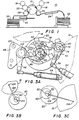
- FIG. 2 is a diagrammatic representation of the mechanism necessary to bring the blanket cylinders 16 and 20 into and out of correspondence with their respective master cylinder 14 and 18 and the impression cylinder 12.
- first toggle lever 36 moves first toggle lever 36 to the position shown, it causes linkage 38 to move sleeve 40 in a counterclockwise rotational direction about a first pivot point 42 (shown in FIG. 3A) thus causing the blanket cylinder 20 to move into contact with master cylinder 18 so that blanket cylinder 20 may be inked.
- the counterclockwise rotational movement of toggle lever 36 and sleeve 40 Continues until it is stopped by engagement of stop member 37 with linkage 38. Stop member 37 is threadably interconnected with lever 36 and moves therewith until it contacts linkage 38. After stop 37 engages linkage 38, further movement of both sleeve 40 and lever 36 is arrested thus providing a positive stop element therefor.
- second air cylinder 44 moves second toggle lever 46 clockwise to cause linkage 48 to rotate eccentric shaft stub 50 clockwise about its centerline 52.
- This clockwise movement of toggle lever 46 and shaft stub 50 continues until it is stopped by engagement of stop member 53 with linkage 48.
- Stop member 53 is threadably interconnected with lever 46 and moves therewith until it contacts linkage 48. After stop 53 engages linkage 48, further movement of both shaft 50 and lever 46 is arrested thus providing a positive stop element therefor.
- air cylinder 54 moves toggle lever 56 to rotate sleeve 58 through linkage 60 to move the blanket cylinder 16 into contact with the master cylinder 14 and stop member 61 acts to stop such rotary movement of toggle lever 56 and sleeve 58.
- air cylinder 62 moves toggle lever 64 counterclockwise to cause linkage 66 to rotate eccentric shaft stub 68 about centerline 70 causing the blanket cylinder 16 to move into contact with the impression cylinder 12.
- Counterclockwise movement of lever 64 and shaft stub 68 continues until it is stopped by engagement of stop member 69 with linkage 66.
- Stop member 69 is threadably interconnected with lever 64 and moves therewith until it contacts linkage 66. After stop 69 engages linkage 66, further movement of both shaft stub 68 and lever 64 is arrested thus providing a positive stop element therefor.
- a predetermined amount of contact pressure is desired between the blanket cylinders 16 and 20 and the respective master cylinders 14 and 18 and between the blanket cylinders 16 and 20 and the impression cylinder 12. Adjustment, however, must be made for normal wear, thickness of plates, thickness of blankets, and paper stock used.
- a first mechanism is utilized to adjust the amount of eccentric movement of each of the blanket cylinders 16 and 20 about a first pivot point toward or away from the respective master cylinders 14 and 18. Since they are identical, only one of the mechanisms will be described in detail.
- a first adjustment arm 72 is rigidly attached to a sleeve adjustment shaft 74. Mounted on that same shaft 74 is an eccentric bushing 76 on which the first toggle lever 36 is pivotally mounted.
- a master/blanket cylinder adjustment rod 78 is coupled by threads 80 to a plate 82 that is pivotally attached to the first adjustment arm 72.
- the rod 78 is mounted to the machine 10 by threaded sleeve 83. Rotation of sleeve 83 causes axial displacement of rod 78 whereby adjustment arms 72 and 96 are complementarily biased into adjustment. Furthermore, by rotating knurled wheel 84, rigidly attached to rod 78, the rod 78 is rotated causing the threads 80 to move the plate 82 towards or away from the knurled wheel 84, thereby moving the first adjustment arm 72.
- a digital counter 86 is coupled through gears 88 to the rod 78 to give a digital indication in windows 90 of the amount of rotation of rod 78 and thus giving an indication of the amount of movement of blanket cylinder 20 towards or away from the master cylinder 18.
- the rod 78 is coupled to the other side of the machine 10 to plate 92 through threads 94 to move second adjustment arm 96 in a like manner as described previously with respect to first adjustment arm 72.
- the threads 80 and 94 are reverse threads; thus, for instance, the threads 80 may be right-handed threads while the threads 94 may be left-handed threads.
- triangular plate 98 is pivotally attached to the machine 10 at pivot point 100.
- the second toggle lever 46 is pivotally attached to the triangular plate 98 by a bolt at pivot point 102.
- the pivot point 102 of second toggle lever 46 is also moved which changes the amount of rotation of eccentric stub shaft 50 when the toggle lever 46 is rotated.
- a second rod 104 is attached to the machine 10 by brackets 106.
- a second knurled wheel 112 is rigidly attached to rod 104 for enabling the rod 104 to be rotated.
- the threads 108 cause plate 110 to move towards or away from the knurled wheel 112, thus moving triangular plate 98 about pivot point 100 and thereby changing the pivot point 102 of the second toggle lever 106 to adjust the amount of movement of the blanket cylinder 20 towards or away from the impression cylinder 12.
- a digital counter 114 is coupled to the shaft 104 through gear train 116 to give a digital indication of the amount of movement of the blanket cylinder 20 towards or away from the impression cylinder 12.
- the second rod 104 is also coupled to the other side of the two-color offset machine to simultaneously adjust the other blanket cylinder 16 with respect to the impression cylinder 12.
- the other end of rod 104 has threads 118 coupled to plate 120 to adjust the movement of triangular plate 122 and thereby adjust the movement of the second blanket cylinder 16 towards arid away from impression cylinder 12.
- the contact pressure between the blanket cylinders 16 and 20 and their corresponding master cylinders 14 and 18 can be adjusted simultaneously while the contact pressure between the blanket cylinders 16 and 20 and the impression cylinder 12 may be adjusted simultaneously.
- FIG. 3A is a detailed diagram of the mechanism for adjusting blanket cylinder 20 with respect to master cylinder 18 and impression cylinder 12.
- the blanket cylinder 20 rotates about axis 124.
- the sleeve actuator 40 rotates about centerline 42.
- the eccentrically mounted shaft stub 50 rotates about centerline 52.
- each of the axes 42, 52 and 124 is eccentric with respect to the other.
- FIG. 3B if the sleeve 40 is rotated counterclockwise, the line 128 connecting the rotational axis 124 of blanket cylinder 20 and the rotational axis 126 of master cylinder 18 becomes shorter.
- the blanket cylinder 20 is moved eccentrically towards the master cylinder 18.
- eccentric shaft stub 50 when rotated clockwise, it tends to move the centerline 124 of blanket cylinder 20 in a clockwise direction, thus lengthening line 132 connecting the centerline 124 of blanket cylinder 20 and the centerline 134 of impression cylinder 12, thus eccentrically moving the blanket cylinder 20 away from the impression cylinder 12.
- the pivot point 102 of toggle lever 46 when triangular plate 98 is moved counterclockwise about pivot point 100, the pivot point 102 of toggle lever 46 is moved counterclockwise, thus tending to rotate eccentric shaft stub 50 counterclockwise and eccentrically move blanket cylinder 20 toward impression cylinder 12.
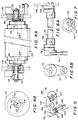
- FIG. 4A is a diagrammatic representation of the blanket cylinder 20 and its relationship to the eccentric shaft stub 50 and the sleeve actuator 40.
- the sleeves 40 are mounted in vertical side walls 136 and 138 for rotation about axis 42 therein.
- An eccentric stub shaft 50 is mounted eccentrically for rotation about centerline 52 in each of the sleeves 40.
- the eccentric stub shaft 50 enables the blanket cylinder 20 to be eccentrically mounted therein about axis 124.
- FIG. 4B rotation of the sleeves 40 about their centerline 42 eccentrically moves the blanket cylinder 20 and its centerline 124 about centerline 42.
- each blanket cylinder can be adjusted with respect to its associated master cylinder to compensate for wear, thickness of plates and thickness of blankets.
- the mechanism shown in FIGS. 4A and 4B can also adjust blanket cylinder 20 with respect to impression cylinder 12 to compensate for wear, paper stock used and thickness of blankets.
- a mount 142 is integrally formed with the sleeve 40.
- a bolt 146 having a head 147 is inserted in an orifice 144 in mount 142.
- Springs 148 such as well-known Belleville washers, are inserted on the bolt between the bolt head 147 and the mount 142.
- a cam 150 is mounted on sleeve adjustment shaft 74 where the eccentric bushing 76 is mounted.
- An arm 152 pivoting about shaft 154 couples the cam 150 and the bolt head 147.
- toggle arm 36 shown in FIG. 3A
- the mount 144 is also moved counterclockwise bringing the bolt head 147 into contact with the end 156 of arm 152, thus stopping rotation of the sleeve 40.
- End 156 of arm 152 bears on the bolt head 147, thus causing it to compress the springs or Belleville washers 148.
- the purpose of the springs or Belleville washers 148 is to maintain a constant force, thus compensating for manufacturing tolerances and deficiencies. If, however, the adjustment arm 72 in FIG.
- FIG. 6A is an end view from the left end illustrating the pivot point 73 to which the adjustment rod 78, threadedly coupled by threads 80 to plate 82, moves adjustment arm 72 to rotate shaft 74.
- FIG. 7 is an end view from the right end of FIG. 6A illustrating the bearing 150 mounted in vertical side wall 138 and again illustrating the relationship of cam 150, eccentric bushing 76 and shaft 74.
- FIG. 8 is a diagram of one of the blanket cylinder throw-off mechanisms illustrating the various forces that are applied to the sleeve actuator and the eccentric shaft stub during the printing mode.
- the forces applied at the centerline 42 of the sleeve 40 are F t (1), the force applied for sleeve rotation; F L (1), the sleeve toggle arm lock-up force; and F s , the sleeve stop force caused by the stop mechanism.
- the forces about the centerline 52 of the eccentric shaft stub 50 are F L (2), and the shaft toggle lock-up force, F t (2), the force applied during rotation of the eccentric stub shaft 50.
- the forces occurring about the axis of rotation 124 of the blanket cylinder 20 are P 1 , the cylinder pressure loading between the master cylinder 18 and the blanket cylinder 20 for a duration of 60° during the gap event between the impression cylinder 12 and the blanket cylinder 20, the force P 2 , the cylinder pressure loading between the impression cylinder 12 and the blanket cylinder 20 for a duration of 60° during the gap event between the master cylinder 18 and the blanket cylinder 20, and P 3 , the resultant of the forces P 1 and P 2 for a duration of 240° when no gap event occurs.
- the force W bl the blanket cylinder weight, is also located at axis 124.
- the pressure load vector between the cylinders swings from P 1 to P 2 or an angle of 135° during operation.
- the resultant force swing from all of the forces applied from the sleeve 40/eccentric shaft stub 50 to the frame side walls of the machine 10 reduces significantly due to two factors: (1) the toggle lock-up forces F L (1) and F L (2) and (2) the sleeve stop force F s .
- FIG. 9 the cylinder pressure loading conditions P 1 , P 2 and P 3 are shown at the center of the sleeve 40 to demonstrate the resulting forces R 1 , R 2 and R 3 that are applied from the sleeve/eccentric shaft stub assembly to the frame for loading conditions P 1 , P 2 and P 3 , respectively. It can be seen that there is a significant reduction of force vector swing angle between R 1 and R 2 during the printing mode as a result of the sleeve stop and the toggle lock-up design.
- an improved cylinder setting mechanism for either a single or two-color offset press that moves the blanket cylinder into and out of pressure contact with the master cylinder about a first pivot point and subsequently for eccentrically moving the blanket cylinder into and out of pressure contact with the impression cylinder about a second pivot point so that the blanket cylinder can be inked prior to transferring the image to the paper on the impression cylinder.
- the improvement comprises a simplified control to provide independent adjustment of each of the first and second pivot points to compensate for wear, varying thickness of plates, blankets and paper stock.
- the invention comprises a toggle which sets the pressure between the blanket cylinder and the master cylinder to operate against a stop to ensure that there is a predetermined contact pressure between the surfaces of the blanket cylinder and the master cylinder and to automatically adjust the stop commensurate with an adjustment of the toggle for a different thickness blanket so that the desired offset printing pressure between the master and the blanket cylinder surfaces is held at the optimum level.
Landscapes
- Engineering & Computer Science (AREA)
- Mechanical Engineering (AREA)
- Rotary Presses (AREA)
- Application Of Or Painting With Fluid Materials (AREA)
- Impact Printers (AREA)
- Soil Working Implements (AREA)
Abstract
Description
- This invention relates to an offset printing machine. The present invention relates in general to an offset printing machine and in particular relates to an offset printing machine which has an accurate means of adjusting the machine to permit simultaneous coordinated control of two or more printing couples while still allowing for variances between such couples and for providing a simplified means of adjustment wherein the force vectors are of a magnitude and direction such that predetermined desired contact pressures are maintained between the blanket cylinder and the impression cylinder and the blanket cylinder and the master cylinder.
- Offset printing machines are well known in the art and include a master or plate cylinder having a plate for carrying a transferable image thereon and an impression cylinder for carrying paper to receive the image. A blanket cylinder is interposed between the master cylinder and the impression cylinder such that the blanket cylinder moves eccentrically about a first pivot point to make pressure contact with the master cylinder for receiving the image and subsequently moves eccentrically about a second pivot point for making pressure contact with the impression cylinder to transfer the image to the paper. Such a system is disclosed in U.S. Pat. No. 4,691,631.
- Two-colour offset printing machines are also known and they include a single impression cylinder, two master cylinders and two blanket cylinders. A first blanket cylinder is caused to move eccentrically about a first axis to make contact with a first master cylinder and receive the image therefrom and then move eccentrically about a second pivot point to make contact with the impression cylinder and transfer the first colour to the paper on the impression cylinder. The impression cylinder then rotates to the other pair of master and blanket cylinders where the blanket cylinder moves eccentrically into contact with the second master cylinder to receive the second colour and subsequently moves eccentrically into contact with the impression cylinder to transfer the second colour to the paper. This system is also disclosed in U.S. Pat. No. 4,691,631.
- In both single and multi-color such as two color offset printing machines, a predetermined contact pressure must be maintained between the blanket cylinder and the master cylinder and between the blanket cylinder and the impression cylinder. Thus, the mounts for eccentrically supporting the blanket cylinder are rotationally forced against a fixed but adjustable stop which is manually adjusted in the prior art to allow a desired amount of pressure at the contact points between the master and blanket cylinders and between the blanket and impression cylinders, respectively. Adjustment is time-consuming, but readjustment is required for wear and the like as the press is generally set up to print with a relatively fixed thickness of plates, blankets and paper stock. Adjustment, if it is required, is accomplished by varying the thickness of the packing sheets underneath the plate on the master cylinder or paper on the impression cylinder or blanket on the blanket cylinder.
- Small sheet-fed presses, in particular, are required to accommodate a wide range of plate and paper stock thicknesses, so such semi-permanent adjustments mentioned above are unusable. If the settings are to be made frequently, then they must be done simply and quickly which is difficult as the adjustment of the actuating means requires that the stop must also be accurately readjusted. Because it is necessary for the eccentrics to rotate freely thereby necessitating some clearance or springiness as in the case of bearings, if rigid stops, such as used in adjusting a web-type press, are not used to rotationally position the eccentrics, there will be a looseness which will allow the printing cylinders to bounce slightly which will be visible in the printing. Wear will obviously increase the looseness. This bouncing of the cylinders is caused by the manner in which they operate. Levers comprise part of a toggle for selectively rotating a first eccentric and an eccentric shaft such that the first eccentric moves against stops which arrest its rotation thus providing exact gap clearance between the blanket cylinder and the master cylinder and thus providing an exact contact pressure. For a significant portion of the revolution of the blanket cylinder and the master cylinder, there is no impression or contact pressure during which time the cylinders tend to move together as there is no resisting force. When the cylinders rotate around to where the printing begins again, an impact occurs which tends to push the cylinders apart. They are eventually restored to their former positions after several reverberations. This ringing of the printing cylinders occurs and is disruptive of proper printing. Additionally, when this occurs between, for instance, the master cylinder and the blanket cylinder, the effect will be felt at the image transfer point between the blanket cylinder and the impression cylinder. It is an effect commonly referred to as streaking.
- Although it is not possible to totally eliminate this effect, it may be minimized to an acceptable level if the blanket cylinder throw-off controls are designed to be very rigid and the forces which restrain the eccentrics are caused to be directed in essentially the same direction as the impression forces and to be several times as great in magnitude. These forces consist of the force to move the sleeve toggle that causes the first eccentric movement of the blanket cylinder and the resisting force from the stop mechanism. The vector sum of these two forces must be greater than and fall between the force vector of the contact between the master cylinder and blanket cylinder and between the blanket cylinder and the impression cylinder. In such case, even though a certain amount of looseness is required to allow for the eccentrics be free to turn, the eccentrics are pressed against their mounts in essentially the same direction as the impression pressures and any tendency for the eccentrics to move within their mounts is virtually eliminated. Thus, it is seen that the adjustment of the eccentric actuating means and the adjustment of the stop require a balancing of forces. If the stop force is too great, the toggle lever cannot be locked and, if it is too little, the eccentric actuating means will be loose and there will be streaking and slurring of the printed image. On presses where impression pressure adjustments are seldom made, as in the web-type press, this manual adjustment can readily be accommodated. However, on presses requiring frequent changes in paper and plate thickness, protracted adjustment procedures are undesirable.
- US-A-4691631 discloses a cylinder setting mechanism for an offset printing machine which effects setting of a rubber blanket cylinder into peripheral contact with an impression cylinder and the plate cylinder sequentially. Eccentric metal parts are rotatably mounted for rotation on laterally spaced frame vertical walls for rotation about a first axis and rotatably mount an eccentric rubber blanket cylinder shaft for rotation about a second eccentric axis. The eccentric rubber blanket cylinder shaft rotatably mounts the rubber blanket cylinder eccentrically about a third axis eccentric to the axis of rotation of the shaft. A plate cylinder setting cam and an impression cylinder setting cam are fixedly secured to the impression cylinder rotate therewith and are angularly offset. A plate cylinder setting mechanism includes a first toggle mechanism coupled to the eccentric metal part and a plate cylinder setting mechanism striking bar operatively positioned with respect to the plate cylinder setting cam and coupled to the first toggle mechanism cause the rubber blanket cylinder to be brought into and out of engagement with the plate cylinder. An impression cylinder setting mechanism includes a second toggle mechanism coupled to the eccentric rubber blanket cylinder shaft and an impression cylinder setting mechanism striking bar operatively positioned with respect to the impression cylinder setting cam and responsive thereto is coupled to the second toggle mechanism.
- US-A-4676158 discloses a plate pressure and printing pressure adjusting mechanism for permitting separate adjustment of the pressure exerted by a rubber blanket cylinder against a plate cylinder and the same rubber blanket cylinder against an impression cylinder. First and second toggle mechanisms are mounted for reciprocation to opposite sides of the axis of rotation of the rubber blanket cylinder and in similar directions to bring the rubber blanket cylinder into and out of engagement with the plate cylinder and impression cylinder, respectively. A first arm fixedly mounted on the eccentric shaft supporting the rubber blanket cylinder is connected through the first toggle mechanism to a first adjusting arm pivotably supported on the frame, and supports an axial adjusting screw and being spring biased so as to cause the end of the adjusting screw to bear on a first radial cam whose periphery may be shifted. A second arm is pivotably supported on the frame with one portion coupled through a link to the eccentric metal part supporting the rubber blanket cylinder. The second toggle mechamism links the other portion of the second arm to a second adjusting arm pivotably supported on the frame and carrying a threaded adjustment screw whose threaded end bears on a second rotatably adjustable radial cam and maintained thereagainst by biasing means acting on the second adjusting arm. By rotating the adjusting cams, the first and second toggle mechamisms are individually adjusted to seperately vary the plate pressure and printing pressure.
- According to the invention there is provided an offset printing machine comprising: laterally spaced vertical frame walls; a fixed master cylinder rotatably mounted between said walls for carrying a transferable image thereon; a fixed impression cylinder rotatably mounted between said walls for carrying paper thereon for receiving said image; a blanket cylinder rotatably mounted between said walls for movement about a first axis to make pressure contact with the master cylinder for receiving the image and for subsequent movement about a second axis for making pressure contact with the impression cylinder to transfer the image to the paper; characterised in that the offset printing machine further includes: means coupled to said blanket cylinder for independently and selectively adjusting the first and second axes so as to maintain a first predetermined desired contact pressure between the blanket cylinder and the master cylinder and to maintain a second predetermined contact pressure between the blanket cylinder and the impression cylinder; a stop mechanism associated with said first axis and positioned to allow said blanket cylinder to move toward said master cylinder only a predetermined amount so as to maintain said first predetermined contact pressure; and means coupled to said stop mechanism and said independent and selective adjusting means to change the position of said stop mechanism when the first axis is adjusted so as to maintain the first predetermined contact pressure between the blanket cylinder and the master cylinder.
- In the offset printing machine embodying the present invention, a sleeve actuator is mounted in the frame side walls of the printing mechanism to cause the blanket cylinder to move eccentrically into and out of pressure contact with the master cylinder. A stub shaft is eccentrically mounted in the sleeve and rotatably holds the blanket cylinder. The stub shaft is rotated to cause the blanket cylinder to move eccentrically into and out of pressure contact with the impression cylinder. Pneumatic cylinders are connected to levers which comprise part of a toggle for selectively rotating the sleeve actuator and the eccentric stub shaft. The sleeve moves against stops which arrest its rotation, thus providing an exact gap between the blanket cylinder and the master cylinder and causing an exact impression pressure. The toggle lever for moving the sleeve and thus the blanket cylinder into and out of pressure contact with the master cylinder is mounted on an eccentric bushing. The eccentric bushing is rotatably adjustable to change the pivot point of the toggle lever, which changes the amount of movement of the sleeve actuator and thus the amount of movement of the blanket cylinder toward and away from the master cylinder. In this manner, the contact pressure is adjusted as desired in a simple and efficient manner.
- In addition, the pivot point of the second toggle lever which rotates the eccentric stub shaft is also adjustable so that the amount of rotation of the stub shaft can be changed, thus changing the amount of movement of the blanket cylinder towards and away from the impression cylinder to maintain a constant or predetermined contact pressure.
- In addition, the stop for the sleeve actuator is mounted on the sleeve itself and a cam is mounted on the shaft for rotatably adjusting the eccentric bushing. An arm is pivotally mounted for connection between the cam and the stop so that when the pivot point of the toggle lever moving the sleeve is adjusted by rotating the eccentric bushing, the cam is also adjusted so that the contact of the stop with the arm is simultaneously adjusted. Thus, adjustment of the toggle link is automatically coordinated with an adjustment of the stop. The throw-off toggle levers are designed to be very rigid and cause the forces which restrain the eccentrics to be directed in essentially the same direction as the impression forces and several times as great in magnitude. Therefore, any tendency for the blanket cylinder to bounce against either the master cylinder or the impression cylinder is minimized, thus minimizing streaking and slurring of the printed image.
- In the embodiment of the present invention, when a two-colour offset printing machine is utilized, the first adjustment arms for each of the toggle levers that move the sleeve actuators are coupled by a first rod to each other. The rod is threadedly attached at each end to the first adjustment arms and has a wheel rotatably attached to the rod for rotating the rod. Thus, rotation of the rod in a first direction moves the first adjustment arms of each of the sleeve actuators in opposite directions to simultaneously adjust the pivot points of the toggle levers of each of the sleeves, thus simultaneously adjusting the contact pressure between each of the blanket cylinders and its corresponding master cylinder. A digital counter is coupled to the rod such that rotation of the rod in either direction causes the counter to change its count to provide an indication of the movement of each of the first adjustment arms by rotation of the rod.
- A second rod is coupled to each of the second adjustment arms for the eccentric stub shafts such that rotation of the rod in either direction causes the second adjustment arms to move simultaneously to change the rotation of the eccentric stub shafts and thereby change the movement of the blanket cylinder toward and away from the impression cylinder to maintain a substantially constant contact pressure. Again, a digital counter is coupled to the second rod to digitally indicate the amount of movement of the second adjustment arms and thus indicate the change in contact pressure between each blanket cylinder and the impression cylinder.
- The invention will now be further described by way of example with reference to the accompanying drawings in which:
- FIG. 1 is general diagrammatic representation of an offset printing machine including a common impression cylinder, two master cylinders and two blanket cylinders;
- FIG. 2 is a general diagrammatic representation of the novel printing machine of the present invention illustrating the blanket cylinder/master cylinder adjustment mechanism and the blanket cylinder/impression cylinder adjustment mechanism;
- FIG. 3A is a detailed drawing of the adjustment mechanism for both the first pivot point for the blanket cylinder/master cylinder adjustment and the second pivot point for the blanket cylinder/impression cylinder adjustment;
- FIG. 3B is an illustration of the manner in which adjustment of the sleeve actuator adjusts the eccentric movement of the blanket cylinder toward and away from the master cylinder;
- FIG. 3C diagrammatically illustrates the manner in which adjustment of the eccentric stub shaft adjusts movement of the blanket cylinder toward and away from the impression cylinder;
- FIG. 4A is a diagrammatic representation of the blanket cylinder eccentrically mounted on the stub shaft which is eccentrically mounted on the sleeve actuators which are mounted in the vertical frame walls of the machine;
- FIG. 4B is a diagrammatic representation of the end view of the device in FIG. 4A illustrating the relationship of the axis of the sleeve actuator, the axis of the eccentric stub shaft, and the axis of the blanket cylinder;
- FIG. 5 illustrates the adjustable stop mechanism whereby adjustment of the pivot point of the sleeve actuator also adjusts the stop mechanism simultaneously;
- FIG. 6A is a side view of the shaft which adjusts the pivot point of the toggle lever that moves the sleeve actuator and simultaneously adjusts the stop mechanism;
- FIG. 6B is an end view of the shaft of FIG. 6A from the left side thereof;
- FIG. 7 is a end view of FIG. 6A from the right side thereof;
- FIG. 8 is a schematic representation of the mechanism for adjusting the first and second pivot points of the blanket cylinder illustrating the forces that are applied about the axis for the sleeve actuator, the axis for the eccentric stub shaft, and the axis for the blanket cylinder; and
- FIG. 9 illustrates the resultant forces at the center of the sleeve actuator to demonstrate the significant reduction of resultant force vector swing and increase of the resultant force vector magnitude during the printing mode as a result of the contact forces between the blanket cylinder and the master cylinder and the blanket cylinder and the impression cylinder.
- While the following description is set forth in relation to a two-colour printing machine for ease of description, the invention is not so limited and the technical concept of the invention may be applied to conventional single-colour printing machines as well as multi-colour printing machines.
- A two-colour offset press or printing
machine 10 is illustrated in FIG. 1. Paper sheets frompaper stack 22 are picked up in any well-known manner such as by sucker tubes (not shown) and are conveyed to apaper feed conveyor 24 to atransfer cylinder 26. The paper stops and registers and then thetransfer cylinder 26 grips the paper and transfers it to theimpression cylinder 12 that also has grippers 11 thereon to pick up the sheets. A system for transferring one ink to apply a first colour image to the sheet includes an offsetblanket cylinder 16 andmaster cylinder 14, and another system for transferring another ink to apply a second colour image to the sheet includes asecond blanket cylinder 20 andmaster cylinder 18. - At the beginning of the operation of the
machine 10, the system requires that the image transmitting surfaces on theblanket cylinders impression cylinder 12 as it passes through the machine. Accordingly, before theblanket cylinders impression cylinder 12, it is desirable that each be inked. Thus, the surfaces of theblanket cylinders respective master cylinders impression cylinder 12. Once the surfaces of theblanket cylinders impression cylinder 12. The sheet of paper then passes throughdelivery cylinder 28 alongpaper path 30 to the receivingstack 32. It is well known that eachmaster cylinder blanket cylinders impression cylinder 12, there are two gap mechanisms because it is a double-sided cylinder and the grippers are located in the gaps. These gaps are not shown in the drawings because they are also well known in the art. When a gap on theimpression cylinder 12 is adjacent a gap on one of theblanket cylinders impression cylinder 12 and either of theblanket cylinders master cylinders corresponding blanket cylinders master cylinders respective blanket cylinders impression cylinder 12 and theblanket cylinders impression cylinder 12 and thecorresponding blanket cylinders master cylinders corresponding blanket cylinders impression cylinder 12 and thecorresponding blanket cylinders master cylinders corresponding blanket cylinders - FIG. 2 is a diagrammatic representation of the mechanism necessary to bring the
blanket cylinders respective master cylinder impression cylinder 12. Thus, whenair cylinder 34 movesfirst toggle lever 36 to the position shown, it causeslinkage 38 to movesleeve 40 in a counterclockwise rotational direction about a first pivot point 42 (shown in FIG. 3A) thus causing theblanket cylinder 20 to move into contact withmaster cylinder 18 so thatblanket cylinder 20 may be inked. The counterclockwise rotational movement oftoggle lever 36 andsleeve 40 Continues until it is stopped by engagement ofstop member 37 withlinkage 38.Stop member 37 is threadably interconnected withlever 36 and moves therewith until itcontacts linkage 38. Afterstop 37 engageslinkage 38, further movement of bothsleeve 40 andlever 36 is arrested thus providing a positive stop element therefor. - Then when the
blanket cylinder 20 has been inked,second air cylinder 44 movessecond toggle lever 46 clockwise to causelinkage 48 to rotateeccentric shaft stub 50 clockwise about itscenterline 52. This clockwise movement oftoggle lever 46 andshaft stub 50 continues until it is stopped by engagement ofstop member 53 withlinkage 48.Stop member 53 is threadably interconnected withlever 46 and moves therewith until itcontacts linkage 48. Afterstop 53 engageslinkage 48, further movement of bothshaft 50 andlever 46 is arrested thus providing a positive stop element therefor. - In like manner, on the other side of the machine,
air cylinder 54 moves togglelever 56 to rotatesleeve 58 throughlinkage 60 to move theblanket cylinder 16 into contact with themaster cylinder 14 and stopmember 61 acts to stop such rotary movement oftoggle lever 56 andsleeve 58. Subsequently,air cylinder 62 moves togglelever 64 counterclockwise to causelinkage 66 to rotate eccentric shaft stub 68 aboutcenterline 70 causing theblanket cylinder 16 to move into contact with theimpression cylinder 12. Counterclockwise movement oflever 64 and shaft stub 68 continues until it is stopped by engagement of stop member 69 withlinkage 66. Stop member 69 is threadably interconnected withlever 64 and moves therewith until itcontacts linkage 66. After stop 69 engageslinkage 66, further movement of both shaft stub 68 andlever 64 is arrested thus providing a positive stop element therefor. - Clearly, a predetermined amount of contact pressure is desired between the
blanket cylinders respective master cylinders blanket cylinders impression cylinder 12. Adjustment, however, must be made for normal wear, thickness of plates, thickness of blankets, and paper stock used. A first mechanism is utilized to adjust the amount of eccentric movement of each of theblanket cylinders respective master cylinders first adjustment arm 72 is rigidly attached to asleeve adjustment shaft 74. Mounted on thatsame shaft 74 is aneccentric bushing 76 on which thefirst toggle lever 36 is pivotally mounted. Thus, if thefirst adjustment arm 72 is moved in either direction so as to rotatesleeve adjustment shaft 74, theeccentric bushing 76 is also rotated which moves the pivot point of thefirst toggle lever 36. The movement of thefirst toggle lever 36 pivot point changes the amount of rotation of thesleeve 40, thus moving theblanket cylinder 20 towards themaster cylinder 18. This will be shown in more detail in relation to FIG. 3B. - A master/blanket
cylinder adjustment rod 78 is coupled bythreads 80 to aplate 82 that is pivotally attached to thefirst adjustment arm 72. Therod 78 is mounted to themachine 10 by threaded sleeve 83. Rotation of sleeve 83 causes axial displacement ofrod 78 wherebyadjustment arms rod 78, therod 78 is rotated causing thethreads 80 to move theplate 82 towards or away from the knurled wheel 84, thereby moving thefirst adjustment arm 72. Adigital counter 86 is coupled throughgears 88 to therod 78 to give a digital indication inwindows 90 of the amount of rotation ofrod 78 and thus giving an indication of the amount of movement ofblanket cylinder 20 towards or away from themaster cylinder 18. Therod 78 is coupled to the other side of themachine 10 to plate 92 throughthreads 94 to movesecond adjustment arm 96 in a like manner as described previously with respect tofirst adjustment arm 72. Thethreads threads 80 may be right-handed threads while thethreads 94 may be left-handed threads. By such construction, rotational movement of therod 78 through knurled wheel 84 will cause the proper adjustment to be made simultaneously to both of theblanket cylinders master cylinders - The adjustment of the contact pressure between the
blanket cylinders impression cylinder 12 is controlled by a separate mechanism. Thus,triangular plate 98 is pivotally attached to themachine 10 atpivot point 100. Thesecond toggle lever 46 is pivotally attached to thetriangular plate 98 by a bolt atpivot point 102. When thetriangular plate 98 is moved or rotated about thepoint 100, thepivot point 102 ofsecond toggle lever 46 is also moved which changes the amount of rotation ofeccentric stub shaft 50 when thetoggle lever 46 is rotated. Thus, the amount of movement of theblanket cylinder 20 towards or away fromimpression cylinder 12 can be adjusted by moving thetriangular plate 98. To accomplish that purpose, a second rod 104 is attached to themachine 10 bybrackets 106. It is coupled bythreads 108 to plate 110 that is pivotally attached totriangular plate 98. Asecond knurled wheel 112 is rigidly attached to rod 104 for enabling the rod 104 to be rotated. When it is rotated, thethreads 108cause plate 110 to move towards or away from theknurled wheel 112, thus movingtriangular plate 98 aboutpivot point 100 and thereby changing thepivot point 102 of thesecond toggle lever 106 to adjust the amount of movement of theblanket cylinder 20 towards or away from theimpression cylinder 12. Again, adigital counter 114 is coupled to the shaft 104 through gear train 116 to give a digital indication of the amount of movement of theblanket cylinder 20 towards or away from theimpression cylinder 12. As in the case withfirst rod 78, the second rod 104 is also coupled to the other side of the two-color offset machine to simultaneously adjust theother blanket cylinder 16 with respect to theimpression cylinder 12. Thus, the other end of rod 104 hasthreads 118 coupled toplate 120 to adjust the movement oftriangular plate 122 and thereby adjust the movement of thesecond blanket cylinder 16 towards arid away fromimpression cylinder 12. Clearly then, by rotatingknurled wheels 84 and 112, the contact pressure between theblanket cylinders corresponding master cylinders blanket cylinders impression cylinder 12 may be adjusted simultaneously. - FIG. 3A is a detailed diagram of the mechanism for adjusting
blanket cylinder 20 with respect tomaster cylinder 18 andimpression cylinder 12. As can be seen in FIG. 3A, theblanket cylinder 20 rotates aboutaxis 124. Thesleeve actuator 40 rotates aboutcenterline 42. Finally, the eccentrically mountedshaft stub 50 rotates aboutcenterline 52. Thus, each of theaxes sleeve 40 is rotated counterclockwise, theline 128 connecting therotational axis 124 ofblanket cylinder 20 and therotational axis 126 ofmaster cylinder 18 becomes shorter. Thus, theblanket cylinder 20 is moved eccentrically towards themaster cylinder 18. In like manner, if thesleeve 40 is rotated clockwise in FIG. 3B, therotational axis 124 ofblanket cylinder 20 tends to move further away from therotational axis 126 of themaster cylinder 18, thus causing theblanket cylinder 20 to move eccentrically away frommaster cylinder 18. Thus as can be seen in FIG. 3A,sleeve 40 is rotated clockwise or counterclockwise by a movement oftoggle lever 36 byair cylinder 34. Whenfirst adjustment arm 72 is moved in a counterclockwise direction byrod 78, theeccentric bushing 76 is moved about itscenterline 130 in a counterclockwise direction, thus moving thelinkage 38 and rotating theeccentric bushing 40 in a counterclockwise direction. Thus movement of theshaft 74 throughadjustment arm 72 will adjust the movement of theblanket cylinder 20 towards and away from themaster cylinder 18. In like manner, as can be seen in FIG. 3C, when theeccentric stub shaft 50 is rotated counterclockwise, it causes thecenterline 124 of theblanket cylinder 20 to move counterclockwise, thus shortening theline 132 coupling thecenterline 124 of theblanket cylinder 20 andcenterline 134 of theimpression cylinder 12, thus eccentrically moving theblanket cylinder 20 toward theimpression cylinder 12. Also, if theeccentric shaft stub 50 is rotated clockwise, it tends to move thecenterline 124 ofblanket cylinder 20 in a clockwise direction, thus lengtheningline 132 connecting thecenterline 124 ofblanket cylinder 20 and thecenterline 134 ofimpression cylinder 12, thus eccentrically moving theblanket cylinder 20 away from theimpression cylinder 12. Considering FIG. 3A, whentriangular plate 98 is moved counterclockwise aboutpivot point 100, thepivot point 102 oftoggle lever 46 is moved counterclockwise, thus tending to rotateeccentric shaft stub 50 counterclockwise and eccentrically moveblanket cylinder 20 towardimpression cylinder 12. - Considering now FIG. 3A, if
triangular plate 98 is rotated clockwise aboutpivot point 100,pivot point 102 oftoggle arm 46 is also moving in a clockwise direction tending to rotateeccentric shaft stub 50 in the clockwise direction. According to the diagram illustrated in FIG. 3C, such rotation will tend to move theblanket cylinder 20 away from theimpression cylinder 12. - FIG. 4A is a diagrammatic representation of the
blanket cylinder 20 and its relationship to theeccentric shaft stub 50 and thesleeve actuator 40. As can be seen in FIG. 4A, thesleeves 40 are mounted invertical side walls axis 42 therein. Aneccentric stub shaft 50 is mounted eccentrically for rotation aboutcenterline 52 in each of thesleeves 40. Theeccentric stub shaft 50 enables theblanket cylinder 20 to be eccentrically mounted therein aboutaxis 124. Thus as can be seen in FIG. 4B, rotation of thesleeves 40 about theircenterline 42 eccentrically moves theblanket cylinder 20 and itscenterline 124 aboutcenterline 42. In like manner, rotation of theeccentric stub shaft 50 about itscenterline 52 also eccentrically moves theblanket cylinder 20 and itscenterline 124 aboutcenterline 52. Because of the geometric relationship of thecenterlines sleeve 40 in a counterclockwise direction moves the centerline ofblanket cylinder 20 towards its correspondingmaster cylinder 18, as explained earlier, while clockwise rotation of theeccentric stub shaft 50 moves theblanket cylinder 20 and itscenterline 124 in a clockwise direction to move blanket cylinder eccentrically away from theimpression cylinder 12. Thus with the mechanism illustrated in FIGS. 4A and 4B, each blanket cylinder can be adjusted with respect to its associated master cylinder to compensate for wear, thickness of plates and thickness of blankets. In like manner, the mechanism shown in FIGS. 4A and 4B can also adjustblanket cylinder 20 with respect toimpression cylinder 12 to compensate for wear, paper stock used and thickness of blankets. - In order to provide an exact gap between the
blanket cylinder 20 and the plate cylinder 18 (andblanket cylinder 16 and its respective master cylinder 14), the correspondingsleeves 40 and 58 (in FIG. 2) must move against a respective stop mechanism to arrest their rotation. Theentire stop mechanism 140 is shown in conjunction with the other elements in FIG. 8. However, the details are illustrated in FIG. 5. Amount 142 is integrally formed with thesleeve 40. Abolt 146 having ahead 147 is inserted in anorifice 144 inmount 142.Springs 148, such as well-known Belleville washers, are inserted on the bolt between thebolt head 147 and themount 142. Acam 150 is mounted onsleeve adjustment shaft 74 where theeccentric bushing 76 is mounted. Anarm 152 pivoting aboutshaft 154 couples thecam 150 and thebolt head 147. Whenevertoggle arm 36, shown in FIG. 3A, is moved in a counterclockwise direction abouteccentric bushing 76 andsleeve 40 is rotated counterclockwise, themount 144 is also moved counterclockwise bringing thebolt head 147 into contact with theend 156 ofarm 152, thus stopping rotation of thesleeve 40.End 156 ofarm 152 bears on thebolt head 147, thus causing it to compress the springs orBelleville washers 148. The purpose of the springs orBelleville washers 148 is to maintain a constant force, thus compensating for manufacturing tolerances and deficiencies. If, however, theadjustment arm 72 in FIG. 3A is moved to rotateshaft 74 and change the pivot point oftoggle lever 36 by movingeccentric bushing 76, the rotational position of thesleeve 40 is then changed and thestop mechanism 140 would normally have to be manually readjusted. However, in this case, the problem is overcome by rigidly attachingcam 150 toshaft 74 so that whenshaft 74 is rotated, thecam 150 movespivotal arm 152 to compensate for the movement of thesleeve 40. Thus, the same stop pressure is maintained by havingcam 150 readjust the position of theend 156 ofarm 152 to contactbolt head 147 at a different point. Accordingly, the same force vector is maintained regardless of the rotational adjustment of thesleeve 40. - The
sleeve adjustment shaft 74, theeccentric bushing 76, thecam 150 and the adjustment arm 172 are shown in detail in FIG. 6A. FIG. 6B is an end view from the left end illustrating thepivot point 73 to which theadjustment rod 78, threadedly coupled bythreads 80 to plate 82, movesadjustment arm 72 to rotateshaft 74. FIG. 7 is an end view from the right end of FIG. 6A illustrating thebearing 150 mounted invertical side wall 138 and again illustrating the relationship ofcam 150,eccentric bushing 76 andshaft 74. - FIG. 8 is a diagram of one of the blanket cylinder throw-off mechanisms illustrating the various forces that are applied to the sleeve actuator and the eccentric shaft stub during the printing mode. The forces applied at the
centerline 42 of thesleeve 40 are Ft(1), the force applied for sleeve rotation; FL(1), the sleeve toggle arm lock-up force; and Fs, the sleeve stop force caused by the stop mechanism. The forces about thecenterline 52 of theeccentric shaft stub 50 are FL(2), and the shaft toggle lock-up force, Ft(2), the force applied during rotation of theeccentric stub shaft 50. The forces occurring about the axis ofrotation 124 of theblanket cylinder 20 are P1, the cylinder pressure loading between themaster cylinder 18 and theblanket cylinder 20 for a duration of 60° during the gap event between theimpression cylinder 12 and theblanket cylinder 20, the force P2, the cylinder pressure loading between theimpression cylinder 12 and theblanket cylinder 20 for a duration of 60° during the gap event between themaster cylinder 18 and theblanket cylinder 20, and P3, the resultant of the forces P1 and P2 for a duration of 240° when no gap event occurs. Further, the force Wbl, the blanket cylinder weight, is also located ataxis 124. Thus, the pressure load vector between the cylinders swings from P1 to P2 or an angle of 135° during operation. The resultant force swing from all of the forces applied from thesleeve 40/eccentric shaft stub 50 to the frame side walls of themachine 10 reduces significantly due to two factors: (1) the toggle lock-up forces FL(1) and FL(2) and (2) the sleeve stop force Fs. - In FIG. 9, the cylinder pressure loading conditions P1, P2 and P3 are shown at the center of the
sleeve 40 to demonstrate the resulting forces R1, R2 and R3 that are applied from the sleeve/eccentric shaft stub assembly to the frame for loading conditions P1, P2 and P3, respectively. It can be seen that there is a significant reduction of force vector swing angle between R1 and R2 during the printing mode as a result of the sleeve stop and the toggle lock-up design. - Thus, there has been disclosed an improved cylinder setting mechanism for either a single or two-color offset press that moves the blanket cylinder into and out of pressure contact with the master cylinder about a first pivot point and subsequently for eccentrically moving the blanket cylinder into and out of pressure contact with the impression cylinder about a second pivot point so that the blanket cylinder can be inked prior to transferring the image to the paper on the impression cylinder. The improvement comprises a simplified control to provide independent adjustment of each of the first and second pivot points to compensate for wear, varying thickness of plates, blankets and paper stock. Further, the invention comprises a toggle which sets the pressure between the blanket cylinder and the master cylinder to operate against a stop to ensure that there is a predetermined contact pressure between the surfaces of the blanket cylinder and the master cylinder and to automatically adjust the stop commensurate with an adjustment of the toggle for a different thickness blanket so that the desired offset printing pressure between the master and the blanket cylinder surfaces is held at the optimum level.
Claims (9)
- An offset printing machine comprising: laterally spaced vertical frame walls (136, 138); a fixed master cylinder (18) rotatably mounted between said walls (136, 138) for carrying a transferable image thereon; a fixed impression cylinder (12) rotatably mounted between said walls (136, 138) for carrying paper thereon for receiving said image; a blanket cylinder (20) rotatably mounted between said walls (136, 138) for movement about a first axis (42) to make pressure contact with the master cylinder (18) for receiving the image and for subsequent movement about a second axis (52) for making pressure contact with the impression cylinder (12) to transfer the image to the paper; characterised in that the offset printing machine further includes: means (78, 74, 76, 80, 82, 72, 83, 84, 86, 88, 90, 98, 104, 106, 108, 110, 112, 114, 116) coupled to said blanket cylinder (20) for independently and selectively adjusting the first (42) and second (52) axes so as to maintain a first predetermined desired contact pressure between the blanket cylinder (20) and the master cylinder (18) and to maintain a second predetermined contact pressure between the blanket cylinder (20) and the impression cylinder (12); a stop mechanism (142, 144, 146, 147, 148) associated with said first axis (42) and positioned to allow said blanket cylinder (20) to move toward said master cylinder (18) only a predetermined amount so as to maintain said first predetermined contact pressure; and means (150, 152) coupled to said stop mechanism (142, 144, 146, 147, 148) and said independent and selective adjusting means (78, 74, 76, 80, 82, 72, 83, 84, 86, 88, 90, 98, 104, 106, 108, 110, 112, 114, 116) to change the position of said stop mechanism (142, 144, 146, 147, 148) when the first axis (42) is adjusted so as to maintain the first predetermined contact pressure between the blanket cylinder (20) and the master cylinder (18).
- An offset printing machine as claimed in claim 1 further comprising: a sleeve (40) mounted in each of said vertical frame walls (136, 138) in diametrically opposed relationship for rotation about said first axis (42); a shaft stub (50) eccentrically mounted in each of said sleeves (40) in diametrically opposed relationship for rotation about said second axis (52); a blanket cylinder shaft extending between and rotatably coupled to said eccentric shaft stubs (50) for rotation about a third axis (124) parallel to and eccentric with respect to said first (42) and second (52) axes; and means (34, 36, 74, 38, 44, 46, 48) for sequentially rotating said sleeves (40) and said eccentric shaft stubs (50) in two steps to set said blanket cylinder (20) into said pressure contact engagement initially with the master cylinder (18) for receiving an image and subsequently with the impression cylinder (12) to transfer said image to paper.
- An offset printing machine as claimed in claim 2 wherein said means (34, 36, 74, 38, 44, 46, 48) for rotating said sleeves (40) about said first axis comprises: a sleeve adjustment shaft (74) coupled to said vertical frame walls (136, 138); a first toggle lever (36) rotatably coupled to said sleeve adjustment shaft (74); an air cylinder (34) coupled to one end of said first toggle lever (36) for pivoting said first toggle lever (36) about said sleeve adjustment shaft (74) between first and second positions; and a linkage (38) having one end coupled to one of said sleeves (40) and the other end coupled to said first toggle lever (36) such that movement of the first toggle lever (36) between said first and second positions rotates said sleeves (40) about said first axis to move said blanket cylinder (20) eccentrically into and out of engagement with said master cylinder (18).
- An offset printing machine as claimed in claim 3 comprising: an eccentric bearing (76) rigidly mounted to said sleeve adjustment shaft (74) for rotatably receiving said first toggle lever (36) such that rotation of said sleeve adjustment shaft (74) changes the pivot point of said first toggle lever (36); and a first adjustment arm (72) rigidly coupled to said sleeve adjustment shaft (74) for rotating said sleeve adjustment shaft (74) to position said eccentric bearing (76) and change the pivot point of the first toggle lever (36) and the corresponding amount of rotation of the sleeves (40) so as to change the distance of movement of the blanket cylinder (20) toward the master cylinder (18) for maintaining the predetermined contact pressure between the master cylinder (18) and the blanket cylinder (20).
- An offset printing machine as claimed in claim 4 including: a first rod (78) threadedly connected to the first adjustment arm (72); a first adjustment wheel (84) coupled to said frame (136, 138) and connected to the first rod (78) for rotating said rod (78) and moving the first adjustment arm (72) in first and second directions to rotate the sleeve adjustment shaft (74) and adjust the contact pressure between the blanket cylinder (20) and the master cylinder (18); and a first numerical counter (86) coupled to the first rod (78) for numerically registering the amount of movement of said first adjustment arm (72) from a given point.
- An offset printing machine as claimed in claim 5 comprising: a cam (150) rigidly fixed on said sleeve adjustment shaft (74); and a stop arm (152) pivotally coupled between said cam (150) and the stop mechanism (142, 144, 146, 147, 148) such that rotation of the sleeves (40) by said first toggle lever (36) is limited by the stop mechanism (142, 144, 146, 147, 148) contacting the stop arm (152) and rotation of the sleeve adjustment shaft (74) moves the cam (150) to change the point at which the stop arm (152) contacts the stop mechanism (142, 144, 146, 147, 148) thereby maintaining the desired contact pressure between the blanket cylinder (20) and the master cylinder (18).
- An offset printing machine as claimed in claim 6 wherein said stop mechanism (142, 144, 146, 147, 148) comprises: a mount (142) on a said sleeve (40); a bolt (146) slidably attached to the mount (142), said bolt (146) having a bold head (147); and a plurality of compressible springs (148) on said bolt (146) between said bolt head (147) and said mount (142), said stop arm (152) contacting said bolt head (147) to slide said bolt (146) against and compress the springs (148) so as to maintain a constant pressure and compensate for manufacturing tolerances and deficiencies.
- An offset printing machine as claimed in claim 7 comprising: a second adjustment arm (98) having first, second and third orifices and attached to a side wall with a first one of said orifices; a second toggle lever (46) coupled to a second one of said orifices of said second adjustment arm (98) as a pivot point for pivotal movement about said second orifice between first and second positions; a link (48) coupling said second toggle lever (46) to a said eccentric stub shaft (50) for rotating said eccentric said shaft (50) about said second axis when said second toggle lever (46) is moved between said first and second positions to move said blanket cylinder (20) into and out of engagement with the impression cylinder (12); and an air cylinder (44) coupled to one end of said second toggle lever (46) for selectively pivoting said second toggle lever (46) between said first and second positions to rotate the eccentric stub shaft (50).
- An offset printing machine as claimed in claim 8 including: a second rod (104) threadedly connected to the third orifice of said second adjustment arm (98); a second adjustment wheel (112) coupled to said frame (136, 138) and connected to the second rod (104) for rotating said second rod (104) and moving the second adjustment arm (98) in first and second directions to rotate the second adjustment arm (98) and move the pivot point of said second toggle lever (46) to maintain the contact pressure between the blanket cylinder (20) and the impression cylinder (12); and a second numerical counter (114) coupled to the second rod (104) for numerically registering the amount of movement of said second adjustment arm (98) from a given point.
Applications Claiming Priority (3)
| Application Number | Priority Date | Filing Date | Title |
|---|---|---|---|
| US07/575,034 US5094162A (en) | 1990-08-30 | 1990-08-30 | Offset printing machine |
| US575034 | 1990-08-30 | ||
| PCT/US1991/005855 WO1992004188A1 (en) | 1990-08-30 | 1991-08-16 | Offset printing machine |
Publications (3)
| Publication Number | Publication Date |
|---|---|
| EP0546029A1 EP0546029A1 (en) | 1993-06-16 |
| EP0546029A4 EP0546029A4 (en) | 1993-07-28 |
| EP0546029B1 true EP0546029B1 (en) | 1997-01-22 |
Family
ID=24298665
Family Applications (1)
| Application Number | Title | Priority Date | Filing Date |
|---|---|---|---|
| EP91915651A Expired - Lifetime EP0546029B1 (en) | 1990-08-30 | 1991-08-16 | Offset printing machine |
Country Status (8)
| Country | Link |
|---|---|
| US (1) | US5094162A (en) |
| EP (1) | EP0546029B1 (en) |
| JP (1) | JPH06502356A (en) |
| AT (1) | ATE148033T1 (en) |
| AU (1) | AU8398291A (en) |
| DE (1) | DE69124383T2 (en) |
| IL (1) | IL99271A (en) |
| WO (1) | WO1992004188A1 (en) |
Families Citing this family (9)
| Publication number | Priority date | Publication date | Assignee | Title |
|---|---|---|---|---|
| DE4211379C2 (en) * | 1992-04-04 | 1999-01-07 | Roland Man Druckmasch | Anilox offset printing unit with a short inking unit |
| US5265529A (en) * | 1992-06-09 | 1993-11-30 | A. B. Dick Company | Single piston impression cylinder throw-off |
| DE4435986C2 (en) * | 1994-10-08 | 1997-04-24 | Heidelberger Druckmasch Ag | Device for starting and stopping a blanket cylinder of a rotary printing machine |
| DE19513378A1 (en) * | 1995-04-08 | 1996-10-10 | Roland Man Druckmasch | Device for printing on and off |
| DE29905660U1 (en) * | 1999-03-26 | 2000-08-10 | Heidelberger Druckmaschinen Ag, 69115 Heidelberg | Printing machine with a cleaning device for cleaning two printing press cylinders |
| DE19963944C1 (en) | 1999-12-31 | 2001-06-13 | Koenig & Bauer Ag | Method to adjust cylinders of printing machine; involves moving abutment to limit stroke of axle holder for adjustable cylinder at space from base plate and applying adjusting and holding forces |
| JP4370087B2 (en) * | 2002-10-31 | 2009-11-25 | リョービ株式会社 | Support structure for offset printing machine blanket cylinder |
| WO2010030292A1 (en) | 2008-09-15 | 2010-03-18 | Hewlett-Packard Development Company, L.P. | Method and system for maintaining substantially uniform pressure between rollers of a printer |
| US20110132216A1 (en) * | 2009-12-09 | 2011-06-09 | 7242514 Canada Inc. | Stack angle compensation arrangement for a skewing adjustment system in an offset printing press |
Family Cites Families (3)
| Publication number | Priority date | Publication date | Assignee | Title |
|---|---|---|---|---|
| US2568761A (en) * | 1946-03-22 | 1951-09-25 | Miehle Printing Press & Mfg | Pressure adjustment and trip for printing cylinders |
| JPH07115458B2 (en) * | 1985-03-26 | 1995-12-13 | リョービ株式会社 | Offset printing machine |
| JPH082630B2 (en) * | 1985-03-26 | 1996-01-17 | リョービ株式会社 | Offset printing machine |
-
1990
- 1990-08-30 US US07/575,034 patent/US5094162A/en not_active Expired - Fee Related
-
1991
- 1991-08-16 AU AU83982/91A patent/AU8398291A/en not_active Abandoned
- 1991-08-16 WO PCT/US1991/005855 patent/WO1992004188A1/en not_active Ceased
- 1991-08-16 AT AT91915651T patent/ATE148033T1/en not_active IP Right Cessation
- 1991-08-16 DE DE69124383T patent/DE69124383T2/en not_active Expired - Fee Related
- 1991-08-16 EP EP91915651A patent/EP0546029B1/en not_active Expired - Lifetime
- 1991-08-16 JP JP3514171A patent/JPH06502356A/en active Pending
- 1991-08-22 IL IL99271A patent/IL99271A/en not_active IP Right Cessation
Also Published As
| Publication number | Publication date |
|---|---|
| EP0546029A4 (en) | 1993-07-28 |
| WO1992004188A1 (en) | 1992-03-19 |
| EP0546029A1 (en) | 1993-06-16 |
| IL99271A (en) | 1993-06-10 |
| AU8398291A (en) | 1992-03-30 |
| DE69124383T2 (en) | 1997-05-15 |
| US5094162A (en) | 1992-03-10 |
| IL99271A0 (en) | 1992-07-15 |
| DE69124383D1 (en) | 1997-03-06 |
| JPH06502356A (en) | 1994-03-17 |
| ATE148033T1 (en) | 1997-02-15 |
Similar Documents
| Publication | Publication Date | Title |
|---|---|---|
| US4458591A (en) | Rotary printing press | |
| CA1295180C (en) | Device for mounting and tensioning flexible printing plates on the platecylinder of a rotary printing machine | |
| US4369705A (en) | Printing press | |
| US4036131A (en) | Dampener | |
| EP0105477B1 (en) | Printing press with cylinder skew and throw off | |
| EP0115854B1 (en) | Varnish coater for printed product | |
| EP0115855B1 (en) | Varnish coater for printed product | |
| US5235910A (en) | Blanket cylinder impression throw-off | |
| US5649482A (en) | Apparatus and process for the print-on and print-off setting of a blanket cylinder in a sheeet fed offset printing machine | |
| US5094162A (en) | Offset printing machine | |
| US5088409A (en) | Device for adjusting a flexible printing plate on a plate cylinder of a rotary printing press | |
| US5460088A (en) | Printing press | |
| US6272985B1 (en) | Link arm mechanism for adjustable spacing of plate and blanket cylinders in a rotary offset printing press | |
| US4986176A (en) | Device for connecting and disconnecting dampening system and inking system in offset printing machine | |
| US5265529A (en) | Single piston impression cylinder throw-off | |
| CA2047473C (en) | Device for transferring individual sheets to the impression cylinder of a sheet-fed rotary printing machine | |
| EP0682600B1 (en) | Device for adjusting distances between axes of cylinders in a printing machine | |
| EP0275025B1 (en) | Inking device for printing apparatus | |
| EP1236571B1 (en) | Inking roller nip width adjustments in a rotary printing press | |
| US4429631A (en) | Auxiliary inking roller kit for duplicating press | |
| US5676057A (en) | Device for mounting a roller in a printing machine | |
| US4860651A (en) | Skew correcting apparatus for multi-color printing machine | |
| GB2331961A (en) | Device for the mutual throw-on of printing unit cylinders | |
| GB2096543A (en) | Adjustments in printing presses | |
| JPH0734670Y2 (en) | Nip pressure adjustment mechanism |
Legal Events
| Date | Code | Title | Description |
|---|---|---|---|
| PUAI | Public reference made under article 153(3) epc to a published international application that has entered the european phase |
Free format text: ORIGINAL CODE: 0009012 |
|
| 17P | Request for examination filed |
Effective date: 19930329 |
|
| AK | Designated contracting states |
Kind code of ref document: A1 Designated state(s): AT BE CH DE DK ES FR GB GR IT LI LU NL SE |
|
| A4 | Supplementary search report drawn up and despatched |
Effective date: 19930610 |
|
| AK | Designated contracting states |
Kind code of ref document: A4 Designated state(s): AT BE CH DE DK ES FR GB GR IT LI LU NL SE |
|
| 17Q | First examination report despatched |
Effective date: 19950719 |
|
| GRAG | Despatch of communication of intention to grant |
Free format text: ORIGINAL CODE: EPIDOS AGRA |
|
| GRAH | Despatch of communication of intention to grant a patent |
Free format text: ORIGINAL CODE: EPIDOS IGRA |
|
| GRAH | Despatch of communication of intention to grant a patent |
Free format text: ORIGINAL CODE: EPIDOS IGRA |
|
| GRAA | (expected) grant |
Free format text: ORIGINAL CODE: 0009210 |
|
| AK | Designated contracting states |
Kind code of ref document: B1 Designated state(s): AT BE CH DE DK ES FR GB GR IT LI LU NL SE |
|
| PG25 | Lapsed in a contracting state [announced via postgrant information from national office to epo] |
Ref country code: IT Free format text: LAPSE BECAUSE OF FAILURE TO SUBMIT A TRANSLATION OF THE DESCRIPTION OR TO PAY THE FEE WITHIN THE PRE;WARNING: LAPSES OF ITALIAN PATENTS WITH EFFECTIVE DATE BEFORE 2007 MAY HAVE OCCURRED AT ANY TIME BEFORE 2007. THE CORRECT EFFECTIVE DATE MAY BE DIFFERENT FROM THE ONE RECORDED.SCRIBED TIME-LIMIT Effective date: 19970122 Ref country code: LI Effective date: 19970122 Ref country code: DK Effective date: 19970122 Ref country code: FR Effective date: 19970122 Ref country code: CH Effective date: 19970122 Ref country code: NL Free format text: LAPSE BECAUSE OF FAILURE TO SUBMIT A TRANSLATION OF THE DESCRIPTION OR TO PAY THE FEE WITHIN THE PRESCRIBED TIME-LIMIT Effective date: 19970122 Ref country code: ES Free format text: THE PATENT HAS BEEN ANNULLED BY A DECISION OF A NATIONAL AUTHORITY Effective date: 19970122 Ref country code: GR Free format text: LAPSE BECAUSE OF FAILURE TO SUBMIT A TRANSLATION OF THE DESCRIPTION OR TO PAY THE FEE WITHIN THE PRESCRIBED TIME-LIMIT Effective date: 19970122 Ref country code: BE Effective date: 19970122 Ref country code: AT Effective date: 19970122 |
|
| REF | Corresponds to: |
Ref document number: 148033 Country of ref document: AT Date of ref document: 19970215 Kind code of ref document: T |
|
| REG | Reference to a national code |
Ref country code: CH Ref legal event code: EP |
|
| REF | Corresponds to: |
Ref document number: 69124383 Country of ref document: DE Date of ref document: 19970306 |
|
| PG25 | Lapsed in a contracting state [announced via postgrant information from national office to epo] |
Ref country code: SE Effective date: 19970422 |
|
| EN | Fr: translation not filed | ||
| NLV1 | Nl: lapsed or annulled due to failure to fulfill the requirements of art. 29p and 29m of the patents act | ||
| REG | Reference to a national code |
Ref country code: CH Ref legal event code: PL |
|
| PG25 | Lapsed in a contracting state [announced via postgrant information from national office to epo] |
Ref country code: GB Free format text: LAPSE BECAUSE OF NON-PAYMENT OF DUE FEES Effective date: 19970816 |
|
| PG25 | Lapsed in a contracting state [announced via postgrant information from national office to epo] |
Ref country code: LU Free format text: LAPSE BECAUSE OF NON-PAYMENT OF DUE FEES Effective date: 19970831 |
|
| PLBE | No opposition filed within time limit |
Free format text: ORIGINAL CODE: 0009261 |
|
| STAA | Information on the status of an ep patent application or granted ep patent |
Free format text: STATUS: NO OPPOSITION FILED WITHIN TIME LIMIT |
|
| 26N | No opposition filed | ||
| GBPC | Gb: european patent ceased through non-payment of renewal fee |
Effective date: 19970816 |
|
| PG25 | Lapsed in a contracting state [announced via postgrant information from national office to epo] |
Ref country code: DE Free format text: LAPSE BECAUSE OF NON-PAYMENT OF DUE FEES Effective date: 19980501 |