EP0544848B1 - Lastabhängiger twin-bremskraftregler - Google Patents
Lastabhängiger twin-bremskraftregler Download PDFInfo
- Publication number
- EP0544848B1 EP0544848B1 EP92909292A EP92909292A EP0544848B1 EP 0544848 B1 EP0544848 B1 EP 0544848B1 EP 92909292 A EP92909292 A EP 92909292A EP 92909292 A EP92909292 A EP 92909292A EP 0544848 B1 EP0544848 B1 EP 0544848B1
- Authority
- EP
- European Patent Office
- Prior art keywords
- housing
- brake power
- edge
- power controller
- grooves
- Prior art date
- Legal status (The legal status is an assumption and is not a legal conclusion. Google has not performed a legal analysis and makes no representation as to the accuracy of the status listed.)
- Expired - Lifetime
Links
Images

Classifications
-
- B—PERFORMING OPERATIONS; TRANSPORTING
- B60—VEHICLES IN GENERAL
- B60T—VEHICLE BRAKE CONTROL SYSTEMS OR PARTS THEREOF; BRAKE CONTROL SYSTEMS OR PARTS THEREOF, IN GENERAL; ARRANGEMENT OF BRAKING ELEMENTS ON VEHICLES IN GENERAL; PORTABLE DEVICES FOR PREVENTING UNWANTED MOVEMENT OF VEHICLES; VEHICLE MODIFICATIONS TO FACILITATE COOLING OF BRAKES
- B60T8/00—Arrangements for adjusting wheel-braking force to meet varying vehicular or ground-surface conditions, e.g. limiting or varying distribution of braking force
- B60T8/18—Arrangements for adjusting wheel-braking force to meet varying vehicular or ground-surface conditions, e.g. limiting or varying distribution of braking force responsive to vehicle weight or load, e.g. load distribution
- B60T8/1812—Arrangements for adjusting wheel-braking force to meet varying vehicular or ground-surface conditions, e.g. limiting or varying distribution of braking force responsive to vehicle weight or load, e.g. load distribution characterised by the means for pressure reduction
- B60T8/1831—Arrangements for adjusting wheel-braking force to meet varying vehicular or ground-surface conditions, e.g. limiting or varying distribution of braking force responsive to vehicle weight or load, e.g. load distribution characterised by the means for pressure reduction pressure reducing or limiting valves
-
- B—PERFORMING OPERATIONS; TRANSPORTING
- B60—VEHICLES IN GENERAL
- B60T—VEHICLE BRAKE CONTROL SYSTEMS OR PARTS THEREOF; BRAKE CONTROL SYSTEMS OR PARTS THEREOF, IN GENERAL; ARRANGEMENT OF BRAKING ELEMENTS ON VEHICLES IN GENERAL; PORTABLE DEVICES FOR PREVENTING UNWANTED MOVEMENT OF VEHICLES; VEHICLE MODIFICATIONS TO FACILITATE COOLING OF BRAKES
- B60T8/00—Arrangements for adjusting wheel-braking force to meet varying vehicular or ground-surface conditions, e.g. limiting or varying distribution of braking force
- B60T8/18—Arrangements for adjusting wheel-braking force to meet varying vehicular or ground-surface conditions, e.g. limiting or varying distribution of braking force responsive to vehicle weight or load, e.g. load distribution
-
- F—MECHANICAL ENGINEERING; LIGHTING; HEATING; WEAPONS; BLASTING
- F16—ENGINEERING ELEMENTS AND UNITS; GENERAL MEASURES FOR PRODUCING AND MAINTAINING EFFECTIVE FUNCTIONING OF MACHINES OR INSTALLATIONS; THERMAL INSULATION IN GENERAL
- F16J—PISTONS; CYLINDERS; SEALINGS
- F16J3/00—Diaphragms; Bellows; Bellows pistons
- F16J3/04—Bellows
- F16J3/041—Non-metallic bellows
- F16J3/042—Fastening details
Definitions
- the invention relates to a load-dependent twin brake force regulator according to the preamble of claim 1.
- a generic twin brake force regulator is known from DE-PS 33 15 763. To control the control pistons, this has a rocker element that is rotationally symmetrical. The loaded ends of the control pistons, the rocker element and part of a control plunger attached to the load-dependent movable lever are arranged in a cylindrical space which is machined into the housing. A protective cap seat is milled around the room on the edge of the housing, around which a roller membrane-like protective cap is clamped, which delimits the cylindrical space on the end face. The control tappet leads into this room from the outside through a central hole in the protective cap. The protective cap on the control tappet encompasses a circumferential bead.
- rocker elements - of whatever shape - has proven itself in the load-dependent control of twin controllers.
- a flexible protective cap attached to the housing is essential to protect the control piston ends and their seals that protrude into the pressure-free space.
- the housing is inexpensive from one Cut strand, which is pressed in the housing profile. However, just like the protective cap seat, the cylindrical space must be subsequently machined. As a result, a lot of material is wasted and a lot of work is required.
- the present invention has for its object to provide a generic brake force controller in which little waste metal and labor are incurred in the manufacture of the housing.
- the housing is given the shape with the extruded profile, which allows the protective cap to be attached, so that no rework is necessary. Only during the production of the stepped bores and the pressure medium connections do chips still occur.
- the protective cap itself is advantageously shaped like a pot, so that its volume replaces the volume of the cylindrical space.
- the braking force controller shown in Fig. 1 is shown in section by a control unit.
- a second identical control unit is - not visible - arranged in parallel behind the first.
- the cutting plane is offset in the axis of symmetry, as indicated in FIG. 2 by a broken line.
- the brake force regulator has the bore 2 in the housing 1, in which the stepped piston 5 is axially displaceably guided with the aid of the guide sleeve 3 and the snap ring 4.
- the stepped piston 5 is sealed against the wall of the bore 2 and the guide sleeve 3 with the sealing sleeves 6 and 7, respectively.
- It has an axial bore 8 in which the valve closing member 9 is located, which together with the valve seat 10 acts as a control valve between the inlet chamber 11 and the outlet chamber 12.
- the valve closing member 9 is loaded by the compression spring 13 in the closing direction and is lifted from its valve seat 10 by the plunger 14, which is supported on the end wall 15 delimiting the housing bore 2, in the depressurized state shown.
- the end 16 of the stepped piston 5 facing away from this end wall 15 protrudes out of the housing bore 2 into the pressure-free space. Together with the end of the second step piston, not shown, it is acted upon by the rocker element 17 via the ball 18 fitted therein in the opening direction of the valve 9, 10. To stabilize the position of the rocker element 17, the compression spring 20 is arranged between it and the shoulder 19 on the stepped piston 5.
- the point of engagement 22 of the plunger 21 on the rocker element 17 lies in the middle between the two control units, closer to the housing 1 than the point of contact of the ball 18 with the stepped piston end 16.
- the plunger 21 has the shape of a pointed cone with a rounded tip, as does the recess 23 , in which the point of attack 22 is located.
- the opening angle of the recess 23 is larger than that of the plunger 21, so that a limited rocking movement is possible.
- the plunger 21 is screwed to the control lever 24, which is pivotable about the joint 25 and is acted upon by the load-dependent force F.
- the protective cap 26 rests dust-tight on the housing surface 32 on the one hand and on the plunger 21 on the other hand. It is made of flexible material, for example rubber, and can be deformed with the lever movement. It is shaped like a pot and has a plate-like circumferential edge 27 which bears against the housing surface 32 and becomes thicker towards the outside. The protective cap edge 34 encompassing the tappet 21 is reinforced to avoid wear and is adapted to the tappet circumference.
- the grooves 30 and 31 run transversely to the piston axis, parallel to the The plane in which the stepped pistons are arranged and are located on the housing extensions 28 and 29 on the side facing the rocker element 17.
- the protective cap 26 is fixed to the housing surface 32 with the stamped sheet metal ring 33.
- the sheet metal ring 33 has on its longitudinal extensions facing the housing extensions 28 and 29 an edge 37 bent outward at an acute angle, while its inner circumference is flatly adapted to the wall 35 of the protective cap, so that its profile is V-shaped along the longitudinal sides.
- the protective cap 26 is fastened by guiding the sheet metal ring 33 with the bent edge 36 first over the protective cap 26 and pressing it against the housing 1 until the edge 37 which is bent outwards snaps into the grooves 33 and 31.
- the groove width therefore corresponds approximately to the sum of the thickness of the plate edge 27 of the protective cap 26 and the axial dimension of the bent edge 37 of the sheet metal ring 33.
- the sheet metal ring 33 presses the protective cap dust-tight against the housing surface 32, in which it adheres to the Walls 30 'and 31' of grooves 30 and 31 supports.
- tolerance compensation with varying thickness of the plate rim 27 is possible by the bent edge 37 of the sheet metal ring 33 reeving to a greater or lesser extent.
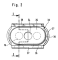
- the top view of the protective cap 26 with the sheet metal ring 33 shown in FIG. 2 shows the shape of the two parts.
- the section line of FIG. 1 and the positions of the stepped piston end 16 and its counterpart are indicated in dashed lines.
- the outline of the protective cap 26 and the sheet metal ring 33 corresponds to two semicircles connected with straight lines. In the rectilinear areas 38, the edge 37 is bent at an acute angle to the viewer, in the curves 39 it lies flat against the edge of the protective cap.
Landscapes
- Engineering & Computer Science (AREA)
- Mechanical Engineering (AREA)
- General Engineering & Computer Science (AREA)
- Transportation (AREA)
- Transmission Of Braking Force In Braking Systems (AREA)
- Braking Arrangements (AREA)
- Valve Device For Special Equipments (AREA)
- Hydraulic Control Valves For Brake Systems (AREA)
- Diaphragms And Bellows (AREA)
- Valves And Accessory Devices For Braking Systems (AREA)
- Regulating Braking Force (AREA)
Abstract
Description
- Die Erfindung betrifft einen lastabhängigen Twin-Bremskraftregler gemäß dem Oberbegriff des Anspruches 1.
- Ein gattungsgemäßer Twin-Bremskraftregler ist aus der DE-PS 33 15 763 bekannt. Dieser besitzt zur Ansteuerung der Regelkolben ein Wippelement, das rotationssymmetrisch ausgebildet ist. Die belasteten Enden der Regelkolben, das Wippelement und ein Teil eines am lastabhängig beweglichen Hebel befestigten Steuerstößels sind in einem zylindrischen Raum angeordnet, der spanabhebend in das Gehäuse gefräst ist. Um den Raum herum ist am Gehäuserand ein Schutzkappensitz eingefräst, um den eine rollmembranartige Schutzkappe eingespannt ist, die den zylindrischen Raum stirnseitig begrenzt. Durch ein zentrales Loch in der Schutzkappe führt der Steuerstößel von außen in diesen Raum. Am Steuerstößel umgreift die Schutzkappe einen umlaufenden Wulst.
- Die Verwendung von Wippelementen - welcher Form auch immer - hat sich bewährt bei der lastabhängigen Ansteuerung von Twin-Reglern. Damit die in den druckmittelfreien Raum ragenden Regelkolbenenden und ihre Dichtungen vor Verschmutzung geschützt sind, ist eine flexible, am Gehäuse befestigte Schutzkappe unentbehrlich. Das Gehäuse wird kostengünstig von einem Strang geschnitten, der im Gehäuseprofil gepreßt ist. Der zylindrische Raum jedoch muß genau wie der Schutzkappensitz nachträglich spanabhebend hergestellt werden. Das hat zur Folge, daß viel Material verschwendet wird und ein großer Arbeitsaufwand nötig ist.
- Die vorliegende Erfindung hat zur Aufgabe, einen gattungsgemäßen Bremskraftregler zu schaffen, bei dem wenig Abfallmetall und Arbeitszeit bei der Herstellung des Gehäuses anfallen.
- Diese Aufgabe wird gelöst durch die kennzeichnenden Merkmale des Hauptanspruches.
- Statt mit spanabhebenden Maßnahmen wird dem Gehäuse also gleich mit dem Strangpreßprofil die Form gegeben, die eine Befestigung der Schutzkappe erlaubt, so daß keine Nacharbeit nötig ist. Lediglich bei der Herstellung der Stufenbohrungen und der Druckmittelanschlüsse fallen noch Späne an.
- Die Schutzkappe selbst wird dabei vorteilhafterweise topfartig geformt, so daß ihr Rauminhalt das Volumen des zylindrischen Raums ersetzt.
- Weitere vorteilhafte Merkmale ergeben sich aus der folgenden Beschreibung einer bevorzugten Ausführung anhand von zwei Zeichnungen.
- Es zeigen:
- Fig. 1
- einen Schnitt durch einen erfindungsgemäßen Bremskraftregler;
- Fig. 2
- die Draufsicht auf eine Schutzkappe mit Blechring.
- Der in Fig. 1 dargestellte Bremskraftregler ist im Schnitt durch eine Regeleinheit dargestellt. Eine zweite identische Regeleinheit befindet sich - nicht sichtbar - parallel angeordnet hinter der ersten. Im Bereich der Ansteuerungsvorrichtung ist die Schnittebene in die Symmetrieachse versetzt, wie in Fig. 2 durch eine gestrichelte Linie angedeutet ist.
- Der Bremskraftregler besitzt im Gehäuse 1 die Bohrung 2, in welcher mit Hilfe der Führungshülse 3 und des Sprengrings 4 der Stufenkolben 5 axial verschiebbar geführt ist. Der Stufenkolben 5 ist gegen die Wand der Bohrung 2 und die Führungshülse 3 mit den Dichtungsmanschetten 6 bzw. 7 abgedichtet. Er besitzt eine Axialbohrung 8, in welcher sich das Ventilschließglied 9 befindet, das mit dem Ventilsitz 10 zusammen als Regelventil zwischen Einlaßraum 11 und Auslaßraum 12 wirkt. Dazu ist das Ventilschließglied 9 von der Druckfeder 13 in Schließrichtung belastet und im dargestellten drucklosen Zustand durch den Stößel 14, der sich an der die Gehäusebohrung 2 begrenzenden Stirnwand 15 abstützt, von seinem Ventilsitz 10 abgehoben.
- Das dieser Stirnwand 15 abgewandte Ende 16 des Stufenkolbens 5 ragt aus der Gehäusebohrung 2 heraus in den druckmittelfreien Raum. Gemeinsam mit dem nicht gezeichneten Ende des zweiten Stufenkolbens wird er vom Wippelement 17 über die darin eingepaßte Kugel 18 in Öffnungsrichtung des Ventils 9, 10 beaufschlagt. Zur Stabilisierung der Lage des Wippelementes 17 ist zwischen ihm und dem Absatz 19 am Stufenkolben 5 die Druckfeder 20 angeordnet. Der Angriffspunkt 22 des Stößels 21 am Wippelement 17 liegt in der Mitte zwischen den beiden Regeleinheiten und zwar dichter am Gehäuse 1 als der Berührungspunkt der Kugel 18 mit dem Stufenkolbenende 16. Der Stößel 21 besitzt die Form eines Spitzkegels mit abgerunderter Spitze, desgleichen die Vertiefung 23, in welcher sich der Angriffspunkt 22 befindet. Allerdings ist der Öffnungswinkel der Vertiefung 23 größer als der des Stößels 21, so daß eine begrenzte Wippbewegung möglich ist. Der Stößel 21 ist mit dem Steuerhebel 24 verschraubt, welcher um das Gelenk 25 schwenkbar ist und von der lastabhängigen Kraft F beaufschlagt ist.
- An der Gehäusefläche 32 einerseits und am Stößel 21 andererseits liegt staubdicht die Schutzkappe 26 an. Sie ist aus flexiblem Material, beispielsweise Gummi, und mit der Hebelbewegung verformbar. Sie ist topfartig geformt und besitzt einen an der Gehäusefläche 32 anliegenden, tellerartigen umlaufenden Rand 27, der nach außen hin dicker wird. Der den Stößel 21 umgreifende Schutzkappenrand 34 ist zur Vermeidung von Verschleiß verstärkt und dem Stößelumfang angepaßt.
- Zur Befestigung der Schutzkappe 26 besitzen die zwei mit dem Gehäuse 1 im Strang gepreßten Gehäusefortsätze 28 und 29, die die Gehäusefläche 32 begrenzen, im Profil jeweils eine breite Nut 30 bzw. 31. Die Nuten 30 und 31 verlaufen quer zur Kolbenachse, parallel zu der Ebene, in der die Stufenkolben angeordnet sind, und befinden sich an den Gehäusefortsätzen 28 und 29 jeweils an der Seite, die dem Wippelement 17 zugewandt ist.
- Die Schutzkappe 26 ist mit dem gestanzten Blechring 33 an der Gehäusefläche 32 fixiert. Der Blechring 33 besitzt an seinen den Gehäusefortsätzen 28 und 29 zugewandten Längsseiten einen spitzwinklig nach außen umgebogenen Rand 37, während er mit seinem inneren Umfang flächig an die Wand 35 der Schutzkappe angepaßt ist, so daß sein Profil die Längsseiten entlang V-förmig ist.
- Die Befestigung der Schutzkappe 26 erfolgt, in dem der Blechring 33 mit der geknickten Kante 36 voran über die Schutzkappe 26 geführt wird und gegen das Gehäuse 1 gedrückt wird, bis der nach außen umgebogene Rand 37 in die Nuten 33 und 31 einschnappt. Die Nutbreite entspricht daher in etwa der Summe aus der Dicke des Tellerrandes 27 der Schutzkappe 26 und der axialen Abmessung des umgebogenen Randes 37 des Blechrings 33. Im eingebauten Zustand drückt der Blechring 33 die Schutzkappe staubdicht an die Gehäusefläche 32, in dem er sich an den Wänden 30' und 31' der Nuten 30 und 31 abstützt. Durch die Abschrägung der Nutwände 30' und 31' ist ein Toleranzausgleich bei variierender Dicke des Tellerrandes 27 möglich, indem der umgeknickte Rand 37 des Blechrings 33 mehr oder weniger tief einschert.
- Die in Fig. 2 dargestellte Draufsicht auf die Schutzkappe 26 mit dem Blechring 33 macht die Form der beiden Teile deutlich. In gestrichelten Linien sind zum einen die Schnittlinie von Fig. 1 und zum anderen die Positionen des Stufenkolbenendes 16 und seines Gegenstücks angedeutet. Der Grundriß von Schutzkappe 26 und Blechring 33 entspricht zwei mit geraden Linien verbundenen Halbkreisen. In den geradlinigen Bereichen 38 ist der Rand 37 spitzwinklig zum Betrachter hin umgebogen, in den Rundungen 39 liegt er flach am Schutzkappenrand an.
-
- 1
- Gehäuse
- 2
- Gehäusebohrung
- 3
- Führungshülse
- 4
- Sprengring
- 5
- Stufenkolben
- 6
- Dichtungsmanschette
- 7
- Dichtungsmanschette
- 8
- Axialbohrung
- 9
- Ventilschließglied
- 10
- Ventilsitz
- 11
- Einlaßraum
- 12
- Auslaßraum
- 13
- Druckfeder
- 14
- Ventilstößel
- 15
- Stirnwand
- 16
- Stufenkolbenende
- 17
- Wippelement
- 18
- Kugel
- 19
- Absatz
- 20
- Druckfeder
- 21
- Stößel
- 22
- Angriffspunkt
- 23
- Vertiefung
- 24
- Steuerhebel
- 25
- Gelenk
- 26
- Schutzkappe
- 27
- Tellerrand
- 28
- Gehäusefortsatz
- 29
- Gehäusefortsatz
- 30
- Nut
- 30'
- Nutwand
- 31
- Nut
- 31'
- Nutwand
- 32
- Gehäusefläche
- 33
- Blechring
- 34
- Schutzkappenrand
- 35
- Schutzkappenwand
- 36
- geknickte Kante
- 37
- Rand
- 38
- geradliniger Bereich
- 39
- Rundung
Claims (9)
- Lastabhängiger Twin-Bremskraftregler für eine druckmittelbetätigte Bremsanlage, der in einem aus einem gepreßten Strang hergestellten Gehäuse (1) zwei nebeneinander angeordnete Bohrungen (2) mit je einem abgedichtet aus der Bohrung (2) ragenden Stufenkolben (5) aufweist, wobei die herausragenden Enden (16) der Stufenkolben von je einer Seite eines Wippelementes (17) belastet werden, das in seiner Mitte von einem Stößel (21) beaufschlagt wird, der fest mit einem lastabhängig beweglichen Steuerhebel (24) verbunden ist, wobei der Bremskraftregler außerdem eine flexible Schutzkappe (26) besitzt, die einen Bereich vor Schmutz schützt, in welchem die herausragenden Enden (16) des Stufenkolbens, das Wippelement (17) und zumindest ein Teil des Stößels (21) angeordnet sind, dadurch gekennzeichnet, daß das Gehäuse (1) an der Seite, auf welcher die Stufenkolben (5) herausragen, zwei Fortsätze (28,29) mit je einer geradlinigen Nut (30,31) aufweist, daß die Nuten (30,31) gleich breit und gleich tief sind parallel zur Verbindungslinie der beiden Stufenkolbenenden (16) verlaufen und sich in zwei zueinander gewandten Flächen der Fortsätze (28,29) befinden, wobei die Fortsätze (28,29) samt Nuten (30,31) im Strangpreßprofil enthalten sind.
- Twin-Bremskraftregler nach Anspruch 1, dadurch gekennzeichnet, daß die Schutzkappe (26) topfartig gestaltet ist und einen tellerartigen Rand (27) sowie im Boden ein zentrales Loch (34) besitzt.
- Twin-Bremskraftregler nach Anspruch 2, dadurch gekennzeichnet, daß der Grundriß der Schutzkappe (26) die Form zweier durch gleichlange gerade Linien verbundener Halbkreise besitzt, wobei der Abstand der geraden Linien (38) voneinander am Ansatz des Tellerrandes (27) kleiner ist, als der kleinste Abstand der Gehäusefortsätze (28,29) und wobei der Durchmesser des Lochs im Boden dem des Stößels (21) angepaßt ist.
- Twin-Bremskraftregler nach Anspruch 2 oder Anspruch 3, dadurch gekennzeichnet, daß der Rand (34) des zentralen Lochs und/oder nach außen hin der Tellerrand (27) verdickt sind.
- Twin-Bremskraftregler nach Anspruch 2, 3 oder 4, dadurch gekennzeichnet, daß zur Befestigung der Schutzkappe (26) ein elastisch verformbarer Blechring (33) vorgesehen ist, dessen Innenform in Grundriß und axialer Neigung der Außenform der Topfwand (35) angepaßt ist und dessen Profil zumindest über einen Teil seines Umfangs dadurch V-förmig ist, daß ein Rand (37) spitzwinklig nach außen umgeknickt ist (36).
- Twin-Bremskraftregler nach Anspruch 5, dadurch gekennzeichnet, daß der umgeknickte Rand (37) sich zumindest über einen Teil der geradlinigen Bereiche (38) des Ringumfanges erstreckt und der Abstand der gegenüberliegenden Außenkanten des Blechrings (33) in diesen Bereichen (38) größer ist als der kleinste Abstand der Gehäusefortsätze (28,29) und kleiner als der Abstand der tiefsten Stellen der Nuten (30,31) voneinander und daß die axiale Abmessung zwischen der geknickten Kante (36) und der Außenkante des Blechringes (33) nicht größer ist als die Breite der Nuten (30,31) abzüglich der kleinsten Dicke des Tellerrandes (27).
- Twin-Bremskraftregler nach Anspruch 6, dadurch gekennzeichnet, daß im eingebauten Zustand der Tellerrand (27) der Schutzkappe (26) zwischen den Gehäusefortsätzen (28,29) flächig am Gehäuse (1) anliegt, daß der Blechring mit seiner geknickten Kante (36) den Tellerrand (27) ans Gehäuse (1) drückt, in dem er sich mit der Außenkante seines V-Profils an den Wänden (30',31') der Nuten (30,31) abstützt und daß durch das zentrale Loch der Schutzkappe der Stößel (21) geführt ist.
- Twin-Bremskraftregler nach Anspruch 7, dadurch gekennzeichnet, daß die Wände (30',31') der Nuten (30,31) zum Toleranzausgleich abgeschrägt sind.
- Verfahren zum Zusammenbau eines Twin-Bremskraftreglers nach Anspruch 7 oder 8, dadurch gekennzeichnet, daß der Blechring (33) auf die Schutzkappe (26) gesetzt wird und diese Anordnung zwischen den Gehäusefortsätzen (28,29) gegen das Gehäuse (1) gedrückt wird, bis der Blechring (33) in die Nuten (30,31) einrastet.
Applications Claiming Priority (3)
| Application Number | Priority Date | Filing Date | Title |
|---|---|---|---|
| DE4120358 | 1991-06-20 | ||
| DE4120358A DE4120358C2 (de) | 1991-06-20 | 1991-06-20 | Lastabhängiger Twin-Bremskraftregler |
| PCT/EP1992/000955 WO1993000237A1 (de) | 1991-06-20 | 1992-05-02 | Lastabhängiger twin-bremskraftregler |
Publications (2)
| Publication Number | Publication Date |
|---|---|
| EP0544848A1 EP0544848A1 (de) | 1993-06-09 |
| EP0544848B1 true EP0544848B1 (de) | 1995-01-25 |
Family
ID=6434362
Family Applications (1)
| Application Number | Title | Priority Date | Filing Date |
|---|---|---|---|
| EP92909292A Expired - Lifetime EP0544848B1 (de) | 1991-06-20 | 1992-05-02 | Lastabhängiger twin-bremskraftregler |
Country Status (6)
| Country | Link |
|---|---|
| US (1) | US5407256A (de) |
| EP (1) | EP0544848B1 (de) |
| JP (1) | JPH06500294A (de) |
| KR (1) | KR100220526B1 (de) |
| DE (2) | DE4120358C2 (de) |
| WO (1) | WO1993000237A1 (de) |
Families Citing this family (2)
| Publication number | Priority date | Publication date | Assignee | Title |
|---|---|---|---|---|
| US5788341A (en) * | 1995-06-06 | 1998-08-04 | Itt Automotive Electrical Systems, Inc. | Vehicle brake |
| DE19634584A1 (de) * | 1996-08-27 | 1998-03-05 | Teves Gmbh Alfred | Lastabhängiger Bremskraftregler |
Family Cites Families (8)
| Publication number | Priority date | Publication date | Assignee | Title |
|---|---|---|---|---|
| FR2248182B1 (de) * | 1973-10-18 | 1976-06-18 | Dba | |
| US4101176A (en) * | 1975-04-01 | 1978-07-18 | Societe Anonyme Dba | Braking correction device |
| FR2383048A1 (fr) * | 1977-03-11 | 1978-10-06 | Dba | Compensateur de freinage |
| DE2927423C2 (de) * | 1979-07-06 | 1984-08-23 | Alfred Teves Gmbh, 6000 Frankfurt | Zweikreisdruckregler |
| DE3012765A1 (de) * | 1980-04-02 | 1981-10-08 | Alfred Teves Gmbh, 6000 Frankfurt | Zweikreis-druckregler fuer hydraulische bremsanlagen |
| DE3315763A1 (de) * | 1983-04-30 | 1984-10-31 | Alfred Teves Gmbh, 6000 Frankfurt | Bremsdrucksteuereinheit fuer eine zweikreis-fahrzeugbremsanlage |
| DE3602863A1 (de) * | 1986-01-31 | 1987-08-06 | Teves Gmbh Alfred | Bremsdrucksteuereinheit fuer eine druckmittelbetaetigbare fahrzeugbremsanlage |
| FR2617938B1 (fr) * | 1987-07-06 | 1990-02-09 | Peugeot | Joint d'etancheite a soufflet |
-
1991
- 1991-06-20 DE DE4120358A patent/DE4120358C2/de not_active Expired - Fee Related
-
1992
- 1992-05-02 EP EP92909292A patent/EP0544848B1/de not_active Expired - Lifetime
- 1992-05-02 DE DE59201294T patent/DE59201294D1/de not_active Expired - Lifetime
- 1992-05-02 US US07/969,245 patent/US5407256A/en not_active Expired - Fee Related
- 1992-05-02 WO PCT/EP1992/000955 patent/WO1993000237A1/de not_active Ceased
- 1992-05-02 JP JP4508537A patent/JPH06500294A/ja active Pending
- 1992-05-02 KR KR1019930700498A patent/KR100220526B1/ko not_active Expired - Fee Related
Also Published As
| Publication number | Publication date |
|---|---|
| US5407256A (en) | 1995-04-18 |
| KR930701305A (ko) | 1993-06-11 |
| DE4120358A1 (de) | 1992-12-24 |
| JPH06500294A (ja) | 1994-01-13 |
| DE59201294D1 (de) | 1995-03-09 |
| KR100220526B1 (ko) | 1999-09-15 |
| WO1993000237A1 (de) | 1993-01-07 |
| DE4120358C2 (de) | 1995-03-30 |
| EP0544848A1 (de) | 1993-06-09 |
Similar Documents
| Publication | Publication Date | Title |
|---|---|---|
| EP3183149B1 (de) | Elektromotor-pumpenaggregat | |
| EP3452344A1 (de) | Hydraulikzylinder, insbesondere hauptbremszylinder für hydraulische bremsanlagen | |
| EP0630448B1 (de) | Hydraulischer stossdämpfer | |
| EP3572669B1 (de) | Anschlussbaugruppe mit speisepumpe und elastischem element | |
| DE68903791T2 (de) | Ventil-uebersteuerungsmechanismus. | |
| DE1947117B2 (de) | Verfahren zum herstellen eines ventilschiebers | |
| DE2242204C3 (de) | Druckmittelbeaufschlagter Servomotor | |
| EP0666809B1 (de) | Hydraulisches druckminderventil | |
| DE3414006C2 (de) | Kolbenmembranpumpe | |
| WO1998022718A1 (de) | Pneumatischer oder hydraulischer stellmotor mit einer abschalteinrichtung | |
| CH654072A5 (de) | Radialkolbenpumpe. | |
| EP0901577B1 (de) | Manuell betätigbares hydraulisches vorsteuergerät | |
| EP0136492B1 (de) | Schwenkkolbenmotor | |
| DE19706059C2 (de) | Schieberventil | |
| EP3172102B1 (de) | Pneumatisches regelventil | |
| DE4120358C2 (de) | Lastabhängiger Twin-Bremskraftregler | |
| EP1416166B1 (de) | Endlagengedämpfter Pneumatikzylinder | |
| EP0702639B1 (de) | Hilfkraftlenkung für kraftfahrzeuge | |
| DE3012455C2 (de) | ||
| DE4317483A1 (de) | Kolben, insbesondere für den Servozylinder einer Hilfskraftlenkanlage | |
| DE19515950C2 (de) | Gleitdichtung in einem pneumatischen Mehrstellungsventil | |
| DE2810062C2 (de) | Regeleinrichtung | |
| EP0080565A2 (de) | Einrichtung zur Endabbremsung des Arbeitskolbens eines doppeltwirkenden Arbeitszylinders | |
| EP0088232B1 (de) | Schaltelement, insbesondere Federdruckbremse oder -Kupplung | |
| DE2926062A1 (de) | Druckreduziervorrichtung |
Legal Events
| Date | Code | Title | Description |
|---|---|---|---|
| PUAI | Public reference made under article 153(3) epc to a published international application that has entered the european phase |
Free format text: ORIGINAL CODE: 0009012 |
|
| 17P | Request for examination filed |
Effective date: 19930128 |
|
| AK | Designated contracting states |
Kind code of ref document: A1 Designated state(s): DE FR GB |
|
| RAP1 | Party data changed (applicant data changed or rights of an application transferred) |
Owner name: ITT AUTOMOTIVE EUROPE GMBH |
|
| 17Q | First examination report despatched |
Effective date: 19940318 |
|
| GRAA | (expected) grant |
Free format text: ORIGINAL CODE: 0009210 |
|
| AK | Designated contracting states |
Kind code of ref document: B1 Designated state(s): DE FR GB |
|
| GBT | Gb: translation of ep patent filed (gb section 77(6)(a)/1977) |
Effective date: 19950203 |
|
| REF | Corresponds to: |
Ref document number: 59201294 Country of ref document: DE Date of ref document: 19950309 |
|
| ET | Fr: translation filed | ||
| PLBE | No opposition filed within time limit |
Free format text: ORIGINAL CODE: 0009261 |
|
| 26N | No opposition filed | ||
| PGFP | Annual fee paid to national office [announced via postgrant information from national office to epo] |
Ref country code: GB Payment date: 20010426 Year of fee payment: 10 |
|
| REG | Reference to a national code |
Ref country code: GB Ref legal event code: IF02 |
|
| PG25 | Lapsed in a contracting state [announced via postgrant information from national office to epo] |
Ref country code: GB Free format text: LAPSE BECAUSE OF NON-PAYMENT OF DUE FEES Effective date: 20020502 |
|
| GBPC | Gb: european patent ceased through non-payment of renewal fee |
Effective date: 20020502 |
|
| PGFP | Annual fee paid to national office [announced via postgrant information from national office to epo] |
Ref country code: FR Payment date: 20030522 Year of fee payment: 12 |
|
| PGFP | Annual fee paid to national office [announced via postgrant information from national office to epo] |
Ref country code: DE Payment date: 20030531 Year of fee payment: 12 |
|
| PG25 | Lapsed in a contracting state [announced via postgrant information from national office to epo] |
Ref country code: DE Free format text: LAPSE BECAUSE OF THE APPLICANT RENOUNCES Effective date: 20030607 |
|
| PG25 | Lapsed in a contracting state [announced via postgrant information from national office to epo] |
Ref country code: FR Free format text: LAPSE BECAUSE OF NON-PAYMENT OF DUE FEES Effective date: 20050131 |
|
| REG | Reference to a national code |
Ref country code: FR Ref legal event code: ST |