EP0544406B1 - Improved anchor in automatic transmission bands - Google Patents
Improved anchor in automatic transmission bands Download PDFInfo
- Publication number
- EP0544406B1 EP0544406B1 EP92309773A EP92309773A EP0544406B1 EP 0544406 B1 EP0544406 B1 EP 0544406B1 EP 92309773 A EP92309773 A EP 92309773A EP 92309773 A EP92309773 A EP 92309773A EP 0544406 B1 EP0544406 B1 EP 0544406B1
- Authority
- EP
- European Patent Office
- Prior art keywords
- reaction
- strap
- strap member
- bracket
- brake band
- Prior art date
- Legal status (The legal status is an assumption and is not a legal conclusion. Google has not performed a legal analysis and makes no representation as to the accuracy of the status listed.)
- Expired - Lifetime
Links
Images


Classifications
-
- F—MECHANICAL ENGINEERING; LIGHTING; HEATING; WEAPONS; BLASTING
- F16—ENGINEERING ELEMENTS AND UNITS; GENERAL MEASURES FOR PRODUCING AND MAINTAINING EFFECTIVE FUNCTIONING OF MACHINES OR INSTALLATIONS; THERMAL INSULATION IN GENERAL
- F16D—COUPLINGS FOR TRANSMITTING ROTATION; CLUTCHES; BRAKES
- F16D65/00—Parts or details
- F16D65/02—Braking members; Mounting thereof
- F16D65/04—Bands, shoes or pads; Pivots or supporting members therefor
- F16D65/06—Bands, shoes or pads; Pivots or supporting members therefor for externally-engaging brakes
- F16D65/065—Brake bands
- F16D65/067—Brake bands with means for mounting, e.g. end connection members
-
- B—PERFORMING OPERATIONS; TRANSPORTING
- B60—VEHICLES IN GENERAL
- B60K—ARRANGEMENT OR MOUNTING OF PROPULSION UNITS OR OF TRANSMISSIONS IN VEHICLES; ARRANGEMENT OR MOUNTING OF PLURAL DIVERSE PRIME-MOVERS IN VEHICLES; AUXILIARY DRIVES FOR VEHICLES; INSTRUMENTATION OR DASHBOARDS FOR VEHICLES; ARRANGEMENTS IN CONNECTION WITH COOLING, AIR INTAKE, GAS EXHAUST OR FUEL SUPPLY OF PROPULSION UNITS IN VEHICLES
- B60K17/00—Arrangement or mounting of transmissions in vehicles
-
- F—MECHANICAL ENGINEERING; LIGHTING; HEATING; WEAPONS; BLASTING
- F16—ENGINEERING ELEMENTS AND UNITS; GENERAL MEASURES FOR PRODUCING AND MAINTAINING EFFECTIVE FUNCTIONING OF MACHINES OR INSTALLATIONS; THERMAL INSULATION IN GENERAL
- F16D—COUPLINGS FOR TRANSMITTING ROTATION; CLUTCHES; BRAKES
- F16D65/00—Parts or details
- F16D65/02—Braking members; Mounting thereof
- F16D65/04—Bands, shoes or pads; Pivots or supporting members therefor
Definitions
- This invention relates to a transmission brake band for use in an automatic transmission.
- a driving shaft extends from the torque converter into the transmission housing to a unit having one or more clutch drums around which are arranged either single-wrap or double-wrap brake bands. It is the function of the brake band, through the function of suitable hydraulic controls to effect gear changes and also control the direction of rotation of the output shaft from the transmission to the differential for the driving wheels of the vehicle.
- Single-wrap brake bands are currently available in two distinct styles.
- the most commonly known single-wrap brake band is usually formed from a strip of sheet steel or similar material, having at its ends brackets formed from separate forgings, castings or stampings.
- the brackets are suitably secured to the strap material by spot welding or similar methods as shown in US-A-3 732 954.
- a unitary single-wrap brake band has been designed which utilizes a single piece of material wherein the brackets are extruded or formed from double thicknesses of the base metal at the ends of the strap member.
- An example of a brake band of this type of structure is disclosed in our EP-A-0 464 995.
- each brake band have an actuation or apply end for receiving an apply piston and a reaction or anchor end which is operatively connected to a reaction member located in the transmission.
- reaction members may be of the tangential type which comprise a stationary plunger or stop member acting against the anchor end of the brake band, while other reaction members may be the reaction pin type where the pin extends perpendicular to the clutch drum and strap member and extends into a reaction opening located in the anchor bracket of the brake band.
- a "volcano" type reaction bracket is commonly provided to engage the reaction pin.
- a typical volcano bracket consists of an extruded opening extending radially outwardly from the reaction bracket of the band.
- a bushing secured to the bracket may have a reaction opening formed therein to receive the free end of the reaction pin, thus providing the anchored end of the brake band during use of the band in the automatic transmission.
- the opposite or apply end of the band is provided with an apply bracket for engaging the end of the apply plunger in the transmission that is hydraulically controlled to urge the band ends together and tighten the brake band around the clutch drum, thus stopping the rotation of the drum or otherwise altering the rotation of the drum or other member to change the gear ratio or alter the direction of rotation of the output shaft.
- the present invention achieves this goal by increasing the strength of the bracket and reducing the stress on the volcano so that premature failure of the bracket is quantitatively lessened.
- US-A-5083642 generally discloses a transmission brake band for use in an automatic transmission, comprising an elongated strap member defining a generally annular interior circumference and having an apply bracket located at one end of the strap member and a reaction bracket located at the opposed end of the strap member, and a friction lining adhered to the interior circumference of the strap member, the reaction bracket having a generally domed configuration with a reaction opening formed therethrough, the domed configuration separating the reaction opening from the friction lining to create a hollow area therebetween.
- the brake band of US-A-5083642 is a double wrap brake band having its reaction bracket formed as a separate stamping from the elongated, annular strap member and secured thereto as by welding and/or by projections on the one deformably engaging apertures in the other.
- the apply bracket is also formed as a separate stamping and likewise secured to the strap member.
- the aforementioned generally disclosed brake band is characterized in that the apply bracket is integrally formed from said one end of the strap member, and the reaction bracket is integrally formed from the opposed end of the strap member, the domed configuration of the reaction bracket being formed from the strap member to define a pocket in the annular interior circumference of the strap member, the pocket constituting the hollow area between the reaction opening and the friction lining, the domed configuration and the pocket being closed about its periphery flush with the strap member, the reaction opening extending through the domed configuration into the pocket to define a longitudinal axis, and the portion of the strap material forming the domed configuration immediately surrounding the reaction opening extending in a generally perpendicular direction away from the longitudinal axis of the reaction opening.
- a single strap of suitable metallic band material is provided. Both ends of the strap are bent upwardly and rearwardly over onto the strap member to form a double thickness of material at the ends of the strap. This area of double thickness is utilized to form the apply bracket at one end and the reaction bracket at the opposed end.
- the double layer of material at the reaction end is pressed or formed to create a dome configuration and is pierced or punched to produce the reaction opening in the bracket. There is no extrusion of the layers of the strap material.
- the periphery of the strap material which forms the reaction opening after the punching step is generally aligned in parallel with the curvilinear surface of the remainder of the band.
- the dome portion surrounding the reaction opening places the strap material in a generally perpendicular relationship to the reaction pin as it is inserted in the reaction opening.
- the reaction opening is not a volcano and is not created from upwardly bent, stressed or extruded portions of the band material.
- the two layers of material forming the bracket are secured together by commonly known methods such as clinch fastening or spot welding.
- the apply bracket for the band is further provided by any known method which allows for the end of the apply piston to engage and act to tighten the band around the clutch drum to apply the transmission band to the drum.
- a first embodiment of the present invention discloses a one-piece brake band, generally designed by the reference numeral 10, for use in a vehicle automatic transmission (not shown) which is formed from an elongated strap of material 12 defining a curved band 12 of determinate length.
- the opposed ends 14, 16 of the strap 12 are folded over and rearwardly back upon the strap 12 to create bracket members 18, 20, designed to engage an apply piston (not shown) and a reaction pin 22, respectively.
- the brake band 10 further includes a friction lining (not shown) suitably secured thereto by any acceptable method of adhesion.
- the apply bracket member 18 may be formed in any acceptable manner.
- the apply bracket shown in Fig. 1 is formed by folding the end 14 into a upwardly folded ridge 26 having a strengthening rib 28 on the side of the fold located below the contact point for an apply piston or pin.
- the folded ridge 26 may or may not include a depressed area (not shown) intended to form a pocket in the central area of the side opposite the strengthening rib 28.
- the depressed area is adapted to engage the end of the apply piston acting in a generally tangential direction to the clutch drum.
- the end 14 with ridge 26 and strengthening rib 28 are folded over the strap 12 and secured to the strap, preferably in a simultaneous manufacturing step with the folding and forming operation, by commonly accepted methods such as clinch fastening 30.
- the present invention primarily resides in the end 16 which forms the bracket reaction member 20.
- the end 16 is formed by folding the strap member 12 upwardly and rearwardly upon itself.
- a reaction pin opening 32 is punched or pierced through both layers of strap material from the interior strap surface 34 and an annular peripheral dome 36 is formed surrounding the opening 32.
- the reaction pin shown in ghost as 38, engages both layers of the strap material formed in the dome 36 at the reaction opening 32.
- the surface 37 of the dome 36 immediately proximate the reaction opening 32 is preferably aligned in a generally parallel relationship with the curvilinear surface of the strap member 12.
- the reaction bracket member 20 is fastened to the strap 12 by clinched fasteners 40 which are similar to the fasteners 30 utilized with the apply bracket. Although clinched fasteners are shown, the layers could also be spot welded together if desired.
- an alternative embodiment of the present invention discloses a one-piece brake band, generally designated by the reference numeral 110, for use in a vehicle automatic transmission (not shown) which is formed from an elongated strap of material 112 defining a curved band 112 of determinate length.
- the opposed ends 114, 116 of the strap 112 are folded over and rearwardly back upon the strap 112 to create bracket members 118, 120, designed to engage an apply piston (not shown) and a reaction pin 122, respectively.
- the brake band 110 further includes a friction lining (not shown) suitably secured thereto by any acceptable method of adhesion.
- the apply bracket member 118 may be formed in any acceptable manner.
- the apply bracket shown in Fig. 4 is formed by folding the end 114 into an upwardly folded ridge 126 having a strengthening rib 128 on the side of the fold located below the contact point for an apply piston or pin.
- the folded ridge 126 may or may not include a depressed area (not shown) intended to form a pocket in the central area of the side opposite the strengthening rib 128.
- the depressed area is adapted to engage the end of the apply piston acting in a generally tangential direction to the clutch drum.
- the end 114 with ridge 126 and strengthening rib 128 are folded over the strap 112 and secured to the strap, preferably in a simultaneous manufacturing step with the folding and forming operation, by commonly accepted methods such as clinch fastening 130.
- Figs. 5-6 detail the alternative embodiment of the reaction bracket member 120.
- the reaction bracket member is generally formed as a four sided dome 136 surrounding the reaction pin opening 132.
- the dome 136 is formed to have two sides 135 extending generally parallel with the length of the strap 112 and two sides 137 extending transverse to the length of the strap 112. It has been found that the four sided dome provides even greater enhanced strength characteristics in engaging the reaction pin 138.
- the pierced dome reaction bracket of the present invention provides for greater latitude in positioning of the reaction pin within the reaction opening and further, provides for greater strength in retaining the reaction pin in position without premature failure of the brake band.
Landscapes
- Engineering & Computer Science (AREA)
- General Engineering & Computer Science (AREA)
- Mechanical Engineering (AREA)
- Chemical & Material Sciences (AREA)
- Combustion & Propulsion (AREA)
- Transportation (AREA)
- Braking Arrangements (AREA)
- Gear-Shifting Mechanisms (AREA)
Description
- This invention relates to a transmission brake band for use in an automatic transmission.
- In conventional vehicle automatic transmissions of the torque converter type, a driving shaft extends from the torque converter into the transmission housing to a unit having one or more clutch drums around which are arranged either single-wrap or double-wrap brake bands. It is the function of the brake band, through the function of suitable hydraulic controls to effect gear changes and also control the direction of rotation of the output shaft from the transmission to the differential for the driving wheels of the vehicle.
- The present invention will be described in an embodiment intended to be utilized with a single-wrap brake band. However, the embodiment so described in this patent application is intended to be illustrative and is not intended to be limiting upon the use of this invention with transmission brake bands of all designs and styles.
- Single-wrap brake bands are currently available in two distinct styles. The most commonly known single-wrap brake band is usually formed from a strip of sheet steel or similar material, having at its ends brackets formed from separate forgings, castings or stampings. The brackets are suitably secured to the strap material by spot welding or similar methods as shown in US-A-3 732 954. More recently, a unitary single-wrap brake band has been designed which utilizes a single piece of material wherein the brackets are extruded or formed from double thicknesses of the base metal at the ends of the strap member. An example of a brake band of this type of structure is disclosed in our EP-A-0 464 995.
- Regardless of how the brake band and bracket members are formed, it is a requisite that each brake band have an actuation or apply end for receiving an apply piston and a reaction or anchor end which is operatively connected to a reaction member located in the transmission. Various types of automatic transmissions utilize different types of reaction members. Some reaction members may be of the tangential type which comprise a stationary plunger or stop member acting against the anchor end of the brake band, while other reaction members may be the reaction pin type where the pin extends perpendicular to the clutch drum and strap member and extends into a reaction opening located in the anchor bracket of the brake band.
- Where a reaction pin is used as the reaction member in the transmission band, a "volcano" type reaction bracket is commonly provided to engage the reaction pin. A typical volcano bracket consists of an extruded opening extending radially outwardly from the reaction bracket of the band. Alternatively, a bushing secured to the bracket may have a reaction opening formed therein to receive the free end of the reaction pin, thus providing the anchored end of the brake band during use of the band in the automatic transmission. The opposite or apply end of the band is provided with an apply bracket for engaging the end of the apply plunger in the transmission that is hydraulically controlled to urge the band ends together and tighten the brake band around the clutch drum, thus stopping the rotation of the drum or otherwise altering the rotation of the drum or other member to change the gear ratio or alter the direction of rotation of the output shaft. Due to the close tolerances required for proper function between the free end of the reaction pin and the opening of the volcano, many problems have been encountered in which the volcano opening fails prematurely during testing or operation of transmission. For instance, if the reaction pin is not fully engaged with the volcano opening the open edges of the volcano may chip, splinter and crack.
- Our aforementioned copending application EP-A-0 464 995 approaches the stress failure problems of such volcano brackets by providing a single piece brake band with an anchor embossment extruded from a double thickness of the strap material to produce a volcano type reaction bracket at one end of the brake band. The strap material is folded upon itself to form the double-layer and the volcano opening is formed by piercing the double layer of material to extrude the layers and form a tapered opening. The two layers of strap material are then secured together by clinch fastening, spot welding or other adequate means.
- While the extruded volcano opening has provided for enhanced strength characteristics and has significantly reduced the number of stress failures in such volcano anchor brackets, it remains desirable to further reduce the risk of failure of volcano reaction openings. Problems with stress fractures and failures are still encountered, especially in situations where the reaction pin is not fully inserted through the volcano opening and forces are exerted at the upraised edges of the volcano opening.
- Therefore, it is an object of this invention to provide a reaction bracket having enhanced strength characteristics to overcome the possibility of premature failures of the brake band. The present invention achieves this goal by increasing the strength of the bracket and reducing the stress on the volcano so that premature failure of the bracket is quantitatively lessened.
- Another example of the prior art is featured in US-A-5083642 which generally discloses a transmission brake band for use in an automatic transmission, comprising an elongated strap member defining a generally annular interior circumference and having an apply bracket located at one end of the strap member and a reaction bracket located at the opposed end of the strap member, and a friction lining adhered to the interior circumference of the strap member, the reaction bracket having a generally domed configuration with a reaction opening formed therethrough, the domed configuration separating the reaction opening from the friction lining to create a hollow area therebetween.
- More particularly, the brake band of US-A-5083642 is a double wrap brake band having its reaction bracket formed as a separate stamping from the elongated, annular strap member and secured thereto as by welding and/or by projections on the one deformably engaging apertures in the other. The apply bracket is also formed as a separate stamping and likewise secured to the strap member.
- The stated object of the invention is achieved, in accordance with the present invention as claimed, in that the aforementioned generally disclosed brake band is characterized in that the apply bracket is integrally formed from said one end of the strap member, and the reaction bracket is integrally formed from the opposed end of the strap member, the domed configuration of the reaction bracket being formed from the strap member to define a pocket in the annular interior circumference of the strap member, the pocket constituting the hollow area between the reaction opening and the friction lining, the domed configuration and the pocket being closed about its periphery flush with the strap member, the reaction opening extending through the domed configuration into the pocket to define a longitudinal axis, and the portion of the strap material forming the domed configuration immediately surrounding the reaction opening extending in a generally perpendicular direction away from the longitudinal axis of the reaction opening.
- In preparations for forming a preferred brake band utilizing the domed bracket of the present invention, a single strap of suitable metallic band material is provided. Both ends of the strap are bent upwardly and rearwardly over onto the strap member to form a double thickness of material at the ends of the strap. This area of double thickness is utilized to form the apply bracket at one end and the reaction bracket at the opposed end. Once the strap material has been folded upon itself, the double layer of material at the reaction end is pressed or formed to create a dome configuration and is pierced or punched to produce the reaction opening in the bracket. There is no extrusion of the layers of the strap material. Rather, the periphery of the strap material which forms the reaction opening after the punching step is generally aligned in parallel with the curvilinear surface of the remainder of the band. The dome portion surrounding the reaction opening places the strap material in a generally perpendicular relationship to the reaction pin as it is inserted in the reaction opening. Thus, the reaction opening is not a volcano and is not created from upwardly bent, stressed or extruded portions of the band material. Simultaneously, the two layers of material forming the bracket are secured together by commonly known methods such as clinch fastening or spot welding. The apply bracket for the band is further provided by any known method which allows for the end of the apply piston to engage and act to tighten the band around the clutch drum to apply the transmission band to the drum.
- In order that the present invention may be well understood there will now be described two preferred embodiments thereof, given by way of example, reference being made to the accompanying drawings, in which
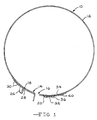
- Fig. 1 is an elevated side view of a transmission brake band embodying the present invention;
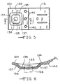
- Fig. 2 is a partial top plan view of the reaction bracket for the transmission brake band of Fig. 1;
- Fig. 3 is a sectional view taken along line 3-3 of Fig. 2;
- Fig. 4 is an elevational side view of an alternative embodiment of the transmission brake band of the present invention;
- Fig. 5 is a top plan view of the reaction bracket of the transmission brake band of Fig. 4; and,
- Fig. 6 is a sectional view taken along lines 6-6 of Fig. 5.
- Whilst the invention will be described with regard to Figs. 1-6 which all reference a one-piece single-wrap brake band, it is not intended that this description of the invention in use with a single-wrap one-piece brake band be necessarily limiting upon the envisioned range of embodiments for the present invention.
- Referring now to Figs. 1-3, a first embodiment of the present invention discloses a one-piece brake band, generally designed by the
reference numeral 10, for use in a vehicle automatic transmission (not shown) which is formed from an elongated strap ofmaterial 12 defining acurved band 12 of determinate length. Theopposed ends strap 12 are folded over and rearwardly back upon thestrap 12 to createbracket members brake band 10 further includes a friction lining (not shown) suitably secured thereto by any acceptable method of adhesion. - The apply
bracket member 18 may be formed in any acceptable manner. The apply bracket shown in Fig. 1 is formed by folding theend 14 into a upwardly foldedridge 26 having a strengtheningrib 28 on the side of the fold located below the contact point for an apply piston or pin. The foldedridge 26 may or may not include a depressed area (not shown) intended to form a pocket in the central area of the side opposite the strengtheningrib 28. The depressed area is adapted to engage the end of the apply piston acting in a generally tangential direction to the clutch drum. Theend 14 withridge 26 and strengtheningrib 28 are folded over thestrap 12 and secured to the strap, preferably in a simultaneous manufacturing step with the folding and forming operation, by commonly accepted methods such as clinch fastening 30. - Referring now to Figs. 2 and 3, the present invention primarily resides in the
end 16 which forms thebracket reaction member 20. Theend 16 is formed by folding thestrap member 12 upwardly and rearwardly upon itself. Areaction pin opening 32 is punched or pierced through both layers of strap material from theinterior strap surface 34 and an annularperipheral dome 36 is formed surrounding theopening 32. Thus, the reaction pin, shown in ghost as 38, engages both layers of the strap material formed in thedome 36 at the reaction opening 32. There is no extrusion of the strap material at the point of engagement with the reaction pin oranchor pin 38. Therefore, the full strength of the double layer ofstrap material 12 is utilized to anchor thebrake band 10 against movement induced by the apply pin against the applybracket member 18. The surface 37 of thedome 36 immediately proximate the reaction opening 32 is preferably aligned in a generally parallel relationship with the curvilinear surface of thestrap member 12. Thus the layers of strap material that act to engage theanchor pin 38 line generally perpendicular to the axis of theanchor pin 38 and, therefore, provide for enhancedbracket 20 strength against the forces applied by thepin 38 to the reaction opening 32. Thereaction bracket member 20 is fastened to thestrap 12 by clinchedfasteners 40 which are similar to thefasteners 30 utilized with the apply bracket. Although clinched fasteners are shown, the layers could also be spot welded together if desired. - Referring now to Figs. 4-6, an alternative embodiment of the present invention discloses a one-piece brake band, generally designated by the
reference numeral 110, for use in a vehicle automatic transmission (not shown) which is formed from an elongated strap ofmaterial 112 defining acurved band 112 of determinate length. The opposed ends 114, 116 of thestrap 112 are folded over and rearwardly back upon thestrap 112 to createbracket members brake band 110 further includes a friction lining (not shown) suitably secured thereto by any acceptable method of adhesion. - The apply
bracket member 118 may be formed in any acceptable manner. The apply bracket shown in Fig. 4 is formed by folding theend 114 into an upwardly foldedridge 126 having a strengtheningrib 128 on the side of the fold located below the contact point for an apply piston or pin. The foldedridge 126 may or may not include a depressed area (not shown) intended to form a pocket in the central area of the side opposite the strengtheningrib 128. The depressed area is adapted to engage the end of the apply piston acting in a generally tangential direction to the clutch drum. Theend 114 withridge 126 and strengtheningrib 128 are folded over thestrap 112 and secured to the strap, preferably in a simultaneous manufacturing step with the folding and forming operation, by commonly accepted methods such asclinch fastening 130. - Figs. 5-6 detail the alternative embodiment of the
reaction bracket member 120. In this embodiment of thebrake band 110 the reaction bracket member is generally formed as a foursided dome 136 surrounding thereaction pin opening 132. Thedome 136 is formed to have twosides 135 extending generally parallel with the length of thestrap 112 and twosides 137 extending transverse to the length of thestrap 112. It has been found that the four sided dome provides even greater enhanced strength characteristics in engaging thereaction pin 138. - The pierced dome reaction bracket of the present invention provides for greater latitude in positioning of the reaction pin within the reaction opening and further, provides for greater strength in retaining the reaction pin in position without premature failure of the brake band.
Claims (6)
- A transmission brake band for use in an automatic transmission, comprising an elongated strap member (12; 112) defining a generally annular interior circumference (34; 134) and having an apply bracket (18; 118) located at one end (14; 114) of the strap member (12; 112) and a reaction bracket (20; 120) located at the opposed end (16; 116) of the strap member (12; 112), and a friction lining adhered to the interior circumference (34; 134) of the strap member (12; 112), the reaction bracket (20; 120) having a generally domed configuration (36; 136) with a reaction opening (32; 132) formed therethrough, the domed configuration (36; 136) separating the reaction opening (32; 132) from the friction lining (24; 124) to create a hollow area therebetween; characterized in that the apply bracket (18; 118) is integrally formed from said one end (14; 114) of the strap member (12; 112), and the reaction bracket (20; 120) is integrally formed from the opposed end (16; 116) of the strap member (12; 112), the domed configuration (36; 136) of the reaction bracket (20; 120) being formed from the strap member (12; 112) to define a pocket in the annular interior circumference (34; 134) of the strap member (12; 112), the pocket constituting the hollow area between the reaction opening (32; 132) and the friction lining, the domed configuration (36; 136) and the pocket being closed about its periphery flush with the strap member (12; 112), the reaction opening (32; 132) extending through the domed configuration (36; 136) into the pocket to define a longitudinal axis, and the portion of the strap material forming the domed configuration (36; 136) immediately surrounding the reaction opening (32; 132) extending in a generally perpendicular direction away from the longitudinal axis of the reaction opening (32; 132).
- A brake band as claimed in claim 1, wherein the opposed end (16; 116) of the strap member (12; 112) is folded back upon itself to create a completely engaged double thickness of the strap material at said opposed end (16; 116) from which double thickness strap material the reaction bracket (20; 120) is formed.
- A brake band as claimed in claim 1 or claim 2, wherein said one end (14; 114) of the strap member (12; 112) is folded back upon itself to create a double thickness of the strap material at said one end (14; 114) from which double thickness strap material the apply bracket (18; 118) is formed.
- A brake band as claimed in any of the preceding claims, wherein the domed configuration (36; 136) immediately surrounding the periphery of the reaction opening (32; 132) is in a generally parallel relationship with the interior circumference (34; 134) created by the strap member (12; 112).
- A brake band as claimed in any of the preceding claims, wherein the domed configuration (36) immediately surrounding the periphery of the reaction opening (32) has a circumference spaced equidistantly around the reaction opening (32).
- A brake band as claimed in any of claims 1 to 4, wherein the domed configuration (136) immediately surrounding the periphery of the reaction opening (132) is of a generally square configuration having two sides (135) of the dome (136) generally parallel to the edges of the strap member (112) and the remaining two sides (137) of the dome (136) generally perpendicular to the edges of the strap member (112).
Applications Claiming Priority (2)
| Application Number | Priority Date | Filing Date | Title |
|---|---|---|---|
| US79821291A | 1991-11-26 | 1991-11-26 | |
| US798212 | 1991-11-26 |
Publications (2)
| Publication Number | Publication Date |
|---|---|
| EP0544406A1 EP0544406A1 (en) | 1993-06-02 |
| EP0544406B1 true EP0544406B1 (en) | 1995-10-04 |
Family
ID=25172814
Family Applications (1)
| Application Number | Title | Priority Date | Filing Date |
|---|---|---|---|
| EP92309773A Expired - Lifetime EP0544406B1 (en) | 1991-11-26 | 1992-10-26 | Improved anchor in automatic transmission bands |
Country Status (6)
| Country | Link |
|---|---|
| EP (1) | EP0544406B1 (en) |
| JP (1) | JP3448313B2 (en) |
| KR (1) | KR100280584B1 (en) |
| AU (1) | AU2700192A (en) |
| CA (1) | CA2082719A1 (en) |
| DE (1) | DE69205259T2 (en) |
Families Citing this family (2)
| Publication number | Priority date | Publication date | Assignee | Title |
|---|---|---|---|---|
| US5476160A (en) * | 1991-10-29 | 1995-12-19 | Borg-Warner Automotive, Inc. | Double-wrap brake band assembly |
| US20010008196A1 (en) | 2000-01-13 | 2001-07-19 | Kazuyuki Fujita | Band braking device, and method of manufacturing annular brake band |
Family Cites Families (3)
| Publication number | Priority date | Publication date | Assignee | Title |
|---|---|---|---|---|
| US5083642A (en) * | 1990-01-25 | 1992-01-28 | Advanced Friction Materials Company | Double wrap friction brake band and method of manufacture |
| US5078237A (en) * | 1990-06-28 | 1992-01-07 | Borg-Warner Automotive Transmission & Engine Components Corporation | Automatic transmission bands |
| CA2035918A1 (en) * | 1990-04-12 | 1991-10-13 | Christopher P. Puchalla | One-piece transmission band having the apply and reaction members integrally formed in the base material |
-
1992
- 1992-10-14 AU AU27001/92A patent/AU2700192A/en not_active Abandoned
- 1992-10-26 DE DE69205259T patent/DE69205259T2/en not_active Expired - Fee Related
- 1992-10-26 EP EP92309773A patent/EP0544406B1/en not_active Expired - Lifetime
- 1992-10-29 KR KR1019920019995A patent/KR100280584B1/en not_active Expired - Fee Related
- 1992-11-12 CA CA002082719A patent/CA2082719A1/en not_active Abandoned
- 1992-11-18 JP JP30860292A patent/JP3448313B2/en not_active Expired - Fee Related
Also Published As
| Publication number | Publication date |
|---|---|
| DE69205259T2 (en) | 1996-03-14 |
| DE69205259D1 (en) | 1995-11-09 |
| AU2700192A (en) | 1993-05-27 |
| KR930009816A (en) | 1993-06-21 |
| JPH05215235A (en) | 1993-08-24 |
| JP3448313B2 (en) | 2003-09-22 |
| EP0544406A1 (en) | 1993-06-02 |
| KR100280584B1 (en) | 2001-10-24 |
| CA2082719A1 (en) | 1993-05-27 |
Similar Documents
| Publication | Publication Date | Title |
|---|---|---|
| US4602706A (en) | Double wrap brake band | |
| US4757880A (en) | Strap configuration for a reverse double wrap band | |
| US5067227A (en) | Double wrap brake band and its manufacturing method | |
| EP0464995B1 (en) | Brake band for transmission assembly | |
| US5381876A (en) | Anchor in automatic transmission bands | |
| US5263557A (en) | Anchor for automatic transmission bands | |
| EP0544406A1 (en) | Improved anchor in automatic transmission bands | |
| KR100329687B1 (en) | Double-wrap brake band assembly | |
| US5347702A (en) | Method of producing a transmission brake band | |
| US4581803A (en) | Method of forming double wrap brake bands | |
| CA1248884A (en) | Bracket assembly for a double wrap band | |
| EP0540156B1 (en) | Double-wrap brake band assembly | |
| CA1248885A (en) | Strap configuration for a double wrap band | |
| US5346040A (en) | One-piece transmission band | |
| CA1248883A (en) | Bracket assembly for a double wrap band | |
| EP0451937B1 (en) | One-piece transmission band having the apply and reaction members integrally formed in the base material | |
| CA1195262A (en) | Bracket member for double wrap brake band | |
| EP0520614B1 (en) | One-piece transmission band | |
| CA2195514A1 (en) | Transmission band with anchor bracket having local coining at the anchor hole | |
| JPH09112603A (en) | Band brake |
Legal Events
| Date | Code | Title | Description |
|---|---|---|---|
| PUAI | Public reference made under article 153(3) epc to a published international application that has entered the european phase |
Free format text: ORIGINAL CODE: 0009012 |
|
| AK | Designated contracting states |
Kind code of ref document: A1 Designated state(s): DE ES FR GB IT |
|
| 17P | Request for examination filed |
Effective date: 19930908 |
|
| 17Q | First examination report despatched |
Effective date: 19940725 |
|
| GRAA | (expected) grant |
Free format text: ORIGINAL CODE: 0009210 |
|
| AK | Designated contracting states |
Kind code of ref document: B1 Designated state(s): DE ES FR GB IT |
|
| PG25 | Lapsed in a contracting state [announced via postgrant information from national office to epo] |
Ref country code: IT Free format text: LAPSE BECAUSE OF FAILURE TO SUBMIT A TRANSLATION OF THE DESCRIPTION OR TO PAY THE FEE WITHIN THE PRE;WARNING: LAPSES OF ITALIAN PATENTS WITH EFFECTIVE DATE BEFORE 2007 MAY HAVE OCCURRED AT ANY TIME BEFORE 2007. THE CORRECT EFFECTIVE DATE MAY BE DIFFERENT FROM THE ONE RECORDED.SCRIBED TIME-LIMIT Effective date: 19951004 Ref country code: ES Free format text: THE PATENT HAS BEEN ANNULLED BY A DECISION OF A NATIONAL AUTHORITY Effective date: 19951004 |
|
| ET | Fr: translation filed | ||
| REF | Corresponds to: |
Ref document number: 69205259 Country of ref document: DE Date of ref document: 19951109 |
|
| PLBE | No opposition filed within time limit |
Free format text: ORIGINAL CODE: 0009261 |
|
| 26N | No opposition filed | ||
| REG | Reference to a national code |
Ref country code: GB Ref legal event code: IF02 |
|
| PGFP | Annual fee paid to national office [announced via postgrant information from national office to epo] |
Ref country code: GB Payment date: 20030915 Year of fee payment: 12 |
|
| PGFP | Annual fee paid to national office [announced via postgrant information from national office to epo] |
Ref country code: FR Payment date: 20031003 Year of fee payment: 12 |
|
| PGFP | Annual fee paid to national office [announced via postgrant information from national office to epo] |
Ref country code: DE Payment date: 20031031 Year of fee payment: 12 |
|
| PG25 | Lapsed in a contracting state [announced via postgrant information from national office to epo] |
Ref country code: GB Free format text: LAPSE BECAUSE OF NON-PAYMENT OF DUE FEES Effective date: 20041026 |
|
| PG25 | Lapsed in a contracting state [announced via postgrant information from national office to epo] |
Ref country code: DE Free format text: LAPSE BECAUSE OF NON-PAYMENT OF DUE FEES Effective date: 20050503 |
|
| GBPC | Gb: european patent ceased through non-payment of renewal fee |
Effective date: 20041026 |
|
| PG25 | Lapsed in a contracting state [announced via postgrant information from national office to epo] |
Ref country code: FR Free format text: LAPSE BECAUSE OF NON-PAYMENT OF DUE FEES Effective date: 20050630 |
|
| REG | Reference to a national code |
Ref country code: FR Ref legal event code: ST |