EP0543337A2 - Double-sided safety gear - Google Patents
Double-sided safety gear Download PDFInfo
- Publication number
- EP0543337A2 EP0543337A2 EP92119625A EP92119625A EP0543337A2 EP 0543337 A2 EP0543337 A2 EP 0543337A2 EP 92119625 A EP92119625 A EP 92119625A EP 92119625 A EP92119625 A EP 92119625A EP 0543337 A2 EP0543337 A2 EP 0543337A2
- Authority
- EP
- European Patent Office
- Prior art keywords
- wedge
- working
- safety gear
- counter
- wedges
- Prior art date
- Legal status (The legal status is an assumption and is not a legal conclusion. Google has not performed a legal analysis and makes no representation as to the accuracy of the status listed.)
- Granted
Links
Images
Classifications
-
- B—PERFORMING OPERATIONS; TRANSPORTING
- B66—HOISTING; LIFTING; HAULING
- B66B—ELEVATORS; ESCALATORS OR MOVING WALKWAYS
- B66B5/00—Applications of checking, fault-correcting, or safety devices in elevators
- B66B5/02—Applications of checking, fault-correcting, or safety devices in elevators responsive to abnormal operating conditions
- B66B5/16—Braking or catch devices operating between cars, cages, or skips and fixed guide elements or surfaces in hoistway or well
- B66B5/18—Braking or catch devices operating between cars, cages, or skips and fixed guide elements or surfaces in hoistway or well and applying frictional retarding forces
- B66B5/22—Braking or catch devices operating between cars, cages, or skips and fixed guide elements or surfaces in hoistway or well and applying frictional retarding forces by means of linearly-movable wedges
Definitions
- the present invention relates to a safety gear e.g. for an elevator car or counterweight, said safety gear comprising at least one wedge chamber and at least one working wedge acting upon a guide rail of the elevator and activated by means of a transmission element.
- sliding safety gears are normally used as precautions when the elevator speed for some reason increases too much.
- the sliding safety gears grip the guide rails, of which there are usually two or four.
- the safety gears are mutually synchronized via separate synchronizing levers.
- the sliding safety gear is provided with a sliding surface which has a high friction coefficient and is pressed against the guide rail when the safety gear is activated, thus decelerating or stopping the elevator car by means of friction.
- the distance between the upper edges of the guide surfaces is equal to or greater than the distance between the lower edges of the corresponding guide surfaces.
- the force of the power means is generated by a spring. This patent does not accomplish compensation of the changes of friction on both sides but only on the side of the spring. Moreover, the clearances are relatively small.
- the double-sided safety gear of the invention is an improvement to the currently used safety gear, which was described above as an example of the state of the art.
- the object of the present invention is to eliminate the drawbacks mentioned.
- the safety gear of the invention has at least one counter wedge for each working wedge of the elevator, said counter wedge moving along a guide surface provided in the wedge chamber, and the counter wedge of the working wedge is on the same side of the guide rail as the working wedge in question.
- the safety gear has a frame 4 which is fixed to the elevator car unit 1 by means of bolts 2.
- the frame is provided with a wedge chamber 8, which houses working wedges 9 placed on either side of the guide rail 30.
- the upper and lower ends of the working wedges 9 differ in width because of their wedge-like shape.
- the safety gear is provided with adjusting screws 7 seated in the safety gear frame 4.
- the working wedges 9 are attached by their upper ends with synchronizing forks 31 via levers 37 to ropes or other lifting means. This safety gear can only grip during downward travel of the elevator car.
- the wedge chamber 8 is provided with guide surfaces 14 and 39, along which the counter wedge 10 moves so that the guide surfaces 14 and 39 are parallel to each other.
- the counter wedge 10 has a guide surface 13 provided with balls 15 on which the working wedge 9 moves.
- the distance of guide surface 13 from the guide rail 30 diminishes as you trace the guide surface by moving upwards along it, and, similarly, the distance of guide surface 15 from the guide rail 30 increases as you follow it in the upward direction.
- the counter wedge 10 moves along guide surface 14.
- the wedge chamber 8 is centered relative to the guide rail by means of screws 7.
- the friction between the guide surface of the wedge chamber and the counter wedge is reduced by means of balls 15, which convert the friction into rolling friction.
- the guide surfaces are provided with rolling slots 16.
- the guide surface between wedges 9 and 10 is provided with similar rolling slots 16.
- the wedge chamber is provided with retaining cotters 12 placed at the lower ends of the slots. At the upper ends the corresponding retaining cotters 11 are attached to the wedges 9.
- Balls 15 and 42 in slots 14 and 39 keep wedges 10 at the right distance from the wedge chamber.
- the rolling slots 17 and the guide pins 41 keep the wedges 9 at the right distance from the surface of the counter wedge 10.
- the vertical surface of the wedges 9 travelling along the elevator guide rail 30 are provided with separate braking surfaces 18 with friction characteristics that are better than those of the wedge material itself.
- the lower part of the working wedge 9 is provided with an adjusting screw 32, whose stop face is the bottom surface 33 of the counter wedge 10.
- synchronizing rods 34 Attached to the upper ends of the working wedges 9 are synchronizing rods 34, which are further attached to the synchronizing forks 31 and the levers 37.
- pressure springs 40 Between the wedge chamber 8 and the upper ends of the counter wedges 10 are pressure springs 40 which push the counter wedges 10 obliquely downwards.
- the pressure springs 40 are attached to the counter wedges 10 by retention screws 35.
- the stop faces 36 of the pressure springs 40 in the wedge chamber 8 are so inclined as to direct the spring force applied to the counter wedges 10 so that it will act in a direction parallel to guide surfaces 14 and 39.
- the wedge chamber 8 is provided with protecting plates (not shown) to precent the wedges from moving sideways out of the wedge chamber 8. At the same time, they protect the wedge chamber 8 againgst dirt and rubbish.
- the overspeed governor (not shown in the figure) is activated, causing the working wedges 9 of the safety gear to rise.
- the working wedges 9 act simultaneously in the same direction.
- the braking surfaces 18 of the working wedges 9 engage the elevator guide rail 30 and the working wedges 9 continue moving upwards in relation to the wedge chamber 8.
- the relative upward motion of the working wedge 9 in relation to the wedge chamber 8 also causes the counter wedges 10 to move upwards against the springs 40.
- the upward motion of the counter wedge 10 is less than that of the working wedge 9 because the total angle ⁇ of the counter wedge 10, i.e. the angle between surfaces 13 and 14, is larger than the angle ⁇ of the working wedge 9. This angle is the angle between surface 13 and the vertical direction.
- the magnitude of the difference between the motions of the counter wedge 10 and the working wedge 9 depends on the angle between the guide surfaces 13 and 14.
- the spring force of the spring 40 increases and also the friction between surface 18 and the guide rail 30 increases.
- the adjusting screw 32 hits the bottom 33 of the counter wedge 10, causing the upward motion to stop and the frictional force to remain constant. The motion stops because otherwise the counter wedge 10 would come clear of the guide surface 14, whereupon the normal force would disappear and so would the friction.
- the spring will then return the counter wedge 10 back against the guide surface 14.
- the safety gear is so constructed that the working wedges 9 touch the elevator guide rail 30 before the counter wedges 10 are stopped in their upper position. As the working wedges 9 rise due to friction towards the limit of their upper position, the counter wedge 10 is also pushed up due to friction against the spring force F.
- the frictional force obtained with spring force F between the wedges and the elevator guide rail 30 is very large, allowing a high braking power to be achieved. Because of angle ⁇ , only a small spring force is needed and therefore a sufficient gripping power is achieved with a small spring.
- the data indicating the need for safety gear action may be obtained e.g. from a tachometer monitoring the car motion.
- the wedges can be moved e.g. using electromagnets.
Abstract
Description
- The present invention relates to a safety gear e.g. for an elevator car or counterweight, said safety gear comprising at least one wedge chamber and at least one working wedge acting upon a guide rail of the elevator and activated by means of a transmission element.
- In elevators having a rated car speed exceeding 1 m/s, sliding safety gears are normally used as precautions when the elevator speed for some reason increases too much. The sliding safety gears grip the guide rails, of which there are usually two or four. In cases where each guide rail has its own sliding safety gear, the safety gears are mutually synchronized via separate synchronizing levers. The sliding safety gear is provided with a sliding surface which has a high friction coefficient and is pressed against the guide rail when the safety gear is activated, thus decelerating or stopping the elevator car by means of friction.
- Various elevator safety gear structures have been developed. One of the commonest is a large U-shaped spring made of spring steel, in which a wedge is thrust into the gap between the spring ends as it grips the guide rail. In addition, many safety gears have a separate release wedge by means of which the wedge is released from the guide rail after the safety gear action. The releasing is effected by raising the elevator car.
- An example of the state of the art is also Finnish patent no. 74686, corresponding to German patent DE 3715098 and American patent US 4819765. To stop the elevator car unit, both the car unit and the counterweight can be provided with safety gears e.g. as presented in FI patent 74686 and, to ensure safe operation in door zones, the overspeed governor can be provided with an electrically operated triggering device for switch-over to low speed. However, this is an expensive solution and takes up plenty of room because a safety gear is needed for the counterweight as well. In a sliding elevator safety gear according to this patent, standard parts are used and the wedge chamber is provided with a power means which imparts to the counter wedge a force acting substantially in the direction of the guide surface. The distance between the upper edges of the guide surfaces is equal to or greater than the distance between the lower edges of the corresponding guide surfaces. The force of the power means is generated by a spring. This patent does not accomplish compensation of the changes of friction on both sides but only on the side of the spring. Moreover, the clearances are relatively small.
- In certain countries, the elevator regulations have been revised to prevent the occurrence of the following accidents:
- An elevator car hits the ceiling of the elevator shaft after running up at an overspeed.
- A passenger is crushed by the doorway structures of an elevator that has left a floor with doors open.
- The double-sided safety gear of the invention is an improvement to the currently used safety gear, which was described above as an example of the state of the art. The object of the present invention is to eliminate the drawbacks mentioned. The safety gear of the invention has at least one counter wedge for each working wedge of the elevator, said counter wedge moving along a guide surface provided in the wedge chamber, and the counter wedge of the working wedge is on the same side of the guide rail as the working wedge in question.
- The preferred embodiments of the invention are presented in the other claims.
- The device of the invention has the advantages that
- the clearances are larger than in previously known solutions
- the variations in friction appearing on both sides of the guide rail can be eliminated, so the friction coefficient remains constant
- user safety is improved as well.
- In the following, the safety gear of the invention is described in detail by referring to the drawings, in which
- Fig. 1
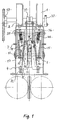
- presents the safety gear of the invention
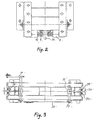
- Fig. 2
- presents the same safety gear in top view
- Fig. 3
- presents the safety gear of the invention in top view, showing a lever system, a synchronizing fork and a guide rail.
- The safety gear has a
frame 4 which is fixed to theelevator car unit 1 by means ofbolts 2. The frame is provided with awedge chamber 8, which houses workingwedges 9 placed on either side of theguide rail 30. The upper and lower ends of the workingwedges 9 differ in width because of their wedge-like shape. For each workingwedge 9 there is acounter wedge 10, which also has a wedge-like shape, and these twocounter wedges 10 are placed on either side of theguide rail 30. For lateral adjustment of thewedge chamber 8, the safety gear is provided with adjustingscrews 7 seated in thesafety gear frame 4. The workingwedges 9 are attached by their upper ends with synchronizingforks 31 vialevers 37 to ropes or other lifting means. This safety gear can only grip during downward travel of the elevator car. Thewedge chamber 8 is provided withguide surfaces 14 and 39, along which thecounter wedge 10 moves so that theguide surfaces 14 and 39 are parallel to each other. Thecounter wedge 10 has a guide surface 13 provided withballs 15 on which the workingwedge 9 moves. The distance of guide surface 13 from theguide rail 30 diminishes as you trace the guide surface by moving upwards along it, and, similarly, the distance ofguide surface 15 from theguide rail 30 increases as you follow it in the upward direction. Correspondingly, thecounter wedge 10 moves alongguide surface 14. Thewedge chamber 8 is centered relative to the guide rail by means ofscrews 7. The friction between the guide surface of the wedge chamber and the counter wedge is reduced by means ofballs 15, which convert the friction into rolling friction. To hold theballs 15 in place, the guide surfaces are provided with rolling slots 16. The guide surface betweenwedges retaining cotters 12 placed at the lower ends of the slots. At the upper ends the corresponding retaining cotters 11 are attached to thewedges 9.Balls 15 and 42 inslots 14 and 39 keepwedges 10 at the right distance from the wedge chamber. Therolling slots 17 and the guide pins 41 keep thewedges 9 at the right distance from the surface of thecounter wedge 10. The vertical surface of thewedges 9 travelling along theelevator guide rail 30 are provided withseparate braking surfaces 18 with friction characteristics that are better than those of the wedge material itself. The lower part of the workingwedge 9 is provided with an adjustingscrew 32, whose stop face is the bottom surface 33 of thecounter wedge 10. Attached to the upper ends of the workingwedges 9 are synchronizingrods 34, which are further attached to the synchronizingforks 31 and thelevers 37. Between thewedge chamber 8 and the upper ends of thecounter wedges 10 are pressure springs 40 which push thecounter wedges 10 obliquely downwards. The pressure springs 40 are attached to thecounter wedges 10 byretention screws 35. The stop faces 36 of the pressure springs 40 in thewedge chamber 8 are so inclined as to direct the spring force applied to thecounter wedges 10 so that it will act in a direction parallel to guidesurfaces 14 and 39. Furthermore, thewedge chamber 8 is provided with protecting plates (not shown) to precent the wedges from moving sideways out of thewedge chamber 8. At the same time, they protect thewedge chamber 8 againgst dirt and rubbish. - Below is a brief description of the operation of the safety gear of the invention. When the speed of the elevator car during downward travel increases too much, the overspeed governor (not shown in the figure) is activated, causing the working
wedges 9 of the safety gear to rise. The workingwedges 9 act simultaneously in the same direction. As the elevator car and, along with it, thewedge chamber 8 travel downwards in relation to thewedges 9, the braking surfaces 18 of the workingwedges 9 engage theelevator guide rail 30 and the workingwedges 9 continue moving upwards in relation to thewedge chamber 8. The relative upward motion of the workingwedge 9 in relation to thewedge chamber 8 also causes thecounter wedges 10 to move upwards against the springs 40. The upward motion of thecounter wedge 10 is less than that of the workingwedge 9 because the total angle β of thecounter wedge 10, i.e. the angle betweensurfaces 13 and 14, is larger than the angle α of the workingwedge 9. This angle is the angle between surface 13 and the vertical direction. The magnitude of the difference between the motions of thecounter wedge 10 and the workingwedge 9 depends on the angle between the guide surfaces 13 and 14. During this motion, the spring force of the spring 40 increases and also the friction betweensurface 18 and theguide rail 30 increases. The adjustingscrew 32 hits the bottom 33 of thecounter wedge 10, causing the upward motion to stop and the frictional force to remain constant. The motion stops because otherwise thecounter wedge 10 would come clear of theguide surface 14, whereupon the normal force would disappear and so would the friction. The spring will then return thecounter wedge 10 back against theguide surface 14. After the safety gear action, when the elevator is released by raising the car, a motion in the opposite direction occurs and the springs 40 push the wedges back into place. The safety gear is so constructed that the workingwedges 9 touch theelevator guide rail 30 before thecounter wedges 10 are stopped in their upper position. As the workingwedges 9 rise due to friction towards the limit of their upper position, thecounter wedge 10 is also pushed up due to friction against the spring force F. By virtue of the wedge action, the frictional force obtained with spring force F between the wedges and theelevator guide rail 30 is very large, allowing a high braking power to be achieved. Because of angle α, only a small spring force is needed and therefore a sufficient gripping power is achieved with a small spring. In the future, when the regulations permit, the data indicating the need for safety gear action may be obtained e.g. from a tachometer monitoring the car motion. The wedges can be moved e.g. using electromagnets. - It is obvious to a person skilled in the art that different embodiments of the invention are not restricted to the examples described above, but that they may instead be varied within the scope of the following claims.
Claims (5)
- Safety gear e.g. for an elevator car or counterweight, comprising at least one wedge chamber (8) and at least one working wedge (9) acting on an elevator guide rail (30) and activated by means of a transmission element, characterized in that the safety gear has for each working wedge (9) at least one counter wedge (10) moving along guide surfaces (14 and 39) provided in the wedge chamber (8), and that the counter wedge (10) of the working wedge (9) is on the same side of the guide rail as the working wedge (9) in question.
- Safety gear according to claim 1, characterized in that the angle (β) between the guide surface (14) provided in the wedge chamber (8) to guide the counter wedge (10) and the guide surface (13) on the side facing the working wedge (9) is larger than the angle (α) between the vertical direction and the working wedge surface facing the counter wedge (10), so that the upward motion of the counter wedge (10) is less than that of the working wedge (9).
- Safety gear according to claim 1 or 2, characterized in that it has two working wedges (9), which are placed on opposite sides of the guide rail (30) and are symmetrical relative to the guide rail, and that the working wedges (9) act simultaneously and in the same direction during gripping.
- Safety gear according to claim 1, 2 or 3, characterized in that during safety gear action the adjusting screw (32) provided in the working wedge (9) hits the narrower bottom end of the counter wedge (10).
- Safety gear according to any one of the preceding claims, characterized in that the safety gear is provided with pressure springs (40) attached with fixing screws (35) by their one end to the wider ends of the counter wedges (10) and by the other end to stop faces (36) in the wedge chamber (8).
Applications Claiming Priority (2)
| Application Number | Priority Date | Filing Date | Title |
|---|---|---|---|
| FI915429 | 1991-11-18 | ||
| FI915429A FI98295C (en) | 1991-11-18 | 1991-11-18 | catching device |
Publications (3)
| Publication Number | Publication Date |
|---|---|
| EP0543337A2 true EP0543337A2 (en) | 1993-05-26 |
| EP0543337A3 EP0543337A3 (en) | 1993-07-28 |
| EP0543337B1 EP0543337B1 (en) | 1995-07-26 |
Family
ID=8533516
Family Applications (1)
| Application Number | Title | Priority Date | Filing Date |
|---|---|---|---|
| EP92119625A Expired - Lifetime EP0543337B1 (en) | 1991-11-18 | 1992-11-17 | Double-sided safety gear |
Country Status (12)
| Country | Link |
|---|---|
| US (1) | US5370208A (en) |
| EP (1) | EP0543337B1 (en) |
| JP (1) | JP2726604B2 (en) |
| AT (1) | ATE125516T1 (en) |
| AU (1) | AU646603B2 (en) |
| BR (1) | BR9204429A (en) |
| CA (1) | CA2082773C (en) |
| DE (1) | DE69203697T2 (en) |
| ES (1) | ES2075579T3 (en) |
| FI (1) | FI98295C (en) |
| HK (1) | HK178795A (en) |
| MY (1) | MY111960A (en) |
Cited By (6)
| Publication number | Priority date | Publication date | Assignee | Title |
|---|---|---|---|---|
| GB2296487A (en) * | 1994-12-27 | 1996-07-03 | Hitachi Ltd | Elevator Apparatus |
| EP0825145A1 (en) * | 1996-08-21 | 1998-02-25 | C. HAUSHAHN GmbH & Co. | Braking device |
| EP0870719A1 (en) * | 1997-04-11 | 1998-10-14 | Inventio Ag | Bearing element for a gripping device |
| EP0957059A2 (en) * | 1998-05-13 | 1999-11-17 | ORONA S. Coop. | Safety braking device for an elevator |
| US6012553A (en) * | 1997-04-11 | 2000-01-11 | Inventio Ag | Mount for a lift cage safety device |
| EP3225579A1 (en) * | 2016-04-01 | 2017-10-04 | Otis Elevator Company | Protection assembly for elevator braking assembly speed sensing device and method |
Families Citing this family (23)
| Publication number | Priority date | Publication date | Assignee | Title |
|---|---|---|---|---|
| EP0787676A1 (en) * | 1996-01-31 | 1997-08-06 | Inventio Ag | Safety device |
| JP2001192184A (en) * | 2000-01-11 | 2001-07-17 | Toshiba Corp | Elevator emergency stop device |
| ATE272561T1 (en) * | 2000-05-25 | 2004-08-15 | Inventio Ag | BRAKE DEVICE FOR AN ELEVATOR |
| TW513374B (en) * | 2000-12-08 | 2002-12-11 | Inventio Ag | Safety brake with retardation-dependent braking force |
| AUPR514201A0 (en) * | 2001-05-21 | 2001-06-14 | Ventrassist Pty Ltd | Staged implantation of ventricular assist devices |
| FI118850B (en) * | 2003-11-24 | 2008-04-15 | Kone Corp | Elevator and procedure by which the elevator car is locked in place |
| FI119768B (en) * | 2006-01-16 | 2009-03-13 | Kone Corp | Elevator and lift brake |
| FI118729B (en) | 2006-04-04 | 2008-02-29 | Kone Corp | Arrangement to stop a lift basket in an emergency and lift |
| MY143851A (en) * | 2006-12-05 | 2011-07-15 | Inventio Ag | Braking device for holding and braking a lift cabin in a lift facility |
| ES2429502T3 (en) * | 2011-05-20 | 2013-11-15 | Kone Corporation | Lift with variable braking force according to position |
| KR101617572B1 (en) * | 2012-04-16 | 2016-05-02 | 미쓰비시덴키 가부시키가이샤 | Elevator device |
| JP2014065591A (en) * | 2012-09-27 | 2014-04-17 | Hitachi Ltd | Elevator including emergency stop device |
| CN103991769A (en) * | 2014-05-28 | 2014-08-20 | 六安市鸿兴精密机械有限公司 | Falling prevention device |
| JP6395922B2 (en) | 2015-03-18 | 2018-09-26 | 三菱電機株式会社 | Elevator emergency stop device and elevator system |
| JP6570751B2 (en) * | 2016-07-26 | 2019-09-04 | 三菱電機株式会社 | Elevator emergency stop device |
| CN106744451B (en) * | 2017-01-25 | 2022-05-13 | 石家庄纽伦制动技术有限公司 | Lock dish ware |
| US10421640B2 (en) | 2017-02-17 | 2019-09-24 | Otis Elevator Company | Elevator braking device including buckling beams |
| CA3058691C (en) * | 2017-04-04 | 2021-11-02 | Flsmidth A/S | Mine shaft conveyance safety brake |
| EP3459895B1 (en) * | 2017-09-22 | 2021-03-17 | Otis Elevator Company | Elevator safety gear assembly |
| EP3549896A1 (en) * | 2018-04-06 | 2019-10-09 | KONE Corporation | Resetting device for resetting an actuator for actuating a safety gear of an elevator |
| EP3733584A1 (en) * | 2019-05-03 | 2020-11-04 | Otis Elevator Company | Combined safety brake and safety actuation mechanism |
| CN110963388B (en) * | 2019-12-26 | 2022-01-11 | 上海汉神机电股份有限公司 | Elevator safety tongs for emergency braking of elevator |
| CN112744663B (en) * | 2021-01-21 | 2022-06-14 | 郑州铁路职业技术学院 | Vertical elevator emergency braking device |
Citations (3)
| Publication number | Priority date | Publication date | Assignee | Title |
|---|---|---|---|---|
| AT297260B (en) * | 1970-05-06 | 1972-03-27 | Stefan Sowitsch & Co Ing | Brake safety device for elevators |
| US3762512A (en) * | 1971-10-29 | 1973-10-02 | Us Elevator Corp | Elevator rail grab safety apparatus |
| GB2190356A (en) * | 1986-05-06 | 1987-11-18 | Kone Elevator Gmbh | Catch device, for instance for a lift cage or counterweight |
Family Cites Families (6)
| Publication number | Priority date | Publication date | Assignee | Title |
|---|---|---|---|---|
| DE444754C (en) * | 1927-05-28 | Arthur Graff | Safety device for conveyor frames using a brake wedge | |
| GB236904A (en) * | 1924-07-11 | 1925-11-19 | Waygood Otis Ltd | Improvements in safety brakes for lifts and elevators |
| DE1215322B (en) * | 1962-08-06 | 1966-04-28 | Hillenkoetter & Ronsieck | Sliding or braking device for elevators |
| SU931641A1 (en) * | 1980-03-26 | 1982-05-30 | Государственный Проектно-Конструкторский Институт Технологии Монтажа Промышленного Оборудования "Гипротехмонтаж" | Arrester for load-hoisting device |
| DE3613640A1 (en) * | 1986-04-23 | 1987-10-29 | Turmag Turbo Masch Ag | Compressed air motor |
| SU1411260A1 (en) * | 1987-01-27 | 1988-07-23 | Научно-Производственное Объединение По Выпуску Лифтов | Lift cage arrester |
-
1991
- 1991-11-18 FI FI915429A patent/FI98295C/en not_active IP Right Cessation
-
1992
- 1992-11-10 MY MYPI92002024A patent/MY111960A/en unknown
- 1992-11-12 AU AU28304/92A patent/AU646603B2/en not_active Expired
- 1992-11-12 CA CA002082773A patent/CA2082773C/en not_active Expired - Lifetime
- 1992-11-17 BR BR929204429A patent/BR9204429A/en not_active IP Right Cessation
- 1992-11-17 EP EP92119625A patent/EP0543337B1/en not_active Expired - Lifetime
- 1992-11-17 AT AT92119625T patent/ATE125516T1/en active
- 1992-11-17 DE DE69203697T patent/DE69203697T2/en not_active Expired - Lifetime
- 1992-11-17 ES ES92119625T patent/ES2075579T3/en not_active Expired - Lifetime
- 1992-11-18 JP JP4331273A patent/JP2726604B2/en not_active Expired - Lifetime
-
1994
- 1994-04-28 US US08/234,603 patent/US5370208A/en not_active Expired - Lifetime
-
1995
- 1995-11-23 HK HK178795A patent/HK178795A/en not_active IP Right Cessation
Patent Citations (3)
| Publication number | Priority date | Publication date | Assignee | Title |
|---|---|---|---|---|
| AT297260B (en) * | 1970-05-06 | 1972-03-27 | Stefan Sowitsch & Co Ing | Brake safety device for elevators |
| US3762512A (en) * | 1971-10-29 | 1973-10-02 | Us Elevator Corp | Elevator rail grab safety apparatus |
| GB2190356A (en) * | 1986-05-06 | 1987-11-18 | Kone Elevator Gmbh | Catch device, for instance for a lift cage or counterweight |
Cited By (10)
| Publication number | Priority date | Publication date | Assignee | Title |
|---|---|---|---|---|
| GB2296487A (en) * | 1994-12-27 | 1996-07-03 | Hitachi Ltd | Elevator Apparatus |
| GB2296487B (en) * | 1994-12-27 | 1996-12-04 | Hitachi Ltd | Elevator apparatus |
| CN1047360C (en) * | 1994-12-27 | 1999-12-15 | 株式会社日立制作所 | Elevator apparatus |
| EP0825145A1 (en) * | 1996-08-21 | 1998-02-25 | C. HAUSHAHN GmbH & Co. | Braking device |
| EP0870719A1 (en) * | 1997-04-11 | 1998-10-14 | Inventio Ag | Bearing element for a gripping device |
| US6012553A (en) * | 1997-04-11 | 2000-01-11 | Inventio Ag | Mount for a lift cage safety device |
| EP0957059A2 (en) * | 1998-05-13 | 1999-11-17 | ORONA S. Coop. | Safety braking device for an elevator |
| EP0957059A3 (en) * | 1998-05-13 | 2000-12-20 | ORONA S. Coop. | Safety braking device for an elevator |
| EP3225579A1 (en) * | 2016-04-01 | 2017-10-04 | Otis Elevator Company | Protection assembly for elevator braking assembly speed sensing device and method |
| US10112803B2 (en) | 2016-04-01 | 2018-10-30 | Otis Elevator Company | Protection assembly for elevator braking assembly speed sensing device and method |
Also Published As
| Publication number | Publication date |
|---|---|
| CA2082773C (en) | 1997-01-21 |
| ES2075579T3 (en) | 1995-10-01 |
| EP0543337A3 (en) | 1993-07-28 |
| HK178795A (en) | 1995-12-01 |
| JPH05238659A (en) | 1993-09-17 |
| FI98295B (en) | 1997-02-14 |
| FI98295C (en) | 1997-05-26 |
| FI915429A (en) | 1993-05-19 |
| CA2082773A1 (en) | 1993-05-19 |
| FI915429A0 (en) | 1991-11-18 |
| BR9204429A (en) | 1993-05-25 |
| EP0543337B1 (en) | 1995-07-26 |
| US5370208A (en) | 1994-12-06 |
| ATE125516T1 (en) | 1995-08-15 |
| JP2726604B2 (en) | 1998-03-11 |
| AU2830492A (en) | 1993-05-20 |
| DE69203697T2 (en) | 1996-06-20 |
| MY111960A (en) | 2001-03-31 |
| DE69203697D1 (en) | 1995-08-31 |
| AU646603B2 (en) | 1994-02-24 |
Similar Documents
| Publication | Publication Date | Title |
|---|---|---|
| EP0543337B1 (en) | Double-sided safety gear | |
| CA2032214C (en) | Elevator safety apparatus for bi-directional braking in an overspeed condition | |
| CA2013259C (en) | Elevator traction sheave brake | |
| US5366044A (en) | Bidirectional eddy current overspeed protection for elevators | |
| CA2407861C (en) | Brake arresting device with adaptable brake force for a lift | |
| CA2099963C (en) | Safety device arrangement | |
| US6758310B2 (en) | Safety brake and method for unlocking a safety brake | |
| KR900003084B1 (en) | Catch device for instance for a lift or counter weight | |
| US4977982A (en) | Elevator sheave brake safety | |
| KR20080014732A (en) | Elevator device | |
| US2581297A (en) | Elevator safety device | |
| US9764927B2 (en) | Elevator | |
| CN207390729U (en) | A kind of elevator anti-falling buffer pedestal | |
| CN111392542A (en) | Bidirectional safety tongs | |
| US5238088A (en) | Pit buffer assembly for high speed elevators | |
| US5307904A (en) | Stopping of elevators in the up direction | |
| JP7146119B2 (en) | Elevator and its safety device | |
| EP3587327B1 (en) | Electronic safety actuator electromagnetic guidance | |
| US11787663B1 (en) | Elevator car with electronic safety actuator | |
| CN216662154U (en) | Intelligent elevator for household management | |
| KR100429303B1 (en) | Safety Device for Elevator | |
| KR200219245Y1 (en) | Safety Device for Elevator | |
| Andrew | Uncontrolled Overspeed | |
| SU1039848A2 (en) | Device for stopping lift car | |
| JPH0460909B2 (en) |
Legal Events
| Date | Code | Title | Description |
|---|---|---|---|
| PUAI | Public reference made under article 153(3) epc to a published international application that has entered the european phase |
Free format text: ORIGINAL CODE: 0009012 |
|
| AK | Designated contracting states |
Kind code of ref document: A2 Designated state(s): AT BE CH DE DK ES FR GB GR IE IT LI LU MC NL PT SE |
|
| PUAL | Search report despatched |
Free format text: ORIGINAL CODE: 0009013 |
|
| AK | Designated contracting states |
Kind code of ref document: A3 Designated state(s): AT BE CH DE DK ES FR GB GR IE IT LI LU MC NL PT SE |
|
| 17P | Request for examination filed |
Effective date: 19930730 |
|
| 17Q | First examination report despatched |
Effective date: 19941130 |
|
| GRAA | (expected) grant |
Free format text: ORIGINAL CODE: 0009210 |
|
| AK | Designated contracting states |
Kind code of ref document: B1 Designated state(s): AT BE CH DE DK ES FR GB GR IE IT LI LU MC NL PT SE |
|
| PG25 | Lapsed in a contracting state [announced via postgrant information from national office to epo] |
Ref country code: CH Effective date: 19950726 Ref country code: GR Free format text: LAPSE BECAUSE OF FAILURE TO SUBMIT A TRANSLATION OF THE DESCRIPTION OR TO PAY THE FEE WITHIN THE PRESCRIBED TIME-LIMIT Effective date: 19950726 Ref country code: BE Effective date: 19950726 Ref country code: MC Free format text: LAPSE BECAUSE OF NON-PAYMENT OF DUE FEES Effective date: 19950726 Ref country code: DK Effective date: 19950726 Ref country code: NL Free format text: LAPSE BECAUSE OF FAILURE TO SUBMIT A TRANSLATION OF THE DESCRIPTION OR TO PAY THE FEE WITHIN THE PRESCRIBED TIME-LIMIT Effective date: 19950726 Ref country code: LI Effective date: 19950726 |
|
| REF | Corresponds to: |
Ref document number: 125516 Country of ref document: AT Date of ref document: 19950815 Kind code of ref document: T |
|
| REG | Reference to a national code |
Ref country code: IE Ref legal event code: FG4D Free format text: 64639 |
|
| REF | Corresponds to: |
Ref document number: 69203697 Country of ref document: DE Date of ref document: 19950831 |
|
| ET | Fr: translation filed | ||
| REG | Reference to a national code |
Ref country code: ES Ref legal event code: FG2A Ref document number: 2075579 Country of ref document: ES Kind code of ref document: T3 |
|
| ITF | It: translation for a ep patent filed |
Owner name: JACOBACCI & PERANI S.P.A. |
|
| PG25 | Lapsed in a contracting state [announced via postgrant information from national office to epo] |
Ref country code: SE Effective date: 19951026 Ref country code: PT Effective date: 19951026 |
|
| PG25 | Lapsed in a contracting state [announced via postgrant information from national office to epo] |
Ref country code: ES Free format text: LAPSE BECAUSE OF NON-PAYMENT OF DUE FEES Effective date: 19951118 |
|
| PG25 | Lapsed in a contracting state [announced via postgrant information from national office to epo] |
Ref country code: IE Free format text: LAPSE BECAUSE OF NON-PAYMENT OF DUE FEES Effective date: 19951130 Ref country code: LU Free format text: LAPSE BECAUSE OF NON-PAYMENT OF DUE FEES Effective date: 19951130 |
|
| NLV1 | Nl: lapsed or annulled due to failure to fulfill the requirements of art. 29p and 29m of the patents act | ||
| PLBE | No opposition filed within time limit |
Free format text: ORIGINAL CODE: 0009261 |
|
| STAA | Information on the status of an ep patent application or granted ep patent |
Free format text: STATUS: NO OPPOSITION FILED WITHIN TIME LIMIT |
|
| 26N | No opposition filed | ||
| REG | Reference to a national code |
Ref country code: GB Ref legal event code: IF02 |
|
| REG | Reference to a national code |
Ref country code: GB Ref legal event code: 732E |
|
| REG | Reference to a national code |
Ref country code: FR Ref legal event code: TP Ref country code: FR Ref legal event code: CA |
|
| REG | Reference to a national code |
Ref country code: ES Ref legal event code: FD2A Effective date: 19961213 |
|
| PGFP | Annual fee paid to national office [announced via postgrant information from national office to epo] |
Ref country code: AT Payment date: 20101112 Year of fee payment: 19 |
|
| PGFP | Annual fee paid to national office [announced via postgrant information from national office to epo] |
Ref country code: DE Payment date: 20101119 Year of fee payment: 19 |
|
| PGFP | Annual fee paid to national office [announced via postgrant information from national office to epo] |
Ref country code: IT Payment date: 20101126 Year of fee payment: 19 Ref country code: GB Payment date: 20101118 Year of fee payment: 19 |
|
| PGFP | Annual fee paid to national office [announced via postgrant information from national office to epo] |
Ref country code: FR Payment date: 20111130 Year of fee payment: 20 |
|
| REG | Reference to a national code |
Ref country code: DE Ref legal event code: R071 Ref document number: 69203697 Country of ref document: DE |
|
| REG | Reference to a national code |
Ref country code: DE Ref legal event code: R071 Ref document number: 69203697 Country of ref document: DE |
|
| REG | Reference to a national code |
Ref country code: GB Ref legal event code: PE20 Expiry date: 20121116 |
|
| REG | Reference to a national code |
Ref country code: AT Ref legal event code: MK07 Ref document number: 125516 Country of ref document: AT Kind code of ref document: T Effective date: 20121117 |
|
| PG25 | Lapsed in a contracting state [announced via postgrant information from national office to epo] |
Ref country code: GB Free format text: LAPSE BECAUSE OF EXPIRATION OF PROTECTION Effective date: 20121116 |