EP0543110B1 - Extended laser life - Google Patents
Extended laser life Download PDFInfo
- Publication number
- EP0543110B1 EP0543110B1 EP92116185A EP92116185A EP0543110B1 EP 0543110 B1 EP0543110 B1 EP 0543110B1 EP 92116185 A EP92116185 A EP 92116185A EP 92116185 A EP92116185 A EP 92116185A EP 0543110 B1 EP0543110 B1 EP 0543110B1
- Authority
- EP
- European Patent Office
- Prior art keywords
- laser
- intensity
- noise
- service limit
- magnitude
- Prior art date
- Legal status (The legal status is an assumption and is not a legal conclusion. Google has not performed a legal analysis and makes no representation as to the accuracy of the status listed.)
- Expired - Lifetime
Links
Images


Classifications
-
- H—ELECTRICITY
- H01—ELECTRIC ELEMENTS
- H01S—DEVICES USING THE PROCESS OF LIGHT AMPLIFICATION BY STIMULATED EMISSION OF RADIATION [LASER] TO AMPLIFY OR GENERATE LIGHT; DEVICES USING STIMULATED EMISSION OF ELECTROMAGNETIC RADIATION IN WAVE RANGES OTHER THAN OPTICAL
- H01S3/00—Lasers, i.e. devices using stimulated emission of electromagnetic radiation in the infrared, visible or ultraviolet wave range
- H01S3/10—Controlling the intensity, frequency, phase, polarisation or direction of the emitted radiation, e.g. switching, gating, modulating or demodulating
- H01S3/13—Stabilisation of laser output parameters, e.g. frequency or amplitude
- H01S3/131—Stabilisation of laser output parameters, e.g. frequency or amplitude by controlling the active medium, e.g. by controlling the processes or apparatus for excitation
- H01S3/134—Stabilisation of laser output parameters, e.g. frequency or amplitude by controlling the active medium, e.g. by controlling the processes or apparatus for excitation in gas lasers
Definitions
- the present invention relates to lasers and has particular relation to extending the life of a laser.
- the discharge current fed to the laser is maintained at a constant level.
- the intensity of the laser gradually fades until laser action no longer occurs. If purity and stability of the frequency of the emitted light is of concern, the noise included within this light will gradually rise.
- the noise N will reach a noise service limit NSL, as shown in Fig. 1, or the intensity I will fall below an intensity service limit ISL as shown in Fig. 2.
- the laser will fail at a noise time NT, when the noise reaches the noise service limit, or at an intensity time IT, when the intensity reaches the intensity service limit, whichever comes first.
- the laser must then be replaced, rebuilt with new mirrors and/or new lasing material, or otherwise maintained.
- GB-A-2227 878 discloses a ring laser gyroscope wherein the intensity of the laser beams is maintained at a constant value. Further attention is drawn to Patent Abstracts of Japan Vol. 9, No. 49, Vol. 6, No.230, and Vol. 12, No. 389.
- the current may be controlled to keep both the noise and the intensity at the appropriate level.
- Fig. 1 shows the operation of typical prior art laser.
- the current C is held constant, while the noise N gradually rises until it reaches the noise service limit NSL at a noise time NT, at which time the laser is no longer usable. It will, however, continue to emit light at intensity I until the intensity reaches the intensity service limit ISL at an intensity time IT, at which point the laser fails completely.
- Fig. 2 shows an alternative prior art laser operation, in which noise is of a lesser concern than in the laser of Fig. 1.
- IT is less than NT, that is, the laser goes out before noise contamination becomes a serious problem.
- the lifetime of the laser is shorter than desirable.
- Fig. 3 shows the operation of one solution to this problem. Instead of starting both the current and intensity at a reasonably high level, the current is started at a reduced level, just what is needed to keep the intensity above the intensity service limit. As the mirrors and lasing material deteriorate, more and more current is required to maintain this low, constant intensity level. However, high currents, and associated high intensities, are two of the factors which accelerate mirror and material degradation in the first place. Therefore, although the intensity is kept much closer to its service limit, it does not cross it for a much longer period of time.
- the reduced initial current not only brings the initial intensity closer to its service limit, but also brings the initial noise closer to its service limit.
- the noise starts at a level higher than that of prior art lasers, it increases much more slowly, because the current and intensity which degrade the mirrors and add to the noise are so much lower. Therefore, the time NT at which the noise crosses the noise service limit is much greater for the Fig. 3 apparatus than it is for either the Fig. 2 or Fig. 1 apparatus.
- the laser must be taken out of service and be replaced, or be rebuilt with new mirrors and/or new lasing material, when the indicated noise increases over its service limit.
- Fig. 4 shows the operation of a laser in accordance with the present invention in a variation of the operation shown in Fig. 3.
- the noise is held just below its service limit, while the intensity is allowed to eventually fall below its service limit. Since the current C is being steadily increased to maintain the noise N at a constant level, the intensity I will fall off at a rate slower than that shown in either Fig. 1 or Fig. 2.
- the intensity time IT at which the laser fails due to insufficient intensity, is greater than the intensity time IT for either the Fig. 1 or the Fig. 2 apparatus.
- Fig. 5 combines the best features of Fig. 3 and Fig. 4.
- the current is increased whenever either the noise or the intensity approaches its service limit.
- noise growth and intensity decay are made to fluctuate erratically in order to demonstrate the capabilities of this embodiment of the present invention.
- the current is increased rapidly during the early portion of the laser's life in order to maintain the noise below the noise service limit. In doing so, the intensity recedes fairly far away from the intensity service limit.
- noise becomes less and less of a problem, and the current is allowed to stabilize at a constant value. This permits the intensity to reapproach its service limit, resulting in the current being raised again, this time pulling back the noise from it service limit.
- the intensity becomes less of a problem, the current settles in at a second plateau, and the noise reapproaches its service limit. This process can be repeated as many times as desired.
- This current service limit CSL may be imposed by potential damage to the lasing material, limitations in the power supply, or any of a number of other parameters.
- the laser's failure due to the current C having reached the current service limit CSL at a time CT will occur at a time much later than a failure due to either the noise N and/or the intensity I having reached its respective service limit.
- the intensity, noise, and current service limits are shown herein as being constant, and such will usually be the case. In some applications these limits will vary with time or other parameters, including one another. The principle of using the minimum discharge current needed to meet all appropriate service limits remains unchanged.
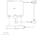
- Fig. 6 shows schematically the apparatus whose operation is depicted in Fig. 5.
- a laser in this case a ring laser used for a ring laser gyro RLG, is powered by a power supply PS which supplies current through an ammeter AM to a cathode CTH.
- the cathode excites the lasing gas, and current passes back to the power supply through a pair of anodes AN.
- Light from the ring laser gyro RLG falls on an intensity monitor IM which sends a signal representing the intensity to an integrated circuit IC.
- the integrated circuit IC also receives a signal from the ammeter AM indicating how much discharge current is being supplied to the cathode CTH.
- the integrated circuit IC may then calculate the noise and send a signal to the power supply PS whenever the noise N approaches the noise service limit NSL or the intensity I approaches the intensity service limit ISL. If the application of the ring laser gyro is such that the noise N may be determined directly at the intensity monitor IM, then the complexity of the integrated circuit IC may be accordingly reduced, or its functions may even be incorporated within the intensity monitor IM.
- the present invention is capable of exploitation in industry, and can be used, whenever it is desired to extend the life of a laser beyond that which is otherwise available. It can be made from elements which considered separate and apart from one another, are entirely conventional, or it can be made from their nonconventional counterparts.
Landscapes
- Physics & Mathematics (AREA)
- Electromagnetism (AREA)
- Engineering & Computer Science (AREA)
- Plasma & Fusion (AREA)
- Optics & Photonics (AREA)
- Lasers (AREA)
Description
- The present invention relates to lasers and has particular relation to extending the life of a laser.
- In a typical laser, and particularly in a ring laser suitable for a ring laser gyroscope or ring laser gyro (RLG), the discharge current fed to the laser is maintained at a constant level. The intensity of the laser gradually fades until laser action no longer occurs. If purity and stability of the frequency of the emitted light is of concern, the noise included within this light will gradually rise. Eventually either the noise N will reach a noise service limit NSL, as shown in Fig. 1, or the intensity I will fall below an intensity service limit ISL as shown in Fig. 2. The laser will fail at a noise time NT, when the noise reaches the noise service limit, or at an intensity time IT, when the intensity reaches the intensity service limit, whichever comes first. The laser must then be replaced, rebuilt with new mirrors and/or new lasing material, or otherwise maintained.
- Regarding the prior art attention is drawn to GB-A-2227 878 which discloses a ring laser gyroscope wherein the intensity of the laser beams is maintained at a constant value. Further attention is drawn to Patent Abstracts of Japan Vol. 9, No. 49, Vol. 6, No.230, and Vol. 12, No. 389.
- In accordance with the present invention a method as set forth in
claim 1 and an apparatus as set forth in claim 5 is provided. Referred embodiments of the invention are disclosed in the dependent claims. - It is an objective of the present invention to extend the life of a laser by maintaining the discharge current at the lowest level necessary to keep the noise below the noise service limit.
- It is a feature of the present invention that the current may be controlled to keep both the noise and the intensity at the appropriate level.
- It is an advantage of the present invention that it greatly extends the usable life of a laser without significantly adding to its cost.
-
- Fig. 1
- is a graphical depiction of prior art operation of an RLG, showing time on the horizontal axis and showing current C, light intensity I, and noise N on the vertical axis; the RLG fails when the noise N reaches the noise service limit NSL at a noise time NT; this is before the intensity I reaches the intensity service limit ISL at an intensity time IT.
- Fig. 2
- is a prior art operating graph similar to Fig. 1, except that the RLG fails when the intensity becomes too low, i.e. NT occurs after IT rather than before it.
- Fig. 3
- graphs the operation of an RLG whereby C is started at the lowest level which will keep I above the ISL, and is gradually increased to maintain I at this level; the RLG fails when N rises above the NSL.
- Fig. 4
- graphs the operation of an embodiment which is a variant of the operation shown in Fig. 3; C is controlled to keep N just below the NSL, and the RLG fails when I falls below the ISL.
- Fig. 5
- graphs the operation of an embodiment combining the best features of Fig. 3 and 4; C is increased whenever either N or I approaches its respective service limit, and the RLG fails only when C reaches the current service limit CSL.
- Fig. 6
- is a schematic diagram of the embodiment, the operation of which is graphed in Fig. 5.
- Fig. 1 shows the operation of typical prior art laser. The current C is held constant, while the noise N gradually rises until it reaches the noise service limit NSL at a noise time NT, at which time the laser is no longer usable. It will, however, continue to emit light at intensity I until the intensity reaches the intensity service limit ISL at an intensity time IT, at which point the laser fails completely.
- Fig. 2 shows an alternative prior art laser operation, in which noise is of a lesser concern than in the laser of Fig. 1. Here IT is less than NT, that is, the laser goes out before noise contamination becomes a serious problem. In either Fig. 1 or Fig. 2, the lifetime of the laser is shorter than desirable.
- Fig. 3 shows the operation of one solution to this problem. Instead of starting both the current and intensity at a reasonably high level, the current is started at a reduced level, just what is needed to keep the intensity above the intensity service limit. As the mirrors and lasing material deteriorate, more and more current is required to maintain this low, constant intensity level. However, high currents, and associated high intensities, are two of the factors which accelerate mirror and material degradation in the first place. Therefore, although the intensity is kept much closer to its service limit, it does not cross it for a much longer period of time.
- The reduced initial current not only brings the initial intensity closer to its service limit, but also brings the initial noise closer to its service limit. However, even though the noise starts at a level higher than that of prior art lasers, it increases much more slowly, because the current and intensity which degrade the mirrors and add to the noise are so much lower. Therefore, the time NT at which the noise crosses the noise service limit is much greater for the Fig. 3 apparatus than it is for either the Fig. 2 or Fig. 1 apparatus.
- It is well known that the intensity I of the laser is a function of the laser's gain G and loss L as follows:

- Similarly, noise N is a function of the gain and loss as follows:

- Finally, the gain G is proportional to the discharge current C:

- Combining these equations, we may obtain the noise N as a function of the discharge current C and the laser intensity I (which are readily measured), and of the design parameters D, E and F (which are known), as follows:

- The laser must be taken out of service and be replaced, or be rebuilt with new mirrors and/or new lasing material, when the indicated noise increases over its service limit.
- Fig. 4 shows the operation of a laser in accordance with the present invention in a variation of the operation shown in Fig. 3. Here, instead of holding the intensity just above its service limit, and allowing the noise to eventually exceed its service limit, the noise is held just below its service limit, while the intensity is allowed to eventually fall below its service limit. Since the current C is being steadily increased to maintain the noise N at a constant level, the intensity I will fall off at a rate slower than that shown in either Fig. 1 or Fig. 2. Thus, although it starts off from a level lower than the level shown in either Fig. 1 or Fig. 2, the intensity time IT, at which the laser fails due to insufficient intensity, is greater than the intensity time IT for either the Fig. 1 or the Fig. 2 apparatus.
- Fig. 5 combines the best features of Fig. 3 and Fig. 4. In the apparatus whose operation is shown in Fig. 5, the current is increased whenever either the noise or the intensity approaches its service limit. In the example shown in Fig. 5, noise growth and intensity decay are made to fluctuate erratically in order to demonstrate the capabilities of this embodiment of the present invention. Thus, the current is increased rapidly during the early portion of the laser's life in order to maintain the noise below the noise service limit. In doing so, the intensity recedes fairly far away from the intensity service limit. Eventually, noise becomes less and less of a problem, and the current is allowed to stabilize at a constant value. This permits the intensity to reapproach its service limit, resulting in the current being raised again, this time pulling back the noise from it service limit. Eventually, the intensity becomes less of a problem, the current settles in at a second plateau, and the noise reapproaches its service limit. This process can be repeated as many times as desired.
- Eventually, in an attempt to work with severely degraded mirrors, the current will rise to such a high level as to reach its own service limit. This current service limit CSL may be imposed by potential damage to the lasing material, limitations in the power supply, or any of a number of other parameters. In general, the laser's failure due to the current C having reached the current service limit CSL at a time CT will occur at a time much later than a failure due to either the noise N and/or the intensity I having reached its respective service limit.
- The intensity, noise, and current service limits are shown herein as being constant, and such will usually be the case. In some applications these limits will vary with time or other parameters, including one another. The principle of using the minimum discharge current needed to meet all appropriate service limits remains unchanged.
- Fig. 6 shows schematically the apparatus whose operation is depicted in Fig. 5. A laser, in this case a ring laser used for a ring laser gyro RLG, is powered by a power supply PS which supplies current through an ammeter AM to a cathode CTH. The cathode excites the lasing gas, and current passes back to the power supply through a pair of anodes AN. Light from the ring laser gyro RLG falls on an intensity monitor IM which sends a signal representing the intensity to an integrated circuit IC. The integrated circuit IC also receives a signal from the ammeter AM indicating how much discharge current is being supplied to the cathode CTH. The integrated circuit IC may then calculate the noise and send a signal to the power supply PS whenever the noise N approaches the noise service limit NSL or the intensity I approaches the intensity service limit ISL. If the application of the ring laser gyro is such that the noise N may be determined directly at the intensity monitor IM, then the complexity of the integrated circuit IC may be accordingly reduced, or its functions may even be incorporated within the intensity monitor IM.
- While particular apparatus for determining the discharge current, intensity, and noise have been shown, it is apparent that any convenient apparatus performing these functions may be used.
- The present invention is capable of exploitation in industry, and can be used, whenever it is desired to extend the life of a laser beyond that which is otherwise available. It can be made from elements which considered separate and apart from one another, are entirely conventional, or it can be made from their nonconventional counterparts.
- While particular embodiments of the present invention have been described above, the scope of the present invention is not limited thereto, but is limited only by the following claims.
Claims (8)
- A method for extending a life of a laser, comprising the steps of:(a) measuring an intensity (I) of the laser;(b) measuring a magnitude of a discharge current (C) applied to the laser;(c) using the intensity (I) of the laser and the magnitude of the discharge current to calculate a noise magnitude (N);(d) comparing the noise magnitude (N) with a pre-established noise service limit (NSL); and(e) increasing the discharge current (C) applied to the laser when the noise magnitude (N) rises above the noise service limit (NSL), until the noise magnitude (N) falls below the noise service limit (NSL).
- The method for extending a life of a laser as claimed in claim 1, comprising the further steps of:(f) comparing the intensity of the laser with a pre-established intensity service limit (ISL); and(g) increasing the discharge current (C) applied to the laser when the intensity (I) of the laser falls below the intensity service limit (ISL), until the intensity (I) of the laser rises above the intensity service limit (ISL).
- The method of any of claims 1 or 2, wherein the step of using the intensity (I) of the laser and the magnitude of the discharge current (C) to calculate the noise magnitude (N) comprises the step of calculating:

- The method of any of Claims 1-3, wherein the laser is a ring laser.
- An apparatus for extending a life of a laser, comprising;(a) means for measuring an intensity (I) of the laser;(b) means for measuring a magnitude of a discharge current (C) applied to the laser;(c) means for using the intensity (I) of the laser and the magnitude of the discharge current (C) to calculate a noise magnitude (N);(d) means for comparing the noise magnitude (N) with a pre-established noise service limit (NSL); and(e) means for increasing the discharge current (C) applied to the laser when the noise magnitude (N) rises above the noise service limit (NSL), until the noise magnitude (N) falls below the noise service limit (NSL).
- The apparatus for extending a life of a laser of claim 5, further comprising:(f) means for comparing the intensity (I) of the laser with a pre-established intensity service limit (ISL); and(g) means for increasing the discharge current (C) applied to the laser when the intensity (I) of the laser falls below the intensity service limit (ISL), until the intensity (I) of the laser rises above the intensity service limit (ISL).
- The apparatus of any of Claims 5 or 6, wherein the means for using the intensity (I) of the laser and the magnitude of the discharge current (C) to calculate the noise magnitude (N) comprises means for calculating:

- The apparatus of any of Claims 5-7, wherein the laser is a ring laser.
Applications Claiming Priority (2)
| Application Number | Priority Date | Filing Date | Title |
|---|---|---|---|
| US764872 | 1991-09-24 | ||
| US07/764,872 US5199037A (en) | 1991-09-24 | 1991-09-24 | Extended laser life |
Publications (2)
| Publication Number | Publication Date |
|---|---|
| EP0543110A1 EP0543110A1 (en) | 1993-05-26 |
| EP0543110B1 true EP0543110B1 (en) | 1996-05-08 |
Family
ID=25072031
Family Applications (1)
| Application Number | Title | Priority Date | Filing Date |
|---|---|---|---|
| EP92116185A Expired - Lifetime EP0543110B1 (en) | 1991-09-24 | 1992-09-22 | Extended laser life |
Country Status (4)
| Country | Link |
|---|---|
| US (1) | US5199037A (en) |
| EP (1) | EP0543110B1 (en) |
| JP (1) | JPH06216443A (en) |
| DE (1) | DE69210550T2 (en) |
Families Citing this family (2)
| Publication number | Priority date | Publication date | Assignee | Title |
|---|---|---|---|---|
| US5552590A (en) * | 1992-09-08 | 1996-09-03 | Nippondenso Co., Ltd. | Optical information reading apparatus having means for judging laser deterioration |
| US20060159140A1 (en) * | 2005-01-17 | 2006-07-20 | Fanuc Ltd | Laser oscillator and method of estimating the lifetime of a pump light source |
Family Cites Families (3)
| Publication number | Priority date | Publication date | Assignee | Title |
|---|---|---|---|---|
| US4856008A (en) * | 1987-12-29 | 1989-08-08 | Ricoh Company, Ltd. | Semiconductor laser control apparatus |
| GB2227878B (en) * | 1989-02-03 | 1992-04-22 | Ferranti Int Signal | Ring laser gyroscope |
| US5128950A (en) * | 1989-08-02 | 1992-07-07 | Hamamatsu Photonics K.K. | Low noise pulsed light source using laser diode |
-
1991
- 1991-09-24 US US07/764,872 patent/US5199037A/en not_active Expired - Lifetime
-
1992
- 1992-08-11 JP JP4214050A patent/JPH06216443A/en not_active Withdrawn
- 1992-09-22 EP EP92116185A patent/EP0543110B1/en not_active Expired - Lifetime
- 1992-09-22 DE DE69210550T patent/DE69210550T2/en not_active Expired - Fee Related
Also Published As
| Publication number | Publication date |
|---|---|
| US5199037A (en) | 1993-03-30 |
| EP0543110A1 (en) | 1993-05-26 |
| JPH06216443A (en) | 1994-08-05 |
| DE69210550D1 (en) | 1996-06-13 |
| DE69210550T2 (en) | 1996-12-19 |
Similar Documents
| Publication | Publication Date | Title |
|---|---|---|
| US6584127B2 (en) | Light emitting device | |
| US5440578A (en) | Gas replenishment method and apparatus for excimer lasers | |
| US4977573A (en) | Excimer laser output control device | |
| KR0148521B1 (en) | Excimer laser device | |
| US6212214B1 (en) | Performance control system and method for gas discharge lasers | |
| US6526085B2 (en) | Performance control system and method for gas discharge lasers | |
| EP0543110A1 (en) | Extended laser life | |
| JP4274244B2 (en) | Laser diode pumped solid state laser oscillator and laser diode control method in the oscillator | |
| US6330267B1 (en) | Performance control system and method for gas discharge lasers | |
| EP0342981A1 (en) | Laser | |
| JP2929992B2 (en) | Optical transmission circuit | |
| JP2004259751A (en) | Ld-pumped solid-state laser system and its operating method | |
| US5164953A (en) | Population inversion by excited energy level absorption | |
| JP2542821B2 (en) | Laser processing equipment | |
| US20040009620A1 (en) | Excimer laser apparatus | |
| US5274658A (en) | Population inversion by excited energy level absorption | |
| KR100250394B1 (en) | Gas replenishment method and apparatus for excimer lasers | |
| JPS61133681A (en) | Monitor of light-output controlling device of gas laser | |
| US4340968A (en) | Rare-gas hydrogen-halide excimer laser with hydrogen additive | |
| JP2000151002A (en) | Gas discharge laser performance control method | |
| Mizeraczyk et al. | The performance of the hollow-cathode discharge continuous-wave multicolour He-Cd+ laser | |
| JP4470621B2 (en) | X-ray generator | |
| JPH11274628A (en) | Semiconductor laser driver | |
| JP2002319734A (en) | Laser light source device | |
| JPH11162221A (en) | ASE light source device |
Legal Events
| Date | Code | Title | Description |
|---|---|---|---|
| PUAI | Public reference made under article 153(3) epc to a published international application that has entered the european phase |
Free format text: ORIGINAL CODE: 0009012 |
|
| AK | Designated contracting states |
Kind code of ref document: A1 Designated state(s): DE FR GB |
|
| 17P | Request for examination filed |
Effective date: 19931125 |
|
| 17Q | First examination report despatched |
Effective date: 19940607 |
|
| GRAH | Despatch of communication of intention to grant a patent |
Free format text: ORIGINAL CODE: EPIDOS IGRA |
|
| GRAA | (expected) grant |
Free format text: ORIGINAL CODE: 0009210 |
|
| AK | Designated contracting states |
Kind code of ref document: B1 Designated state(s): DE FR GB |
|
| ET | Fr: translation filed | ||
| REF | Corresponds to: |
Ref document number: 69210550 Country of ref document: DE Date of ref document: 19960613 |
|
| PLBE | No opposition filed within time limit |
Free format text: ORIGINAL CODE: 0009261 |
|
| 26N | No opposition filed | ||
| REG | Reference to a national code |
Ref country code: GB Ref legal event code: IF02 |
|
| PGFP | Annual fee paid to national office [announced via postgrant information from national office to epo] |
Ref country code: FR Payment date: 20080917 Year of fee payment: 17 |
|
| PGFP | Annual fee paid to national office [announced via postgrant information from national office to epo] |
Ref country code: GB Payment date: 20080929 Year of fee payment: 17 |
|
| PGFP | Annual fee paid to national office [announced via postgrant information from national office to epo] |
Ref country code: DE Payment date: 20081031 Year of fee payment: 17 |
|
| GBPC | Gb: european patent ceased through non-payment of renewal fee |
Effective date: 20090922 |
|
| REG | Reference to a national code |
Ref country code: FR Ref legal event code: ST Effective date: 20100531 |
|
| PG25 | Lapsed in a contracting state [announced via postgrant information from national office to epo] |
Ref country code: FR Free format text: LAPSE BECAUSE OF NON-PAYMENT OF DUE FEES Effective date: 20090930 Ref country code: DE Free format text: LAPSE BECAUSE OF NON-PAYMENT OF DUE FEES Effective date: 20100401 |
|
| PG25 | Lapsed in a contracting state [announced via postgrant information from national office to epo] |
Ref country code: GB Free format text: LAPSE BECAUSE OF NON-PAYMENT OF DUE FEES Effective date: 20090922 |