EP0542547A1 - Fuel tank filter - Google Patents
Fuel tank filter Download PDFInfo
- Publication number
- EP0542547A1 EP0542547A1 EP92310345A EP92310345A EP0542547A1 EP 0542547 A1 EP0542547 A1 EP 0542547A1 EP 92310345 A EP92310345 A EP 92310345A EP 92310345 A EP92310345 A EP 92310345A EP 0542547 A1 EP0542547 A1 EP 0542547A1
- Authority
- EP
- European Patent Office
- Prior art keywords
- fuel tank
- envelope
- spring
- filter
- fuel
- Prior art date
- Legal status (The legal status is an assumption and is not a legal conclusion. Google has not performed a legal analysis and makes no representation as to the accuracy of the status listed.)
- Granted
Links
Images

Classifications
-
- B—PERFORMING OPERATIONS; TRANSPORTING
- B01—PHYSICAL OR CHEMICAL PROCESSES OR APPARATUS IN GENERAL
- B01D—SEPARATION
- B01D29/00—Filters with filtering elements stationary during filtration, e.g. pressure or suction filters, not covered by groups B01D24/00 - B01D27/00; Filtering elements therefor
- B01D29/11—Filters with filtering elements stationary during filtration, e.g. pressure or suction filters, not covered by groups B01D24/00 - B01D27/00; Filtering elements therefor with bag, cage, hose, tube, sleeve or like filtering elements
- B01D29/13—Supported filter elements
- B01D29/15—Supported filter elements arranged for inward flow filtration
-
- B—PERFORMING OPERATIONS; TRANSPORTING
- B01—PHYSICAL OR CHEMICAL PROCESSES OR APPARATUS IN GENERAL
- B01D—SEPARATION
- B01D35/00—Filtering devices having features not specifically covered by groups B01D24/00 - B01D33/00, or for applications not specifically covered by groups B01D24/00 - B01D33/00; Auxiliary devices for filtration; Filter housing constructions
- B01D35/02—Filters adapted for location in special places, e.g. pipe-lines, pumps, stop-cocks
- B01D35/027—Filters adapted for location in special places, e.g. pipe-lines, pumps, stop-cocks rigidly mounted in or on tanks or reservoirs
- B01D35/0273—Filtering elements with a horizontal or inclined rotation or symmetry axis submerged in tanks or reservoirs
-
- B—PERFORMING OPERATIONS; TRANSPORTING
- B01—PHYSICAL OR CHEMICAL PROCESSES OR APPARATUS IN GENERAL
- B01D—SEPARATION
- B01D35/00—Filtering devices having features not specifically covered by groups B01D24/00 - B01D33/00, or for applications not specifically covered by groups B01D24/00 - B01D33/00; Auxiliary devices for filtration; Filter housing constructions
- B01D35/26—Filters with built-in pumps filters provided with a pump mounted in or on the casing
-
- F—MECHANICAL ENGINEERING; LIGHTING; HEATING; WEAPONS; BLASTING
- F02—COMBUSTION ENGINES; HOT-GAS OR COMBUSTION-PRODUCT ENGINE PLANTS
- F02M—SUPPLYING COMBUSTION ENGINES IN GENERAL WITH COMBUSTIBLE MIXTURES OR CONSTITUENTS THEREOF
- F02M37/00—Apparatus or systems for feeding liquid fuel from storage containers to carburettors or fuel-injection apparatus; Arrangements for purifying liquid fuel specially adapted for, or arranged on, internal-combustion engines
- F02M37/22—Arrangements for purifying liquid fuel specially adapted for, or arranged on, internal-combustion engines, e.g. arrangements in the feeding system
- F02M37/32—Arrangements for purifying liquid fuel specially adapted for, or arranged on, internal-combustion engines, e.g. arrangements in the feeding system characterised by filters or filter arrangements
- F02M37/50—Filters arranged in or on fuel tanks
-
- B—PERFORMING OPERATIONS; TRANSPORTING
- B01—PHYSICAL OR CHEMICAL PROCESSES OR APPARATUS IN GENERAL
- B01D—SEPARATION
- B01D2201/00—Details relating to filtering apparatus
- B01D2201/04—Supports for the filtering elements
- B01D2201/0461—Springs
Definitions
- the present invention relates to improved fuel tank filters, and more particularly to filters for use in a fuel tank where the fuel pump is housed inside the fuel tank and the fuel level occasionally falls below the bottom of the fuel pump.
- the pump is typically fixed to the top of the tank to simplify sealing holes in the tank through which connections to fuel lines, electrical power and control wires, and the like are made for the fuel pump.
- the fuel pump inlet and filter thereon remain submerged at the bottom of the fuel tank.
- the pump is typically designed to have a bottom inlet about 1.27 cm above the bottom of the tank.
- the rigidity of the metal tank assures that the 1.27 cm spacing changes very little.
- the filters are designed to provide a "wicking" action so that vapor will not enter the fuel pump inlet at infrequent times when the fuel level drops below the bottom of the pump inlet, such as during vehicle turning, stopping, or hill climbing maneuvers.
- filters biased toward the fuel tank botton also have developed a problem due to friction at the contact points on the filter that are between the separating means and tank bottom from typical motor vehicle vibrations. This friction results in excessive wear on the filter with a concomitant decrease in filtration efficiency, and may also jeopardize the integrity of the filter material.
- a fuel tank filter including filter material forming an envelope, a wire spring located within the envelope attached to the pump inlet and configured such that it separates the envelope layers and biases one side of the envelope toward the bottom of the tank, and a rib on the envelope interior to provide a bearing surface for the spring as it biases the envelope.
- the wire spring is of a z-shaped bilaterally symmetric configuration dimensioned to prevent collapse of the envelope during normal fuel pump usage.
- the wire spring is of a conical helical design centered about the fuel pump inlet.
- the fuel tank filters of the present invention reliably accommodate the relative movement of the fuel tank bottom over prolonged periods of exposure to alcohol-blended gasolines, thereby assuring the presence of liquid fuel at the pump inlet.
- FIG. 1 is a perspective view of a fuel filter of one embodiment of the present invention, partly broken away.
- FIG. 2 is a cross-sectional view taken along line 2-2 of FIG. 1.
- FIG. 3 is a partial top-plan view taken along line 3-3 of FIG. 2.
- FIG. 4 is an exploded cross-sectional view of the connector of FIG. 3 taken along line 4-4 of FIG. 3.
- FIG. 5 is a cross-sectional view taken along line 5-5 of FIG. 3.
- FIG. 6 is a cross-sectional view taken along line 6-6 of FIG. 3.
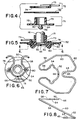
- FIG. 7 is a top plan view of the spring of FIGs. 1 and 2.
- FIG. 8 is a side view of the spring of FIG. 7.
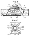
- FIG. 9 is a cross-sectional view like FIG. 2 of another embodiment of the filter of the present invention.
- FIG. 10 is a cross-sectional view of the connector of FIG. 9 taken along line 9-9 of FIG. 10.
- the filter 20 of the present invention is for use in a fuel tank 10. Also enclosed in the fuel tank 10 is a fuel pump inlet 16, and a fuel pump connected by wires, fuel lines, and bracketed to the top of tank 10 (all of which are conventional and none of which are shown). As discussed above, the present invention is designed for occasions where the bottom 14 of fuel tank 10, for one reason or another, moves up and down with respect to fuel pump inlet 16. As previously discussed, this commonly occurs when fuel tank 10 is comprised of plastic or some other material with a relatively high coefficient of expansion, and a pump is fixed to the top of fuel tank 10.
- filter 20 attaches to inlet 16 and includes a filtration material envelope 30, a generally double z-shaped spring 50, and a plastic connector element 70.
- the spring 50 separates the walls of envelope 30, and thereby holds envelope 30 open to improve fuel flow through the envelope 30, and biases the bottom of envelope 30 toward tank bottom 14.
- the envelope 30 is preferably composed of a nylon screen material 32.
- the screen material 32 is welded closed by latitudinal welds 34, 36 and longitudinal weld 38 to form the envelope shape.
- Connector 70 is preferably of a two-piece construction, and is sealed to envelope 30 by the placement of filter screen 32 between top element 72 and bottom element 76 at top shoulder 74 and bottom shoulder 78.
- Integral with top shoulder 74 is reference flange 75 dimensioned to slide into a reference slot on a member (which is conventional and not shown) affixed either to the fuel pump or inlet 16 to secure filter 20 to inlet 16.
- Top shoulder 74 is also provided with reference slots 77, spaced 90° apart, for engagement with a pin or tang (which is conventional and not shown) extending from the bottom of the fuel pump to further align filter 20.
- a hole may be placed in flange 75 to allow a similar pin to be used to secure filter 20 to the pump by means of a conventional fastener, such as a lock washer and nut, located at the end of the pin.
- a conventional fastener such as a lock washer and nut
- Integral with bottom shoulder 78 are diametrically opposed positioning plugs 80, each with retaining ridges 82 extending outwardly from the plug surface to define channels 84.
- fitting 73 integral with bottom shoulder 78 and dimensioned to tightly fit about the outer diameter of inlet 16 is fitting 73. Heat-staked to the end of fitting 73 is swell band 71, preferably of stainless steel, to assure a snug fit between inlet 16 and fitting 73.
- a spring 50 is located within envelope 30, and is best seen in FIGs. 7 and 8.
- the spring 50 has a bilateral symmetric and is preferably in a double z-shaped configuration in the static state when viewed from a plane normal to the top and base legs.
- the spring is composed of a continuous piece of wire with top legs comprised of top runs 52 of a radius greater than the inner radius of fitting 72, positioning runs 54 of a radius to snap fit into channels 84, and clearance runs 56 extending beyond bottom shoulder 78; side legs comprised of outward runs 58, runs 60 parallel to the spring axis of symmetric and inward runs 62; and base legs comprised of inward runs 64 with hairpin curve 65.
- Spring 50 is located on connector 70 by snap fitting the positioning runs 54 around the positioning plugs 80 in channels 84 and thus the top leg of spring 50 bears against bottom shoulder 78 of bottom element 76.
- Screen material 32 is preferably secured between shoulders 74, 78, and top and bottom elements 72, 76 are preferably secured together, by sonic welding.
- Screen material 32 is wrapped around the joints between the top and side legs of spring 50 and meets other screen material at welds 34, 36, and 38, all preferably sonically welded, to form envelope 30.
- wear pad 90 Located inside of envelope 30 is wear pad 90, which is affixed to filter material 32, preferably by sonic welding, at a point that prevents spring 50 from contacting filter material 32.
- wear pad 90 is located at about mid-length along inward runs 64 of the base leg of spring 50.
- the spring 50 is preferably in a z-shaped configuration in its static state, and will tend to pull the filter 20 into the shape shown in FIG. 2.
- tank bottom 14 interacts with spring 50 via wear pad 90 and pushes up on filter 20, causing the side leg of spring 50 to become more parallel with tank bottom 14 so that the filter 20 takes the shape shown in phantom in FIG. 2.
- the base leg of spring 50 advances on wear pad 90, yet fails to contact filter material 32 thereby avoiding direct sliding by spring 50 on filter screen 32 which affects filtration efficiency or may jeopardize filter integrity.
- spring 50 pushes the filter assembly via wear pad 90 back into its original position, which holds the filter material envelope 30 further toward the bottom 14 of fuel tank 10 by way of sliding against wear pad 90.
- spring 50 is a continuous 1.5 mm stainless steel spring wire with wire ends soldered at joint 66.
- Top run 52 has an inner radius of 8.6 mm
- positioning run 54 has a diameter of 3.9 mm
- clearance run 56 has a length of approximately 20 mm from the center of the positioning run, and the clearance runs are spaced 10 mm apart.
- the top leg and base leg are spaced 29 mm apart vertically, and the side leg of spring 50 extends a horizontal distance of 55 mm.
- Inward run 64 extends horizontally approximately 16 mm, with a hairpin curve 65 of 3.5 mm radius.
- the preferred screen 32 is of nylon and has a 180 x 38 mesh, and is capable of removing impurities 60 microns or larger.
- Connector 70 and wear plate 90 are preferably made from molded plastic, such as acetal resin, though they may also be made from nylon.
- Top element 72 and bottom element 76 are preferably secured together and sealed around screen material 32 by sonic welding.
- Wear plate 90 is also secured to screen material 32 by sonic welding.
- a filter 120 of a second embodiment of the invention is shown in FIGS. 9 and 10.
- the filter 120 is generally constructed similar to filter 20, and thus for the most part it has the same elements as filter 20 and therefore the elements of the two embodiments are numbered with the same last two digits.
- Spring 150 is a conical helical compression spring with the smaller end positioned and bearing against connector 170 on bottom shoulder 178 and the larger end positioned to interact with filter envelope 130.
- Connector 170 is of the same general configuration as connector 70 except that integral with bottom shoulder 178 are positioning plugs 180, spaced 120° apart, each provided with retaining ridges 182 defining channels 184 of sufficient depth to accommodate the diameter of one turn of spring 150, and thus retain the spring 150 to the connector 170.
- Filter 120 is similarly constructed as filter 20, but wear pad 190 located in the interior of envelope 130 on screen material 132 is a circular configuration with L-shaped cross-section and having vertical leg 192 inside the diameter of the spring, thereby horizontally positioning spring 150, and horizontal leg 194, extending outwardly and under the last turn of spring 150, thereby providing a bearing surface for the free end of spring 150.
- spring 150 is composed of 1.5 mm stainless steel spring wire with approximately 4.5 turns and a free length of approximately 29 mm and a top outside diameter of approximately 30 mm and a bottom outside diameter sufficient to enable each turn to collapse within a succeeding turn, which may be readily determined by those skilled in the art.
- the top and bottom ends of spring 150 are also preferably squared and ground.
- Wear pad 190 is preferably composed of the same plastic as connector 170 and is affixed to screen material 132 by sonic welding.
- the apparatus of the present invention is capable of being incorporated in the form of a variety of embodiments, only a few of which have been illustrated and described above.
- the invention may be embodied in other forms without departing from its spirit or essential characteristics.
- other spring materials may be used, including other cross-sectional shapes of spring steel, and other securing means between springs 50 or 150, and connectors 70 or 170, respectively, may be implemented including imbedding the spring into the bottom of the shoulder 78.
- the wear pad 192 may be segmented instead of a continuous circle.
Landscapes
- Chemical & Material Sciences (AREA)
- Chemical Kinetics & Catalysis (AREA)
- Engineering & Computer Science (AREA)
- Combustion & Propulsion (AREA)
- Mechanical Engineering (AREA)
- General Engineering & Computer Science (AREA)
- Cooling, Air Intake And Gas Exhaust, And Fuel Tank Arrangements In Propulsion Units (AREA)
- Filtration Of Liquid (AREA)
- Details Of Rigid Or Semi-Rigid Containers (AREA)
- Fuel-Injection Apparatus (AREA)
Abstract
Description
- The present invention relates to improved fuel tank filters, and more particularly to filters for use in a fuel tank where the fuel pump is housed inside the fuel tank and the fuel level occasionally falls below the bottom of the fuel pump.
- With the introduction of motor vehicles with fuel injected engines, it has become necessary to locate fuel pumps inside fuel tanks. Because the fuel system is a closed system, the pump is typically fixed to the top of the tank to simplify sealing holes in the tank through which connections to fuel lines, electrical power and control wires, and the like are made for the fuel pump.
- At present, with metal fuel tanks, the fuel pump inlet and filter thereon remain submerged at the bottom of the fuel tank. The pump is typically designed to have a bottom inlet about 1.27 cm above the bottom of the tank. The rigidity of the metal tank assures that the 1.27 cm spacing changes very little. Moreover, the filters are designed to provide a "wicking" action so that vapor will not enter the fuel pump inlet at infrequent times when the fuel level drops below the bottom of the pump inlet, such as during vehicle turning, stopping, or hill climbing maneuvers.
- There is a current desire to change from metal fuel tanks to plastic fuel tanks, however. These tanks are less rigid, and due to thermal contraction or expansion, the distance between the top and bottom of the tanks is known to vary by as much as 2.54 cm. Due to the typical fixture of the pump to the top of the fuel tank, an increase of 2.54 cm in the distance between the top and bottom of the tank results in the bottom of the fuel pump inlet sometimes being more than 2.54 cm from the bottom of the tank. If the fuel depth in the tank is low at the same time the tank has expanded, the bottom of the fuel pump inlet may be too far above the level of the fuel for even the wicking action of the filter material to provide liquid fuel to the pump inlet.
- The fact that the bottom of the tank moves up and down, coupled with the requirement that liquid fuel always be available at the pump inlet, presents a problem. One attempted solution to this problem has been to use a fuel tank filter with an envelope of filtration material and an internal plastic separator. The separator is flexible, and biased so that it holds the filter envelope on the bottom of the tank. While this concept appears sound, the filters manufactured according to this design have not solved the problem. Specifically, tests conducted in developing the present invention show that the plastic used to construct the separator loses its flexibility after exposure to gasoline containing alcohol.
- This problem has been solved for some filter designs by a separator which incorporates a metal leaf spring that biases the separator and holds the envelope toward the bottom of the fuel tank, which is described in U.S. Patent No. 5,049,271 and is incorporated herein by reference. It can be appreciated that this construction may not serve for all filter designs.
- Moreover, filters biased toward the fuel tank botton also have developed a problem due to friction at the contact points on the filter that are between the separating means and tank bottom from typical motor vehicle vibrations. This friction results in excessive wear on the filter with a concomitant decrease in filtration efficiency, and may also jeopardize the integrity of the filter material.
- It has now been found that certain of the foregoing problems are overcome by the provision of a fuel tank filter including filter material forming an envelope, a wire spring located within the envelope attached to the pump inlet and configured such that it separates the envelope layers and biases one side of the envelope toward the bottom of the tank, and a rib on the envelope interior to provide a bearing surface for the spring as it biases the envelope.
- In one embodiment thereof, the wire spring is of a z-shaped bilaterally symmetric configuration dimensioned to prevent collapse of the envelope during normal fuel pump usage. Alternatively, in another embodiment, the wire spring is of a conical helical design centered about the fuel pump inlet.
- The fuel tank filters of the present invention reliably accommodate the relative movement of the fuel tank bottom over prolonged periods of exposure to alcohol-blended gasolines, thereby assuring the presence of liquid fuel at the pump inlet.
- The foregoing features and advantages of this invention will be further understood upon consideration of the following detailed description of embodiments of the invention taken in conjunction with the accompanying drawings, in which:
-
- FIG. 1 is a perspective view of a fuel filter of one embodiment of the present invention, partly broken away.
- FIG. 2 is a cross-sectional view taken along line 2-2 of FIG. 1.
- FIG. 3 is a partial top-plan view taken along line 3-3 of FIG. 2.
- FIG. 4 is an exploded cross-sectional view of the connector of FIG. 3 taken along line 4-4 of FIG. 3.
- FIG. 5 is a cross-sectional view taken along line 5-5 of FIG. 3.
- FIG. 6 is a cross-sectional view taken along line 6-6 of FIG. 3.
- FIG. 7 is a top plan view of the spring of FIGs. 1 and 2.
- FIG. 8 is a side view of the spring of FIG. 7.
- FIG. 9 is a cross-sectional view like FIG. 2 of another embodiment of the filter of the present invention.
- FIG. 10 is a cross-sectional view of the connector of FIG. 9 taken along line 9-9 of FIG. 10.
- As shown in FIGS. 1 and 2, the filter 20 of the present invention is for use in a
fuel tank 10. Also enclosed in thefuel tank 10 is afuel pump inlet 16, and a fuel pump connected by wires, fuel lines, and bracketed to the top of tank 10 (all of which are conventional and none of which are shown). As discussed above, the present invention is designed for occasions where thebottom 14 offuel tank 10, for one reason or another, moves up and down with respect tofuel pump inlet 16. As previously discussed, this commonly occurs whenfuel tank 10 is comprised of plastic or some other material with a relatively high coefficient of expansion, and a pump is fixed to the top offuel tank 10. - As shown in FIG. 1, filter 20 attaches to
inlet 16 and includes afiltration material envelope 30, a generally double z-shaped spring 50, and aplastic connector element 70. Thespring 50 separates the walls ofenvelope 30, and thereby holdsenvelope 30 open to improve fuel flow through theenvelope 30, and biases the bottom ofenvelope 30 towardtank bottom 14. Theenvelope 30 is preferably composed of anylon screen material 32. Thescreen material 32 is welded closed bylatitudinal welds longitudinal weld 38 to form the envelope shape. -
Connector 70, as shown in FIGs. 3-6, is preferably of a two-piece construction, and is sealed toenvelope 30 by the placement offilter screen 32 betweentop element 72 andbottom element 76 attop shoulder 74 andbottom shoulder 78. Integral withtop shoulder 74 isreference flange 75 dimensioned to slide into a reference slot on a member (which is conventional and not shown) affixed either to the fuel pump orinlet 16 to secure filter 20 toinlet 16.Top shoulder 74 is also provided withreference slots 77, spaced 90° apart, for engagement with a pin or tang (which is conventional and not shown) extending from the bottom of the fuel pump to further align filter 20. Also, a hole may be placed inflange 75 to allow a similar pin to be used to secure filter 20 to the pump by means of a conventional fastener, such as a lock washer and nut, located at the end of the pin. Integral withbottom shoulder 78 are diametrically opposedpositioning plugs 80, each withretaining ridges 82 extending outwardly from the plug surface to definechannels 84. Also integral withbottom shoulder 78 and dimensioned to tightly fit about the outer diameter ofinlet 16 is fitting 73. Heat-staked to the end of fitting 73 isswell band 71, preferably of stainless steel, to assure a snug fit betweeninlet 16 and fitting 73. - A
spring 50 is located withinenvelope 30, and is best seen in FIGs. 7 and 8. Thespring 50 has a bilateral symmetric and is preferably in a double z-shaped configuration in the static state when viewed from a plane normal to the top and base legs. In the preferred embodiment, the spring is composed of a continuous piece of wire with top legs comprised oftop runs 52 of a radius greater than the inner radius offitting 72, positioning runs 54 of a radius to snap fit intochannels 84, and clearance runs 56 extending beyondbottom shoulder 78; side legs comprised ofoutward runs 58, runs 60 parallel to the spring axis of symmetric andinward runs 62; and base legs comprised ofinward runs 64 withhairpin curve 65. -
Spring 50 is located onconnector 70 by snap fitting the positioning runs 54 around thepositioning plugs 80 inchannels 84 and thus the top leg ofspring 50 bears againstbottom shoulder 78 ofbottom element 76.Screen material 32 is preferably secured betweenshoulders bottom elements Screen material 32 is wrapped around the joints between the top and side legs ofspring 50 and meets other screen material atwelds envelope 30. - Located inside of
envelope 30 is wearpad 90, which is affixed tofilter material 32, preferably by sonic welding, at a point that preventsspring 50 from contactingfilter material 32. In the preferred embodiment,wear pad 90 is located at about mid-length alonginward runs 64 of the base leg ofspring 50. - The
spring 50 is preferably in a z-shaped configuration in its static state, and will tend to pull the filter 20 into the shape shown in FIG. 2. When thefuel tank bottom 14 alters its height, as depicted in phantom lines in FIG. 2,tank bottom 14 interacts withspring 50 viawear pad 90 and pushes up on filter 20, causing the side leg ofspring 50 to become more parallel withtank bottom 14 so that the filter 20 takes the shape shown in phantom in FIG. 2. It is also to be noted that the base leg ofspring 50 advances onwear pad 90, yet fails to contactfilter material 32 thereby avoiding direct sliding byspring 50 onfilter screen 32 which affects filtration efficiency or may jeopardize filter integrity. When the tank bottom 14 drops,spring 50 pushes the filter assembly viawear pad 90 back into its original position, which holds thefilter material envelope 30 further toward the bottom 14 offuel tank 10 by way of sliding againstwear pad 90. - In the preferred embodiment,
spring 50 is a continuous 1.5 mm stainless steel spring wire with wire ends soldered at joint 66.Top run 52 has an inner radius of 8.6 mm, positioningrun 54 has a diameter of 3.9 mm andclearance run 56 has a length of approximately 20 mm from the center of the positioning run, and the clearance runs are spaced 10 mm apart. The top leg and base leg are spaced 29 mm apart vertically, and the side leg ofspring 50 extends a horizontal distance of 55 mm.Inward run 64 extends horizontally approximately 16 mm, with ahairpin curve 65 of 3.5 mm radius. Thepreferred screen 32 is of nylon and has a 180 x 38 mesh, and is capable of removingimpurities 60 microns or larger.Connector 70 and wearplate 90 are preferably made from molded plastic, such as acetal resin, though they may also be made from nylon.Top element 72 andbottom element 76 are preferably secured together and sealed aroundscreen material 32 by sonic welding.Wear plate 90 is also secured to screenmaterial 32 by sonic welding. - A filter 120 of a second embodiment of the invention is shown in FIGS. 9 and 10. The filter 120 is generally constructed similar to filter 20, and thus for the most part it has the same elements as filter 20 and therefore the elements of the two embodiments are numbered with the same last two digits.
- There are, however, several differences.
Spring 150 is a conical helical compression spring with the smaller end positioned and bearing againstconnector 170 onbottom shoulder 178 and the larger end positioned to interact withfilter envelope 130.Connector 170 is of the same general configuration asconnector 70 except that integral withbottom shoulder 178 are positioningplugs 180, spaced 120° apart, each provided with retainingridges 182 definingchannels 184 of sufficient depth to accommodate the diameter of one turn ofspring 150, and thus retain thespring 150 to theconnector 170. - Filter 120 is similarly constructed as filter 20, but wear
pad 190 located in the interior ofenvelope 130 onscreen material 132 is a circular configuration with L-shaped cross-section and havingvertical leg 192 inside the diameter of the spring, thereby horizontally positioningspring 150, andhorizontal leg 194, extending outwardly and under the last turn ofspring 150, thereby providing a bearing surface for the free end ofspring 150. - When the
fuel tank bottom 114 alters its height, as depicted in phantom lines on FIG. 9,helical spring 150 collapses on itself so that filter 120 takes the shape shown in phantom in FIG. 9.Wear pad 190 again functions to prevent wear onfilter material 132 which affects filtration efficiency or may jeopardize filter integrity. Whentank bottom 114 drops,spring 150 pushes the filter assembly viawear pad 190 back into its original position, which holds thefilter material envelope 130 further toward the bottom 114 by way of sliding againstwear pad 190horizontal leg 194. - In the preferred embodiment of this configuration,
spring 150 is composed of 1.5 mm stainless steel spring wire with approximately 4.5 turns and a free length of approximately 29 mm and a top outside diameter of approximately 30 mm and a bottom outside diameter sufficient to enable each turn to collapse within a succeeding turn, which may be readily determined by those skilled in the art. The top and bottom ends ofspring 150 are also preferably squared and ground.Wear pad 190 is preferably composed of the same plastic asconnector 170 and is affixed toscreen material 132 by sonic welding. - It should be appreciated that the apparatus of the present invention is capable of being incorporated in the form of a variety of embodiments, only a few of which have been illustrated and described above. The invention may be embodied in other forms without departing from its spirit or essential characteristics. For example, other spring materials may be used, including other cross-sectional shapes of spring steel, and other securing means between
springs connectors shoulder 78. Thewear pad 192 may be segmented instead of a continuous circle. The described embodiments are to be considered in all respects only as illustrative and not restrictive and the scope of the invention is, therefore, indicated by the appended claims rather than by the foregoing description. Thus, while the invention has been described with reference to particular embodiments, modifications of structure, materials and the like would be apparent to those skilled in the art, yet still fall within the scope of the invention.
Claims (20)
- A fuel tank filter connectable to the inlet of a fuel pump mounted inside a fuel tank comprising:
filtration material forming an envelope; and
a metal spring inside said envelope and attached to said inlet in a manner such that the spring separates the walls of said envelope and biases the envelope towards the bottom of the fuel tank. - The fuel tank filter of claim 1 further comprising a connector with said filtration envelope molded into said connector, said spring mounted on said connector, and said connector mounted on the fuel pump inlet thereby attaching said filter to said inlet.
- The fuel tank filter of claim 2 wherein said connector is imbedded to said spring at an end thereof.
- The fuel tank filter as in any one of claims 1-3, further comprising a wear pad affixed to said filtration material and slideably engaging the free end of said spring thereby preventing contact between the spring and filtration material.
- The fuel tank filter of claim 2 wherein the spring comprises stainless steel wire in a generally double Z-shaped configuration, with the top legs thereof snap-fitting onto said connector, side legs extending downwardly and outwardly therefrom and converging inwardly toward the bottom legs, which converge inwardly and join at a curve extending toward the inlet.
- The fuel tank filter of claim 1 wherein the spring comprises stainless steel wire in a generally conical configuration.
- The fuel tank filter of claim 1 wherein the spring comprises stainless steel wire.
- A fuel tank filter, for use in a motor vehicle fuel tank with a fuel pump having an inlet inside the fuel tank, comprising:
filtration material forming an envelope;
means for connecting the filter envelope to the fuel pump inlet;
a metal means located within the envelope for biasing the envelope toward the bottom of the fuel tank and for separating the envelope walls when fuel flows through the envelope and into the inlet. - The fuel tank filter of claim 8 wherein the biasing and separating means comprises a conical helical spring.
- The fuel tank filter of claim 8 wherein the biasing and separating means comprises stainless steel wire.
- The fuel tank filter of claim 8 wherein the biasing and separating means comprises a generally Z-shaped wire spring with a base thereof imbedded into said connecting means.
- The fuel tank filter as in any one of claims 8-11, wherein the connecting means comprises a two part element and the filtration material is sealed between adjacent shoulders of the two elements.
- A fuel tank filter, for use in a motor vehicle fuel tank with a fuel pump having an inlet inside the fuel tank, comprising:
filtration material forming an envelope;
means for connecting the filter envelope to the fuel pump inlet;
a metal means located within the envelope for biasing the envelope toward the bottom of the fuel tank, including means for separating the envelope walls when fuel flows through the envelope and into the inlet. - The fuel tank filter of claim 13 wherein the biasing means comprises a conical spring.
- The fuel tank filter of claim 14 wherein the biasing means comprises stainless steel wire.
- The fuel tank filter of claim 13 wherein the biasing means comprises a generally Z-shaped wire spring with a base thereof molded into said connecting means.
- The fuel tank filter as in any one of claims 13-16, wherein the connecting means comprises a two part element and the filtration material is sealed between adjacent shoulders of the two elements.
- A fuel tank filter connectable to the inlet of a fuel pump mounted inside a fuel tank comprising:
filtration material forming an envelope;
means for separating the walls of said envelope;
means for biasing the envelope towards the bottom of the fuel tank; and
a wear pad affixed to said filtration material and slideably engaging said biasing means thereby preventing contact between said biasing means and said filtration material. - The fuel tank filter of claim 18 wherein said biasing means is generally double Z-shaped with the base leg thereof in a hairpin configuration, and said wear pad is generally crescent shaped with the radius thereof similarly oriented as the hairpin curve.
- The fuel tank filter of claim 18 wherein said biasing means is generally conical, and said wear pad is in a circular configuration and of L-shaped cross-section with the base leg of the L-shape providing a bearing surface for the free end of said spring and the upstanding leg extending inside of said spring.
Applications Claiming Priority (2)
| Application Number | Priority Date | Filing Date | Title |
|---|---|---|---|
| US79149591A | 1991-11-12 | 1991-11-12 | |
| US791495 | 1991-11-12 |
Publications (2)
| Publication Number | Publication Date |
|---|---|
| EP0542547A1 true EP0542547A1 (en) | 1993-05-19 |
| EP0542547B1 EP0542547B1 (en) | 1997-02-12 |
Family
ID=25153919
Family Applications (1)
| Application Number | Title | Priority Date | Filing Date |
|---|---|---|---|
| EP92310345A Expired - Lifetime EP0542547B1 (en) | 1991-11-12 | 1992-11-12 | Fuel tank filter |
Country Status (3)
| Country | Link |
|---|---|
| EP (1) | EP0542547B1 (en) |
| DE (1) | DE69217451T2 (en) |
| ES (1) | ES2100304T3 (en) |
Cited By (9)
| Publication number | Priority date | Publication date | Assignee | Title |
|---|---|---|---|---|
| FR2736395A1 (en) * | 1995-07-07 | 1997-01-10 | Kuss Corp | FUEL IMMERSION FILTER FOR FLOATING MOUNTING |
| GB2308077A (en) * | 1995-12-15 | 1997-06-18 | Ford Motor Co | Fuel tank filter |
| GB2308078A (en) * | 1995-12-15 | 1997-06-18 | Ford Motor Co | Fuel tank filter |
| US5928507A (en) * | 1996-06-04 | 1999-07-27 | Filtertek, S.A. | Fuel filter |
| EP1001158A3 (en) * | 1998-11-09 | 2000-08-02 | ERGOM MATERIE PLASTICHE S.p.A | A structure for the mounting of an electric pump in the fuel tank of a motor vehicle, and a respective intake filter |
| US6575309B1 (en) | 1998-07-16 | 2003-06-10 | Filtertek Inc. | Filter for fluids |
| US6874643B2 (en) * | 2001-09-26 | 2005-04-05 | Nifco Inc. | Suction filter |
| ITMI20101738A1 (en) * | 2010-09-24 | 2012-03-25 | Gvs Spa | IMPROVED FILTERING DEVICE FOR A VEHICLE FUEL PUMP |
| CN106659953A (en) * | 2014-07-25 | 2017-05-10 | 酷思滤清系统有限公司 | Multipositional filter attachment |
Families Citing this family (2)
| Publication number | Priority date | Publication date | Assignee | Title |
|---|---|---|---|---|
| DE20102217U1 (en) | 2001-02-08 | 2001-06-13 | Filtertek, S.A., Plailly | Filters for liquids, especially fuels |
| DE20302819U1 (en) | 2003-02-21 | 2003-05-08 | Filtertek, S.A., Plailly | Filters for medical and laboratory purposes, in particular for blood analysis and the like. |
Citations (2)
| Publication number | Priority date | Publication date | Assignee | Title |
|---|---|---|---|---|
| US4743370A (en) * | 1986-01-17 | 1988-05-10 | Nifco Inc. | Filter for fuel tank |
| US5049271A (en) * | 1990-08-27 | 1991-09-17 | Filtertek, Inc. | Fuel tank filter |
Family Cites Families (1)
| Publication number | Priority date | Publication date | Assignee | Title |
|---|---|---|---|---|
| JPH0773643B2 (en) * | 1986-01-17 | 1995-08-09 | 株式会社ニフコ | Fuel tank filter |
-
1992
- 1992-11-12 ES ES92310345T patent/ES2100304T3/en not_active Expired - Lifetime
- 1992-11-12 DE DE69217451T patent/DE69217451T2/en not_active Expired - Fee Related
- 1992-11-12 EP EP92310345A patent/EP0542547B1/en not_active Expired - Lifetime
Patent Citations (2)
| Publication number | Priority date | Publication date | Assignee | Title |
|---|---|---|---|---|
| US4743370A (en) * | 1986-01-17 | 1988-05-10 | Nifco Inc. | Filter for fuel tank |
| US5049271A (en) * | 1990-08-27 | 1991-09-17 | Filtertek, Inc. | Fuel tank filter |
Cited By (14)
| Publication number | Priority date | Publication date | Assignee | Title |
|---|---|---|---|---|
| FR2736395A1 (en) * | 1995-07-07 | 1997-01-10 | Kuss Corp | FUEL IMMERSION FILTER FOR FLOATING MOUNTING |
| GB2308077A (en) * | 1995-12-15 | 1997-06-18 | Ford Motor Co | Fuel tank filter |
| GB2308078A (en) * | 1995-12-15 | 1997-06-18 | Ford Motor Co | Fuel tank filter |
| US5928507A (en) * | 1996-06-04 | 1999-07-27 | Filtertek, S.A. | Fuel filter |
| US6575309B1 (en) | 1998-07-16 | 2003-06-10 | Filtertek Inc. | Filter for fluids |
| EP1001158A3 (en) * | 1998-11-09 | 2000-08-02 | ERGOM MATERIE PLASTICHE S.p.A | A structure for the mounting of an electric pump in the fuel tank of a motor vehicle, and a respective intake filter |
| US6874643B2 (en) * | 2001-09-26 | 2005-04-05 | Nifco Inc. | Suction filter |
| ITMI20101738A1 (en) * | 2010-09-24 | 2012-03-25 | Gvs Spa | IMPROVED FILTERING DEVICE FOR A VEHICLE FUEL PUMP |
| WO2012038821A1 (en) * | 2010-09-24 | 2012-03-29 | Gvs S.P.A. | Improved filtering device for the fuel pump of a vehicle |
| CN106659953A (en) * | 2014-07-25 | 2017-05-10 | 酷思滤清系统有限公司 | Multipositional filter attachment |
| JP2017527434A (en) * | 2014-07-25 | 2017-09-21 | クス フィルトレーション,インコーポレイティド | Multi-position filter mounting device |
| EP3171958A4 (en) * | 2014-07-25 | 2018-01-10 | Kuss Filtration Inc. | Multipositional filter attachment |
| JP2018204608A (en) * | 2014-07-25 | 2018-12-27 | クス フィルトレーション,インコーポレイティド | Multi-position filter mounting device |
| CN106659953B (en) * | 2014-07-25 | 2021-08-10 | 酷思滤清系统有限公司 | Multi-position filter attachment |
Also Published As
| Publication number | Publication date |
|---|---|
| ES2100304T3 (en) | 1997-06-16 |
| DE69217451T2 (en) | 1997-09-04 |
| DE69217451D1 (en) | 1997-03-27 |
| EP0542547B1 (en) | 1997-02-12 |
Similar Documents
| Publication | Publication Date | Title |
|---|---|---|
| US5049271A (en) | Fuel tank filter | |
| EP0542547B1 (en) | Fuel tank filter | |
| US4706707A (en) | Fuel inlet assembly | |
| US4312753A (en) | Intank fuel filter | |
| US6966305B2 (en) | Fuel delivery assembly for vehicles | |
| US3722683A (en) | Fluid filter device | |
| US6364121B1 (en) | Filter cartridge with grommet spring | |
| US6096207A (en) | Filter cartridge assembly having a reusable support core structure | |
| EP0059562A1 (en) | Fluid cleaner systems | |
| US4036758A (en) | Fluid filter | |
| EP0227639A2 (en) | Accumulator-dehydrator assembly for an air conditioning system | |
| US3503511A (en) | Centering means for filter elements | |
| EP1122114A2 (en) | Weldable mount for fuel systems component | |
| GB2303081A (en) | In-tank fuel filter | |
| JP2000503257A (en) | Non-metallic spin-on filter | |
| KR100340233B1 (en) | Fuel filter disposed in a fuel tank for automobiles | |
| JP4094069B2 (en) | Fuel suction device for automobile tank | |
| CA1044964A (en) | In-tank fuel pump support unit and assembly | |
| US3456799A (en) | Filter unit for vehicle gas tanks | |
| US6245231B1 (en) | Fuel filter apparatus with anti-electrostatic function | |
| AU2024227163B2 (en) | Integral filter endcap, mold, and seal. | |
| JPH1061519A (en) | Fuel pumping module with fuel microporous filter | |
| US20070241036A1 (en) | Filter for filtering fuel | |
| US2663425A (en) | Floating liquid intake | |
| EP1468714A1 (en) | Reversible element guide |
Legal Events
| Date | Code | Title | Description |
|---|---|---|---|
| PUAI | Public reference made under article 153(3) epc to a published international application that has entered the european phase |
Free format text: ORIGINAL CODE: 0009012 |
|
| AK | Designated contracting states |
Kind code of ref document: A1 Designated state(s): DE ES FR GB IT |
|
| 17P | Request for examination filed |
Effective date: 19931015 |
|
| 17Q | First examination report despatched |
Effective date: 19940831 |
|
| GRAG | Despatch of communication of intention to grant |
Free format text: ORIGINAL CODE: EPIDOS AGRA |
|
| GRAH | Despatch of communication of intention to grant a patent |
Free format text: ORIGINAL CODE: EPIDOS IGRA |
|
| GRAH | Despatch of communication of intention to grant a patent |
Free format text: ORIGINAL CODE: EPIDOS IGRA |
|
| GRAA | (expected) grant |
Free format text: ORIGINAL CODE: 0009210 |
|
| AK | Designated contracting states |
Kind code of ref document: B1 Designated state(s): DE ES FR GB IT |
|
| ITF | It: translation for a ep patent filed | ||
| ET | Fr: translation filed | ||
| REF | Corresponds to: |
Ref document number: 69217451 Country of ref document: DE Date of ref document: 19970327 |
|
| REG | Reference to a national code |
Ref country code: ES Ref legal event code: FG2A Ref document number: 2100304 Country of ref document: ES Kind code of ref document: T3 |
|
| PLBQ | Unpublished change to opponent data |
Free format text: ORIGINAL CODE: EPIDOS OPPO |
|
| PLBI | Opposition filed |
Free format text: ORIGINAL CODE: 0009260 |
|
| PLBF | Reply of patent proprietor to notice(s) of opposition |
Free format text: ORIGINAL CODE: EPIDOS OBSO |
|
| 26 | Opposition filed |
Opponent name: KUSS S.N.C. Effective date: 19971112 |
|
| PLBF | Reply of patent proprietor to notice(s) of opposition |
Free format text: ORIGINAL CODE: EPIDOS OBSO |
|
| PLBO | Opposition rejected |
Free format text: ORIGINAL CODE: EPIDOS REJO |
|
| APAC | Appeal dossier modified |
Free format text: ORIGINAL CODE: EPIDOS NOAPO |
|
| APAE | Appeal reference modified |
Free format text: ORIGINAL CODE: EPIDOS REFNO |
|
| APAC | Appeal dossier modified |
Free format text: ORIGINAL CODE: EPIDOS NOAPO |
|
| PLBN | Opposition rejected |
Free format text: ORIGINAL CODE: 0009273 |
|
| 27O | Opposition rejected |
Effective date: 20000605 |
|
| REG | Reference to a national code |
Ref country code: GB Ref legal event code: IF02 |
|
| APAH | Appeal reference modified |
Free format text: ORIGINAL CODE: EPIDOSCREFNO |
|
| PGFP | Annual fee paid to national office [announced via postgrant information from national office to epo] |
Ref country code: ES Payment date: 20071126 Year of fee payment: 16 |
|
| PGFP | Annual fee paid to national office [announced via postgrant information from national office to epo] |
Ref country code: IT Payment date: 20071129 Year of fee payment: 16 |
|
| PGFP | Annual fee paid to national office [announced via postgrant information from national office to epo] |
Ref country code: GB Payment date: 20071128 Year of fee payment: 16 Ref country code: FR Payment date: 20071119 Year of fee payment: 16 |
|
| PGFP | Annual fee paid to national office [announced via postgrant information from national office to epo] |
Ref country code: DE Payment date: 20071221 Year of fee payment: 16 |
|
| GBPC | Gb: european patent ceased through non-payment of renewal fee |
Effective date: 20081112 |
|
| PG25 | Lapsed in a contracting state [announced via postgrant information from national office to epo] |
Ref country code: IT Free format text: LAPSE BECAUSE OF NON-PAYMENT OF DUE FEES Effective date: 20081112 |
|
| REG | Reference to a national code |
Ref country code: FR Ref legal event code: ST Effective date: 20090731 |
|
| PG25 | Lapsed in a contracting state [announced via postgrant information from national office to epo] |
Ref country code: DE Free format text: LAPSE BECAUSE OF NON-PAYMENT OF DUE FEES Effective date: 20090603 |
|
| PG25 | Lapsed in a contracting state [announced via postgrant information from national office to epo] |
Ref country code: GB Free format text: LAPSE BECAUSE OF NON-PAYMENT OF DUE FEES Effective date: 20081112 |
|
| REG | Reference to a national code |
Ref country code: ES Ref legal event code: FD2A Effective date: 20081113 |
|
| PG25 | Lapsed in a contracting state [announced via postgrant information from national office to epo] |
Ref country code: ES Free format text: LAPSE BECAUSE OF NON-PAYMENT OF DUE FEES Effective date: 20081113 |
|
| PG25 | Lapsed in a contracting state [announced via postgrant information from national office to epo] |
Ref country code: FR Free format text: LAPSE BECAUSE OF NON-PAYMENT OF DUE FEES Effective date: 20081130 |