EP0542396A2 - Self-supporting filter unit - Google Patents
Self-supporting filter unit Download PDFInfo
- Publication number
- EP0542396A2 EP0542396A2 EP92303794A EP92303794A EP0542396A2 EP 0542396 A2 EP0542396 A2 EP 0542396A2 EP 92303794 A EP92303794 A EP 92303794A EP 92303794 A EP92303794 A EP 92303794A EP 0542396 A2 EP0542396 A2 EP 0542396A2
- Authority
- EP
- European Patent Office
- Prior art keywords
- corrugations
- portions
- lands
- land
- members
- Prior art date
- Legal status (The legal status is an assumption and is not a legal conclusion. Google has not performed a legal analysis and makes no representation as to the accuracy of the status listed.)
- Withdrawn
Links
- 239000000463 material Substances 0.000 claims abstract description 125
- 239000004744 fabric Substances 0.000 claims description 23
- 238000000034 method Methods 0.000 claims description 23
- 238000004519 manufacturing process Methods 0.000 claims description 16
- 239000004745 nonwoven fabric Substances 0.000 claims description 10
- 239000000428 dust Substances 0.000 claims description 9
- 238000010438 heat treatment Methods 0.000 claims description 6
- 230000000295 complement effect Effects 0.000 claims description 3
- 238000000926 separation method Methods 0.000 claims description 2
- 238000004026 adhesive bonding Methods 0.000 abstract description 5
- 239000000835 fiber Substances 0.000 description 22
- 229920000728 polyester Polymers 0.000 description 11
- -1 polyphenylene Polymers 0.000 description 11
- 239000004743 Polypropylene Substances 0.000 description 9
- 229920001155 polypropylene Polymers 0.000 description 9
- 239000000203 mixture Substances 0.000 description 6
- 239000000155 melt Substances 0.000 description 5
- 239000004642 Polyimide Substances 0.000 description 4
- 229920013632 Ryton Polymers 0.000 description 4
- 239000004736 Ryton® Substances 0.000 description 4
- 238000005520 cutting process Methods 0.000 description 4
- 239000010410 layer Substances 0.000 description 4
- 238000002844 melting Methods 0.000 description 4
- 230000008018 melting Effects 0.000 description 4
- 229920001721 polyimide Polymers 0.000 description 4
- 229920000126 latex Polymers 0.000 description 3
- 229920000265 Polyparaphenylene Polymers 0.000 description 2
- 239000004734 Polyphenylene sulfide Substances 0.000 description 2
- PPBRXRYQALVLMV-UHFFFAOYSA-N Styrene Chemical compound C=CC1=CC=CC=C1 PPBRXRYQALVLMV-UHFFFAOYSA-N 0.000 description 2
- UCKMPCXJQFINFW-UHFFFAOYSA-N Sulphide Chemical compound [S-2] UCKMPCXJQFINFW-UHFFFAOYSA-N 0.000 description 2
- 239000002131 composite material Substances 0.000 description 2
- 230000009477 glass transition Effects 0.000 description 2
- 239000004816 latex Substances 0.000 description 2
- 239000002184 metal Substances 0.000 description 2
- 239000002245 particle Substances 0.000 description 2
- 229920000069 polyphenylene sulfide Polymers 0.000 description 2
- 230000000750 progressive effect Effects 0.000 description 2
- 238000004080 punching Methods 0.000 description 2
- 238000009877 rendering Methods 0.000 description 2
- 239000002904 solvent Substances 0.000 description 2
- 239000000126 substance Substances 0.000 description 2
- 239000002344 surface layer Substances 0.000 description 2
- 229920001169 thermoplastic Polymers 0.000 description 2
- 239000004416 thermosoftening plastic Substances 0.000 description 2
- 239000002253 acid Substances 0.000 description 1
- 150000007513 acids Chemical class 0.000 description 1
- 239000000853 adhesive Substances 0.000 description 1
- 230000001070 adhesive effect Effects 0.000 description 1
- 230000000712 assembly Effects 0.000 description 1
- 238000000429 assembly Methods 0.000 description 1
- 230000015572 biosynthetic process Effects 0.000 description 1
- 238000009960 carding Methods 0.000 description 1
- 229920001577 copolymer Polymers 0.000 description 1
- 238000010586 diagram Methods 0.000 description 1
- 230000001747 exhibiting effect Effects 0.000 description 1
- 238000001914 filtration Methods 0.000 description 1
- 229920001519 homopolymer Polymers 0.000 description 1
- 229920000642 polymer Polymers 0.000 description 1
- 239000011148 porous material Substances 0.000 description 1
- 239000011347 resin Substances 0.000 description 1
- 229920005989 resin Polymers 0.000 description 1
- 238000011144 upstream manufacturing Methods 0.000 description 1
Images




Classifications
-
- B—PERFORMING OPERATIONS; TRANSPORTING
- B01—PHYSICAL OR CHEMICAL PROCESSES OR APPARATUS IN GENERAL
- B01D—SEPARATION
- B01D46/00—Filters or filtering processes specially modified for separating dispersed particles from gases or vapours
- B01D46/52—Particle separators, e.g. dust precipitators, using filters embodying folded corrugated or wound sheet material
- B01D46/521—Particle separators, e.g. dust precipitators, using filters embodying folded corrugated or wound sheet material using folded, pleated material
-
- B—PERFORMING OPERATIONS; TRANSPORTING
- B01—PHYSICAL OR CHEMICAL PROCESSES OR APPARATUS IN GENERAL
- B01D—SEPARATION
- B01D46/00—Filters or filtering processes specially modified for separating dispersed particles from gases or vapours
- B01D46/0001—Making filtering elements
-
- B—PERFORMING OPERATIONS; TRANSPORTING
- B01—PHYSICAL OR CHEMICAL PROCESSES OR APPARATUS IN GENERAL
- B01D—SEPARATION
- B01D46/00—Filters or filtering processes specially modified for separating dispersed particles from gases or vapours
- B01D46/24—Particle separators, e.g. dust precipitators, using rigid hollow filter bodies
- B01D46/2403—Particle separators, e.g. dust precipitators, using rigid hollow filter bodies characterised by the physical shape or structure of the filtering element
- B01D46/2411—Filter cartridges
-
- Y—GENERAL TAGGING OF NEW TECHNOLOGICAL DEVELOPMENTS; GENERAL TAGGING OF CROSS-SECTIONAL TECHNOLOGIES SPANNING OVER SEVERAL SECTIONS OF THE IPC; TECHNICAL SUBJECTS COVERED BY FORMER USPC CROSS-REFERENCE ART COLLECTIONS [XRACs] AND DIGESTS
- Y10—TECHNICAL SUBJECTS COVERED BY FORMER USPC
- Y10S—TECHNICAL SUBJECTS COVERED BY FORMER USPC CROSS-REFERENCE ART COLLECTIONS [XRACs] AND DIGESTS
- Y10S493/00—Manufacturing container or tube from paper; or other manufacturing from a sheet or web
- Y10S493/941—Filter
-
- Y—GENERAL TAGGING OF NEW TECHNOLOGICAL DEVELOPMENTS; GENERAL TAGGING OF CROSS-SECTIONAL TECHNOLOGIES SPANNING OVER SEVERAL SECTIONS OF THE IPC; TECHNICAL SUBJECTS COVERED BY FORMER USPC CROSS-REFERENCE ART COLLECTIONS [XRACs] AND DIGESTS
- Y10—TECHNICAL SUBJECTS COVERED BY FORMER USPC
- Y10S—TECHNICAL SUBJECTS COVERED BY FORMER USPC CROSS-REFERENCE ART COLLECTIONS [XRACs] AND DIGESTS
- Y10S55/00—Gas separation
- Y10S55/05—Methods of making filter
Definitions
- This invention is concerned with a method of manufacturing a self-supporting filter unit, an apparatus suitable for use in carrying out such a method, said apparatus including a forming assembly, and also a self-supporting filter unit made using such a method.
- Known dust filter units are in the form of bags which are supported against collapse by a framework of metal or other suitable material, air to be filtered being sucked through the bags from outside to the interior thereof so that dust particles and/or other debris are prevented by the material of the bags from passing to the interior and thus collected on the outer surface; the pore size of the fabric of these filter bags is selected according to the size of dust particles to be filtered from the gas flow.
- Self-supporting filter units i.e. units which do not require a framework of metal or other suitable material, are available; one such unit is supplied under the trademark "SINTAMATIC” by DCE Limited of Thurmaston, Leicester.
- This filter unit comprises a porous composite which is rigid and self-supporting, being made by a process in which a blend of granulated engineering polymers is dimensionally restrained and processed to produce a rigid porous composite element. The surface of this element is then treated with a P.T.F.E.-based solution to form a micro-porous skin. While this self-supporting filter has been shown to be generally satisfactory in performance, it is somewhat expensive to provide and the production process is relatively complex.
- the invention thus provides in one of its several aspects a method of manufacturing a self-supporting filter unit comprising forming a flexible non-woven fabric sheet material to provide corrugations therein, treating the material to render it rigid whilst in its corrugated configuration, and securing two portions of the rigid corrugated material together with corrugations parallel, the portions being secured together in such a manner that the peaks provided by the corrugations are in opposed relation and thus the valleys between the peaks are in register, each opposed pair of valleys providing a passage having air-permeable walls through which, in the finished unit, air to be filtered can pass and be drawn off but which prevent the passage therethrough of dust and/or other debris, wherein in forming the material lands are provided at spaced intervals between the corrugations in the plane of the peaks thereof and extending parallel with the corrugations, and wherein the portions of the material are secured together along the lands.
- a further land is provided also in the plane of the peaks of the corrugations and extending transversely of the corrugations formed in the material, and thereafter in securing the portions of material together the further lands provided in the portions are arranged in opposed relation, thus serving to close one end of the passages provided by the corrugations, and are secured together.
- said still further land is flanged outwardly from the plane of the bottoms of the valleys of the corrugations about a line passing through said bottoms, thus to form a connecting piece into which the passages open and by which the unit can be connected to a suction source.
- an integral frame can be provided around the whole of the filter unit manufactured in accordance with this method and also in this integral unit is provided a facility for connecting the finished filter unit to a suction source.
- the portions of sheet material may be secured together as aforesaid by adhesive bonding or by eyeletting or other suitable metallic fastenings.
- the peaks in the material may also be secured together by adhesive bonding.
- the fabric sheet material used in carrying out the method in accordance with the invention preferably contains fibres which will desirably be selected according to the use to which the filter is to be put, will have suitable decitex and will be formed into a fibre fabric by one of the known production techniques for non-woven fibre fabric to provide a desired fabric density.
- One such technique involves the production of a fibre felt by a carding and needle punching process, the weight per unit area of the felt, the needle size and the needle punch density being selected according to the desired final application.
- the fibre fabric is a non-woven fabric made from polyimide fibres which become rigid when heated at temperatures above the glass transition temperature of the fibres.
- One suitable polyimide fibre is supplied under the designation P84 by Lenzing AG.
- P84 fibres have a strong tendency, especially when heated to the glass transition temperature, which is in the order of 315°C, to shrink and in this way the fabric made therefrom accurately takes the shape of the formers and/or presser members, providing a well-defined filter unit with well-finished surfaces and good internal strength to render the filter self-supporting.
- a non-woven fabric made from thermoplastic fibres may be used.
- One such material is made from polyphenylene sulphide fibres, more particularly a fibre obtained from Phillips Fibers Corporation under the designation Ryton PPS fibres.
- Such fibres have a melting point in the order of 285°C and are capable of operating at temperatures up to 190°C on a continuous basis, or somewhat higher temperatures in surges.
- these fibres have excellent resistance to a wide range of acids and alkalines and are not soluble in any known solvent below 200°C.
- the material made from such fibres is classified as non-inflammable.
- polyester fibre may be used generally in the same manner as in using the Ryton fibres.
- melt temperature of the fibres is somewhat lower, being in the order of 240°C, and self-supporting filter units from fabrics comprising polyester fibres are clearly useful only at much lower operating temperatures than the Ryton fibre fabric or the P84 fibre fabric. Nevertheless, a satisfactory self-supporting filter unit can be produced from such fabrics using the process in accordance with the present invention.
- fibre fabrics which are made from mixtures of fibres.
- one material which has been found suitable comprises 55 to 80 parts by weight polyester fibres and 45 to 20 parts by weight polypropylene fibres, the actual ratio of polyester fibres to polypropylene fibres being 70:30 parts by weight.
- the polypropylene fibres have a lower melt temperature than the polyester fibres so that it is possible, by the application of heat to a temperature above the melt temperature of the polypropylene but below the melt temperature of the polyester, to melt the polypropylene fibres and cause the molten polypropylene to flow among the polyester fibres to bond them together, the application of heat at the same time causing significant shrinkage of the polypropylene fibres and shrinkage also, but to a lesser extent, of the polyester fibres, so that the fabric closely conforms to the shape of the formers and/or press members, resulting in a well-defined filter unit having good self-supporting properties.
- the fabric may be made up of a mixture of bi-component fibres and other suitable fibres, where at least 5% parts by weight of bi-component fibres are used.
- the feature of bi-component fibres is of course that one of the components has different properties from the other, usually a lower melt point, so that again by the application of heat up to the melt temperature of the one component, but falling short of the melt temperature of the other component, said one component can flow and serve to bond not only the other fibres, but also the other component of the bi-component fibres with a result that the fabric is stiffened, the application of heat at the same time usually causing shrinkage to some extent of all the fibres, resulting in a well-defined filter unit having good self-supporting properties.
- a non-woven fabric may be used which is impregnated with a suitable quantity of a resinous stiffening material which material may stiffen with or without the application of heat.
- a resinous stiffening material may be supplied as a latex with a relatively low pick-up, e.g. 10% to 30% by weight of the non-woven fibre fabric.
- a latex furthermore, reference is made to styrene homopolymer and copolymer latices.
- multi-layer fabrics may be used, the various layers exhibiting different desirable properties for the production of a self-supporting filter unit.
- an outer surface layer would desirably provide for easy release of dust and/or other debris adhering thereto, while an inner surface layer would have no tendency to adhere to the formers during the manufacturing process, and in addition each layer of the fabric would exhibit one or both of the following properties, namely good filtration of air passing therethrough and the necessary rigidity to render the filter unit self-supporting.
- the sheet material is progressively formed to provide the corrugations and the lands, therein, each section of the material thus formed being treated to render it rigid prior to the forming of a next-following section.
- the invention further provides, in another of its several aspects, a forming assembly for forming flexible non-woven fabric sheet material to provide corrugations therein and subsequently for treating such material whilst in its corrugated configuration, comprising a clamp arrangement having two elongated clamp members each having a flat clamp surface, two opposed corrugating tools aligned with one another such that the peaks of the corrugating surface of one tool mate with the valleys of the corrugating surface of the other, and means for effecting relative movement of approach and separation between the clamp members and also between the corrugating tools, whereby material disposed therebetween can be formed into a corrugated configuration with a land extending parallel to the corrugations, wherein each corrugating tool comprises a plurality of elongated blade members, each extending parallel with the clamp members and each having a material-engaging end portion of generally triangular cross-section thus to provide an elongated peak and a valley being thus formed between the peaks of adjacent blade members, and wherein with a portion of sheet material held clampe
- the blade members of both tools are thus advanced in sequence, the arrangement thus being such that alternately a blade member of one tool and then a blade member of the other are thus advanced. In this way it can be more readily ensured that the material is evenly distributed between the blade members as they are progressively closed onto it.
- one of the clamping members is formed integral with one of the blade members of one of the tools, and the other tool has associated with it a separate clamping member having a cut-away portion forming a side of a valley-cooperating with the peak of said one blade member of said one of the tools.
- heating means is provided for heating the tools to a temperature at which the fabric sheet material therebetween is rendered rigid.
- each blade member has a flat forming face extending transversely of the corrugations adjacent one end thereof whereby as the blade members are moved together an edge portion of the material is clamped between the flat forming surface of the cooperating members thus progressively to form a land along said edge portion; in such a case, moreover, the flat surfaces of the blade members of one of the tools lie in the plane of the bottoms of the valleys of the corrugated surfaces thereof, while those of the other of the tools lie in the plane of peaks of the corrugated surfaces thereof.
- each blade member has a further flat forming surface extending transversely of the corrugations thereof for forming a land along the opposite edge portion of the material and, furthermore, in the blade members where the flat surfaces adjacent one end are in the plane of the peaks of the corrugated surfaces thereof, those adjacent the other end are in the plane of the bottoms of the valleys of said surfaces, and vice versa.
- the invention also provides, in another of its several aspects, an apparatus suitable for use in the manufacture of filter units from flexible non-woven fabric sheet material, comprising an assembly as set out above, means for feeding the material through the apparatus from a continuous supply, and severing means for severing formed rigid portions from the material, wherein the feed means comprises cooperating members providing a complementary peak-and-valley arrangement for engaging in one or more corrugations in the formed rigid material, and means for moving the members bodily through a predetermined distance equivalent to the dimension of the tools as measured in the direction of feed of the material, whereby the material is fed section-by-section through the apparatus, each section comprising a plurality of configurations with a parallel land at one end thereof.
- the severing means is disposed in a position such that as each section of material is fed as aforesaid the land provided by the clamping means is positioned in opposed relation with the severing means and thus the section is severed along said land.
- the land is effectively divided into two so that along each edge of a portion from which a filter unit is to be formed by being secured to another portion, a sufficient area is provided along such edge to ensure that the two portions are properly and reliably secured together.
- the feed means of said apparatus is preferably of the orbital type, i.e. advances in contact with the material in one direction and then is subsequently returned in an opposite direction, out of contact with the material, to its initial position, and in such a case preferably a further clamp arrangement is provided, comprising further cooperating members also providing a complementary peak-and-valley arrangement and engageable also with a formed rigid portion of the material, whereby the material is held in position during return movement, out of engagement with the material, of the cooperating members of the feeding means.
- the means for feeding the material also comprises means for holding the material long outside edges thereof along the feed direction.
- Such means may be in the form of e.g. stentering pins mounted on continuous belts along each side of the feed path of the material.
- a self-supporting filter unit comprising two portions of a rigid sheet material formed with corrugations and bounded at each side by a land, the portions being secured together along said lands such that the corrugations of the portions are disposed peak-to-peak whereby passages are formed thereby, said passages being defined by wall portions which are air-permeable and through which air can pass and be drawn off but which prevent the passage therethrough of dust and/or other debris, wherein each portion also has a further land, extending transversely of the corrugations and in the plane of the peaks of the corrugations, said further lands also being secured together thus to close one end of each of the passages.
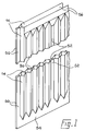
- each portion 14 has a corrugated configuration, providing therein valleys 30 separated by peaks, and the peaks of each portion are disposed opposite one another.
- the corrugations extend parallel with one another and at opposite ends of the rows of corrugations and extending parallel therewith are lands or flanges 50 (only end being shown in Figure 1) which again are in opposed relationship.
- lands or flanges 50 at intermediate positions between the corrugations are further lands or flanges 52, again arranged in opposed relationship.
- the lands or flanges 50, 52 are relatively wide in relation to the peaks of the corrugations and provide regions in which the two portions 14 of sheet material can be secured together in a reliable manner.
- a further land or flange 54 is also provided, extending transversely of the direction of the corrugations, along a bottom edge of each portion 14, the arrangement being such that, as can be seen from Figure 1, the land or flange 54 lies in a plane in which the peaks of the corrugations are disposed; that is to say, the corrugations themselves project from the plane of the flange 54. Furthermore, the flanges 50, 52 are in the same plane as the flange 54. In this way, an integral "frame" is provided around three sides of each portion 14 and thus, in the finished filter unit when the flanges are secured together, around three sides of the unit itself.
- each portion 14 furthermore, is another land or flange 56, which also extends transversely of the direction of the corrugations.
- the flange 56 of each portion lies not in the plane of the flanges 50, 52, 54 but rather in the plane of the bottoms of the valleys 30 provided by the corrugations.
- each portion may comprise a portion of a non-woven fibre felt produced using a blend of 50% by weight 1.7 decitex/60mm and 50% by weight 3.3 decitex/60mm staple polyimide fibres supplied under the designation P84 by Lenzing AG.
- the weight of the flexible fibre felt produced by the needle punching operation is about 400 grammes/sqm and the gauge about 3.5mm.
- These polyimide fibres are suitable for use in filter units operating at temperatures up to about 200°C. These fibres moreover are very suitable for use in conditions where chemicals are present and also they are not soluble in any known solvent.
- a non-woven fibre felt may be used comprising polyphenylene sulphide resin fibres of 3.3 decitex and 50mm length, such fibres being supplied under the designation Ryton PPS fibres by Phillips Fibers Corporation.
- the weight and gauge of the flexible fibre felt produced is generally similar to that of Example 1 and the fibres are suitable for use in filter assemblies operating at continuous temperatures of up to about 180°C. These fibres moreover are very suitable for use in conditions where chemicals are present.
- the material used may be produced from a blend of 50% by weight 1.5 decitex/50mm and 50% by weight 3.0 decitex/50mm staple polyester fibre or again a fibre felt may be used which comprises a blend of polyester fibres and polypropylene fibres in a ratio of 70:30 parts by weight, the polyester fibres being of 1.5 decitex/50mm and the polypropylene fibres 2.8 decitex/50mm.
- the filter units would be intended for use at lower temperatures than the first-mentioned units.
- bi-component fibres may be used, especially those of the concentric type having a core of a higher melting point and sheath of a lower melting point.
- the two portions 14 of sheet material are first formed into the corrugated configuration with intermediate and transversely extending lands, and are rendered rigid in such configuration. Thereafter the two portions are secured together along the lands 50, 52, 54 by any suitable means.
- they may be secured together by adhesive bonding or by stitching or indeed by metallic fastenings, including eyelets and, in the case of the edges, metallic clip members, as will be described hereinafter.
- the portions may also be secured together, for additional security, along the peaks of the corrugations thereof.
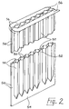
- Figure 2 shows an alternative unit which is generally similar to that shown in Figure 1 but distinguished in that during the forming of each portion 14 and prior to its being rendered rigid, the land or flange 56 formed along the top edge of the portions is out-flanged (as shown at 56 a in Figure 2) and thus may provide a means for supporting the finished filter unit in a connection with a suction or other air-drawing source.
- Figure 4 shows a cross-sectional view through a finished filter unit in which the lands 52 are secured together by eyelets 60 while the lands 50 are secured together by an elongated metallic clip member 62.
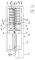
- the apparatus comprises a frame 100 at a right-hand end (viewing Figure 5) of which is disposed a forming assembly comprising two sets of blade members 102, each blade member being elongated and having an edge portion, facing the other set, of triangular cross-sectional configuration, thus forming a peak and the side faces of each two adjacent blade members providing a valley bounded by two peaks, the arrangement being such that each blade member of one set is disposed opposite a valley of the other set.
- the apparatus further comprises a pair of nip rolls 104 for assisting in the feeding of material from a continuous source thereof (not shown) to the forming assembly, nip rolls 104 being arranged "upstream" of the sets of blade members 102, while “downstream” of the sets of blade members is a clamp arrangement comprising two opposed clamp members 106 opposed surfaces of which are corrugated so as to receive therebetween a corrugated portion of the sheet material, as will be described hereinafter.
- a workpiece feeding device generally designated 108 comprising two opposed feeding members 110, the opposed surfaces of which respectively comprise a peak and cooperating valley, said members being mounted for sliding movement together in a direction away from the sets of blade members 102 whereby, with the blade members 102 and the clamp members 106 in a retracted condition, the sheet material can be fed through the apparatus from the continuous source thereof.
- the distance through which the members 110 move as aforesaid is fixed and corresponds to the length, in the feed direction, of the blade members 102.
- severing means Downstream of the workpiece feeding means 108, furthermore is severing means generally designated 112, said means comprising a vertically reciprocable blade extending transversely of the workpiece feed direction.
- the left-hand (viewing Figure 5) blade member 102 d of the upper set is not formed with a peak but rather with a flattened ridge 114, while the left-hand member 102 b of the lower set has formed therewith an integral flat surface 116 cooperable with the flattened surface 114.
- the cooperating surfaces of the clamp members 106 are further flattened portions 118, 120 which cooperate with the flat surfaces 114, 116 thus to provide, during the forming operation, a land 50 (or 52) extending parallel with the corrugations formed by the blade members and intermediate such corrugations, as described previously.
- the cutting or severing means 112 is spaced, in the direction of work feed, from the surfaces 114-120 by a distance which is a multiple of the length, also measured in the work feed direction, of the sets of blade members 102. It will thus be appreciated that, as the work is fed, the lands 50 (or 52) provided by the surfaces 114-120 are disposed beneath the cutting or severing means 112.
- the right-hand blade member 102 c of the upper set is also provided with a flattened surface 122 instead of a peak, corresponding to the flat surface 118 on the upper clamp member 106, and similarly the right-hand blade member 102 a of the lower set is provided with a flat surface extension 124 cooperable with the flattened surface 122 and corresponding to the surface 120 of the right-hand end of the lower clamp member 106.
- the surfaces 122, 124 cooperate to form part of a land or flange 50 (or 52) which, after the work has been fed through a predetermined distance as aforesaid is then disposed between the surfaces 118, 120 of the clamp members 106.
- the blade members 102 are individually advanced between a retracted position and an advanced position in which a length of the sheet material disposed therebetween is thus formed into a corrugated configuration as aforesaid. More particularly, with a portion of formed sheet material held by the clamp members 106, the left-hand blade member 102 d of the upper set is first advanced into engagement with the sheet material (as shown in Figure 6) and thereafter the left-hand member 102 b of the lower set is advanced thus to form a first half of a first corrugation in the sheet material (see Figure 7).
- Each of the blade members is then in sequence, starting from the left-hand side, moved into engagement with the sheet material, which is thus progressively drawn from its continuous supply, and more particularly the blade members of the two sets are advanced alternately, the last blade member to be advanced thus being the right-hand end member 102 c of the upper set.
- the blade members are each provided with heating means 130 for heating the sheet to an appropriate temperature such that upon being held in this corrugated configuration by the blade members, the sheet material is rendered rigid.
- the period during which the material is thus held is also of course determined according to the nature of the material itself.
- the workpiece feed members 110 are moved to engage a previously formed portion of the material as aforesaid, the clamp members 106 then being retracted.
- the feed members 110 are then advanced through the predetermined distance and the most recently formed portion of the sheet material is thus advanced from between the blade members, drawing another portion of unformed material between said members.
- the clamp members 106 are then once more advanced into an operative, clamping, condition, the feed members 110 are retracted out of engagement with the formed material and are thereafter returned to their initial position.
- the cutting or severing means is appropriately actuated or remains unactuated.
- the operating cycle is then repeated.
- each blade member of the upper set has formed at one end thereof a flattened portion 126 while each blade member of the lower set has a cooperating flattened surface 138.
- the surface 126 lies in the plane of the peak of the portion of triangular cross-section of the blade member 102 of the upper set, while the flattened surface 128 lies in the plane of the bottom of the portion of triangular cross-section (and thus of the valleys formed between adjacent blade members) of the lower set.
- the land or flange 54 will lie in the same plane as the lands 50, 52.
- each blade member 102 furthermore, is formed a further flattened surface (not shown) generally similarly to those shown in Figure 3, except that the flattened surface provided on each blade member of the upper set lies in this case in the plane of the bottom of the portion of triangular cross-section, while in the case of the lower set the flattened surface lies in the plane of the peak provided by the portion of triangular cross-section.
- the land or flange 56 will lie in the plane of the bottoms of the valleys of corrugated configuration.
- the apparatus allows a continuous through-feed method to be practised, using a fabric sheet material in a continuous roll form, and the individual portions can be cut, centrally of one of the lands 50 (or 52) formed as aforesaid, by the severing means 112 according to the lengths required.
- the out-flanged portion 56 a of the finished unit itself enables a connection to be made with a suction or air-drawing source.
- such out-flanged portion may be reinforced by one or more layers of a similar or the same material secured thereto by any desired means.
Landscapes
- Chemical & Material Sciences (AREA)
- Chemical Kinetics & Catalysis (AREA)
- Physics & Mathematics (AREA)
- Geometry (AREA)
- Filtering Materials (AREA)
- Filtering Of Dispersed Particles In Gases (AREA)
- Treatment Of Fiber Materials (AREA)
Abstract
Description
- This invention is concerned with a method of manufacturing a self-supporting filter unit, an apparatus suitable for use in carrying out such a method, said apparatus including a forming assembly, and also a self-supporting filter unit made using such a method.
- Known dust filter units are in the form of bags which are supported against collapse by a framework of metal or other suitable material, air to be filtered being sucked through the bags from outside to the interior thereof so that dust particles and/or other debris are prevented by the material of the bags from passing to the interior and thus collected on the outer surface; the pore size of the fabric of these filter bags is selected according to the size of dust particles to be filtered from the gas flow.
- Self-supporting filter units, i.e. units which do not require a framework of metal or other suitable material, are available; one such unit is supplied under the trademark "SINTAMATIC" by DCE Limited of Thurmaston, Leicester. This filter unit comprises a porous composite which is rigid and self-supporting, being made by a process in which a blend of granulated engineering polymers is dimensionally restrained and processed to produce a rigid porous composite element. The surface of this element is then treated with a P.T.F.E.-based solution to form a micro-porous skin. While this self-supporting filter has been shown to be generally satisfactory in performance, it is somewhat expensive to provide and the production process is relatively complex.
- It is thus one of the various objects of the present invention to provide an improved method of manufacturing a self-supporting filter unit implementation of which is less expensive and more readily achievable than previous methods.
- It is another of the various objects of the present invention to provide a forming assembly for use in forming flexible non-woven fabric sheet materials to provide corrugations therein and subsequently for treating such material whilst in its corrugated configuration, such assembly being especially useful in the manufacture of self-supporting filter units.
- The invention thus provides in one of its several aspects a method of manufacturing a self-supporting filter unit comprising forming a flexible non-woven fabric sheet material to provide corrugations therein, treating the material to render it rigid whilst in its corrugated configuration, and securing two portions of the rigid corrugated material together with corrugations parallel, the portions being secured together in such a manner that the peaks provided by the corrugations are in opposed relation and thus the valleys between the peaks are in register, each opposed pair of valleys providing a passage having air-permeable walls through which, in the finished unit, air to be filtered can pass and be drawn off but which prevent the passage therethrough of dust and/or other debris, wherein in forming the material lands are provided at spaced intervals between the corrugations in the plane of the peaks thereof and extending parallel with the corrugations, and wherein the portions of the material are secured together along the lands.
- It will be appreciated that, by the provision of lands at spaced intervals between the corrugations, which lands provide a more effective area over which the two portions of material can be secured together, a more reliable filter unit is provided, and at the same time the handling of the portions prior to their being secured together is facilitated.
- In order to enhance the securing of the portions together, preferably in forming the material a further land is provided also in the plane of the peaks of the corrugations and extending transversely of the corrugations formed in the material, and thereafter in securing the portions of material together the further lands provided in the portions are arranged in opposed relation, thus serving to close one end of the passages provided by the corrugations, and are secured together. Furthermore, it has been found advantageous to provide a still further land in the sheet material, also extending transversely of the corrugations but in the plane of the bottoms of the valleys thereof, and, in securing the portions of material together, said still further lands are held spaced apart, thus to form in the finished filter unit an opening into which all the passages open and in which a connection to a suction unit can be accommodated. Alternatively, and in a preferred embodiment, said still further land is flanged outwardly from the plane of the bottoms of the valleys of the corrugations about a line passing through said bottoms, thus to form a connecting piece into which the passages open and by which the unit can be connected to a suction source.
- In this way, it will be appreciated, effectively an integral frame can be provided around the whole of the filter unit manufactured in accordance with this method and also in this integral unit is provided a facility for connecting the finished filter unit to a suction source. In carrying out the method in accordance with the invention the portions of sheet material may be secured together as aforesaid by adhesive bonding or by eyeletting or other suitable metallic fastenings. In addition, if desired, and for extra security, the peaks in the material may also be secured together by adhesive bonding.
- The fabric sheet material used in carrying out the method in accordance with the invention preferably contains fibres which will desirably be selected according to the use to which the filter is to be put, will have suitable decitex and will be formed into a fibre fabric by one of the known production techniques for non-woven fibre fabric to provide a desired fabric density. One such technique involves the production of a fibre felt by a carding and needle punching process, the weight per unit area of the felt, the needle size and the needle punch density being selected according to the desired final application. Thus, in one example the fibre fabric is a non-woven fabric made from polyimide fibres which become rigid when heated at temperatures above the glass transition temperature of the fibres. One suitable polyimide fibre is supplied under the designation P84 by Lenzing AG. P84 fibres have a strong tendency, especially when heated to the glass transition temperature, which is in the order of 315°C, to shrink and in this way the fabric made therefrom accurately takes the shape of the formers and/or presser members, providing a well-defined filter unit with well-finished surfaces and good internal strength to render the filter self-supporting.
- Instead of using fibres which rigidise upon being heated, a non-woven fabric made from thermoplastic fibres may be used. In this case, it is important, in order to maintain the air-permeability of the material, that the fibres are not in fact melted but are in fact heated close to their melting point firstly to provide a degree of shrinkage, in order to ensure a well-defined filter unit, and secondly in order to soften the fibres and cause them to bond together without however forming a continuous film. One such material is made from polyphenylene sulphide fibres, more particularly a fibre obtained from Phillips Fibers Corporation under the designation Ryton PPS fibres. Such fibres have a melting point in the order of 285°C and are capable of operating at temperatures up to 190°C on a continuous basis, or somewhat higher temperatures in surges. In addition these fibres have excellent resistance to a wide range of acids and alkalines and are not soluble in any known solvent below 200°C. Furthermore, the material made from such fibres is classified as non-inflammable.
- As an alternative to thermoplastic fibre, polyester fibre may be used generally in the same manner as in using the Ryton fibres. In this case of course the melt temperature of the fibres is somewhat lower, being in the order of 240°C, and self-supporting filter units from fabrics comprising polyester fibres are clearly useful only at much lower operating temperatures than the Ryton fibre fabric or the P84 fibre fabric. Nevertheless, a satisfactory self-supporting filter unit can be produced from such fabrics using the process in accordance with the present invention.
- It is also possible to use fibre fabrics which are made from mixtures of fibres. For example, one material which has been found suitable comprises 55 to 80 parts by weight polyester fibres and 45 to 20 parts by weight polypropylene fibres, the actual ratio of polyester fibres to polypropylene fibres being 70:30 parts by weight. In this case, it will be appreciated, the polypropylene fibres have a lower melt temperature than the polyester fibres so that it is possible, by the application of heat to a temperature above the melt temperature of the polypropylene but below the melt temperature of the polyester, to melt the polypropylene fibres and cause the molten polypropylene to flow among the polyester fibres to bond them together, the application of heat at the same time causing significant shrinkage of the polypropylene fibres and shrinkage also, but to a lesser extent, of the polyester fibres, so that the fabric closely conforms to the shape of the formers and/or press members, resulting in a well-defined filter unit having good self-supporting properties.
- As yet another example, moreover, the fabric may be made up of a mixture of bi-component fibres and other suitable fibres, where at least 5% parts by weight of bi-component fibres are used. The feature of bi-component fibres is of course that one of the components has different properties from the other, usually a lower melt point, so that again by the application of heat up to the melt temperature of the one component, but falling short of the melt temperature of the other component, said one component can flow and serve to bond not only the other fibres, but also the other component of the bi-component fibres with a result that the fabric is stiffened, the application of heat at the same time usually causing shrinkage to some extent of all the fibres, resulting in a well-defined filter unit having good self-supporting properties.
- As a further alternative, a non-woven fabric may be used which is impregnated with a suitable quantity of a resinous stiffening material which material may stiffen with or without the application of heat. Such stiffening material may be supplied as a latex with a relatively low pick-up, e.g. 10% to 30% by weight of the non-woven fibre fabric. As examples of such a latex, furthermore, reference is made to styrene homopolymer and copolymer latices.
- Within the scope of the invention, furthermore it is contemplated that multi-layer fabrics may be used, the various layers exhibiting different desirable properties for the production of a self-supporting filter unit. For example, an outer surface layer would desirably provide for easy release of dust and/or other debris adhering thereto, while an inner surface layer would have no tendency to adhere to the formers during the manufacturing process, and in addition each layer of the fabric would exhibit one or both of the following properties, namely good filtration of air passing therethrough and the necessary rigidity to render the filter unit self-supporting.
- In carrying out a preferred method in accordance with the invention, furthermore, the sheet material is progressively formed to provide the corrugations and the lands, therein, each section of the material thus formed being treated to render it rigid prior to the forming of a next-following section.
- The invention further provides, in another of its several aspects, a forming assembly for forming flexible non-woven fabric sheet material to provide corrugations therein and subsequently for treating such material whilst in its corrugated configuration, comprising a clamp arrangement having two elongated clamp members each having a flat clamp surface, two opposed corrugating tools aligned with one another such that the peaks of the corrugating surface of one tool mate with the valleys of the corrugating surface of the other, and means for effecting relative movement of approach and separation between the clamp members and also between the corrugating tools, whereby material disposed therebetween can be formed into a corrugated configuration with a land extending parallel to the corrugations, wherein each corrugating tool comprises a plurality of elongated blade members, each extending parallel with the clamp members and each having a material-engaging end portion of generally triangular cross-section thus to provide an elongated peak and a valley being thus formed between the peaks of adjacent blade members, and wherein with a portion of sheet material held clamped by the clamping members and extending between the corrugating tools, the means for effecting relative movement between said tools is effective to advance each blade member of at least one of said tools in sequence, starting with the blade member whose peak is most closely adjacent the clamp members and thereafter the next most closely adjacent and so on.
- It will thus be appreciated that using such a forming assembly a "progressive" sheet-forming operation can be effected as part of the aforementioned method of manufacturing filter units, the material thus being formed in relatively long lengths from which portions can be obtained for the formation of filter units as aforesaid.
- Preferably in using an assembly as referred to as above the blade members of both tools are thus advanced in sequence, the arrangement thus being such that alternately a blade member of one tool and then a blade member of the other are thus advanced. In this way it can be more readily ensured that the material is evenly distributed between the blade members as they are progressively closed onto it.
- Conveniently, moreover, one of the clamping members is formed integral with one of the blade members of one of the tools, and the other tool has associated with it a separate clamping member having a cut-away portion forming a side of a valley-cooperating with the peak of said one blade member of said one of the tools.
- For the treatment of materials which are rendered rigid as aforesaid by the application of heat, furthermore, preferably, heating means is provided for heating the tools to a temperature at which the fabric sheet material therebetween is rendered rigid.
- In a preferred embodiment of the forming assembly each blade member has a flat forming face extending transversely of the corrugations adjacent one end thereof whereby as the blade members are moved together an edge portion of the material is clamped between the flat forming surface of the cooperating members thus progressively to form a land along said edge portion; in such a case, moreover, the flat surfaces of the blade members of one of the tools lie in the plane of the bottoms of the valleys of the corrugated surfaces thereof, while those of the other of the tools lie in the plane of peaks of the corrugated surfaces thereof. Similarly, in said preferred embodiment each blade member has a further flat forming surface extending transversely of the corrugations thereof for forming a land along the opposite edge portion of the material and, furthermore, in the blade members where the flat surfaces adjacent one end are in the plane of the peaks of the corrugated surfaces thereof, those adjacent the other end are in the plane of the bottoms of the valleys of said surfaces, and vice versa. It will thus be appreciated that, in using this preferred embodiment of the forming assembly, the additional lands formed by the flat forming surfaces provide the closures and also the facility for providing a connection to a suction source, as described earlier in relation to the method of manufacture.
- The invention also provides, in another of its several aspects, an apparatus suitable for use in the manufacture of filter units from flexible non-woven fabric sheet material, comprising an assembly as set out above, means for feeding the material through the apparatus from a continuous supply, and severing means for severing formed rigid portions from the material, wherein the feed means comprises cooperating members providing a complementary peak-and-valley arrangement for engaging in one or more corrugations in the formed rigid material, and means for moving the members bodily through a predetermined distance equivalent to the dimension of the tools as measured in the direction of feed of the material, whereby the material is fed section-by-section through the apparatus, each section comprising a plurality of configurations with a parallel land at one end thereof.
- Using such an apparatus, it will be appreciated, a progressive forming operation can thus readily be achieved. Moreover, preferably the severing means is disposed in a position such that as each section of material is fed as aforesaid the land provided by the clamping means is positioned in opposed relation with the severing means and thus the section is severed along said land. In this way the land is effectively divided into two so that along each edge of a portion from which a filter unit is to be formed by being secured to another portion, a sufficient area is provided along such edge to ensure that the two portions are properly and reliably secured together.
- The feed means of said apparatus is preferably of the orbital type, i.e. advances in contact with the material in one direction and then is subsequently returned in an opposite direction, out of contact with the material, to its initial position, and in such a case preferably a further clamp arrangement is provided, comprising further cooperating members also providing a complementary peak-and-valley arrangement and engageable also with a formed rigid portion of the material, whereby the material is held in position during return movement, out of engagement with the material, of the cooperating members of the feeding means.
- In order to ensure that the material is held securely and is positioned accurately laterally of the apparatus as it is fed therethrough, furthermore, preferably the means for feeding the material also comprises means for holding the material long outside edges thereof along the feed direction. Such means may be in the form of e.g. stentering pins mounted on continuous belts along each side of the feed path of the material.
- The invention still further provides, in yet another of its several aspects, a self-supporting filter unit comprising two portions of a rigid sheet material formed with corrugations and bounded at each side by a land, the portions being secured together along said lands such that the corrugations of the portions are disposed peak-to-peak whereby passages are formed thereby, said passages being defined by wall portions which are air-permeable and through which air can pass and be drawn off but which prevent the passage therethrough of dust and/or other debris, wherein each portion also has a further land, extending transversely of the corrugations and in the plane of the peaks of the corrugations, said further lands also being secured together thus to close one end of each of the passages.
- The above and other of the various objects and several aspects of the invention will become clearer from the following detailed description to be read with reference to the accompanying drawings, of a method of manufacturing a self-supporting filter unit, an apparatus including a forming assembly and a self-supporting filter unit. It will of course be appreciated that the method, apparatus (including an assembly) and unit to be described hereinafter have been selected for description merely by way of non-limiting example of the invention.
- In the accompanying drawings:-
- Figure 1 is a perspective view showing two portions of fabric sheet material which have been formed and which, when secured together, will constitute a filter unit in accordance with the invention;
- Figure 2 is a view generally similar to Claim 1, but wherein the forming of the sheet materials has been modified;
- Figure 3 is a fragmentary perspective view of opposed bland members forming part of a forming assembly by which sheet material can be formed;
- Figure 4 is a sectional view through a unit made by a method in accordance with the present invention;
- Figure 5 is a schematic diagram of an apparatus in accordance with the invention; and
- Figures 6 and 7 are views similar to Figure 5, but showing a sequence of operations of said apparatus.
- With reference to Figure 1, two
portions 14 of a flexible fibre fabric sheet material are placed in opposed relationship. Eachportion 14 has a corrugated configuration, providing thereinvalleys 30 separated by peaks, and the peaks of each portion are disposed opposite one another. The corrugations extend parallel with one another and at opposite ends of the rows of corrugations and extending parallel therewith are lands or flanges 50 (only end being shown in Figure 1) which again are in opposed relationship. In addition, at intermediate positions between the corrugations are further lands orflanges 52, again arranged in opposed relationship. The lands orflanges portions 14 of sheet material can be secured together in a reliable manner. - A further land or
flange 54 is also provided, extending transversely of the direction of the corrugations, along a bottom edge of eachportion 14, the arrangement being such that, as can be seen from Figure 1, the land orflange 54 lies in a plane in which the peaks of the corrugations are disposed; that is to say, the corrugations themselves project from the plane of theflange 54. Furthermore, theflanges flange 54. In this way, an integral "frame" is provided around three sides of eachportion 14 and thus, in the finished filter unit when the flanges are secured together, around three sides of the unit itself. - At the top end of each
portion 14, furthermore, is another land orflange 56, which also extends transversely of the direction of the corrugations. In this case, however, theflange 56 of each portion lies not in the plane of theflanges valleys 30 provided by the corrugations. It will thus be appreciated that, when the twoportions 14 are, as shown in Figure 1, arranged in opposed relationship, thus forming therebetween an opening in which a suitable connection, by which passages formed by the valleys of the portions can be connected to a suction or an air-drawing source. - Various material may be used from which the
portions 14 of sheet material can be made. For example, each portion may comprise a portion of a non-woven fibre felt produced using a blend of 50% by weight 1.7 decitex/60mm and 50% by weight 3.3 decitex/60mm staple polyimide fibres supplied under the designation P84 by Lenzing AG. The weight of the flexible fibre felt produced by the needle punching operation is about 400 grammes/sqm and the gauge about 3.5mm. These polyimide fibres are suitable for use in filter units operating at temperatures up to about 200°C. These fibres moreover are very suitable for use in conditions where chemicals are present and also they are not soluble in any known solvent. - Alternatively, a non-woven fibre felt may be used comprising polyphenylene sulphide resin fibres of 3.3 decitex and 50mm length, such fibres being supplied under the designation Ryton PPS fibres by Phillips Fibers Corporation. The weight and gauge of the flexible fibre felt produced is generally similar to that of Example 1 and the fibres are suitable for use in filter assemblies operating at continuous temperatures of up to about 180°C. These fibres moreover are very suitable for use in conditions where chemicals are present.
- Again, the material used may be produced from a blend of 50% by weight 1.5 decitex/50mm and 50% by weight 3.0 decitex/50mm staple polyester fibre or again a fibre felt may be used which comprises a blend of polyester fibres and polypropylene fibres in a ratio of 70:30 parts by weight, the polyester fibres being of 1.5 decitex/50mm and the polypropylene fibres 2.8 decitex/50mm. In each of these cases the filter units would be intended for use at lower temperatures than the first-mentioned units. Again, moreover, bi-component fibres may be used, especially those of the concentric type having a core of a higher melting point and sheath of a lower melting point.
- Whichever material is used, it can be rendered rigid, and thus self-supporting, by the application of heat and, in carrying out the method in accordance with the invention, the two
portions 14 of sheet material are first formed into the corrugated configuration with intermediate and transversely extending lands, and are rendered rigid in such configuration. Thereafter the two portions are secured together along thelands - Figure 2 shows an alternative unit which is generally similar to that shown in Figure 1 but distinguished in that during the forming of each
portion 14 and prior to its being rendered rigid, the land orflange 56 formed along the top edge of the portions is out-flanged (as shown at 56a in Figure 2) and thus may provide a means for supporting the finished filter unit in a connection with a suction or other air-drawing source. - Figure 4 shows a cross-sectional view through a finished filter unit in which the
lands 52 are secured together byeyelets 60 while thelands 50 are secured together by an elongatedmetallic clip member 62. The peaks of the corrugations, as shown in this Figure, furthermore, are secured by adhesive designated 64. - For forming the fibre felt sheet material and rendering it rigid while in its formed configuration, an apparatus is used, as shown in Figure 5 in a schematic form. The apparatus comprises a
frame 100 at a right-hand end (viewing Figure 5) of which is disposed a forming assembly comprising two sets ofblade members 102, each blade member being elongated and having an edge portion, facing the other set, of triangular cross-sectional configuration, thus forming a peak and the side faces of each two adjacent blade members providing a valley bounded by two peaks, the arrangement being such that each blade member of one set is disposed opposite a valley of the other set. - The apparatus further comprises a pair of nip rolls 104 for assisting in the feeding of material from a continuous source thereof (not shown) to the forming assembly, nip
rolls 104 being arranged "upstream" of the sets ofblade members 102, while "downstream" of the sets of blade members is a clamp arrangement comprising twoopposed clamp members 106 opposed surfaces of which are corrugated so as to receive therebetween a corrugated portion of the sheet material, as will be described hereinafter. Further downstream of theclamp members 106, furthermore, is a workpiece feeding device generally designated 108 comprising two opposed feedingmembers 110, the opposed surfaces of which respectively comprise a peak and cooperating valley, said members being mounted for sliding movement together in a direction away from the sets ofblade members 102 whereby, with theblade members 102 and theclamp members 106 in a retracted condition, the sheet material can be fed through the apparatus from the continuous source thereof. The distance through which themembers 110 move as aforesaid is fixed and corresponds to the length, in the feed direction, of theblade members 102. - Downstream of the workpiece feeding means 108, furthermore is severing means generally designated 112, said means comprising a vertically reciprocable blade extending transversely of the workpiece feed direction.
- The left-hand (viewing Figure 5)
blade member 102d of the upper set is not formed with a peak but rather with a flattenedridge 114, while the left-hand member 102b of the lower set has formed therewith an integralflat surface 116 cooperable with the flattenedsurface 114. In addition, at the right-hand end of the cooperating surfaces of theclamp members 106 are further flattenedportions flat surfaces blade members 102. It will thus be appreciated that, as the work is fed, the lands 50 (or 52) provided by the surfaces 114-120 are disposed beneath the cutting or severing means 112. - It will also be noted from Figure 5 that the right-
hand blade member 102c of the upper set is also provided with a flattenedsurface 122 instead of a peak, corresponding to theflat surface 118 on theupper clamp member 106, and similarly the right-hand blade member 102a of the lower set is provided with aflat surface extension 124 cooperable with the flattenedsurface 122 and corresponding to thesurface 120 of the right-hand end of thelower clamp member 106. Thus, in a forming operation, thesurfaces surfaces clamp members 106. - In the operation of the apparatus, the
blade members 102 are individually advanced between a retracted position and an advanced position in which a length of the sheet material disposed therebetween is thus formed into a corrugated configuration as aforesaid. More particularly, with a portion of formed sheet material held by theclamp members 106, the left-hand blade member 102d of the upper set is first advanced into engagement with the sheet material (as shown in Figure 6) and thereafter the left-hand member 102b of the lower set is advanced thus to form a first half of a first corrugation in the sheet material (see Figure 7). Each of the blade members is then in sequence, starting from the left-hand side, moved into engagement with the sheet material, which is thus progressively drawn from its continuous supply, and more particularly the blade members of the two sets are advanced alternately, the last blade member to be advanced thus being the right-hand end member 102c of the upper set. - The blade members are each provided with heating means 130 for heating the sheet to an appropriate temperature such that upon being held in this corrugated configuration by the blade members, the sheet material is rendered rigid. The period during which the material is thus held is also of course determined according to the nature of the material itself.
- At the end of this stage of the operation in which forming and rendering rigid of the material takes place, the
workpiece feed members 110 are moved to engage a previously formed portion of the material as aforesaid, theclamp members 106 then being retracted. Thefeed members 110 are then advanced through the predetermined distance and the most recently formed portion of the sheet material is thus advanced from between the blade members, drawing another portion of unformed material between said members. Theclamp members 106 are then once more advanced into an operative, clamping, condition, thefeed members 110 are retracted out of engagement with the formed material and are thereafter returned to their initial position. Depending upon whether the land 50 (or 52) now disposed beneath the cutting or severing means 112 is to form an end potion of the finished workpiece or merely an intermediate land, the cutting or severing means is appropriately actuated or remains unactuated. - The operating cycle is then repeated.
- For forming the
lands 54 on the sheet material, each blade member of the upper set has formed at one end thereof a flattenedportion 126 while each blade member of the lower set has a cooperating flattened surface 138. As will be seen from Figure 3, thesurface 126 lies in the plane of the peak of the portion of triangular cross-section of theblade member 102 of the upper set, while the flattenedsurface 128 lies in the plane of the bottom of the portion of triangular cross-section (and thus of the valleys formed between adjacent blade members) of the lower set. Thus, in the finished formedportion 14, the land orflange 54 will lie in the same plane as thelands - At the opposite end of each
blade member 102, furthermore, is formed a further flattened surface (not shown) generally similarly to those shown in Figure 3, except that the flattened surface provided on each blade member of the upper set lies in this case in the plane of the bottom of the portion of triangular cross-section, while in the case of the lower set the flattened surface lies in the plane of the peak provided by the portion of triangular cross-section. Thus, in the finished formed portion the land orflange 56 will lie in the plane of the bottoms of the valleys of corrugated configuration. - As an alternative to such an arrangement as described in the last paragraph, in order to produce an outwardly flanged portion as described with reference to Figure 2 above, the appropriate ends of the blade members terminate in a perpendicular plane (as opposed to the tapering of the triangular cross-sectional portions, as illustrated in Figure 3) and thus, when the sheet material has been trapped between the blade member as described above, a portion thereof projects free beyond the end of the blade members, this projecting portion then being folder over the end of the blade members and pressed against a flat forming surface which extends in said perpendicular plane. In this way a rigid integral out-flange 56a can be provided.
- In carrying out the method in accordance with the present invention, it will be plain, the apparatus above-described can thus readily be used. In particular, it will be appreciated that using such apparatus a sheet material portion is fed, from a continuous supply thereof, between the
blade members 102, by which it is progressively clamped, thus to form a corrugated configuration, and at the same time, by reason of the blade members being heated to an appropriate temperature the material is treated to render it rigid. Because of the particular configuration of the end blade members 102a-d, moreover, at spaced intervals along the length of the sheet material, intermediate the corrugations, lands 50, 52 are formed, for the purposes described above. At the same time, by reason of the flattenedsurfaces lands - The apparatus allows a continuous through-feed method to be practised, using a fabric sheet material in a continuous roll form, and the individual portions can be cut, centrally of one of the lands 50 (or 52) formed as aforesaid, by the severing means 112 according to the lengths required.
- When the portions of material have been formed, rendered rigid and severed as aforesaid, moreover, two portions are then arranged in face-to-face contact, with their corrugations parallel and with the peaks thereof in opposed relationship and the valleys between the peaks in register such that each valley provides a passage through which, in the finished unit, air to be filtered can pass and be drawn off, but which prevents the passage therethrough of dust and/or other debris, and the two portions are then secured together through the
various lands - In the case where the
lands 56 extend in the plane of the bottoms of the valleys, moreover, in carrying out the method, a suitable connection is then disposed in the opening formed by thelands 56. In manufacturing the alternative embodiment of Figure 2 the out-flanged portion 56a of the finished unit itself enables a connection to be made with a suction or air-drawing source. Moreover, if desired, such out-flanged portion may be reinforced by one or more layers of a similar or the same material secured thereto by any desired means.
Claims (12)
- A method of manufacturing a self-supporting filter unit characterised by the steps of
forming a flexible non-woven fabric sheet material to provide corrugations therein,
treating the material to render it rigid whilst in its corrugated configuration, and
securing two portions (14) of the rigid corrugated material together with corrugations parallel, the portions being secured together in such a manner that the peaks provided by the corrugations are in opposed relation and thus the valleys (30) between the peaks are in register, each opposed pair of valleys (30) providing a passage having air-permeable walls through which, in the finished unit, air to be filtered can pass and be drawn off but which prevent the passage therethrough of dust and/or other debris,
and further characterised in that in forming the material lands (52) are provided at spaced intervals between the corrugations in the plane of the peaks thereof and extending parallel with the corrugations, along which lands (52) the portions (14) of the material are secured together. - A method according to Claim 1 characterised in that in forming the material a further land (54) is provided also in the plane of the peaks of the corrugations and extending transversely of the corrugations formed in the material,
and in that in securing the portions (14) of material together the further lands (54) provided in the portions (14) are arranged in opposed relation, thus serving to close one end of the passages provided by the corrugations, and are secured together. - A method according to either one of Claims 1 or 2 characterised in that a still further land (56) is provided in each portion (14) of the sheet material, also extending transversely of the corrugations but in the plane of the bottoms of the valleys (30) thereof,
and in that in securing the portions 914) of material together said still further lands (56) are held spaced apart, thus to form in the finished filter unit an opening into which all the passages open. - A method according to any one of the preceding Claims characterised in that the sheet material is progressively formed to provide the corrugations and the lands therein,
and in that each section of the material thus formed is treated to render it rigid prior to the forming of a next-following section. - A forming assembly for forming flexible non-woven fabric sheet material to provide corrugations therein and subsequently for treating such material whilst in its corrugated configuration, characterised by
a clamp arrangement having two elongated clamp members (106) each having a flat clamp surface (120),
two opposed corrugating tools (102) aligned with one another such that the peaks of the corrugating surface of one tool mate with the valleys of the corrugating surface of the other, and
means for effecting relative movement of approach and separation between the clamp members (106) and also between the corrugating tools (102), whereby material disposed therebetween can be formed into a corrugated configuration with a land extending parallel to the corrugations,
and further characterised in that each corrugating tool comprises a plurality of elongated blade members (102), each extending parallel with the clamp members (106) and each having a material-engaging end portion of generally triangular cross-section thus to provide an elongated peak and a valley being thus formed between the peaks of adjacent blade members,
and in that with a portion of sheet material held clamped by the clamp members (106) and extending between the corrugating tools (102), the means for effecting relative movement between said tools (102) is effective to advance each blade member (102) of at least one of said tools in sequence, starting with the blade member (102d) whose peak is most closely adjacent the clamp members (106) and thereafter the next most closely (102b) adjacent and so on. - An assembly according to Claim 5 characterised in that the blade member (102d; 102b) of each tool adjacent the clamp members (106) has a flattened surface (114; 116), said surfaces cooperating with the flattened surfaces (120) of the clamp members (106) to form two opposed continuous clamp surfaces of the width of a land to be formed in the material, and further in that the blade member (102c; 102a) of each tool remote from the clamp members (106) also has a flattened surface (122; 124) of corresponding dimensions to the surfaces (120) of the clamp members (106).
- An assembly according to either one of Claims 5 and 6 characterised in that heating means (130) is provided for heating the tools (102) to a temperature at which the fabric sheet material therebetween is rendered rigid.
- An assembly according to any one of Claims 5 to 7 characterised in that each blade member (102) has at least one flat forming face (128) extending transversely of the corrugations adjacent one end thereof whereby as the blade members (102) are moved together an edge portion of the material is clamped between the flat forming surface (128) of the cooperating blade members (102) thus progressively to form a land (54) along said edge portion.
- Apparatus suitable for use in the manufacture of filter units from flexible non-woven fabric sheet material, characterised by
a forming assembly according to any one of Claims 5 to 8,
means (110) for feeding the material through the apparatus from a continuous supply, and
severing means (112) for severing formed rigid portions from the material,
and further characterised in that the feeding means (110) comprises cooperating members providing a complementary peak-and-valley arrangement for engaging in one or more corrugations in the formed rigid material, and means for moving the members (110) bodily through a predetermined distance equivalent to the dimension of the tools (102) as measured in the direction of feed of the material, whereby the material is fed section-by-section through the apparatus, each section comprising a plurality of configurations with a parallel land at one end thereof,
and in that severing means (112) is disposed in a position such that as each section of material is fed as aforesaid a land formed as aforesaid is positioned in opposed relation with the severing means (112) and thus the section can be severed along said land. - A self-supporting filter unit characterised by two portions (14) of a rigid sheet material formed with corrugations and bounded at each side by a land (50), and comprising an additional land or lands (52) intermediate the side lands (50), said lands (50, 52) extending parallel to the corrugations and the portions (14) being secured together along said lands (50, 52) such that the corrugations of the portions (14) are disposed peak-to-peak whereby passages are formed thereby, said passages being defined by wall portions which are air-permeable and through which air can pass and be drawn off but which prevent the passage therethrough of dust and/or other debris,
and further characterised in that each portion (14) also has a further land (54), extending transversely of the corrugations and in the plane of the peaks of the corrugations, said further lands (54) also being secured together thus to close one end of each of the passages. - A filter unit according to Claim 10 characterised in that at the other end of the passages each portion (14) of material has formed therein a still further land (56) extending transversely of the corrugations but in the plane of the bottoms of the valleys (30) of the corrugations, thus to form an opening into which the passages open and in which a connection member can be accommodated whereby the passages are connected to a suction source.
- A filter unit according to Claim 10 characterised in that at the other end of the passages each portion (14) of material has formed therein a still further land (56a) extending transversely of the corrugations and flanged outwardly from the plane of the bottoms of the valleys (30) of the corrugations about a line passing through said bottoms, thus to form a connecting piece into which the passages open and by which the unit can be connected to a suction source.
Applications Claiming Priority (2)
| Application Number | Priority Date | Filing Date | Title |
|---|---|---|---|
| GB9123926 | 1991-11-11 | ||
| GB919123926A GB9123926D0 (en) | 1991-05-04 | 1991-11-11 | Self-supporting filter unit |
Publications (2)
| Publication Number | Publication Date |
|---|---|
| EP0542396A2 true EP0542396A2 (en) | 1993-05-19 |
| EP0542396A3 EP0542396A3 (en) | 1993-09-29 |
Family
ID=10704429
Family Applications (1)
| Application Number | Title | Priority Date | Filing Date |
|---|---|---|---|
| EP19920303794 Withdrawn EP0542396A3 (en) | 1991-11-11 | 1992-04-27 | Self-supporting filter unit |
Country Status (4)
| Country | Link |
|---|---|
| US (1) | US5230455A (en) |
| EP (1) | EP0542396A3 (en) |
| JP (1) | JPH05277321A (en) |
| TW (1) | TW199108B (en) |
Cited By (7)
| Publication number | Priority date | Publication date | Assignee | Title |
|---|---|---|---|---|
| EP0692293A1 (en) * | 1994-07-12 | 1996-01-17 | Nittetsu Mining Co., Ltd. | Reinforced filter element |
| FR2849787A1 (en) * | 2003-01-15 | 2004-07-16 | Valeo Materiaux Friction | Golf putter comprises hosel shape and start point combining to force golfer to use writs positioned in front of club and produce straight trajectory |
| WO2004087298A3 (en) * | 2003-03-27 | 2005-01-20 | Valeo Materiaux De Friction | Method for making an air filter device, air filter device, device for implementing the method and airflow installation in a motor vehicle |
| WO2005051518A1 (en) * | 2003-11-18 | 2005-06-09 | Madison Filter 981 Limited | Filter element mounting apparatus |
| WO2006119835A1 (en) * | 2005-05-09 | 2006-11-16 | Carl Freudenberg Kg | Filter element |
| CN112622349A (en) * | 2020-12-14 | 2021-04-09 | 中山尚诚环保科技有限公司 | Air filtering device and production process thereof |
| CN115180224A (en) * | 2022-07-18 | 2022-10-14 | 巩义市泛锐熠辉复合材料有限公司 | Device and method for automatically impregnating and collecting sheet fibrofelt |
Families Citing this family (32)
| Publication number | Priority date | Publication date | Assignee | Title |
|---|---|---|---|---|
| CA2152602C (en) * | 1993-01-13 | 1999-06-29 | John James Bakula | Undulating screen for vibratory screening machine and method of fabrication thereof |
| US5958236A (en) | 1993-01-13 | 1999-09-28 | Derrick Manufacturing Corporation | Undulating screen for vibratory screening machine and method of fabrication thereof |
| US6000556A (en) * | 1993-01-13 | 1999-12-14 | Derrick Manufacturing Corporation | Screen assembly for vibratory screening machine |
| US5417858A (en) * | 1993-01-13 | 1995-05-23 | Derrick Manufacturing Corporation | Screen assembly for vibrating screening machine |
| US5921399A (en) * | 1996-06-07 | 1999-07-13 | Derrick Corporation | Gumbo separator |
| US5928396A (en) * | 1997-12-31 | 1999-07-27 | Aaf International | Pocket filter and method and apparatus for making the same |
| US6932850B1 (en) * | 1998-06-29 | 2005-08-23 | Pall Corporation | Pleated filter and a method for making the same |
| US6036752A (en) * | 1998-07-28 | 2000-03-14 | 3M Innovative Properties Company | Pleated filter |
| JP3918358B2 (en) * | 1999-04-22 | 2007-05-23 | 株式会社デンソー | Manufacturing method of filter element |
| US20030024140A1 (en) * | 2001-07-07 | 2003-02-06 | Thompson Owen R. | Filter pleating machine |
| US6752847B2 (en) * | 2001-11-30 | 2004-06-22 | Bha Group Holdings, Inc. | High temperature polymer filtration medium |
| DE102004025501B4 (en) * | 2004-05-21 | 2007-07-05 | Karl Rabofsky Gmbh | Method for producing standing folds and knife folding machine with conveyor |
| US7674307B2 (en) * | 2004-09-16 | 2010-03-09 | Solberg Manufacturing, Inc. | Self supported fluid filter |
| US20060151383A1 (en) * | 2005-01-12 | 2006-07-13 | Aaf-Mcquay Inc. | Pleated corrugated media and method of making |
| US7481862B2 (en) * | 2005-06-09 | 2009-01-27 | Purolator Filters Na Llc | Filter assembly using adhesive center tube |
| US7691168B2 (en) * | 2005-10-19 | 2010-04-06 | 3M Innovative Properties Company | Highly charged, charge stable nanofiber web |
| DE102006007182A1 (en) * | 2006-02-15 | 2007-08-23 | Carl Freudenberg Kg | Filter element and arrangement |
| US7985275B2 (en) * | 2006-10-02 | 2011-07-26 | General Electric Company | Filter media and devices for high temperature filtration and methods |
| JP4867692B2 (en) * | 2007-02-15 | 2012-02-01 | 株式会社ジェイ・エム・エス | Cardiotomy filter and blood reservoir |
| JP4706943B2 (en) * | 2008-04-09 | 2011-06-22 | 有限会社Itoi生活文化研究所 | Composite fabric and manufacturing method thereof |
| EP2704895B1 (en) * | 2011-05-03 | 2015-06-03 | Unilever PLC | Process for producing formed thermoplastic |
| DE102011116947A1 (en) * | 2011-10-26 | 2013-05-02 | Hydac Filtertechnik Gmbh | Method for producing a filter material |
| EP2906320B1 (en) | 2012-10-09 | 2020-08-26 | Donaldson Company, Inc. | Self-supporting folded sheet material, filter elements |
| USD732153S1 (en) * | 2013-08-16 | 2015-06-16 | 3M Innovative Properties Company | Air filter |
| CN105658303B (en) | 2013-10-24 | 2018-01-26 | 唐纳森公司 | Support structure and method for pleated filter media |
| US10105632B2 (en) | 2014-04-09 | 2018-10-23 | Donaldson Company, Inc. | Self-supporting folded sheet material, filter elements, and methods |
| US10730000B2 (en) | 2015-04-21 | 2020-08-04 | Donaldson Company, Inc. | Filter assembly and methods |
| WO2017143020A1 (en) * | 2016-02-16 | 2017-08-24 | Presby Patent Trust | Modular liquid waste treatment integrated fin members, structure, assembly and method of manufacture |
| US10773202B2 (en) | 2016-03-02 | 2020-09-15 | Donaldson Company, Inc. | Filter element having inner support and methods |
| KR101786345B1 (en) * | 2016-05-18 | 2017-10-18 | 현대자동차주식회사 | Air Cleaner of Air Filter using High Density Filter Paper and Vehicle thereby |
| US11364462B2 (en) | 2017-09-25 | 2022-06-21 | Donaldson Company, Inc. | Filter assembly |
| EP3946683B1 (en) | 2019-03-27 | 2023-12-27 | Donaldson Company, Inc. | Particle separator filter with an axially extending flow face |
Family Cites Families (24)
| Publication number | Priority date | Publication date | Assignee | Title |
|---|---|---|---|---|
| US3124440A (en) * | 1964-03-10 | Pocket-type | ||
| US2576864A (en) * | 1946-07-13 | 1951-11-27 | Paper Patents Co | Molded filter product |
| US2980208A (en) * | 1957-05-21 | 1961-04-18 | Delbag Luftfilter Gmbh | Filter element for extremely fine dust |
| US3386227A (en) * | 1966-09-01 | 1968-06-04 | American Air Filter Co | Electrostatic filter device |
| US3410062A (en) * | 1966-09-12 | 1968-11-12 | Cambridge Filter Corp | Filter |
| US3386231A (en) * | 1966-12-23 | 1968-06-04 | American Air Filter Co | Pocket-type filter |
| GB1263477A (en) * | 1968-01-31 | 1972-02-09 | Keyes Fibre Co | A moulded pulp filter, a method of manufacture thereof and an aqueous slurry for use in the manufacture thereof |
| US3568412A (en) * | 1968-06-06 | 1971-03-09 | Louis Schwab | Filter assembly |
| US3537241A (en) * | 1969-04-21 | 1970-11-03 | American Air Filter Co | Gas filter bag structure |
| CA942204A (en) * | 1970-05-15 | 1974-02-19 | Johnson And Johnson | High efficiency air filter |
| DE2137309C3 (en) * | 1971-07-26 | 1979-08-02 | Purolator Filter Gmbh, 7110 Oehringen | Filter with a pleated block made of a zigzag folded filter paper strip impregnated with thermoplastic synthetic resin |
| US3774375A (en) * | 1971-11-19 | 1973-11-27 | American Air Filter Co | Pocket type filter |
| ZA735883B (en) * | 1972-09-29 | 1974-08-28 | American Air Filter Co | Pocket-type fluid treating filter |
| DE2304882A1 (en) * | 1973-02-01 | 1974-08-08 | A W Schirp Kg | Heat stabilisation of crimp in synthetic pile - used in raised pile type filter elements with heating before or after crimp operation |
| CH557191A (en) * | 1973-05-22 | 1974-12-31 | Haldimann Consultants | Folded filter esp. for engine intakes - has transverse slits across glued edges to relieve stress in glue |
| DE2541331B2 (en) * | 1975-09-17 | 1978-08-31 | Fa. Carl Freudenberg, 6940 Weinheim | Gas filter element |
| CH608976A5 (en) * | 1976-06-04 | 1979-02-15 | Luwa Ag | |
| JPS5951323B2 (en) * | 1979-07-09 | 1984-12-13 | 新田ベルト株式会社 | electret filter |
| SE459918B (en) * | 1986-02-04 | 1989-08-21 | Sundstrom Safety Ab | DEVICE FOR FOLDING OF PAPER COATS AND SIMILAR |
| EP0250801A1 (en) * | 1986-06-19 | 1988-01-07 | Allied Corporation | Convoluted panel filter cartridge |
| SE455378B (en) * | 1986-11-17 | 1988-07-11 | Flodins Filter Ab | PROCEDURE FOR MANUFACTURING FILTERS |
| US4940500A (en) * | 1987-08-31 | 1990-07-10 | Tsuchiya Mfg. Co., Ltd. | Filter medium forming system and process |
| EP0350192A1 (en) * | 1988-06-28 | 1990-01-10 | BTR plc | Filter element |
| DE4021607A1 (en) * | 1990-07-06 | 1992-01-09 | Klaus Schumann | Filter element esp. dust filter with good in-use dimensional stability - comprise filter cells formed of inflated, parallel, surface contacting, fabric pockets |
-
1992
- 1992-04-15 TW TW081102951A patent/TW199108B/zh active
- 1992-04-23 US US07/872,434 patent/US5230455A/en not_active Expired - Fee Related
- 1992-04-27 EP EP19920303794 patent/EP0542396A3/en not_active Withdrawn
- 1992-05-01 JP JP4112008A patent/JPH05277321A/en active Pending
Cited By (10)
| Publication number | Priority date | Publication date | Assignee | Title |
|---|---|---|---|---|
| EP0692293A1 (en) * | 1994-07-12 | 1996-01-17 | Nittetsu Mining Co., Ltd. | Reinforced filter element |
| US5558689A (en) * | 1994-07-12 | 1996-09-24 | Nittetsu Mining Co., Ltd. | Reinforced filter element |
| FR2849787A1 (en) * | 2003-01-15 | 2004-07-16 | Valeo Materiaux Friction | Golf putter comprises hosel shape and start point combining to force golfer to use writs positioned in front of club and produce straight trajectory |
| WO2004087298A3 (en) * | 2003-03-27 | 2005-01-20 | Valeo Materiaux De Friction | Method for making an air filter device, air filter device, device for implementing the method and airflow installation in a motor vehicle |
| WO2005051518A1 (en) * | 2003-11-18 | 2005-06-09 | Madison Filter 981 Limited | Filter element mounting apparatus |
| US7735659B2 (en) | 2003-11-18 | 2010-06-15 | Madison Filter 981 Ltd. | Filter element mounting apparatus |
| WO2006119835A1 (en) * | 2005-05-09 | 2006-11-16 | Carl Freudenberg Kg | Filter element |
| CN112622349A (en) * | 2020-12-14 | 2021-04-09 | 中山尚诚环保科技有限公司 | Air filtering device and production process thereof |
| CN115180224A (en) * | 2022-07-18 | 2022-10-14 | 巩义市泛锐熠辉复合材料有限公司 | Device and method for automatically impregnating and collecting sheet fibrofelt |
| CN115180224B (en) * | 2022-07-18 | 2023-08-08 | 巩义市泛锐熠辉复合材料有限公司 | Automatic impregnation and sheet collecting device and method for sheet fiber mats |
Also Published As
| Publication number | Publication date |
|---|---|
| US5230455A (en) | 1993-07-27 |
| TW199108B (en) | 1993-02-01 |
| EP0542396A3 (en) | 1993-09-29 |
| JPH05277321A (en) | 1993-10-26 |
Similar Documents
| Publication | Publication Date | Title |
|---|---|---|
| US5230455A (en) | Self-supporting filter units | |
| EP0515045B1 (en) | Process for manufacturing a self-supporting filter unit and self-supporting filter unit | |
| EP2142276B1 (en) | Filter with eptfe and method of forming | |
| US6071419A (en) | Fluid filter, method of making and using thereof | |
| DE69816250T2 (en) | Cleaning product and process for its manufacture | |
| CA2796430C (en) | Three-dimensional filter | |
| US5603747A (en) | Air filter and method of producing the same | |
| KR930012034B1 (en) | Panel airfilter | |
| DE4214990A1 (en) | Vacuum cleaner bags and process for their manufacture | |
| WO1994017897A1 (en) | Air filter and method of producing the same | |
| EP3178360B2 (en) | Method for forming a strong connection between a holding plate and the wall of a vacuum cleaner filter bag and vacuum cleaner filter bag | |
| US5296065A (en) | Method of forming workpieces by means of multi-sectional pressing members | |
| US5414915A (en) | Needled felt filter bags and method for forming same | |
| TWI358482B (en) | Nonwoven papermaker's fabric | |
| EP3041596B1 (en) | Filter for industrial dust removal having a sealing strip | |
| US5361466A (en) | Method of forming a blanket of uniform thickness | |
| JPH08215527A (en) | Filter unit manufacturing method | |
| JPH06198740A (en) | Jointing method of mutual ends of unwoven fabric | |
| RU2072885C1 (en) | Self-carrier filtering device, method of its manufacture and forming device | |
| JP3203760B2 (en) | Molded filter medium and method for producing the same | |
| JPH0713777Y2 (en) | Bag-shaped air filter unit | |
| DE112019004484T5 (en) | Air filter media manufacturing process and tooling therefor | |
| SU1476017A1 (en) | Method of producing nonwoven filtering material | |
| JPS5930429B2 (en) | How to make a simple mask | |
| JPH04346805A (en) | Filter medium |
Legal Events
| Date | Code | Title | Description |
|---|---|---|---|
| PUAI | Public reference made under article 153(3) epc to a published international application that has entered the european phase |
Free format text: ORIGINAL CODE: 0009012 |
|
| AK | Designated contracting states |
Kind code of ref document: A2 Designated state(s): DE ES FR GB IT NL SE |
|
| PUAL | Search report despatched |
Free format text: ORIGINAL CODE: 0009013 |
|
| AK | Designated contracting states |
Kind code of ref document: A3 Designated state(s): DE ES FR GB IT NL SE |
|
| 17P | Request for examination filed |
Effective date: 19940217 |
|
| 17Q | First examination report despatched |
Effective date: 19940712 |
|
| STAA | Information on the status of an ep patent application or granted ep patent |
Free format text: STATUS: THE APPLICATION IS DEEMED TO BE WITHDRAWN |
|
| 18D | Application deemed to be withdrawn |
Effective date: 19951205 |