EP0542183B1 - Magnetic recording and reproducing apparatus - Google Patents
Magnetic recording and reproducing apparatus Download PDFInfo
- Publication number
- EP0542183B1 EP0542183B1 EP92119176A EP92119176A EP0542183B1 EP 0542183 B1 EP0542183 B1 EP 0542183B1 EP 92119176 A EP92119176 A EP 92119176A EP 92119176 A EP92119176 A EP 92119176A EP 0542183 B1 EP0542183 B1 EP 0542183B1
- Authority
- EP
- European Patent Office
- Prior art keywords
- magnetic recording
- casing
- rails
- reproducing
- reproducing apparatus
- Prior art date
- Legal status (The legal status is an assumption and is not a legal conclusion. Google has not performed a legal analysis and makes no representation as to the accuracy of the status listed.)
- Expired - Lifetime
Links
Images


Classifications
-
- G—PHYSICS
- G11—INFORMATION STORAGE
- G11B—INFORMATION STORAGE BASED ON RELATIVE MOVEMENT BETWEEN RECORD CARRIER AND TRANSDUCER
- G11B33/00—Constructional parts, details or accessories not provided for in the other groups of this subclass
- G11B33/12—Disposition of constructional parts in the apparatus, e.g. of power supply, of modules
- G11B33/121—Disposition of constructional parts in the apparatus, e.g. of power supply, of modules the apparatus comprising a single recording/reproducing device
-
- G—PHYSICS
- G11—INFORMATION STORAGE
- G11B—INFORMATION STORAGE BASED ON RELATIVE MOVEMENT BETWEEN RECORD CARRIER AND TRANSDUCER
- G11B25/00—Apparatus characterised by the shape of record carrier employed but not specific to the method of recording or reproducing, e.g. dictating apparatus; Combinations of such apparatus
- G11B25/04—Apparatus characterised by the shape of record carrier employed but not specific to the method of recording or reproducing, e.g. dictating apparatus; Combinations of such apparatus using flat record carriers, e.g. disc, card
- G11B25/043—Apparatus characterised by the shape of record carrier employed but not specific to the method of recording or reproducing, e.g. dictating apparatus; Combinations of such apparatus using flat record carriers, e.g. disc, card using rotating discs
Definitions
- the present invention relates to a magnetic recording and reproducing apparatus comprising: a magnetic recording and reproducing medium, a spindle motor for effecting rotational drive of said magnetic recording and reproducing medium, a transducer for recording and reproducing information on one face of said magnetic recording and reproducing medium, a displacement means for displacing said transducer to an arbitrary radial position on the face of said magnetic recording and reproducing medium, an electric circuit board for processing the information and controlling said spindle motor and said displacement means, and a casing in which said magnetic recording and reproducing medium, said spindle motor, said transducer, said displacement means are mounted, and which casing is closed by a first cover.
- Such devices are generally known, for instance from US-A-4,965,684.
- a mounting portion of the computer body is so formed as to be elastic or shock-absorbing rubber is used on the casing in order to not only eliminate positional error between a mounting face of the computer body and a fixing portion of the magnetic recording and reproducing apparatus but minimize strain of the casing. Since disturbances such as vibrations, impacts, etc. are intercepted from the magnetic recording and reproducing apparatus to some extent by such procedures, quantity of the disturbances applied to the magnetic recording and reproducing apparatus is not so large.
- the magnetic recording and reproducing apparatus is secured in the computer body. Therefore, even if data have been recorded on the magnetic recording and reproducing apparatus up to its full storage capacity, a user cannot replace the magnetic recording and reproducing apparatus with a new one by himself.
- an essential object of the present invention is to provide a magnetic recording and reproducing apparatus which not only prevents drop of strength of the apparatus as a whole when the apparatus is made more compact and thinner but can be handled easily by closing an electric circuit.
- a magnetic recording and reproducing apparatus is characterized in that the casing has a bottom wall such that a boxlike space is defined below the bottom wall; and the electric circuit board is disposed in the boxlike space which is closed by a second cover.
- Preferrable embodiments are defined in dependent claims and comprise features like the casing including a pair of rails formed at opposite sides of the casing, respectively, and a connector which is provided at one end of the rails; the rails being provided at a lower end of the casing; the rails having a thickness of about 3.3 mm and a span of about 54 mm such that a groove having a depth of not less than 3 mm is defined above each of the rails.
- the apparatus can be mounted on and detached from the computer body by the operator himself.
- the apparatus K1 includes at least one magnetic recording and reproducing medium 1 having a diameter of about 48 mm, a spindle motor 2 for effecting rotational drive of the medium 1 and a transducer 3 which is provided on one of opposite faces of the medium 1. At least one medium 1 is mounted on the spindle motor 2. Thus, when one medium 1 is used, two transducers 3 should be provided, and when two media 1 are used, four transducers 3 should be provided.
- the apparatus K1 further includes a displacement means 4, a boxlike casing 5 and a first cover 6.
- the displacement means 4 is provided for displacing the transducer 3 to an arbitrary position on one face of the medium 1 so as to record and reproduce information on the medium 1.
- the spindle motor 2 and the displacement means 4 are mounted on a bottom wall 5a of the casing 5 so as to be closed by the first cover 6.
- the apparatus K1 includes an electric circuit board 7 and a second cover 24.
- a boxlike space 20 is defined below the bottom wall 5a.
- the electric circuit board 7 is fitted in the boxlike space 20 so as to be attached to the casing 5 by screws 8 and is closed by the second cover 24.
- the apparatus K1 is secured to a computer body 11 by using tapped holes 23 formed on a bottom face 22 of a side wall 21 of the casing 5.
- the spindle motor 2 is usually rotated at a constant speed of about 3,600 r.p.m. so as to drive the medium 1 for its rotation.
- the transducer 3 is attached to a distal end of the displacement means 4 via a flexible support member 12 and is usually caused to hover above the face of the medium 1 through a gap of about 0.1 ⁇ m by air flow produced by rotation of the medium 1. Therefore, air in the casing 5 is required to be kept clean.
- the first cover 6 closes the casing 5 so as to prevent entry of outside minute dust into the casing 5.
- the transducer 3 is positioned at an arbitrary location of a data region of the medium 1 while hovering above the face of the medium 1 such that exchange of information is performed between the transducer 3 and the medium 1.
- section modulus about a neutral axis B (Fig. 2) of the casing 5 is increased by the side wall 21 defining the boxlike space 20 below the bottom wall 5a, mechanical strength of the casing 5 rises.
- strain of the casing 5 can be lessened.
- contact with the electric circuit board 7 from outside is prevented by the side wall 21 and the second cover 24.
- the boxlike space 20 is defined below the bottom wall 5a of the casing 5 and the electric circuit board 7 is mounted in the boxlike space 20 so as to be closed by the second cover 24 in the first embodiment of the present invention. Therefore, in accordance with the first embodiment of the present invention, drop of strength of the casing 5 due to reduction of thickness of the apparatus K1 can be avoided and the electric circuit board 7 can be protected from outside.
- the electric circuit board is mounted in the boxlike space defined below the bottom wall of the casing, high strength of the casing can be secured. Therefore, it is possible to reduce strain of the apparatus produced when the apparatus is mounted on a computer body. Furthermore, since the electric circuit board can be enclosed by the second cover, the electric circuit board can be protected from damage during transport or assembly of the apparatus.
- each of a pair of rails 25 is formed integrally at a lower end of each of opposite longitudinal side faces of the side wall 21 so as to project laterally outwardly from the side wall 21.
- a groove 26 is defined between the bottom wall 5a and each of the rails 25.
- the groove 26 has a width of about 1 to 2 mm and a depth of about 3 mm.
- the rails 25 have a lower end face 27 of the casing 5 and a height of about 3.3 mm from the lower end face 27.
- a connector 28 is provided at one end of the rails 25 so as to be flush with the rails 25.
- the rails 25 are longer than the first cover 6. At one end of the rails 25 adjacent to the connector 28, one of the rails 25 is formed with a cavity 31 having a proper length, while the other of the rails 25 is formed with a recess 32 having a proper length.
- the second cover 24 When the second cover 24 has been attached to the casing 5, the second cover 24 is disposed slightly above the lower end face 27 of the rails 25 such that a recessed portion 33 is formed between the second cover 24 and the lower end face 27 of the rails 25.
- a pair of guides 29 each having a substantially U-shaped cross section are provided on a computer body 30 so as to receive the rails 25, respectively.
- the apparatus K2 of the above described arrangement is operated in the same manner as the apparatus K1.
- the apparatus K2 is characterized in that not only strength of the casing 5 is increased but the apparatus K2 can be mounted on and detached from the computer body 30 by the operator himself.
- position of the apparatus K2 in directions of height and width of the casing 5 is regulated by engagement of the rails 25 with the guides 29.
- the rails 25 are provided along the lower end face 27 of the casing 5.
- the rails 25 may not be necessarily required to be provided along the lower end face 27 of the casing 5.
- the apparatus K2 can be used, without the need for its modification, for a mechanism for detachably mounting an IC (integrated circuit) memory card.
- diameter of the medium 1 is not more than 50 mm.
- the electric circuit board is mounted in the boxlike space defined below the bottom wall of the casing and a pair of the rails are, respectively, provided at the opposite longitudinal side faces of the side wall of the casing such that the connector is provided at one end of the rails. Therefore, the apparatus can be mounted on and detached from the computer body by the operator himself. In addition, since high strength of the casing can also be secured, the apparatus can withstand external forces or impacts applied thereto when the operator is carrying the apparatus.
Landscapes
- Casings For Electric Apparatus (AREA)
Description
- The present invention relates to a magnetic recording and reproducing apparatus comprising: a magnetic recording and reproducing medium, a spindle motor for effecting rotational drive of said magnetic recording and reproducing medium, a transducer for recording and reproducing information on one face of said magnetic recording and reproducing medium, a displacement means for displacing said transducer to an arbitrary radial position on the face of said magnetic recording and reproducing medium, an electric circuit board for processing the information and controlling said spindle motor and said displacement means, and a casing in which said magnetic recording and reproducing medium, said spindle motor, said transducer, said displacement means are mounted, and which casing is closed by a first cover. Such devices are generally known, for instance from US-A-4,965,684.
- In recent years, storage capacity of magnetic recording and reproducing apparatuses used as external storages of portable computers has been improved remarkably. In response to trends towards more compact and lighter portable computers, lighter and more compact magnetic recording and reproducing apparatuses which can be detachably mounted on a computer body are in demand. As described in, for example, U.S. Patent No. 5,025,335, a magnetic recording and reproducing apparatus incorporated in a computer body of especially, a so-called notebook-sized computer is as thin as less than 20 mm.
- Conventionally, when a casing of the magnetic recording and reproducing apparatus is mounted on a computer body, a mounting portion of the computer body is so formed as to be elastic or shock-absorbing rubber is used on the casing in order to not only eliminate positional error between a mounting face of the computer body and a fixing portion of the magnetic recording and reproducing apparatus but minimize strain of the casing. Since disturbances such as vibrations, impacts, etc. are intercepted from the magnetic recording and reproducing apparatus to some extent by such procedures, quantity of the disturbances applied to the magnetic recording and reproducing apparatus is not so large.
- However, the magnetic recording and reproducing apparatus is secured in the computer body. Therefore, even if data have been recorded on the magnetic recording and reproducing apparatus up to its full storage capacity, a user cannot replace the magnetic recording and reproducing apparatus with a new one by himself.
- On the other hand, in response to popular use of portable computers, a need for compact, e.g., 2.5" fixed storages is growing. However, since storage capacity of such compact fixed storages is small, a demand has arisen that the compact fixed storages be used through their replacement. In case the fixed storage is detachably mounted on a computer body, magnitude of disturbances such as vibrations, impacts, etc. applied to the fixed storage during its nonoperative state is far larger than that of the fixed storage secured in the computer body. When an extremely large impact is applied to the fixed storage during its nonoperative state, a strain is produced in a casing of the fixed storage, thereby constituting an obstacle to high-density magnetic recording.
- Accordingly, an essential object of the present invention is to provide a magnetic recording and reproducing apparatus which not only prevents drop of strength of the apparatus as a whole when the apparatus is made more compact and thinner but can be handled easily by closing an electric circuit.
- In order to accomplish this object of the present invention, a magnetic recording and reproducing apparatus according to the type defined, is characterized in that the casing has a bottom wall such that a boxlike space is defined below the bottom wall; and the electric circuit board is disposed in the boxlike space which is closed by a second cover.
- By the above described arrangement of the apparatus according to the present invention, since the boxlike space is provided below the bottom wall of the casing, and the electric circuit board is disposed in the boxlike space, section modulus of the casing is increased so as to secure high strength of the apparatus, and the electric circuit board can be protected from damage by closing the electric circuit board by the cover.
- Preferrable embodiments are defined in dependent claims and comprise features like the casing including a pair of rails formed at opposite sides of the casing, respectively, and a connector which is provided at one end of the rails; the rails being provided at a lower end of the casing; the rails having a thickness of about 3.3 mm and a span of about 54 mm such that a groove having a depth of not less than 3 mm is defined above each of the rails.
- Therefore, by the above features, the apparatus can be mounted on and detached from the computer body by the operator himself.
- This object and features of the present invention will become apparent from the following description taken in conjunction with the preferred embodiments thereof with reference to the accompanying drawings, in which:
- Fig. 1 is a perspective view of a magnetic recording and reproducing apparatus according to a first embodiment of the present invention;
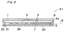
- Fig. 2 is a sectional view taken along the line II-II in Fig. 1;
- Fig. 3 is a perspective view of a magnetic recording and reproducing apparatus according to a second embodiment of the present invention; and
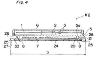
- Fig. 4 is a sectional view taken along the line IV-IV in Fig. 3.
- Before the description of the present invention proceeds, it is to be noted that like parts are designated by like reference numerals throughout several views of the accompanying drawings.
- Referring now to the drawings, there is shown in Figs. 1 and 2, a magnetic recording and reproducing apparatus K1 according to a first embodiment of the present invention. The apparatus K1 includes at least one magnetic recording and reproducing medium 1 having a diameter of about 48 mm, a
spindle motor 2 for effecting rotational drive of the medium 1 and atransducer 3 which is provided on one of opposite faces of the medium 1. At least one medium 1 is mounted on thespindle motor 2. Thus, when one medium 1 is used, twotransducers 3 should be provided, and when two media 1 are used, fourtransducers 3 should be provided. - The apparatus K1 further includes a displacement means 4, a
boxlike casing 5 and afirst cover 6. The displacement means 4 is provided for displacing thetransducer 3 to an arbitrary position on one face of the medium 1 so as to record and reproduce information on the medium 1. Thespindle motor 2 and the displacement means 4 are mounted on abottom wall 5a of thecasing 5 so as to be closed by thefirst cover 6. - Moreover, the apparatus K1 includes an
electric circuit board 7 and asecond cover 24. In thecasing 5, aboxlike space 20 is defined below thebottom wall 5a. Theelectric circuit board 7 is fitted in theboxlike space 20 so as to be attached to thecasing 5 byscrews 8 and is closed by thesecond cover 24. The apparatus K1 is secured to acomputer body 11 by using tappedholes 23 formed on abottom face 22 of aside wall 21 of thecasing 5. - Operation of the apparatus K1 of the above described arrangement is described with reference to Figs. 1 and 2. The
spindle motor 2 is usually rotated at a constant speed of about 3,600 r.p.m. so as to drive the medium 1 for its rotation. Thetransducer 3 is attached to a distal end of the displacement means 4 via aflexible support member 12 and is usually caused to hover above the face of the medium 1 through a gap of about 0.1 µm by air flow produced by rotation of the medium 1. Therefore, air in thecasing 5 is required to be kept clean. To this end, thefirst cover 6 closes thecasing 5 so as to prevent entry of outside minute dust into thecasing 5. Thetransducer 3 is positioned at an arbitrary location of a data region of the medium 1 while hovering above the face of the medium 1 such that exchange of information is performed between thetransducer 3 and the medium 1. - In the first embodiment of the present invention, since section modulus about a neutral axis B (Fig. 2) of the
casing 5 is increased by theside wall 21 defining theboxlike space 20 below thebottom wall 5a, mechanical strength of thecasing 5 rises. Thus, when theelectric circuit board 7 is attached to thecasing 5 or the apparatus K1 is mounted on thecomputer body 11, strain of thecasing 5 can be lessened. Furthermore, contact with theelectric circuit board 7 from outside is prevented by theside wall 21 and thesecond cover 24. - As described above, the
boxlike space 20 is defined below thebottom wall 5a of thecasing 5 and theelectric circuit board 7 is mounted in theboxlike space 20 so as to be closed by thesecond cover 24 in the first embodiment of the present invention. Therefore, in accordance with the first embodiment of the present invention, drop of strength of thecasing 5 due to reduction of thickness of the apparatus K1 can be avoided and theelectric circuit board 7 can be protected from outside. - In the first embodiment of the present invention, since the electric circuit board is mounted in the boxlike space defined below the bottom wall of the casing, high strength of the casing can be secured. Therefore, it is possible to reduce strain of the apparatus produced when the apparatus is mounted on a computer body. Furthermore, since the electric circuit board can be enclosed by the second cover, the electric circuit board can be protected from damage during transport or assembly of the apparatus.
- Referring further to Figs. 3 and 4, there is shown a magnetic recording and reproducing apparatus K2 according to a second embodiment of the present invention. In the
casing 5, each of a pair ofrails 25 is formed integrally at a lower end of each of opposite longitudinal side faces of theside wall 21 so as to project laterally outwardly from theside wall 21. Agroove 26 is defined between thebottom wall 5a and each of therails 25. Thegroove 26 has a width of about 1 to 2 mm and a depth of about 3 mm. Therails 25 have alower end face 27 of thecasing 5 and a height of about 3.3 mm from thelower end face 27. Aconnector 28 is provided at one end of therails 25 so as to be flush with therails 25. Therails 25 are longer than thefirst cover 6. At one end of therails 25 adjacent to theconnector 28, one of therails 25 is formed with acavity 31 having a proper length, while the other of therails 25 is formed with arecess 32 having a proper length. When thesecond cover 24 has been attached to thecasing 5, thesecond cover 24 is disposed slightly above thelower end face 27 of therails 25 such that arecessed portion 33 is formed between thesecond cover 24 and thelower end face 27 of therails 25. A pair ofguides 29 each having a substantially U-shaped cross section are provided on acomputer body 30 so as to receive therails 25, respectively. As a result, when the apparatus K1 is mounted on and detached from thecomputer body 30 through engagement of therails 25 with theguides 29 and disengagement of therails 25 from theguides 29, thesecond cover 24 is held out of contact with theguides 29. Since other constructions of the apparatus K2 are similar to those of the apparatus K1, description thereof is abbreviated for the sake of brevity. - The apparatus K2 of the above described arrangement is operated in the same manner as the apparatus K1. The apparatus K2 is characterized in that not only strength of the
casing 5 is increased but the apparatus K2 can be mounted on and detached from thecomputer body 30 by the operator himself. When the apparatus K2 is mounted on and detached from thecomputer body 30, position of the apparatus K2 in directions of height and width of thecasing 5 is regulated by engagement of therails 25 with theguides 29. - Meanwhile, in the apparatus K2, the
rails 25 are provided along thelower end face 27 of thecasing 5. However, in order to secure high strength of thecasing 5, therails 25 may not be necessarily required to be provided along thelower end face 27 of thecasing 5. - When the
rails 25 have a thickness of 3.3 mm and a span S of about 54 mm and thegroove 26 has a width of 1 to 2 mm and a depth of 3 mm or more, the apparatus K2 can be used, without the need for its modification, for a mechanism for detachably mounting an IC (integrated circuit) memory card. In this case, it is proper that diameter of the medium 1 is not more than 50 mm. - In the second embodiment of the present invention, the electric circuit board is mounted in the boxlike space defined below the bottom wall of the casing and a pair of the rails are, respectively, provided at the opposite longitudinal side faces of the side wall of the casing such that the connector is provided at one end of the rails. Therefore, the apparatus can be mounted on and detached from the computer body by the operator himself. In addition, since high strength of the casing can also be secured, the apparatus can withstand external forces or impacts applied thereto when the operator is carrying the apparatus.
Claims (5)
- A magnetic recording and reproducing apparatus comprising:
a magnetic recording and reproducing medium (1);
a spindle motor (2) for effecting rotational drive of said magnetic recording and reproducing medium (1);
a transducer (3) for recording and reproducing information on one face of said magnetic recording and reproducing medium (1);
a displacement means (4) for displacing said transducer (3) to an arbitrary radial position on the face of said magnetic recording and reproducing medium (1);
an electric circuit board (7) for processing the information and controlling said spindle motor (2) and said displacement means (4); and
a casing (5) in which said magnetic recording and reproducing medium (1), said spindle motor (2), said transducer (3), said displacement means (4) are mounted, and which casing is closed by a first cover (6);
characterized in that
said casing (5) has a bottom wall (5a) such that a boxlike space (20) is defined below said bottom wall (5a); and
said electric circuit board (7) is disposed in the boxlike space (20) which is closed by a second cover (24). - A magnetic recording and reproducing apparatus as claimed in claim 1, characterized by said casing (5) including a pair of rails (25) formed at opposite sides of said casing (5), respectively; and a connector (28) which is provided at one end of said rails (25).
- A magnetic recording and reproducing apparatus as claimed in claim 1 or 2, wherein said magnetic recording and reproducing medium (1) has a diameter of not more than 50 mm.
- A magnetic recording and reproducing apparatus as claimed in claim 2 or 3, wherein said rails (25) are provided at a lower end of said casing (5); said rails (5) having a thickness of about 3.3 mm and a span (S) of about 54 mm such that a groove (26) having a depth of not less than 3 mm is defined above each of said rails (25).
- A magnetic recording and reproducing apparatus as claimed in any one of claims 2-4, wherein said rails (25) are integrally molded with said casing (5).
Applications Claiming Priority (2)
| Application Number | Priority Date | Filing Date | Title |
|---|---|---|---|
| JP298724/91 | 1991-11-14 | ||
| JP3298724A JP2850603B2 (en) | 1991-11-14 | 1991-11-14 | Magnetic recording / reproducing device |
Publications (3)
| Publication Number | Publication Date |
|---|---|
| EP0542183A2 EP0542183A2 (en) | 1993-05-19 |
| EP0542183A3 EP0542183A3 (en) | 1993-06-30 |
| EP0542183B1 true EP0542183B1 (en) | 1995-11-02 |
Family
ID=17863459
Family Applications (1)
| Application Number | Title | Priority Date | Filing Date |
|---|---|---|---|
| EP92119176A Expired - Lifetime EP0542183B1 (en) | 1991-11-14 | 1992-11-10 | Magnetic recording and reproducing apparatus |
Country Status (4)
| Country | Link |
|---|---|
| US (1) | US5657182A (en) |
| EP (1) | EP0542183B1 (en) |
| JP (1) | JP2850603B2 (en) |
| DE (1) | DE69205799T2 (en) |
Families Citing this family (8)
| Publication number | Priority date | Publication date | Assignee | Title |
|---|---|---|---|---|
| US5488523A (en) * | 1992-05-06 | 1996-01-30 | Maxtor Corporation | Ultra-slim disk storage unit having a hydrodynamic bearing assembly which forms a stable meniscus |
| US5822152A (en) * | 1992-05-06 | 1998-10-13 | Maxtor Corporation | Ultra-slim disk storage unit with an enclosed circuit board and a hydrodynamic bearing assembly which forms a stable meniscus |
| EP0647942A1 (en) * | 1993-10-12 | 1995-04-12 | Hewlett-Packard Company | Disk drive with inverted base and method for its assembly |
| US6426847B1 (en) * | 1999-04-21 | 2002-07-30 | Seagate Technology Llc | Over-molded base plate and method of manufacture of over-molded base plate for a disc drive |
| US6735043B2 (en) | 1999-05-07 | 2004-05-11 | Seagate Technology Llc | Disc drive protective cover to improve shock robustness |
| WO2002082430A2 (en) * | 2001-04-06 | 2002-10-17 | Seagate Technology Llc | Disc drive protective cover to improve shock robustness |
| US7760464B2 (en) * | 2005-09-08 | 2010-07-20 | Seagate Technology Llc | Base for data storage device with parallelism mounting features |
| US20160291644A1 (en) * | 2015-03-30 | 2016-10-06 | Seagate Technology Llc | Base deck with carrier features |
Family Cites Families (12)
| Publication number | Priority date | Publication date | Assignee | Title |
|---|---|---|---|---|
| US4194225A (en) * | 1978-06-06 | 1980-03-18 | International Memories, Inc. | Housing for disk drive unit |
| US4317146A (en) * | 1979-12-03 | 1982-02-23 | Micropolis Corporation | Compact magnetic disk storage system |
| GB2190531B (en) * | 1986-04-23 | 1990-09-12 | Rodime Plc | Rotary voice coil actuator microhard disk drive system. |
| JPS6423795U (en) * | 1987-07-29 | 1989-02-08 | ||
| US4965684A (en) * | 1988-01-25 | 1990-10-23 | Conner Peripherals, Inc. | Low height disk drive |
| JPH01174795U (en) * | 1988-05-24 | 1989-12-12 | ||
| US4923406A (en) * | 1988-11-17 | 1990-05-08 | Magnetic Peripherals Inc. | Spindle motor flex cable |
| US5025335B1 (en) * | 1989-07-31 | 1995-12-26 | Conner Peripherals Inc | Architecture for 2 1/2 inch diameter single disk drive |
| KR100232589B1 (en) * | 1989-07-31 | 2000-01-15 | 토마스 에프.멀베니 | Disk drive |
| US5025336A (en) * | 1989-11-06 | 1991-06-18 | Prairietek Corporation | Disk drive apparatus |
| US5155662A (en) * | 1991-01-16 | 1992-10-13 | Shou Tsai I | Hard disc drive mounting structure |
| US5195022A (en) * | 1991-11-01 | 1993-03-16 | Hewlett-Packard Company | Removable mass storage module for computer systems |
-
1991
- 1991-11-14 JP JP3298724A patent/JP2850603B2/en not_active Expired - Fee Related
-
1992
- 1992-11-10 EP EP92119176A patent/EP0542183B1/en not_active Expired - Lifetime
- 1992-11-10 DE DE69205799T patent/DE69205799T2/en not_active Expired - Fee Related
- 1992-11-13 US US07/975,631 patent/US5657182A/en not_active Expired - Fee Related
Also Published As
| Publication number | Publication date |
|---|---|
| EP0542183A3 (en) | 1993-06-30 |
| US5657182A (en) | 1997-08-12 |
| JPH05135560A (en) | 1993-06-01 |
| JP2850603B2 (en) | 1999-01-27 |
| DE69205799D1 (en) | 1995-12-07 |
| DE69205799T2 (en) | 1996-06-05 |
| EP0542183A2 (en) | 1993-05-19 |
Similar Documents
| Publication | Publication Date | Title |
|---|---|---|
| US5270887A (en) | Compact disk drive head disk assembly with conformable tape seal | |
| US6304440B1 (en) | Shock-proof device of external hard disk driver box | |
| US5235481A (en) | Magnetic disk drive having a cartridge with actuator and spindle | |
| EP1731988B1 (en) | Disk unit mounting mechanism | |
| EP0534745B1 (en) | High capacity, low profile disk drive system | |
| EP0171130B1 (en) | Cartridge tape drive with improved head-positioner means | |
| US7428122B2 (en) | Hermetically sealed disk drive with low height | |
| EP0253626B1 (en) | Magnetic disc device | |
| US5596461A (en) | Space efficient housing configuration for a disk drive #7 | |
| US5936808A (en) | Disk drive rotary actuator having arm with cross-member containing elastomeric damping member | |
| EP0542183A2 (en) | Magnetic recording and reproducing apparatus | |
| EP0537707A2 (en) | Assembly of compact disk drive | |
| CA1180803A (en) | Information recording apparatus with a disc loaded in a casette | |
| US7667925B2 (en) | Hard disk drive | |
| US6243228B1 (en) | Information storage and retrieval device | |
| EP1460616B1 (en) | Head support device and disk drive using the same | |
| US6697218B2 (en) | Information storage and retrieval device | |
| US7154757B1 (en) | Media drive vibration isolation and attenuation method and apparatus | |
| JP2003314613A (en) | Vibration control structure of electronic apparatus | |
| US7379396B2 (en) | Rotary disk type storage device | |
| JP2008210454A (en) | Mounting casing for electronic device having vibration-proof structure, and electronic device mounting device for detachably mounting same | |
| US20050135001A1 (en) | Magnetic recording device | |
| JP3104516B2 (en) | Disk unit | |
| JP4185844B2 (en) | Optical disk device | |
| JPH04109485A (en) | disk device |
Legal Events
| Date | Code | Title | Description |
|---|---|---|---|
| PUAI | Public reference made under article 153(3) epc to a published international application that has entered the european phase |
Free format text: ORIGINAL CODE: 0009012 |
|
| PUAL | Search report despatched |
Free format text: ORIGINAL CODE: 0009013 |
|
| 17P | Request for examination filed |
Effective date: 19921110 |
|
| AK | Designated contracting states |
Kind code of ref document: A2 Designated state(s): DE GB IT |
|
| AK | Designated contracting states |
Kind code of ref document: A3 Designated state(s): DE GB IT |
|
| 17Q | First examination report despatched |
Effective date: 19931130 |
|
| GRAA | (expected) grant |
Free format text: ORIGINAL CODE: 0009210 |
|
| AK | Designated contracting states |
Kind code of ref document: B1 Designated state(s): DE GB IT |
|
| PG25 | Lapsed in a contracting state [announced via postgrant information from national office to epo] |
Ref country code: IT Free format text: LAPSE BECAUSE OF FAILURE TO SUBMIT A TRANSLATION OF THE DESCRIPTION OR TO PAY THE FEE WITHIN THE PRE;WARNING: LAPSES OF ITALIAN PATENTS WITH EFFECTIVE DATE BEFORE 2007 MAY HAVE OCCURRED AT ANY TIME BEFORE 2007. THE CORRECT EFFECTIVE DATE MAY BE DIFFERENT FROM THE ONE RECORDED.SCRIBED TIME-LIMIT Effective date: 19951102 |
|
| REF | Corresponds to: |
Ref document number: 69205799 Country of ref document: DE Date of ref document: 19951207 |
|
| PLBE | No opposition filed within time limit |
Free format text: ORIGINAL CODE: 0009261 |
|
| STAA | Information on the status of an ep patent application or granted ep patent |
Free format text: STATUS: NO OPPOSITION FILED WITHIN TIME LIMIT |
|
| 26N | No opposition filed | ||
| REG | Reference to a national code |
Ref country code: GB Ref legal event code: IF02 |
|
| PGFP | Annual fee paid to national office [announced via postgrant information from national office to epo] |
Ref country code: DE Payment date: 20051103 Year of fee payment: 14 |
|
| PGFP | Annual fee paid to national office [announced via postgrant information from national office to epo] |
Ref country code: GB Payment date: 20051109 Year of fee payment: 14 |
|
| PG25 | Lapsed in a contracting state [announced via postgrant information from national office to epo] |
Ref country code: DE Free format text: LAPSE BECAUSE OF NON-PAYMENT OF DUE FEES Effective date: 20070601 |
|
| GBPC | Gb: european patent ceased through non-payment of renewal fee |
Effective date: 20061110 |
|
| PG25 | Lapsed in a contracting state [announced via postgrant information from national office to epo] |
Ref country code: GB Free format text: LAPSE BECAUSE OF NON-PAYMENT OF DUE FEES Effective date: 20061110 |