EP0541672B1 - An air-humidity indicator and a method of making a humidity-sensitive strip for same - Google Patents
An air-humidity indicator and a method of making a humidity-sensitive strip for same Download PDFInfo
- Publication number
- EP0541672B1 EP0541672B1 EP19910914412 EP91914412A EP0541672B1 EP 0541672 B1 EP0541672 B1 EP 0541672B1 EP 19910914412 EP19910914412 EP 19910914412 EP 91914412 A EP91914412 A EP 91914412A EP 0541672 B1 EP0541672 B1 EP 0541672B1
- Authority
- EP
- European Patent Office
- Prior art keywords
- strip
- humidity
- tube
- indicator
- indicator according
- Prior art date
- Legal status (The legal status is an assumption and is not a legal conclusion. Google has not performed a legal analysis and makes no representation as to the accuracy of the status listed.)
- Expired - Lifetime
Links
Images
Classifications
-
- G—PHYSICS
- G01—MEASURING; TESTING
- G01N—INVESTIGATING OR ANALYSING MATERIALS BY DETERMINING THEIR CHEMICAL OR PHYSICAL PROPERTIES
- G01N19/00—Investigating materials by mechanical methods
- G01N19/10—Measuring moisture content, e.g. by measuring change in length of hygroscopic filament; Hygrometers
Definitions
- the present invention relates to an air-humidity indicator of the kind set forth in the preamble of claim 1.
- the present invention also relates to a method of producing a humidity-sensitive strip for use in an indicator according to the present invention, and this method is characterised by the steps set forth in claim 10.
- the humidity indicator shown in the drawing consists of a tube 1 made of transparent material, such as acrylic resin or the like.
- the tube 1 is open at one end, whilst the other end is closed in an air-tight and vapour-tight manner by an end wall 2, the latter preferably being integral with the tube 1.
- a paper strip 3 is secured to the end wall 2, in the example shown by being inserted through a slit in the latter and cemented to same by means of suitable cement or glue 4.
- the paper strip 3 is folded in zig-zag fashion, thus exhibiting a number of transverse folding lines 5.
- the paper strip 3 consists of a type of paper, in which the fibres adhere to each other by means of an adhesive that may be dissolved or at least softened by water, normal fine tissue paper having proved suitable. Before being inserted in the tube 1 in the manner shown in Figure 1, the paper strip 3 has been treated in the following manner:
- the open end of the tube 1 is closed in an air-tight and vapour-tight manner by means of a cap 6 cooperating sealingly with an annular sealing flange 7 made of resilient rubber or plastics material, that extends around the open end of the tube 1, said sealing flange having a peripheral sealing lip 7a.
- the humidity indicator When the humidity indicator is to be used for measuring the humidity in e.g. a concrete floor 8, of which but a tiny part is shown in Figure 3, a hole 9 is drilled into the concrete floor 8, after which the cap 6 is removed from the sealing flange 7 and the tube 1 is placed in continuation of the hole 9 as shown in Figure 3 with the sealing flange 7 with its sealing lip 7a making an air-tight and vapour-tight joint between the tube 1 and the concrete floor 8.
- the inherent elasticity of the paper fibres has proved sufficient to effect at least a partial straightening of the strip 3 when influenced by the absorbed moisture, thus providing the requisite visible effect.
- the constantly acting unfolding force may be the force of gravity, the inherent elasticity of the paper in the folding lines 5, or a force exerted by some external means (not shown).
- the paper strip 3 is tapered along straight-line edges to an end point 10. With this shape of the paper strip 3, the ratio between the length of each folding line 5 and the weight of the paper below it will be substantially constant, so that the "opening angle" will be substantially the same at all folding lines.
- fine tissue paper has proved suitable for use in making the paper strip 3, but it could also be possible to use other fibrous web materials, such as so-called cigarette paper, nonwoven fabric or the like, two essential conditions being
- the following table shows examples of relatively harmless hygroscopic salts that may be used as the hygroscopic substance, with which the paper strip 3 is impregnated.
- a cartridge or bag containing a drying agent such as silica gel
- a drying agent such as silica gel
- an air-tight and vapour-tight container also containing a suitably dimensioned portion of such drying agent.
- the paper strip 3 may have any suitable size, but is preferably about 1.5 mm wide, narrowing to zero at the end point 10, in which case it is preferably about 20 mm long. If so, the total length of the tube 1 with cap 6 would be about 13 mm and the insertion diameter of the sealing flange 7 about 5 mm, thus requiring a test hole 9 of only 5 mm in diameter.
Landscapes
- Physics & Mathematics (AREA)
- Health & Medical Sciences (AREA)
- Life Sciences & Earth Sciences (AREA)
- Chemical & Material Sciences (AREA)
- Analytical Chemistry (AREA)
- Biochemistry (AREA)
- General Health & Medical Sciences (AREA)
- General Physics & Mathematics (AREA)
- Immunology (AREA)
- Pathology (AREA)
- Investigating Or Analyzing Non-Biological Materials By The Use Of Chemical Means (AREA)
- Drying Of Gases (AREA)
Abstract
Description
- The present invention relates to an air-humidity indicator of the kind set forth in the preamble of
claim 1. - In indicators of this kind, it is known to utilize the ability of the hygroscopic substance to absorb water from the air to obtain various visible effects, such as a change of colour of a carrier substance or a change in electrical conductivity. These effects are not always convenient to use, especially when measuring the relative humidity at a great number of points in a building structure, such as a concrete floor, where it is necessary to ascertain the degree of relative humidity in order to determine whether the material in question is suitable for receiving glue or cement used for securing a covering, such as a fixed carpet or linoleum, to the structure. Thus, the relatively large number of indicators necessary will often make the process of examining the relative humidity mentioned prohibitively costly, and in other cases difficulties may arise in interpreting the visual effects observed, especially when using colour changes.
- It is the object of the present invention to provide an air-humidity indicator of the kind referred to initially, that may be produced at a very low cost, while the visual effects are easy to observe and interpret, and this object is achieved with an air-humidity indicator of the kind referred to above, which according to the present invention is characterised by the features set forth in
claim 1. - With this arrangement, the moisture absorbed from the air by the hygroscopic substance will weaken the fold or folds, so that the constantly acting force will straighten or unfold the strip in an easily observable manner.
- Advantageous embodiments of the indicator according to the present invention, the effects of which are explained in the following detailed portion of the present specification, are set forth in claims 2-9.
- The present invention also relates to a method of producing a humidity-sensitive strip for use in an indicator according to the present invention, and this method is characterised by the steps set forth in
claim 10. - In the following detailed specification, the present invention will be explained in more detail with reference to the exemplary embodiment of a humidity indicator shown in the drawing, in which
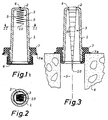
- Figure 1 is a longitudinal sectional view through the indicator in its state before use, carrying a protective cap,
- Figure 2 is a cross-sectional view taken along the line II-II in Figure 1, and
- Figure 3 is a longitudinal sectional view of the indicator in use for determining the relative humidity in a concrete floor, said section being taken along a plane at right angles to the sectional plane of Figure 1.
- The humidity indicator shown in the drawing consists of a
tube 1 made of transparent material, such as acrylic resin or the like. Thetube 1 is open at one end, whilst the other end is closed in an air-tight and vapour-tight manner by anend wall 2, the latter preferably being integral with thetube 1. - A
paper strip 3 is secured to theend wall 2, in the example shown by being inserted through a slit in the latter and cemented to same by means of suitable cement orglue 4. Thepaper strip 3 is folded in zig-zag fashion, thus exhibiting a number oftransverse folding lines 5. - The
paper strip 3 consists of a type of paper, in which the fibres adhere to each other by means of an adhesive that may be dissolved or at least softened by water, normal fine tissue paper having proved suitable. Before being inserted in thetube 1 in the manner shown in Figure 1, thepaper strip 3 has been treated in the following manner: - first, the paper strip or the material, from which it is made, is impregnated with a solution of a hygroscopic substance capable of absorbing water from the air having at least a predetermined degree of humidity, after which the paper is dried before the impregnating solution has dissolved the adhesive holding the fibres together,
- the paper thus having been impregnated and dried is folded in zig-zag fashion in the manner indicated in Figure 1,
- the paper being cut into strips at some suitable time before, during or after the above impregnating, drying and folding steps.
- As soon as the impregnated, dried and zig-zag folded
paper strip 3 has been placed in thetube 1 in the position shown in Figure 1 and secured to theend wall 2, the open end of thetube 1 is closed in an air-tight and vapour-tight manner by means of acap 6 cooperating sealingly with anannular sealing flange 7 made of resilient rubber or plastics material, that extends around the open end of thetube 1, said sealing flange having aperipheral sealing lip 7a. - When the humidity indicator is to be used for measuring the humidity in e.g. a
concrete floor 8, of which but a tiny part is shown in Figure 3, ahole 9 is drilled into theconcrete floor 8, after which thecap 6 is removed from the sealingflange 7 and thetube 1 is placed in continuation of thehole 9 as shown in Figure 3 with thesealing flange 7 with itssealing lip 7a making an air-tight and vapour-tight joint between thetube 1 and theconcrete floor 8. - After a short period of time, a humidity equilibrium will be established between the space in the
hole 9 and the space in thetube 1, and if the degree of humidity is sufficient to liquefy the hygroscopic substance, with which thepaper strip 3 has been impregnated, water will be absorbed from the atmosphere inside thetube 1 and soften or dissolve the adhesive holding the fibres of thepaper strip 3 together, thus reducing the bending strength of the paper at thefolding lines 5 to such an extent, that the mere weight of the paper strip and of the water having been absorbed will cause thepaper strip 3 to unfold at least partly as shown in Figure 3, thus clearly indicating to an observer that the humidity in the region of the concrete floor around thehole 9 is equal to or exceeds the liquefaction threshold for the hygroscopic substance being used. In cases where thetest hole 9 is more or less horizontal instead of vertical as shown in Figure 3, the inherent elasticity of the paper fibres has proved sufficient to effect at least a partial straightening of thestrip 3 when influenced by the absorbed moisture, thus providing the requisite visible effect. Thus, the constantly acting unfolding force may be the force of gravity, the inherent elasticity of the paper in thefolding lines 5, or a force exerted by some external means (not shown). - At shown in Figure 3, the
paper strip 3 is tapered along straight-line edges to anend point 10. With this shape of thepaper strip 3, the ratio between the length of eachfolding line 5 and the weight of the paper below it will be substantially constant, so that the "opening angle" will be substantially the same at all folding lines. - As mentioned above, fine tissue paper has proved suitable for use in making the
paper strip 3, but it could also be possible to use other fibrous web materials, such as so-called cigarette paper, nonwoven fabric or the like, two essential conditions being - that the adhesive holding the fibres together may be dissolved or softened by water, and
- that the material is sufficiently thin to unfold at least partly, when said adhesive is being dissolved or softened by moisture having been absorbed by the hygroscopic substance.
- The following table shows examples of relatively harmless hygroscopic salts that may be used as the hygroscopic substance, with which the
paper strip 3 is impregnated.
- If the humidity indicator made ready for use as shown in Figure 1 is to be stored for a considerable length of time before use, a cartridge or bag containing a drying agent, such as silica gel, may be placed inside the
tube 1 before closing it with acap 6. Another possibility is to place the whole humidity indicator, either singly or in a small or large number, in an air-tight and vapour-tight container also containing a suitably dimensioned portion of such drying agent. In the first-mentioned case, in which a drying agent is placed inside thetube 1, care should be taken to avoid the drying agent contacting thepaper strip 3; this could suitably be achieved by securing the cartridge or bag containing the drying agent to the inside of thecap 6. - The
paper strip 3 may have any suitable size, but is preferably about 1.5 mm wide, narrowing to zero at theend point 10, in which case it is preferably about 20 mm long. If so, the total length of thetube 1 withcap 6 would be about 13 mm and the insertion diameter of thesealing flange 7 about 5 mm, thus requiring atest hole 9 of only 5 mm in diameter.
Claims (10)
- An air-humidity indicator of the kind, in which the effect is based on a hygroscopic substance, which when acted upon by air with at least a predetermined degree of humidity absorbs water from the air and is dissolved in said water, characterized in that said hygroscopic substance is carried by a strip (3) of fibrous web material, e.g. paper, in which the fibres adhere to each other by means of an adhesive, that may be dissolved or softened by water, said strip (3) being secured (4) solely at one of its ends or edges and comprising at least one sharp fold (5) between said end or edge and the opposite, free end or edge (10), said fold or folds (5) at least in the operative position of the indicator being acted upon by a force acting constantly in the unfolding direction.
- An indicator according to claim 1, characterized in that the fibrous material is fine tissue paper, cigarette paper or the like.
- An indicator according to claim 1 or 2, characterized in that said hygroscopic substance is selected from the group of salts comprising anhydrous copper chloride, dihydrate of copper chloride, sodium chloride, ammonium sulphate, potassium chloride, potassium nitrate and potassium sulphate.
- An indicator according to any one or any of the claims 1-3, characterized in that the strip (3) with one of its ends or edges is secured to the inside of an end wall (2) or side wall of an at least partly transparent container (1), the length or width of which is of the same order of magnitude as the length or width respectively of the strip in the unfolded state of the latter.
- An indicator according to claim 4, characterized in that said container (1) is formed as a tube closed at one end, in which one end of the strip (3) is secured to the inside of the closed end (2) of the tube.
- An indicator according to claim 5, characterized in that said strip (3) is tapered, being secured at its widest end.
- An indicator according to claim 6, characterized in that the strip (3) tapers to a point at its free end (10).
- An indicator according to any one or any of the claims 5-7, characterized by an annular gasket or seal (7) placed on the outside of the tube at or adjacent to the latter's open end, said gasket or seal having such a shape, that when the tube is inserted in a circular opening (9) in e.g. a concrete floor (8), it seals the tube against the wall of the opening and/or the external surface of said floor (8).
- An indicator according to any one or any of the claims 1-8, characterized in that it is adapted to be sealed in an airtight manner from the surroundings, either by the container (1) being provided with a removable, moisture-proof seal (6), or by the container (1) being placed in a moisture-proof bag, package or container, which may be opened without damaging the humidity indicator, and that may contain a drying agent, e.g. silica gel.
- A method of producing a humidity-sensitive strip (3) for use in an indicator according to any one or any of the claims 1-9, characterized by the following steps a-c:a) fibrous web material, e.g. paper, of a kind in which the fibres adhere to each other by means of an adhesive, that may be dissolved or softened by water, is immersed in a solution of a hygroscopic substance of the kind, which when acted upon in its dry state by air with at least a predetermined degree of humidity absorbs water from the air and is dissolved in said water, said immersion being carried out for a length of time sufficient for said solution to impregnate said fibrous material but insufficient for said solution to dissolve said adhesive to a substantial extent, after which the fibrous material is dried, andb) the impregnated and dried fibrous material is folded along at least one folding line, whereasc) the fibrous material is cut into strip form at any time before, during or after the steps set forth in items a and b above.
Priority Applications (1)
| Application Number | Priority Date | Filing Date | Title |
|---|---|---|---|
| AT91914412T ATE101437T1 (en) | 1990-07-31 | 1991-07-26 | HUMIDITY INDICATORS AND METHOD OF MANUFACTURE OF A HUMIDITY SENSITIVE STRIP THEREOF. |
Applications Claiming Priority (2)
| Application Number | Priority Date | Filing Date | Title |
|---|---|---|---|
| DK182590A DK167369B1 (en) | 1990-07-31 | 1990-07-31 | HUMIDITY INDICATOR FOR DETERMINING THE DEFINITION OF THE MOISTURE IN A BUILDING PART, AND PROCEDURE FOR THE MANUFACTURING OF ANY SPECIFIED HUMIDITY SENSITIVE STRIP |
| DK1825/90 | 1990-07-31 |
Publications (2)
| Publication Number | Publication Date |
|---|---|
| EP0541672A1 EP0541672A1 (en) | 1993-05-19 |
| EP0541672B1 true EP0541672B1 (en) | 1994-02-09 |
Family
ID=8108326
Family Applications (1)
| Application Number | Title | Priority Date | Filing Date |
|---|---|---|---|
| EP19910914412 Expired - Lifetime EP0541672B1 (en) | 1990-07-31 | 1991-07-26 | An air-humidity indicator and a method of making a humidity-sensitive strip for same |
Country Status (5)
| Country | Link |
|---|---|
| EP (1) | EP0541672B1 (en) |
| AU (1) | AU8320391A (en) |
| DE (1) | DE69101158T2 (en) |
| DK (1) | DK167369B1 (en) |
| WO (1) | WO1992002801A1 (en) |
Families Citing this family (3)
| Publication number | Priority date | Publication date | Assignee | Title |
|---|---|---|---|---|
| IT1313584B1 (en) * | 1999-07-30 | 2002-09-09 | Levosil S P A | HUMIDITY INDICATORS TO INDICATE THE ABSORBING CAPACITY OF A DEHYDRATING MATERIAL. |
| IT1319669B1 (en) * | 2000-12-01 | 2003-10-23 | Levosil S P A | PAPER HUMIDITY INDICATORS WITH COLORED SUPPORT. |
| AT517846B1 (en) * | 2015-12-14 | 2017-05-15 | Univ Wien Tech | Indicator device for building material moisture determination |
Family Cites Families (2)
| Publication number | Priority date | Publication date | Assignee | Title |
|---|---|---|---|---|
| DE179706C (en) * | ||||
| US2534279A (en) * | 1947-07-26 | 1950-12-19 | Sonneborn Sons Inc L | Vapor detecting device for determining paintability of masonry surfaces |
-
1990
- 1990-07-31 DK DK182590A patent/DK167369B1/en not_active IP Right Cessation
-
1991
- 1991-07-26 DE DE69101158T patent/DE69101158T2/en not_active Expired - Fee Related
- 1991-07-26 AU AU83203/91A patent/AU8320391A/en not_active Abandoned
- 1991-07-26 EP EP19910914412 patent/EP0541672B1/en not_active Expired - Lifetime
- 1991-07-26 WO PCT/DK1991/000216 patent/WO1992002801A1/en not_active Ceased
Also Published As
| Publication number | Publication date |
|---|---|
| DK167369B1 (en) | 1993-10-18 |
| DE69101158T2 (en) | 1994-09-08 |
| EP0541672A1 (en) | 1993-05-19 |
| DK182590A (en) | 1992-02-01 |
| WO1992002801A1 (en) | 1992-02-20 |
| DE69101158D1 (en) | 1994-03-24 |
| AU8320391A (en) | 1992-03-02 |
| DK182590D0 (en) | 1990-07-31 |
Similar Documents
| Publication | Publication Date | Title |
|---|---|---|
| US4220244A (en) | Fresh face pad | |
| US4013099A (en) | Sheathed tubular stick | |
| BR9815692A (en) | Dehumidifying pouch | |
| AR220388A1 (en) | TEST STRIP FOR THE EVALUATION OF DISSOLVED SUBSTANCES IN AQUEOUS SOLUTIONS AND PROCEDURE | |
| US3398826A (en) | Narrow fold moist towelette package | |
| ATE117265T1 (en) | DISPENSING CONTAINER AND METHOD FOR PRODUCING THE SAME. | |
| AU614534B2 (en) | Quadrangular shaped container for fluids | |
| PT653639E (en) | ANALYTICAL EQUIPMENT AND METHODS FOR THEIR UTILIZATION | |
| IN167315B (en) | ||
| GB9814631D0 (en) | Test strips for the determination of the ionic strength or specific gravity of an aqueous sample | |
| GB1026452A (en) | Improvements in or relating to indicating devices | |
| BR9506222A (en) | Complete drying screen for use in the paper machine drying part and process for making drying screen | |
| BR9903965A (en) | Damp fabric product. | |
| BR8500086A (en) | WASHER FOR THE WASHING OR SEPARATION OF PLASTIC FILM FROM PAPER OR CELLULOSE FIBERS OR OTHER CONTAMINANTS AND CORRESPONDING PROCEDURE | |
| WO1992002801A1 (en) | An air-humidity indicator and a method of making a humidity-sensitive strip for same | |
| CA2138445C (en) | A method for the deacidification of papers and books | |
| EP0121966A1 (en) | Sanitary towel, throw-away napkin or similar object, with improved sanitary properties | |
| IL58545A (en) | Composition,test device and method for determining the ionic strength or specific gravity of a liquid sample | |
| BR7902892A (en) | PROCESS AND DEVICE FOR HANGING LARGE BAGS IN THE FILLING FUNCTION OF A BAG FILLING DEVICE | |
| FI844106A0 (en) | SLOW FORMULATION OF OVER FLACKFOLIE FOER DESS FRAMSTAELLNING. | |
| JP2543837B2 (en) | Humidity indicator | |
| JPH0579942B2 (en) | ||
| WO1992002804A1 (en) | A humidity indicator with an encapsulated sensor | |
| CN217878448U (en) | Liquid sample collecting device | |
| SE8605356L (en) | PACKAGING FOR A FILM OR SIMILAR |
Legal Events
| Date | Code | Title | Description |
|---|---|---|---|
| PUAI | Public reference made under article 153(3) epc to a published international application that has entered the european phase |
Free format text: ORIGINAL CODE: 0009012 |
|
| 17P | Request for examination filed |
Effective date: 19930127 |
|
| AK | Designated contracting states |
Kind code of ref document: A1 Designated state(s): AT BE CH DE DK ES FR GB GR IT LI LU NL SE |
|
| 17Q | First examination report despatched |
Effective date: 19930629 |
|
| GRAA | (expected) grant |
Free format text: ORIGINAL CODE: 0009210 |
|
| AK | Designated contracting states |
Kind code of ref document: B1 Designated state(s): AT BE CH DE DK ES FR GB GR IT LI LU NL SE |
|
| PG25 | Lapsed in a contracting state [announced via postgrant information from national office to epo] |
Ref country code: IT Free format text: LAPSE BECAUSE OF FAILURE TO SUBMIT A TRANSLATION OF THE DESCRIPTION OR TO PAY THE FEE WITHIN THE PRESCRIBED TIME-LIMIT;WARNING: LAPSES OF ITALIAN PATENTS WITH EFFECTIVE DATE BEFORE 2007 MAY HAVE OCCURRED AT ANY TIME BEFORE 2007. THE CORRECT EFFECTIVE DATE MAY BE DIFFERENT FROM THE ONE RECORDED. Effective date: 19940209 Ref country code: ES Free format text: THE PATENT HAS BEEN ANNULLED BY A DECISION OF A NATIONAL AUTHORITY Effective date: 19940209 Ref country code: NL Effective date: 19940209 Ref country code: SE Effective date: 19940209 Ref country code: LI Effective date: 19940209 Ref country code: GR Free format text: LAPSE BECAUSE OF FAILURE TO SUBMIT A TRANSLATION OF THE DESCRIPTION OR TO PAY THE FEE WITHIN THE PRESCRIBED TIME-LIMIT Effective date: 19940209 Ref country code: FR Free format text: THE PATENT HAS BEEN ANNULLED BY A DECISION OF A NATIONAL AUTHORITY Effective date: 19940209 Ref country code: DK Effective date: 19940209 Ref country code: CH Effective date: 19940209 Ref country code: BE Effective date: 19940209 Ref country code: AT Effective date: 19940209 |
|
| REF | Corresponds to: |
Ref document number: 101437 Country of ref document: AT Date of ref document: 19940215 Kind code of ref document: T |
|
| REF | Corresponds to: |
Ref document number: 69101158 Country of ref document: DE Date of ref document: 19940324 |
|
| REG | Reference to a national code |
Ref country code: CH Ref legal event code: PL |
|
| EN | Fr: translation not filed | ||
| PG25 | Lapsed in a contracting state [announced via postgrant information from national office to epo] |
Ref country code: LU Free format text: LAPSE BECAUSE OF NON-PAYMENT OF DUE FEES Effective date: 19940731 |
|
| NLV1 | Nl: lapsed or annulled due to failure to fulfill the requirements of art. 29p and 29m of the patents act | ||
| PLBE | No opposition filed within time limit |
Free format text: ORIGINAL CODE: 0009261 |
|
| STAA | Information on the status of an ep patent application or granted ep patent |
Free format text: STATUS: NO OPPOSITION FILED WITHIN TIME LIMIT |
|
| 26N | No opposition filed | ||
| PG25 | Lapsed in a contracting state [announced via postgrant information from national office to epo] |
Ref country code: GB Effective date: 19950726 |
|
| GBPC | Gb: european patent ceased through non-payment of renewal fee |
Effective date: 19950726 |
|
| PGFP | Annual fee paid to national office [announced via postgrant information from national office to epo] |
Ref country code: DE Payment date: 19970729 Year of fee payment: 7 |
|
| PG25 | Lapsed in a contracting state [announced via postgrant information from national office to epo] |
Ref country code: DE Free format text: LAPSE BECAUSE OF NON-PAYMENT OF DUE FEES Effective date: 19990501 |