EP0541253B1 - Current mode hysteresis controller for pulse width modulated inverter - Google Patents
Current mode hysteresis controller for pulse width modulated inverter Download PDFInfo
- Publication number
- EP0541253B1 EP0541253B1 EP92309280A EP92309280A EP0541253B1 EP 0541253 B1 EP0541253 B1 EP 0541253B1 EP 92309280 A EP92309280 A EP 92309280A EP 92309280 A EP92309280 A EP 92309280A EP 0541253 B1 EP0541253 B1 EP 0541253B1
- Authority
- EP
- European Patent Office
- Prior art keywords
- hysteresis
- current
- error signals
- comparing
- inverter
- Prior art date
- Legal status (The legal status is an assumption and is not a legal conclusion. Google has not performed a legal analysis and makes no representation as to the accuracy of the status listed.)
- Expired - Lifetime
Links
Images



Classifications
-
- H—ELECTRICITY
- H02—GENERATION; CONVERSION OR DISTRIBUTION OF ELECTRIC POWER
- H02M—APPARATUS FOR CONVERSION BETWEEN AC AND AC, BETWEEN AC AND DC, OR BETWEEN DC AND DC, AND FOR USE WITH MAINS OR SIMILAR POWER SUPPLY SYSTEMS; CONVERSION OF DC OR AC INPUT POWER INTO SURGE OUTPUT POWER; CONTROL OR REGULATION THEREOF
- H02M7/00—Conversion of AC power input into DC power output; Conversion of DC power input into AC power output
- H02M7/42—Conversion of DC power input into AC power output without possibility of reversal
- H02M7/44—Conversion of DC power input into AC power output without possibility of reversal by static converters
- H02M7/48—Conversion of DC power input into AC power output without possibility of reversal by static converters using discharge tubes with control electrode or semiconductor devices with control electrode
- H02M7/53—Conversion of DC power input into AC power output without possibility of reversal by static converters using discharge tubes with control electrode or semiconductor devices with control electrode using devices of a triode or transistor type requiring continuous application of a control signal
- H02M7/537—Conversion of DC power input into AC power output without possibility of reversal by static converters using discharge tubes with control electrode or semiconductor devices with control electrode using devices of a triode or transistor type requiring continuous application of a control signal using semiconductor devices only, e.g. single switched pulse inverters
- H02M7/539—Conversion of DC power input into AC power output without possibility of reversal by static converters using discharge tubes with control electrode or semiconductor devices with control electrode using devices of a triode or transistor type requiring continuous application of a control signal using semiconductor devices only, e.g. single switched pulse inverters with automatic control of output wave form or frequency
- H02M7/5395—Conversion of DC power input into AC power output without possibility of reversal by static converters using discharge tubes with control electrode or semiconductor devices with control electrode using devices of a triode or transistor type requiring continuous application of a control signal using semiconductor devices only, e.g. single switched pulse inverters with automatic control of output wave form or frequency by pulse-width modulation
-
- H—ELECTRICITY
- H02—GENERATION; CONVERSION OR DISTRIBUTION OF ELECTRIC POWER
- H02P—CONTROL OR REGULATION OF ELECTRIC MOTORS, ELECTRIC GENERATORS OR DYNAMO-ELECTRIC CONVERTERS; CONTROLLING TRANSFORMERS, REACTORS OR CHOKE COILS
- H02P27/00—Arrangements or methods for the control of AC motors characterised by the kind of supply voltage
- H02P27/04—Arrangements or methods for the control of AC motors characterised by the kind of supply voltage using variable-frequency supply voltage, e.g. inverter or converter supply voltage
- H02P27/06—Arrangements or methods for the control of AC motors characterised by the kind of supply voltage using variable-frequency supply voltage, e.g. inverter or converter supply voltage using DC to AC converters or inverters
- H02P27/08—Arrangements or methods for the control of AC motors characterised by the kind of supply voltage using variable-frequency supply voltage, e.g. inverter or converter supply voltage using DC to AC converters or inverters with pulse width modulation
- H02P27/10—Arrangements or methods for the control of AC motors characterised by the kind of supply voltage using variable-frequency supply voltage, e.g. inverter or converter supply voltage using DC to AC converters or inverters with pulse width modulation using bang-bang controllers
Definitions
- a method of operating a current mode hysteresis controller for controlling a pulse width inverter in response to desired and sensed inverter output currents comprises the steps of;
- the field oriented controller 110 also receives data from a rotor position sensor 114 which may comprise, for example, an optical encoder. Finally, the field oriented controller 110 senses the currents in the individual windings of the motor 102. Although only the currents I A and I B are shown as being sensed directly, with the third current, I C , being derived from currents I A and I B by a summer or comparator 116 as the negative of the sum of I A and I B , those skilled in the art will appreciate that it is possible to directly measure all three of the phase currents as an alternative to the use of the comparator 116.
- the field oriented controller 110 calculates the desired phase currents I A *, I B *, and I C *. These desired or idealised phase currents are compared by means of comparators 118 to each of the measured phase currents I A , I B , and I C , respectively. The error for each current is then fed to current mode controllers 120.
- the current mode controllers 120 switch phase currents on and off to provide a predetermined hysteretic current level around the desired phase currents I A *, I B *, and I C *.
- the outputs of the current mode controllers 120 are fed to drivers 122, which supply gate charges for the purpose of switching transistors S1-S6.
- the desired inverter output current I ⁇ * is differentially received and amplified by an amplifier 202 to reduce common mode noise before being passed to the amplifier 200.
- the sensed inverter output current I ⁇ is similarly differentially received and amplified by an amplifier 204 to also reduce common mode noise.
- An amplifier 206 is provided to rescale the sensed inverter output current relative to a precision reference voltage V REF and pass the resulting output signal to the amplifier 200.
Landscapes
- Engineering & Computer Science (AREA)
- Power Engineering (AREA)
- Control Of Ac Motors In General (AREA)
- Inverter Devices (AREA)
Description
- The present invention relates generally to current mode hysteresis controllers used, for example, to control alternating current (AC) motors that are powered through static inverters by direct current (DC) power sources such as batteries or rectified AC power and, more particularly, to current band control within such controllers. While the present invention is generally applicable to controlling inverters for example to drive single phase motors and two phase motors, it will be described herein with reference to the control of a three phase motor for which it is being initially applied.
- AC motors in comparison to DC motors are generally of simpler structure and include advantages of lower cost, more compact size, less weight and operation at higher speeds and efficiencies. However, controllers for AC motors have been complex and expensive which has hampered the adoption of AC motors for use with DC supplies such as batteries and in particular for applications in motor vehicles. Simplification of AC motor controllers has resulted from the use of current mode controllers.
- For current mode control, the current flowing into motor terminals is measured and compared to reference current signals which are generated by a motor controller and are representative of desired current for the motor to effect desired operating conditions. Error signals resulting from the comparison are used to switch semiconductor elements of an inverter circuit which provides power to the motor. Pulse width modulated (PWM) DC power is thus rapidly switched to the terminals of the motor.
- One popular form of current mode control uses hysteresis comparators. In hysteresis current mode control, the actual currents within a motor are maintained within a band of given amplitude centred on reference currents which are representative of desired current levels within the motor. An example of hysteresis current mode control for use in a motor vehicle and in particular to control an electrically powered active suspension for a vehicle is disclosed in U.S. Patent No. 5,027,048 which issued to Masrur et al on June 25, 1991, is assigned to Ford Motor Company and is incorporated herein by reference. The hysteresis motor controller of the Masrur et al patent also discloses use of field oriented control which is another important improvement in the control of AC motors.
- A problem encountered in hysteresis current mode control is the selection of the hysteresis band. The bandwidth of the hysteresis band is selected to provide adequate control of the current level and also to minimise inverter losses. For steady-state operation at current levels greater than the hysteresis band, selection of the bandwidth is no problem. However, if current levels vary, a compromise selection must be made. Even for a compromise bandwidth, in applications such as an active suspension, reference current levels can frequently go below the hysteresis band such that the inverter is coasting, modulation disappears and road disturbances are not compensated by the suspension system.
- Accordingly, there is a need for an improved current mode hysteresis controller to substantially reduce inverter coasting while still providing high efficiency tightly controlled system operation.
- This need is met by the method and apparatus of the present invention wherein a current mode hysteresis controller is provided with selectable hysteresis bands based on the level of current to be provided. While multiple hysteresis bands can be provided for the present invention by directly selecting the upper and lower limits of the bands, it is preferred to provide a selected upper limit and a selected lower limit with hysteresis band switching being performed by selecting the amplification factor of error signals used to control the current mode hysteresis controller.
- In accordance with the present invention, a current mode hysteresis controller for controlling a pulse width modulated inverter in response to desired and sensed inverter output signals comprises;
- first comparator means for comparing said desired and sensed inverter output currents to one another to generate error signals representative of the difference therebetween;
- second comparator means for receiving said error signals and comparing them to upper and lower limits of a selected hysteresis band, said second comparator means switching the state of an output signal whenever said error signals reach the boundaries of said selected hysteresis band;
- characterised in that the controller further comprises; current band means in the form of a selectable gain amplifier for receiving and amplifying said error signals by a gain selectable to define at least two hysteresis bands for said second comparator means;
- and third comparator means for receiving the desired inverter output current and generating a hysteresis switch signal to select the gain of the amplifier based on a comparison of the desired inverter output current with a switch reference current.
- In accordance with another aspect of the invention, a method of operating a current mode hysteresis controller for controlling a pulse width inverter in response to desired and sensed inverter output currents comprises the steps of;
- comparing, in a first comparing step, the desired and sensed inverter output currents to one another to generate error signals representative of the difference therebetween;
- comparing, in a second comparing step, the error signals to upper and lower limits of a selected hysteresis band and switching the state of an output signal whenever said error signals reach the boundaries of the selected hysteresis band;
- characterised in that the method further comprises the steps of;
- amplifying said error signals by a gain which is selectable to define at least two hysteresis bands for the second comparing step;
- and comparing, in a third comparing step, the desired inverter output current with a switch reference current to generate therefrom a hysteresis switch signal for selecting the gain of the amplification of the error signals.
- The invention will now be described further, by way of example, with reference to the accompanying drawings, in which:
- Fig. 1 is a schematic block diagram of an electronic power controller used in an electrically powered active suspension system of the prior art;
- Fig. 2 is a schematic diagram of one phase of the current band control of the electronic power controller of Fig. 1 modified to operate in accordance with the present invention; and
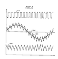
- Figs. 3 and 4 are waveforms illustrating operation of an electronic power controller operating with two different hysteresis bands in accordance with the present invention.
- While a current mode hysteresis controller operable in accordance with the present invention is generally applicable for use in controlling inverters, it will be described herein with reference to the control of a three phase inverter which in turn controls a three phase AC motor. In particular, the current mode hysteresis controller of the present invention will be described relative to control of three phase AC motors used in an electrically powered active suspension system. Fig. 1 is a schematic block diagram of an
AC motor controller 100 used in a prior art electrically powered active suspension system as disclosed in referenced U.S. Patent No. 5,027,048. One of the AC motor controllers shown in Fig. 1 is used for controlling suspension units for each of the wheels of a motor vehicle. - A centralised system controller (not shown) in the motor vehicle generates force commands for each of the wheels of the vehicle, such as the force command Fc shown in Fig. 1. The
AC motor controller 100 must then supply the correct phase currents toAC motor 102, so as to produce the forces specified by the force command Fc. A summer orcomparator 104 receives the force command Fc from the centralised system controller and adds it to or in other words, compares it with Fdev. As shown in Fig. 1, Fdev is a measured force output derived fromload cells comparator 104 is sent to a field oriented controller 110 which calculates appropriate phase currents to feed to each of the threephase legs 112 which supply the phase currents to themotor 102. - The field oriented controller 110 also receives data from a
rotor position sensor 114 which may comprise, for example, an optical encoder. Finally, the field oriented controller 110 senses the currents in the individual windings of themotor 102. Although only the currents IA and IB are shown as being sensed directly, with the third current, IC, being derived from currents IA and IB by a summer orcomparator 116 as the negative of the sum of IA and IB, those skilled in the art will appreciate that it is possible to directly measure all three of the phase currents as an alternative to the use of thecomparator 116. - The field oriented controller 110 calculates the desired phase currents IA*, IB*, and IC*. These desired or idealised phase currents are compared by means of
comparators 118 to each of the measured phase currents IA, IB, and IC, respectively. The error for each current is then fed tocurrent mode controllers 120. Thecurrent mode controllers 120 switch phase currents on and off to provide a predetermined hysteretic current level around the desired phase currents IA*, IB*, and IC*. The outputs of thecurrent mode controllers 120 are fed todrivers 122, which supply gate charges for the purpose of switching transistors S1-S6. The transistors S1 and S2, S3 and S4, S5 and S6, which are labelled 112 in Fig. 1, comprise, respectively, phase legs for supplying three separate phase currents from analternator 124 and/or capacitor 126 to themotor 102. The outputs of the phase legs are fed directly to themotor 102. For additional information regarding operation of theAC motor controller 100 or the suspension system into which it is incorporated, the reader is referred to US-A-5,027,048. - A problem is encountered in
AC motor controller 100 in terms of the hysteresis band utilised by thecurrent mode controllers 120. The bandwidth of the hysteresis band is defined to provide adequate control of the current level and also to minimise inverter losses. Unfortunately, for applications such as the disclosed active suspension system for a motor vehicle, desired motor current levels vary drastically over a range from 0 current to maximum current for theAC motor 102 such that reference current levels frequently go below the hysteresis band appropriate for high current level operation. Under these conditions, the inverter made up by the transistors S1 and S2, S3 and S4, S5 and S6 coasts, modulation disappears and road disturbances are momentarily not compensated by the suspension system. - To overcome this problem in accordance with the present invention, the
current mode controllers 120 are replaced by current mode controllers which include current band control means to define at least two hysteresis bands for thecurrent band controllers 120. In Fig. 2, onecurrent mode controller 120 of Fig. 1 is shown modified to operate in accordance with the present invention to select one of at least two hysteresis bands for the phase current Iφ to be controlled. As shown in Fig. 2, thecomparators 118 each include first comparator means comprising anoperational amplifier 200 which sums or compares the desired inverter output current Iφ* for the corresponding phase, i.e. the desired phase current for themotor 102, with the sensed inverter output current Iφ , i.e. the sensed phase current for themotor 102, to generate error signals representative of the difference therebetween. The desired inverter output current Iφ* is differentially received and amplified by anamplifier 202 to reduce common mode noise before being passed to theamplifier 200. The sensed inverter output current Iφ is similarly differentially received and amplified by anamplifier 204 to also reduce common mode noise. Anamplifier 206 is provided to rescale the sensed inverter output current relative to a precision reference voltage VREF and pass the resulting output signal to theamplifier 200. - The error signals from the
amplifier 200 are passed to current band control means comprising anamplifier 208 which amplifies the error signals by an amplification factor determined byresistors amplifier 208 defines the hysteresis band selected in accordance with the illustrated embodiment since upper and lower signal limits for the amplified error signals are determined by second comparator means comprising acomparator 216. While the upper and lower signal limits for the hysteresis bands could be directly selected, as will be apparent to those skilled in the art, it simplifies the resulting circuitry to control the amplification of the error signals and compare the resulting amplified error signals to fixed upper and lower signal limits to define at least two hysteresis bands. In any event, the amplification factor of theamplifier 208 is selectively controlled by means of atransistor 218 which is controlled via a hysteresis switch (HSW1) signal applied through aresistor 220. - In the case of two hysteresis bands, the amplification factor of the
amplifier 208 is selected based on the desired inverter output current Iφ* for the corresponding phase or the reference current for that phase. The selection in this case can be performed by acomparator 222 which sums or compares the desired inverter output current Iφ * with a signal representative of a desired switch reference current IREF. Thus, thetransistor 218 determines whether theresistor 214 is connected into the gain control circuit for theamplifier 208 or is shorted out and not included in determining the gain. While two hysteresis bands will substantially improve the operation of theAC motor controller 100, it may be desirable for this or other applications to provide more than two hysteresis bands. For operation with more than two hysteresis bands,additional control resistors 230 andcorresponding control transistors 232 can be provided and controlled via corresponding hysteresis switch (HSW2-HSWX) signals to define a series of gains for theamplifier 208. While theresistors amplifier 208. - In the disclosed active suspension system, it appears that a switch point of approximately 20 amps is desirable for a two hysteresis band system such that the signal for the desired switch reference current IREF would correspond to 20 amps. Examples of operation of the
AC motor controller 100 for an experimental embodiment wherein two hysteresis bands of 16 amps (/ 8 amps) and 4 amps (/ 2 amps) are provided, respectively, are illustrated in the waveforms of Figs. 3 and 4.Waveforms comparator 216;waveforms comparator 216;waveforms waveforms - In the illustrated embodiment of the present invention shown in Fig. 2, the upper and lower limits to which the amplified error signals are compared are substantially fixed for a given application. However, the limits can be selected within defined ranges. The upper limit for the comparison to the amplified error signals performed by the
amplifier 216 is defined by the setting of apotentiometer 234. The lower limit for the comparison to the amplified error signals performed by theamplifier 216 is defined by the setting of apotentiometer 236 in cooperation with anamplifier 238 and the precision reference voltage VREF. Thepotentiometer 234 defines the width of the hysteresis window and thepotentiometer 236 and precision reference voltage VREF adjusts the symmetry of the hysteresis window. - While the method of operating a current mode hysteresis controller in accordance with the present invention should be apparent from the foregoing description of apparatus operable in accordance with the method, for sake of clarity the method will now be briefly described. The method of operating a current mode hysteresis controller for controlling a pulse width modulated inverter in response to desired and sensed inverter output currents comprises the steps of: sensing output current in a pulse width modulated inverter circuit to be controlled; generating a reference current representative of the desired current for the sensed motor phase; comparing the sensed output current to the reference current to generate error signals representative of the differences therebetween; generating an inverter current switch signal whenever the error signals exceed a selected hysteresis band surrounding the reference current; defining at least two hysteresis bands surrounding the reference current and corresponding to different reference current magnitudes; and, selecting one of the hysteresis bands.
- The step of selecting one of the hysteresis bands preferably is based on the reference current. The step of defining at least two hysteresis bands surrounding the reference current and corresponding to different reference current magnitudes preferably comprises providing selectable gain amplifier means for receiving and amplifying the error signals by a selected gain corresponding to the selected hysteresis band such that the step of selecting one of the hysteresis bands comprises selecting the gain of the selectable gain amplifier means.
Claims (4)
- A current mode hysteresis controller for controlling a pulse width modulated inverter in response to desired and sensed inverter output currents comprising:first comparator means (200) for comparing said desired and sensed inverter output currents to one another to generate error signals representative of the differences therebetween;second comparator means (216) for receiving said error signals and comparing them to upper and lower limits of a selected hysteresis band, said second comparator means (216) switching the state of an output signal whenever said error signals reach the boundaries of said selected hysteresis band;characterised in that the controller further comprises;current band control means in the form of a selectable gain amplifier (208) for receiving and amplifying said error signals by a gain selectable to define at least two hysteresis bands for said second comparator means (216),and third comparator means (220) for receiving the desired inverter output current and generating a hysteresis switch signal (HSW1) to select the gain of the amplifier (208) based on a comparison of the desired inverter current with a switch reference current.
- A current mode hysteresis controller according to claim 1, wherein the selectable gain amplifier (208) defines at least two gains corresponding to at least two hysteresis bands.
- A method of operating a current mode hysteresis controller according to claim 1 for controlling a pulse width modulated inverter in response to desired and sensed inverter output currents comprising the steps of:comparing, in a first comparing step, the desired and sensed inverter output currents to one another to generate error signals representative of the difference therebetween;comparing, in a second comparing step, the error signals to upper and lower limits of a selected hysteresis band and switching the state of an output signal whenever said error signals reach the boundaries of the selected hysteresis band;characterised in that the method further comprises;amplifying said error signals by a gain which is selectable to define at least two hysteresis bands for the second comparing step;and comparing, in a third comparing step, the desired inverter current with a switch reference current to generate therefrom a hysteresis switch signal for selecting the gain of the amplification of the error signals.
- A method according to claim 3, wherein the amplification of the error signals is selectable from at least two gains corresponding to at least two hysteresis bands.
Applications Claiming Priority (2)
| Application Number | Priority Date | Filing Date | Title |
|---|---|---|---|
| US07/787,805 US5159542A (en) | 1991-11-04 | 1991-11-04 | Selectable hysteresis controller for pulse width modulated inverter |
| US787805 | 1991-11-04 |
Publications (3)
| Publication Number | Publication Date |
|---|---|
| EP0541253A2 EP0541253A2 (en) | 1993-05-12 |
| EP0541253A3 EP0541253A3 (en) | 1993-09-22 |
| EP0541253B1 true EP0541253B1 (en) | 1996-04-24 |
Family
ID=25142559
Family Applications (1)
| Application Number | Title | Priority Date | Filing Date |
|---|---|---|---|
| EP92309280A Expired - Lifetime EP0541253B1 (en) | 1991-11-04 | 1992-10-12 | Current mode hysteresis controller for pulse width modulated inverter |
Country Status (3)
| Country | Link |
|---|---|
| US (1) | US5159542A (en) |
| EP (1) | EP0541253B1 (en) |
| DE (1) | DE69210175T2 (en) |
Families Citing this family (7)
| Publication number | Priority date | Publication date | Assignee | Title |
|---|---|---|---|---|
| US5258904A (en) * | 1992-04-23 | 1993-11-02 | Ford Motor Company | Dither control method of PWM inverter to improve low level motor torque control |
| DE4317044A1 (en) * | 1993-05-21 | 1994-11-24 | Heidelberger Druckmasch Ag | Circuit arrangement for an inductive load |
| JP3430769B2 (en) * | 1996-01-31 | 2003-07-28 | 松下電器産業株式会社 | Current command type PWM inverter |
| DE10002706A1 (en) * | 2000-01-22 | 2001-07-26 | Bosch Gmbh Robert | Method for controlling the converter circuit of a switched reluctance machine |
| US7116075B2 (en) * | 2003-10-31 | 2006-10-03 | Valeo Electrical Systems, Inc. | Electric power steering system for a vehicle |
| EP2068436B1 (en) * | 2007-12-03 | 2013-07-17 | Roche Diagnostics GmbH | Method and device for identifying step loss in a stepper motor |
| US10035584B1 (en) | 2017-05-15 | 2018-07-31 | General Electric Company | Stabilization of an erratic input to a control system |
Citations (1)
| Publication number | Priority date | Publication date | Assignee | Title |
|---|---|---|---|---|
| US5027048A (en) * | 1988-10-05 | 1991-06-25 | Ford Motor Company | Field oriented motor controller for electrically powered active suspension for a vehicle |
Family Cites Families (9)
| Publication number | Priority date | Publication date | Assignee | Title |
|---|---|---|---|---|
| US4494051A (en) * | 1982-03-05 | 1985-01-15 | The Garrett Corporation | Multi-quadrant brushless DC motor drive |
| US4489371A (en) * | 1982-04-23 | 1984-12-18 | Westinghouse Electric Corp. | Synthesized sine-wave static generator |
| US4546293A (en) * | 1982-08-24 | 1985-10-08 | Sundstrand Corporation | Motor control for a brushless DC motor |
| US4528486A (en) * | 1983-12-29 | 1985-07-09 | The Boeing Company | Controller for a brushless DC motor |
| US4648022A (en) * | 1986-02-14 | 1987-03-03 | Westinghouse Electric Corp. | Matrix converter control system |
| US4763049A (en) * | 1986-03-17 | 1988-08-09 | Magee Harold H | Brushless drive system |
| US4743815A (en) * | 1987-09-01 | 1988-05-10 | Emerson Electric Co. | Brushless permanent magnet motor system |
| US5010291A (en) * | 1990-05-29 | 1991-04-23 | Westinghouse Electric Corp. | Single quadrant chopper timing control circuit for discontinuous current |
| US5111374A (en) * | 1990-06-22 | 1992-05-05 | The University Of Tennessee Research Corp. | High frequency quasi-resonant DC voltage notching scheme of a PWM voltage fed inverter for AC motor drives |
-
1991
- 1991-11-04 US US07/787,805 patent/US5159542A/en not_active Expired - Fee Related
-
1992
- 1992-10-12 EP EP92309280A patent/EP0541253B1/en not_active Expired - Lifetime
- 1992-10-12 DE DE69210175T patent/DE69210175T2/en not_active Expired - Fee Related
Patent Citations (1)
| Publication number | Priority date | Publication date | Assignee | Title |
|---|---|---|---|---|
| US5027048A (en) * | 1988-10-05 | 1991-06-25 | Ford Motor Company | Field oriented motor controller for electrically powered active suspension for a vehicle |
Also Published As
| Publication number | Publication date |
|---|---|
| US5159542A (en) | 1992-10-27 |
| DE69210175D1 (en) | 1996-05-30 |
| EP0541253A2 (en) | 1993-05-12 |
| EP0541253A3 (en) | 1993-09-22 |
| DE69210175T2 (en) | 1996-09-05 |
Similar Documents
| Publication | Publication Date | Title |
|---|---|---|
| EP1322028B1 (en) | Voltage conversion system and method and recording medium | |
| EP0579513B1 (en) | Torque control system for AC motor | |
| US5361210A (en) | Current control for electric power steering apparatus motor | |
| EP2099116B1 (en) | Motor driver provided with converter circuit | |
| US4905135A (en) | Inverter apparatus | |
| JPH06105563A (en) | Electric motor drive device and air conditioner using the same | |
| US5159542A (en) | Selectable hysteresis controller for pulse width modulated inverter | |
| US20040222762A1 (en) | Precision adaptive motor control in cruise control system having various motor control schemes | |
| US5254926A (en) | Current-mode hysteresis control for controlling a motor | |
| EP0278987B1 (en) | Motor control apparatus | |
| US4614901A (en) | Servo power amplifier having load equalization | |
| EP0427527A2 (en) | Offset correction circuit of PWM inverter | |
| EP0526915B1 (en) | Control system for controlling revolution speed of electric motor | |
| EP1096659A2 (en) | Current mode PWM technique for a brushless motor | |
| US4837491A (en) | Motor velocity control apparatus | |
| US5258904A (en) | Dither control method of PWM inverter to improve low level motor torque control | |
| US6963182B2 (en) | Motor control device and motor control method | |
| US5486751A (en) | Electronic trimming voltage regulator | |
| US5490056A (en) | Inverter apparatus having two control modes and apparatus using the same | |
| JP2003033071A (en) | Motor control device | |
| US5268628A (en) | Phase voltage measuring device of an AC motor and a measuring method thereof | |
| US6018224A (en) | Anti-clipping circuit for induction motor drive system | |
| JP2005057974A (en) | AC motor drive inverter device | |
| JP2861179B2 (en) | Motor control drive | |
| JPH0775262A (en) | Control method and control device for vehicle charging generator |
Legal Events
| Date | Code | Title | Description |
|---|---|---|---|
| PUAI | Public reference made under article 153(3) epc to a published international application that has entered the european phase |
Free format text: ORIGINAL CODE: 0009012 |
|
| AK | Designated contracting states |
Kind code of ref document: A2 Designated state(s): DE FR GB |
|
| PUAL | Search report despatched |
Free format text: ORIGINAL CODE: 0009013 |
|
| AK | Designated contracting states |
Kind code of ref document: A3 Designated state(s): DE FR GB |
|
| 17P | Request for examination filed |
Effective date: 19940211 |
|
| 17Q | First examination report despatched |
Effective date: 19941201 |
|
| GRAA | (expected) grant |
Free format text: ORIGINAL CODE: 0009210 |
|
| RAP1 | Party data changed (applicant data changed or rights of an application transferred) |
Owner name: FORD FRANCE S. A. Owner name: FORD-WERKE AKTIENGESELLSCHAFT Owner name: FORD MOTOR COMPANY LIMITED |
|
| AK | Designated contracting states |
Kind code of ref document: B1 Designated state(s): DE FR GB |
|
| ET | Fr: translation filed | ||
| REF | Corresponds to: |
Ref document number: 69210175 Country of ref document: DE Date of ref document: 19960530 |
|
| PLBE | No opposition filed within time limit |
Free format text: ORIGINAL CODE: 0009261 |
|
| 26N | No opposition filed | ||
| PGFP | Annual fee paid to national office [announced via postgrant information from national office to epo] |
Ref country code: FR Payment date: 19971006 Year of fee payment: 6 |
|
| REG | Reference to a national code |
Ref country code: GB Ref legal event code: 746 Effective date: 19970912 |
|
| REG | Reference to a national code |
Ref country code: FR Ref legal event code: D6 |
|
| PG25 | Lapsed in a contracting state [announced via postgrant information from national office to epo] |
Ref country code: FR Free format text: LAPSE BECAUSE OF NON-PAYMENT OF DUE FEES Effective date: 19990630 |
|
| REG | Reference to a national code |
Ref country code: FR Ref legal event code: ST |
|
| REG | Reference to a national code |
Ref country code: GB Ref legal event code: IF02 |
|
| PGFP | Annual fee paid to national office [announced via postgrant information from national office to epo] |
Ref country code: GB Payment date: 20030929 Year of fee payment: 12 |
|
| PGFP | Annual fee paid to national office [announced via postgrant information from national office to epo] |
Ref country code: DE Payment date: 20031010 Year of fee payment: 12 |
|
| PG25 | Lapsed in a contracting state [announced via postgrant information from national office to epo] |
Ref country code: GB Free format text: LAPSE BECAUSE OF NON-PAYMENT OF DUE FEES Effective date: 20041012 |
|
| PG25 | Lapsed in a contracting state [announced via postgrant information from national office to epo] |
Ref country code: DE Free format text: LAPSE BECAUSE OF NON-PAYMENT OF DUE FEES Effective date: 20050503 |
|
| GBPC | Gb: european patent ceased through non-payment of renewal fee |
Effective date: 20041012 |