EP0540750B1 - Apparatus for feeding power in non-contact way - Google Patents
Apparatus for feeding power in non-contact way Download PDFInfo
- Publication number
- EP0540750B1 EP0540750B1 EP92909988A EP92909988A EP0540750B1 EP 0540750 B1 EP0540750 B1 EP 0540750B1 EP 92909988 A EP92909988 A EP 92909988A EP 92909988 A EP92909988 A EP 92909988A EP 0540750 B1 EP0540750 B1 EP 0540750B1
- Authority
- EP
- European Patent Office
- Prior art keywords
- core
- voltage
- primary
- output
- input
- Prior art date
- Legal status (The legal status is an assumption and is not a legal conclusion. Google has not performed a legal analysis and makes no representation as to the accuracy of the status listed.)
- Expired - Lifetime
Links
Images


Classifications
-
- H—ELECTRICITY
- H01—ELECTRIC ELEMENTS
- H01F—MAGNETS; INDUCTANCES; TRANSFORMERS; SELECTION OF MATERIALS FOR THEIR MAGNETIC PROPERTIES
- H01F38/00—Adaptations of transformers or inductances for specific applications or functions
- H01F38/18—Rotary transformers
-
- H—ELECTRICITY
- H01—ELECTRIC ELEMENTS
- H01F—MAGNETS; INDUCTANCES; TRANSFORMERS; SELECTION OF MATERIALS FOR THEIR MAGNETIC PROPERTIES
- H01F38/00—Adaptations of transformers or inductances for specific applications or functions
- H01F38/14—Inductive couplings
-
- Y—GENERAL TAGGING OF NEW TECHNOLOGICAL DEVELOPMENTS; GENERAL TAGGING OF CROSS-SECTIONAL TECHNOLOGIES SPANNING OVER SEVERAL SECTIONS OF THE IPC; TECHNICAL SUBJECTS COVERED BY FORMER USPC CROSS-REFERENCE ART COLLECTIONS [XRACs] AND DIGESTS
- Y10—TECHNICAL SUBJECTS COVERED BY FORMER USPC
- Y10S—TECHNICAL SUBJECTS COVERED BY FORMER USPC CROSS-REFERENCE ART COLLECTIONS [XRACs] AND DIGESTS
- Y10S323/00—Electricity: power supply or regulation systems
- Y10S323/902—Optical coupling to semiconductor
Definitions
- the present invention relates to a non-contact power transmission system.
- Such systems are used to supply power to an autonomous mobile vehicle which is used in an environment wherein power supply by connecting an electrode is difficult, or to an autonomous mobile vehicle used in an ordinary environment wherein contact power supply by connecting an electrode or power supply by a trailing cable (lead wire) to a relatively moving body is difficult due to such reasons as damage, wear, or fatigue, for example, to an electric driverless transportation vehicle or the like which transports goods in a plant.
- a non-contact power transmission system of a first conventional type, the split core type using magnetic coupling, which type is usually structured to a model with the shell type transformer shown in Fig. 1 or to a model with a core type transformer shown in Fig. 2.
- US-A-4 761 724 discloses a power transmission system of the non-contact type including two magnetic yokes carrying a primary and a secondary winding, respectively. Between these yokes a magnetically inhomogeneous disk is arranged to vary the extent of magnet coupling between the two yokes in accordance with the rotational position of the control disk. The voltage induced in the secondary winding by current flowing through the primary winding is controlled correspondingly. A light source forming part of the secondary side of the transformer is energized, when the output voltage of the secondary winding exceeds a predetermined level. The light thus generated is received by a light detector, the output signal of which is used in switching on an off a transistor forming part of an oscillator driving the primary winding of the transformer.
- FR-A-2 535 479 discloses an electric transformer associated to a universal joint of the ball and socket type.
- the bearing surfaces of this joint carry primary and secondary windings of a transformer in view of non-contact transmission of signals and electric energy.
- An object of the present invention is to provide non-contact power transmission system whose transmission power for the same volume and its efficiency are remarkably increased compared with the prior art systems by increasing the core utilization efficiency of the magnetically coupling portion and reducing leakage flux thereof.
- Fig. 1 is a view showing the structure of a conventional type example of a shell type transformer model.
- Fig. 2 is a view showing the structure of a conventional type example of a core type transformer model.
- Fig. 3 is a view showing the structure of a non-tapered type embodiment of a non contact power transmission system in accordance with the present invention.
- Fig. 4 is a view showing the structure of a tapered type embodiment of a non contact power transmission system in accordance with the present invention.
- Fig. 5 is a block diagram showing the structure of a control circuit to be used in a non contact power transmission system in accordance with the present invention.
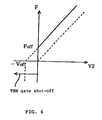
- Fig. 6 is a graph describing the photo-feedback operation of the present invention.
- FIG. 3 A first embodiment of the present invention with a rotary electric motor type non-tapered coaxial winding arrangement is shown in Fig. 3.
- a power supply side core A and a receiving side core B are formed of a magnetic material, for example, ferrite or amorphous alloy, with a required number of slots and teeth adapted for high frequency use (square wave 10 kHz or more).
- a teeth top surface of the power supply side core A and a teeth top surface of the receiving side core B are provided with respective teeth facing each other along circumferences of different diameters, the teeth having a power supply side winding Wa and a receiving side winding Wb respectively wound around teeth as shown in figure 3.
- figure 3 shows half turn windings for the sake of simplicity, actually it is wound a predetermined number of times and then shifts to the next tooth.
- windings Wa, Wb are made of plate-formed or square-formed native copper in order to increase the magnet motive force within its saturation magnetic flux density, to reduce skin effect due to high frequency, ordinary ohmic loss and stray current between windings.
- the power transmitting operation of the present invention is exactly the same as that of a separately excited DC machine in which revolution is restrained.
- core A or core B can serve as a power supply side (supply side of high frequency current), as a matter of convenience, it will be assumed here that core A is a power supply side and the invention will be described for the case wherein the receiving side core B is inserted into core A from outside.
- Core A and core B are provided oppositely, interposing a narrow gap which allows their easy coupling-uncoupling and a non-magnetic protection film (not shown) which protects the cores and functions as the electrical insulation of the winding.
- the original structure of the present embodiment is a rotary electric motor type, in which the above preferable opposite position is achieved by flowing an appropriate current to the receiving side (secondary side) winding when they are coupled (according to circumstances, flow DC, or short-circuits through resistance), and rotating core B in this state to a stable position (that is, the position in which respective teeth are located oppositely).
- core B is rotatably disposed, for example, by positioning core B in the center of core A by suspending the axial center of core B with a string, enabling very easy positioning of cores A and B.
- a center hole C of core B shown in Fig. 3 is used for controlling the later described power transmitting equipment, and serves as a passage for transmitting feedback information to the power supply side by means of optical pulse signals for performing sequence control or closed loop control, the information being generated according to the load condition of the secondary side. A control method using this hole will be described later.
- a further preferable embodiment of the present invention, shown in Fig. 4 is structured such that tapered core coupling surfaces are provided so that the diameters of the circles on which the teeth top surfaces are oppositely disposed may change along the center axis of the core coupling surfaces, enabling easy coupling-uncoupling of the cores due to irregularity of alignment and potential gradient thereof.
- configuration of the tapered portion is not limited to a linear form as shown in the figure, but can be made to a curved form.
- the embodiment shown in Fig. 4 is structured with a convex type receiving side and a concave type power supply side, it can be formed to a reverse configuration in the same way as the cores, for example, shown in Fig. 3 which cannot be tapered.
- a plate-formed (or square-formed) coil is wound along a slot, its magnetic flux density toward the center axis is naturally not uniform, therefore even when structured with a single-layer winding, it is possible to generate coupling and uncoupling forces if electric current is appropriately flowed to the secondary winding.
- Fig. 5 is a block diagram showing a drive control unit of the power transmission system of the present invention.
- A.C. voltage supplied from a commercial frequency power source AC through a main transformer Tr is inputted into thyristor bridge THB through resistance R1 provided for controlling an electric current, and receives a waveform chopping control signal due to later described phase control based on a voltage command Vref and secondary voltage feed back. After chopping, the waveform is smoothed and converted to D.C. to reduce voltage pulsation, by a capacitor C1, a reactor L1 and a further capacitor C2 in an inverter circuit INV.
- Inverter circuit INV is provided with a predriver which serves as a reference pulse signal generator for producing a high frequency voltage of 50 % duty and a switch composed of a MOSFET (or an IGBT)(neither are shown), and produces a pulse shape with an amplitude of approximately Vdc at a frequency of 10 KHz or more.
- Application of this high frequency voltage to the above power supply (primary side) winding produces a high frequency rectangular wave voltage in the receiving (secondary side) winding due to magnetic coupling in accordance with a winding ratio between the power supply winding and the receiving winding.
- This induced voltage is rectified by a diode bridge HDB which has a small amount of high frequency loss and ON-state voltage effect, and after passing through a LC filter for removing a high frequency vibration component caused by an existing carrier component or stray capacitance, it becomes load side (secondary side) voltage V2.
- This voltage is supplied to the load through a reactor L2 provided for controlling an electric current and via a reverse-flow block diode D.
- a single loop control that is, control by the result of comparing a feedback value of the load side (secondary side) voltage V2 with command Vref, will be considered.
- a voltage divided from the load side (secondary side) voltage V2 by a resistor R2 is added to a base offset voltage Voff to be used for shutting off the primary side thyristor THB and the sum is inputted into an operational amplifier OP1.
- the amplified output of the operational amplifier OP1 is inputted into a voltage/frequency converter VF, and converted into pulse frequency signals by conversion gain shown in Fig. 6.
- This pulse frequency signal is used as a drive signal of a light-emitting diode LED which constitutes a light signal generation circuit together with voltage/frequency converter VF, and the pulse frequency signals are converted into light pulses by means of this LED.
- the light pulses emitted from the light-emitting diode LED are propagated to the power supply side (primary side) through the hole C for light feedback use shown in Fig. 3 and Fig. 4.
- a light receiving photo-transistor PTr is disposed in the power supply side core A at the point where light pulses generated by above LED are propagated, and said photo-transistor PTr receives light pulses (infrared rays) emitted from the light-emitting diode LED for conversion into the pulse voltage of the fixed level.
- This pulse voltage is inputted into a frequency/voltage converter FV which constitutes a voltage signal generation circuit together with the photo-transistor PTr, and then converted into a voltage signal which by the action of the gain shown in Fig. 6 is the sum of a voltage corresponding to the portion of V2 provided by R2 and a voltage corresponding to the above offset voltage Voff.
- thyristor bridge THB When the mutual cores are separated, it is necessary to stop supplying power by terminating the excitation of the power supply side (primary side) through shut-off of thyristor bridge THB in order to eliminate consumption of reactive power. Further, in some cases, the load side voltage V2 drops to zero volt for some reason (for example, load short-circuit), however in this case, thyristor bridge THB need not be shut off and instead excitation of the power supply side (primary side) is controlled so as to stay within the rating of the power element constructing the inverter circuit INV.
- a control method is applied that compares the values of above FV output and Voff by means of comparator CMP which together with the thyristor bridge THB constitutes a shut-off circuit, the gate signal for THB being shut off when CMP judges that (V2 + Voff) ⁇ Voff.
- the voltage output by FV, an offset cancel voltage of reversed polarity, and a command voltage (Vref) are inputted into operational amplifier OP2, and amplified differential signals are transmitted through a limiter to become phase signals of a gate control circuit which are gained by timer measurement synchronized to a commercial frequency zero point obtained by ZDT (zero point detector). According to the above process, feedback is completed with reference to the load side voltage V2.
- the shut-off circuit for breaking power supply is composed of a comparator and a thyristor bridge
- semiconductor elements such as a GTO, a power transistor, a power FET which can be used in place of the thyristor bridge, and the shut-off circuit may be constructed by using any of these substitutes.
- control and protection features it is desirable to feed back and reflect much more secondary information to the control function, for example, such information as a battery temperature, charging current (when a battery is charged at the secondary side), and power supply effective value.
- the non-contact type power transmission system of the present invention has a core and windings structured on the concept of a rotary electric motor, not of a transformer, so that combination of the primary and secondary flux are strengthened in the coupled condition, and hence transmission power and transmission efficiency per unit volume of the power supply core are increased. Further, when the respective core coupling surfaces are tapered and appropriate electric currents are caused to flow in the primary and secondary windings, repulsive and sucking forces are generated therebetween, thereby making coupling/uncoupling of the cores easy to carry out.
- the light signal from the secondary side can make the secondary voltage correspond with the command voltage, it is possible to supply power in an atmosphere wherein power supply by connection/disconnection of an electrode is difficult such as an explosive atmosphere, in water or in vacuum where air-tightness is highly required, for example, at a chemical plant, an explosive gas generation site, a gasoline station, space, a submarine in water or a pump in water.
- the power transmission system of the present invention can be employed in the ordinary atmosphere wherein contact power supply by a connecting electrode or power supply by a trailing cable (lead wire) to a moving body is difficult due to such reasons as damage, wear, fatigue (for example, power supply to a tool portion of a machining center or to each axis of a multiple axes robot).
- the power transmission system of the present invention can prevent consumption of reactive power.
- the present invention makes it possible to effect non-contact power transmission in various cases which have been deemed not suitable for such power transmission, and also makes it possible to prevent consumption of reactive power, thereby largely contributing to industry.
Landscapes
- Engineering & Computer Science (AREA)
- Power Engineering (AREA)
- Inverter Devices (AREA)
- Dc-Dc Converters (AREA)
- Linear Motors (AREA)
- Current-Collector Devices For Electrically Propelled Vehicles (AREA)
- Ac-Ac Conversion (AREA)
Description
- The present invention relates to a non-contact power transmission system. Such systems are used to supply power to an autonomous mobile vehicle which is used in an environment wherein power supply by connecting an electrode is difficult, or to an autonomous mobile vehicle used in an ordinary environment wherein contact power supply by connecting an electrode or power supply by a trailing cable (lead wire) to a relatively moving body is difficult due to such reasons as damage, wear, or fatigue, for example, to an electric driverless transportation vehicle or the like which transports goods in a plant.
- A non-contact power transmission system of a first conventional type, the split core type using magnetic coupling, is known which type is usually structured to a model with the shell type transformer shown in Fig. 1 or to a model with a core type transformer shown in Fig. 2.
- These were provided, for example, as shown in Japanese Patent Laid-Open 58-74021 Gazette (=DE-A-31 311 05), for non-contact power transmission by coupling power supply and receiving portions with a small gap therebetween, a power supply portion comprising a power supply side winding Wa, a power supply side core A, a power supply side coupler D, and a receiving portion comprising a receiving side winding Wb, a receiving side core B and a receiving side coupler E.
- Though there are further power transmission systems, which supply electric power from a fixed portion to a rotary portion without contacting thereto as disclosed in Japanese Utility Model Publication 55-15297 Gazette or in Japanese Patent Laid-Open 61-281508 Gazette, all systems supply power to a rotary portion in rotating motion and are not applicable to an autonomous mobile vehicle like the non-contact power transmission system which is the object of the present invention.
- US-A-4 761 724 discloses a power transmission system of the non-contact type including two magnetic yokes carrying a primary and a secondary winding, respectively. Between these yokes a magnetically inhomogeneous disk is arranged to vary the extent of magnet coupling between the two yokes in accordance with the rotational position of the control disk. The voltage induced in the secondary winding by current flowing through the primary winding is controlled correspondingly. A light source forming part of the secondary side of the transformer is energized, when the output voltage of the secondary winding exceeds a predetermined level. The light thus generated is received by a light detector, the output signal of which is used in switching on an off a transistor forming part of an oscillator driving the primary winding of the transformer.
- FR-A-2 535 479 discloses an electric transformer associated to a universal joint of the ball and socket type. The bearing surfaces of this joint carry primary and secondary windings of a transformer in view of non-contact transmission of signals and electric energy.
- In order to increase transmission magnetic flux within the range of the core material saturation magnetic flux density in the above prior art power transmission system, it becomes necessary to increase the cross sectional area, thus structurally making it inevitable to make a large frame for the core.
- Further, since magnetic flux tends to leak in a butting type coupling as described above, it has been difficult to improve transmission efficiency.
- An object of the present invention is to provide non-contact power transmission system whose transmission power for the same volume and its efficiency are remarkably increased compared with the prior art systems by increasing the core utilization efficiency of the magnetically coupling portion and reducing leakage flux thereof.
- The invention will now be described in more detail by way of preferred embodiments thereof referring to the enclosed drawings. Therein:
- Fig. 1 is a view showing the structure of a conventional type example of a shell type transformer model.
- Fig. 2 is a view showing the structure of a conventional type example of a core type transformer model.
- Fig. 3 is a view showing the structure of a non-tapered type embodiment of a non contact power transmission system in accordance with the present invention.
- Fig. 4 is a view showing the structure of a tapered type embodiment of a non contact power transmission system in accordance with the present invention.
- Fig. 5 is a block diagram showing the structure of a control circuit to be used in a non contact power transmission system in accordance with the present invention.
- Fig. 6 is a graph describing the photo-feedback operation of the present invention.
- A first embodiment of the present invention with a rotary electric motor type non-tapered coaxial winding arrangement is shown in Fig. 3.
- A power supply side core A and a receiving side core B are formed of a magnetic material, for example, ferrite or amorphous alloy, with a required number of slots and teeth adapted for high frequency use (square wave 10 kHz or more).
- A teeth top surface of the power supply side core A and a teeth top surface of the receiving side core B are provided with respective teeth facing each other along circumferences of different diameters, the teeth having a power supply side winding Wa and a receiving side winding Wb respectively wound around teeth as shown in figure 3. Although figure 3 shows half turn windings for the sake of simplicity, actually it is wound a predetermined number of times and then shifts to the next tooth. Further, windings Wa, Wb are made of plate-formed or square-formed native copper in order to increase the magnet motive force within its saturation magnetic flux density, to reduce skin effect due to high frequency, ordinary ohmic loss and stray current between windings.
- The power transmitting operation of the present invention is exactly the same as that of a separately excited DC machine in which revolution is restrained. Though either one of core A or core B can serve as a power supply side (supply side of high frequency current), as a matter of convenience, it will be assumed here that core A is a power supply side and the invention will be described for the case wherein the receiving side core B is inserted into core A from outside.
- Core A and core B are provided oppositely, interposing a narrow gap which allows their easy coupling-uncoupling and a non-magnetic protection film (not shown) which protects the cores and functions as the electrical insulation of the winding. Though it is preferable to get the opposite position wherein respective teeth are positioned face to face with the maximum magnetic interlinkage, the original structure of the present embodiment is a rotary electric motor type, in which the above preferable opposite position is achieved by flowing an appropriate current to the receiving side (secondary side) winding when they are coupled (according to circumstances, flow DC, or short-circuits through resistance), and rotating core B in this state to a stable position (that is, the position in which respective teeth are located oppositely).
- In other words, this preferable positioning will be satisfied if core B is rotatably disposed, for example, by positioning core B in the center of core A by suspending the axial center of core B with a string, enabling very easy positioning of cores A and B.
- A center hole C of core B shown in Fig. 3 is used for controlling the later described power transmitting equipment, and serves as a passage for transmitting feedback information to the power supply side by means of optical pulse signals for performing sequence control or closed loop control, the information being generated according to the load condition of the secondary side. A control method using this hole will be described later.
- A further preferable embodiment of the present invention, shown in Fig. 4 is structured such that tapered core coupling surfaces are provided so that the diameters of the circles on which the teeth top surfaces are oppositely disposed may change along the center axis of the core coupling surfaces, enabling easy coupling-uncoupling of the cores due to irregularity of alignment and potential gradient thereof. Further, configuration of the tapered portion is not limited to a linear form as shown in the figure, but can be made to a curved form.
- Though the embodiment shown in Fig. 4 is structured with a convex type receiving side and a concave type power supply side, it can be formed to a reverse configuration in the same way as the cores, for example, shown in Fig. 3 which cannot be tapered. Though a plate-formed (or square-formed) coil is wound along a slot, its magnetic flux density toward the center axis is naturally not uniform, therefore even when structured with a single-layer winding, it is possible to generate coupling and uncoupling forces if electric current is appropriately flowed to the secondary winding.
- Though the above description particularly exemplifies the equipment with a single-layer structure, of course it is possible to apply a high frequency three phase structure to further increase transmission efficiency per unit volume and make an electric current flow bi-directional to improve commutation ripple.
- Fig. 5 is a block diagram showing a drive control unit of the power transmission system of the present invention.
- A.C. voltage supplied from a commercial frequency power source AC through a main transformer Tr is inputted into thyristor bridge THB through resistance R1 provided for controlling an electric current, and receives a waveform chopping control signal due to later described phase control based on a voltage command Vref and secondary voltage feed back. After chopping, the waveform is smoothed and converted to D.C. to reduce voltage pulsation, by a capacitor C1, a reactor L1 and a further capacitor C2 in an inverter circuit INV.
- In this way, the amplitude of input voltage Vdc of the inverter circuit INV is controlled so that the secondary voltage V2 will correspond with the voltage command Vref.
- Inverter circuit INV is provided with a predriver which serves as a reference pulse signal generator for producing a high frequency voltage of 50 % duty and a switch composed of a MOSFET (or an IGBT)(neither are shown), and produces a pulse shape with an amplitude of approximately Vdc at a frequency of 10 KHz or more. Application of this high frequency voltage to the above power supply (primary side) winding produces a high frequency rectangular wave voltage in the receiving (secondary side) winding due to magnetic coupling in accordance with a winding ratio between the power supply winding and the receiving winding. This induced voltage is rectified by a diode bridge HDB which has a small amount of high frequency loss and ON-state voltage effect, and after passing through a LC filter for removing a high frequency vibration component caused by an existing carrier component or stray capacitance, it becomes load side (secondary side) voltage V2. This voltage is supplied to the load through a reactor L2 provided for controlling an electric current and via a reverse-flow block diode D.
- Here, as an example of the most simple system control, a single loop control, that is, control by the result of comparing a feedback value of the load side (secondary side) voltage V2 with command Vref, will be considered. To be concrete, a voltage divided from the load side (secondary side) voltage V2 by a resistor R2 is added to a base offset voltage Voff to be used for shutting off the primary side thyristor THB and the sum is inputted into an operational amplifier OP1.
- The amplified output of the operational amplifier OP1 is inputted into a voltage/frequency converter VF, and converted into pulse frequency signals by conversion gain shown in Fig. 6. This pulse frequency signal is used as a drive signal of a light-emitting diode LED which constitutes a light signal generation circuit together with voltage/frequency converter VF, and the pulse frequency signals are converted into light pulses by means of this LED.
- The light pulses emitted from the light-emitting diode LED are propagated to the power supply side (primary side) through the hole C for light feedback use shown in Fig. 3 and Fig. 4. A light receiving photo-transistor PTr is disposed in the power supply side core A at the point where light pulses generated by above LED are propagated, and said photo-transistor PTr receives light pulses (infrared rays) emitted from the light-emitting diode LED for conversion into the pulse voltage of the fixed level. This pulse voltage is inputted into a frequency/voltage converter FV which constitutes a voltage signal generation circuit together with the photo-transistor PTr, and then converted into a voltage signal which by the action of the gain shown in Fig. 6 is the sum of a voltage corresponding to the portion of V2 provided by R2 and a voltage corresponding to the above offset voltage Voff.
- Now the purpose of the above offset, voltage will be described in move detail.
- When the mutual cores are separated, it is necessary to stop supplying power by terminating the excitation of the power supply side (primary side) through shut-off of thyristor bridge THB in order to eliminate consumption of reactive power. Further, in some cases, the load side voltage V2 drops to zero volt for some reason (for example, load short-circuit), however in this case, thyristor bridge THB need not be shut off and instead excitation of the power supply side (primary side) is controlled so as to stay within the rating of the power element constructing the inverter circuit INV.
- Thus, it is necessary to change the method for shutting off the line according to circumstances. If feed back of the load side voltage including frequency/voltage conversion is performed without adding an offset voltage, the same voltage (in Fig. 6, zero volts) is outputted in either case as may be seen from the gain shown in broken line in Fig. 6, thus failing to distinguish the two different situations.
- According to the present embodiment, it is possible to change the power supplying state by distinguishing the two situations by adding an offset voltage to the feed back voltage V2.
- When the cores A, B are separated, of course light pulses generated by the light-emitting diode LED are not received by the photo-transistor PTr, and the comparator CMP outputs -Voff by the gain shown in Fig. 6.
- On the other hand, when the two cores are coupled and load side voltage V2 becomes zero due to load short-circuit or the like, then the output voltage of the comparator CMP becomes zero.
- Thus the completion of core coupling is distinguished by the existence of offset Voff, thus enabling changing of the power supply state.
- To be concrete, a control method is applied that compares the values of above FV output and Voff by means of comparator CMP which together with the thyristor bridge THB constitutes a shut-off circuit, the gate signal for THB being shut off when CMP judges that (V2 + Voff) < Voff.
- The voltage output by FV, an offset cancel voltage of reversed polarity, and a command voltage (Vref) are inputted into operational amplifier OP2, and amplified differential signals are transmitted through a limiter to become phase signals of a gate control circuit which are gained by timer measurement synchronized to a commercial frequency zero point obtained by ZDT (zero point detector). According to the above process, feedback is completed with reference to the load side voltage V2.
- Now, in the above embodiment, though the shut-off circuit for breaking power supply is composed of a comparator and a thyristor bridge, there are semiconductor elements such as a GTO, a power transistor, a power FET which can be used in place of the thyristor bridge, and the shut-off circuit may be constructed by using any of these substitutes.
- As for control and protection features, it is desirable to feed back and reflect much more secondary information to the control function, for example, such information as a battery temperature, charging current (when a battery is charged at the secondary side), and power supply effective value.
- Though increased feedback information is required for performing these delicate controls, it is possible to cope with these requirements by means of techniques such as time-division or multichannel light feedback operation.
- Further, it is possible to employ PWM control for control of the power supply side corresponding to load side voltage V2 when consideration is given to use of a center tapped winding or the like to meet asymmetrical core magnetization.
- As described above, the non-contact type power transmission system of the present invention has a core and windings structured on the concept of a rotary electric motor, not of a transformer, so that combination of the primary and secondary flux are strengthened in the coupled condition, and hence transmission power and transmission efficiency per unit volume of the power supply core are increased. Further, when the respective core coupling surfaces are tapered and appropriate electric currents are caused to flow in the primary and secondary windings, repulsive and sucking forces are generated therebetween, thereby making coupling/uncoupling of the cores easy to carry out. Still further, since the light signal from the secondary side (power receiving side) can make the secondary voltage correspond with the command voltage, it is possible to supply power in an atmosphere wherein power supply by connection/disconnection of an electrode is difficult such as an explosive atmosphere, in water or in vacuum where air-tightness is highly required, for example, at a chemical plant, an explosive gas generation site, a gasoline station, space, a submarine in water or a pump in water.
- Furthermore, the power transmission system of the present invention can be employed in the ordinary atmosphere wherein contact power supply by a connecting electrode or power supply by a trailing cable (lead wire) to a moving body is difficult due to such reasons as damage, wear, fatigue (for example, power supply to a tool portion of a machining center or to each axis of a multiple axes robot).
- Moreover, when cooperating cores are separated and optical signals are not propagated to the primary side ( supply side), the thyristor bridge for generating the supply voltage is shut off, accordingly the power transmission system of the present invention can prevent consumption of reactive power.
- As described above, the present invention makes it possible to effect non-contact power transmission in various cases which have been deemed not suitable for such power transmission, and also makes it possible to prevent consumption of reactive power, thereby largely contributing to industry.
Claims (6)
- A non contact power transmission system for transmitting electric energy from a power source (AC) to a load, comprisingcharacterized in thata) a transformer includingaa) a primary core (A),ab) a primary winding (Wa) arranged on the primary core (A),ac) a secondary core (B),ad) a secondary winding (Wb) arranged on the secondary core (B),ae) means for coupling/uncoupling the primary and secondary windings (Wa, Wb),b) voltage sensing means (R2) connected to the output of the secondary winding (Wb),c) an optical signal transmitting line includingca) a controllabe light source (LED) forming part of the secondary side of the transformer, which is driven in accordance with an actual voltage signal output from the voltage sensing means (R2),cb) a light detector (PTr) forming part of the primary side of the transformer andcc) a passageway (C) extending between the light source (LED) and the light detector (PTr) andd) a current control circuit (THB) forming part of the primary side of the transformer, a control terminal of which is activated in accordance with an output signal of the light detector (PTr)e) the primary core (A) and the secondary core (B) are nested coaxial members of rotational symmetry,f) opposing surfaces of the primary core (A) and the secondary core (B) are each formed with a plurality of teeth, the two sets of teeth being equally spaced in circumferential direction,g) the teeth of the primary core (A) and the secondary core (B) each carry a fraction of the primary winding (Wa) and the secondary winding (Wb), respectively andh) the means for coupling/uncoupling the primary and secondary windings (Wa, Wb) consists of core mounting means allowing for relative rotational and/or axial movement of the primary core (A) and the secondary core (B).
- A power transmission system in accordance with claim 1, characterized in that the opposing surfaces of the primary core (A) and the secondary core (B), which are formed with opposing surfaces, are of generally frustoconical geometry.
- A power transmission system in accordance with claim 1 or 2, characterized in that the passageway (C) comprises two portions extending along the axis of the primary core (A) and the secondary core (B), respectively.
- A power transmission system as any of claims 1 to 3, characterized in that a voltage to frequency converter (VF) is connected between the output of the voltage sensing means (R2) and a control terminal of the light source (LED) and in that a frequency to voltage converter (FV) is connected between the output of the light detector (PTr) and the control terminal of the current control circuit (THB).
- A power transmission system in accordance with claim 4, characterized in that an output terminal of the voltage sensing means (R2) is connected to one input of an adding and amplification circuit (OP1), a second input of which receives an offset voltage signal (Voff), the output of the adding and amplification circuit (OP1) being connected to the voltage to frequency converter (VF), in that the output signal of the light detector (PTr) is supplied to the frequency to voltage converter (FV) whose output is connected to a first input of a comparator (CMP), a second input of which receives a voltage signal being of same amplitude as the offset voltage signal but of opposite polarity and in that the output signal of the comparator (CMP) is fed to one input of an AND gate, the second input of which receives control signals from the gate control circuit to switch off the current control circuit (THB) when the cores are separated.
- A power transmission system in accordance with claim 4, characterized in that the output signal of the light detector (PTr) is supplied to the frequency to voltage converter (FV) whose output is connected to one input of an adding and amplification circuit (OP2), the second input of which receives a desired voltage signal (Vref) and further a voltage signal, which has same amplitude but opposite polarity as the offset voltage signal (Voff), and in that the signal output from this adding and amplification circuit (OP2) is supplied to a control terminal of a gate control circuit providing control signals to the current control circuit (THB) such that the output of the voltage sensing means corresponds to the desired voltage (Vref).
Applications Claiming Priority (4)
| Application Number | Priority Date | Filing Date | Title |
|---|---|---|---|
| JP146936/91 | 1991-05-21 | ||
| JP14693691 | 1991-05-21 | ||
| JP03146936A JP3116418B2 (en) | 1991-05-21 | 1991-05-21 | Wireless power supply |
| PCT/JP1992/000583 WO1992021131A1 (en) | 1991-05-21 | 1992-05-08 | Apparatus for feeding power in non-contact way |
Publications (3)
| Publication Number | Publication Date |
|---|---|
| EP0540750A1 EP0540750A1 (en) | 1993-05-12 |
| EP0540750A4 EP0540750A4 (en) | 1993-10-20 |
| EP0540750B1 true EP0540750B1 (en) | 1999-07-14 |
Family
ID=15418923
Family Applications (1)
| Application Number | Title | Priority Date | Filing Date |
|---|---|---|---|
| EP92909988A Expired - Lifetime EP0540750B1 (en) | 1991-05-21 | 1992-05-08 | Apparatus for feeding power in non-contact way |
Country Status (5)
| Country | Link |
|---|---|
| US (1) | US5327073A (en) |
| EP (1) | EP0540750B1 (en) |
| JP (1) | JP3116418B2 (en) |
| DE (1) | DE69229589T2 (en) |
| WO (1) | WO1992021131A1 (en) |
Families Citing this family (17)
| Publication number | Priority date | Publication date | Assignee | Title |
|---|---|---|---|---|
| GB9310545D0 (en) * | 1993-05-21 | 1993-07-07 | Era Patents Ltd | Power coupling |
| KR100290160B1 (en) * | 1993-06-02 | 2001-05-15 | 기구치 고 | Hydraulic generating device and working machine equipped with this device |
| JP3469652B2 (en) * | 1994-09-26 | 2003-11-25 | 富士機械製造株式会社 | Electronic component mounting device |
| US5907231A (en) * | 1996-06-27 | 1999-05-25 | Sumitomo Electriic Industries, Ltd. | Magnetic coupling device for charging an electric vehicle |
| ZA981105B (en) * | 1997-02-20 | 1998-08-20 | Charles Bowker | Transfer of electrical energy |
| JP3363341B2 (en) * | 1997-03-26 | 2003-01-08 | 松下電工株式会社 | Non-contact power transmission device |
| US6268785B1 (en) * | 1998-12-22 | 2001-07-31 | Raytheon Company | Apparatus and method for transferring energy across a connectorless interface |
| US6759759B2 (en) * | 2000-08-29 | 2004-07-06 | Tamagawa Seiki Kabushiki Kaisha | Rotary contactless connector and non-rotary contactless connector |
| DE10319532B4 (en) * | 2003-04-30 | 2017-12-21 | BSH Hausgeräte GmbH | Device for the inductive transmission of energy |
| EP1482627A3 (en) * | 2003-05-28 | 2005-06-15 | Chin Shiou Chang | Isolated electric power generator by utilizing leaking magnetic flux |
| JP2008099425A (en) * | 2006-10-11 | 2008-04-24 | Dainippon Printing Co Ltd | Power supply |
| US7948340B2 (en) | 2007-08-29 | 2011-05-24 | Siemens Industry, Inc. | Three-phase multi-winding device |
| TW201101347A (en) * | 2009-01-12 | 2011-01-01 | Robert Ray Holcomb | Solid state rotary field electric power cogeneration unit |
| JP5210423B2 (en) * | 2011-09-06 | 2013-06-12 | ニッタ株式会社 | Electromagnetic coupling device |
| JP5852873B2 (en) * | 2011-12-16 | 2016-02-03 | Udトラックス株式会社 | Contactless power supply system |
| DE102012219254B4 (en) * | 2012-10-22 | 2015-01-29 | Sauer Ultrasonic Gmbh | Supply circuit, supply system, tool actuator, tool |
| DE102019123967A1 (en) * | 2019-09-06 | 2021-03-11 | Volkswagen Aktiengesellschaft | Battery system for a motor vehicle and motor vehicle with a replaceable battery |
Family Cites Families (8)
| Publication number | Priority date | Publication date | Assignee | Title |
|---|---|---|---|---|
| DE2029468A1 (en) * | 1970-06-11 | 1971-12-16 | Schering Ag | Device for contactless electn see energy transfer |
| DE2752783C2 (en) * | 1977-11-25 | 1979-08-30 | Siemens Ag, 1000 Berlin Und 8000 Muenchen | Device for acquiring and processing electrical signals |
| US4612503A (en) * | 1980-10-21 | 1986-09-16 | Kabushiki Kaisha S G | Rotation speed detection device having a rotation angle detector of inductive type |
| FR2535479A1 (en) * | 1982-10-29 | 1984-05-04 | Matra | Orientation device without solid friction, and application to a space vehicle. |
| JPS61271806A (en) * | 1985-05-27 | 1986-12-02 | Nippon Denzai Kogyo Kenkyusho:Kk | Power transmission control apparatus |
| JPS62290113A (en) * | 1986-06-09 | 1987-12-17 | Honda Motor Co Ltd | Apparatus for supplying power and the like |
| US4761724A (en) * | 1987-06-29 | 1988-08-02 | The United States As Represented By The United States Department Of Energy | Transformer coupling for transmitting direct current through a barrier |
| JPH0241408U (en) * | 1988-09-09 | 1990-03-22 |
-
1991
- 1991-05-21 JP JP03146936A patent/JP3116418B2/en not_active Expired - Fee Related
-
1992
- 1992-05-08 US US07/961,705 patent/US5327073A/en not_active Expired - Fee Related
- 1992-05-08 DE DE69229589T patent/DE69229589T2/en not_active Expired - Fee Related
- 1992-05-08 EP EP92909988A patent/EP0540750B1/en not_active Expired - Lifetime
- 1992-05-08 WO PCT/JP1992/000583 patent/WO1992021131A1/en not_active Ceased
Also Published As
| Publication number | Publication date |
|---|---|
| JPH04345008A (en) | 1992-12-01 |
| EP0540750A1 (en) | 1993-05-12 |
| WO1992021131A1 (en) | 1992-11-26 |
| EP0540750A4 (en) | 1993-10-20 |
| JP3116418B2 (en) | 2000-12-11 |
| DE69229589T2 (en) | 2000-02-17 |
| US5327073A (en) | 1994-07-05 |
| DE69229589D1 (en) | 1999-08-19 |
Similar Documents
| Publication | Publication Date | Title |
|---|---|---|
| US5327073A (en) | Load-dispatching apparatus having improved power supply cut-off | |
| US4654573A (en) | Power transfer device | |
| US5818188A (en) | Noncontacting electric power transfer apparatus, noncontacting signal transfer apparatus, split-type mechanical apparatus employing these transfer apparatus, and a control method for controlling same | |
| Kawamura et al. | Wireless transmission of power and information through one high-frequency resonant AC link inverter for robot manipulator applications | |
| Bieler et al. | Contactless power and information transmission | |
| Mecke et al. | High frequency resonant inverter for contactless energy transmission over large air gap | |
| KR0180047B1 (en) | Induction power distribution system | |
| Zhao et al. | A push–pull parallel resonant converter-based bidirectional IPT system | |
| CN101567570B (en) | Non-contact induction type charging system | |
| JPWO1993026020A1 (en) | Contactless power transmission device, contactless signal transmission device, and separate type mechanical device using these and control method thereof | |
| US9774218B2 (en) | Non-contact power feeding apparatus | |
| US9906067B1 (en) | Apparatus, system and method to wirelessly charge/discharge a battery | |
| Cai et al. | Magnetic coupled wireless motor driving systems–An overview | |
| JP3097319B2 (en) | Non-contact power supply control method for electric motor, separated control electric motor by the method, and mechanical device using the separated control electric motor | |
| Eekshita et al. | Wireless power transmission system | |
| US6362985B1 (en) | Power transmission apparatus and method for power transmission | |
| JPH07322535A (en) | Non-contact power supply device for linear motion mechanism | |
| JPH0666201U (en) | Non-contact power supply device for moving body on constant track | |
| JP3843523B2 (en) | Non-contact power feeding device | |
| CN213846576U (en) | A compound excitation controller for permanent magnet generator | |
| CN223809614U (en) | An ultrasonic wireless power transmission device | |
| Wang et al. | Compensation circuit and buck converter based wireless power transmission | |
| Ishida et al. | PT Symmetric Wireless Power Transfer System for Direct Drive of DC Motors | |
| Wang et al. | Design of an AUV Underwater Magnetic Resonant Wireless Power Transfer System | |
| US20230396093A1 (en) | Motor, charging apparatus, powertrain, and vehicle |
Legal Events
| Date | Code | Title | Description |
|---|---|---|---|
| PUAI | Public reference made under article 153(3) epc to a published international application that has entered the european phase |
Free format text: ORIGINAL CODE: 0009012 |
|
| AK | Designated contracting states |
Kind code of ref document: A1 Designated state(s): DE GB |
|
| 17P | Request for examination filed |
Effective date: 19930429 |
|
| A4 | Supplementary search report drawn up and despatched |
Effective date: 19930830 |
|
| AK | Designated contracting states |
Kind code of ref document: A4 Designated state(s): DE GB |
|
| 17Q | First examination report despatched |
Effective date: 19941213 |
|
| GRAG | Despatch of communication of intention to grant |
Free format text: ORIGINAL CODE: EPIDOS AGRA |
|
| GRAG | Despatch of communication of intention to grant |
Free format text: ORIGINAL CODE: EPIDOS AGRA |
|
| GRAH | Despatch of communication of intention to grant a patent |
Free format text: ORIGINAL CODE: EPIDOS IGRA |
|
| GRAH | Despatch of communication of intention to grant a patent |
Free format text: ORIGINAL CODE: EPIDOS IGRA |
|
| GRAA | (expected) grant |
Free format text: ORIGINAL CODE: 0009210 |
|
| AK | Designated contracting states |
Kind code of ref document: B1 Designated state(s): DE GB |
|
| REF | Corresponds to: |
Ref document number: 69229589 Country of ref document: DE Date of ref document: 19990819 |
|
| PGFP | Annual fee paid to national office [announced via postgrant information from national office to epo] |
Ref country code: GB Payment date: 20000503 Year of fee payment: 9 |
|
| PGFP | Annual fee paid to national office [announced via postgrant information from national office to epo] |
Ref country code: DE Payment date: 20000508 Year of fee payment: 9 |
|
| PLBE | No opposition filed within time limit |
Free format text: ORIGINAL CODE: 0009261 |
|
| 26N | No opposition filed | ||
| PG25 | Lapsed in a contracting state [announced via postgrant information from national office to epo] |
Ref country code: GB Free format text: LAPSE BECAUSE OF NON-PAYMENT OF DUE FEES Effective date: 20010508 |
|
| GBPC | Gb: european patent ceased through non-payment of renewal fee |
Effective date: 20010508 |
|
| PG25 | Lapsed in a contracting state [announced via postgrant information from national office to epo] |
Ref country code: DE Free format text: LAPSE BECAUSE OF NON-PAYMENT OF DUE FEES Effective date: 20020301 |