EP0540549B1 - Formation of porous materials - Google Patents
Formation of porous materials Download PDFInfo
- Publication number
- EP0540549B1 EP0540549B1 EP91912605A EP91912605A EP0540549B1 EP 0540549 B1 EP0540549 B1 EP 0540549B1 EP 91912605 A EP91912605 A EP 91912605A EP 91912605 A EP91912605 A EP 91912605A EP 0540549 B1 EP0540549 B1 EP 0540549B1
- Authority
- EP
- European Patent Office
- Prior art keywords
- surfactant
- liquid
- polymerisable
- carrier
- self
- Prior art date
- Legal status (The legal status is an assumption and is not a legal conclusion. Google has not performed a legal analysis and makes no representation as to the accuracy of the status listed.)
- Expired - Lifetime
Links
- 239000011148 porous material Substances 0.000 title claims abstract description 30
- 230000015572 biosynthetic process Effects 0.000 title claims description 6
- 239000007788 liquid Substances 0.000 claims abstract description 54
- 238000000034 method Methods 0.000 claims abstract description 23
- 229920000642 polymer Polymers 0.000 claims abstract description 11
- 239000004094 surface-active agent Substances 0.000 claims description 69
- XLYOFNOQVPJJNP-UHFFFAOYSA-N water Substances O XLYOFNOQVPJJNP-UHFFFAOYSA-N 0.000 claims description 47
- 239000004530 micro-emulsion Substances 0.000 claims description 25
- 239000000126 substance Substances 0.000 claims description 24
- 230000002209 hydrophobic effect Effects 0.000 claims description 23
- 239000000178 monomer Substances 0.000 claims description 13
- 239000000463 material Substances 0.000 claims description 12
- 150000003839 salts Chemical class 0.000 claims description 10
- 238000000576 coating method Methods 0.000 claims description 9
- 239000004215 Carbon black (E152) Substances 0.000 claims description 7
- 239000011248 coating agent Substances 0.000 claims description 7
- 229930195733 hydrocarbon Natural products 0.000 claims description 7
- 150000002430 hydrocarbons Chemical class 0.000 claims description 7
- PPBRXRYQALVLMV-UHFFFAOYSA-N Styrene Chemical compound C=CC1=CC=CC=C1 PPBRXRYQALVLMV-UHFFFAOYSA-N 0.000 claims description 6
- -1 alkyl methacrylate Chemical compound 0.000 claims description 6
- 239000000693 micelle Substances 0.000 claims description 6
- 150000005846 sugar alcohols Polymers 0.000 claims description 5
- 125000002348 vinylic group Chemical group 0.000 claims description 5
- 239000003999 initiator Substances 0.000 claims description 4
- 238000002156 mixing Methods 0.000 claims description 4
- 150000001336 alkenes Chemical class 0.000 claims description 3
- 239000004971 Cross linker Substances 0.000 claims description 2
- 239000000017 hydrogel Substances 0.000 claims description 2
- JRZJOMJEPLMPRA-UHFFFAOYSA-N olefin Natural products CCCCCCCC=C JRZJOMJEPLMPRA-UHFFFAOYSA-N 0.000 claims 2
- 230000000149 penetrating effect Effects 0.000 abstract 1
- 239000000203 mixture Substances 0.000 description 39
- 239000003921 oil Substances 0.000 description 35
- 239000012071 phase Substances 0.000 description 28
- 239000012528 membrane Substances 0.000 description 23
- 239000010410 layer Substances 0.000 description 9
- 238000010587 phase diagram Methods 0.000 description 9
- VYPSYNLAJGMNEJ-UHFFFAOYSA-N silicon dioxide Inorganic materials O=[Si]=O VYPSYNLAJGMNEJ-UHFFFAOYSA-N 0.000 description 9
- VVQNEPGJFQJSBK-UHFFFAOYSA-N Methyl methacrylate Chemical compound COC(=O)C(C)=C VVQNEPGJFQJSBK-UHFFFAOYSA-N 0.000 description 8
- 239000010453 quartz Substances 0.000 description 7
- TWRXJAOTZQYOKJ-UHFFFAOYSA-L Magnesium chloride Chemical compound [Mg+2].[Cl-].[Cl-] TWRXJAOTZQYOKJ-UHFFFAOYSA-L 0.000 description 6
- 239000010408 film Substances 0.000 description 6
- 238000001223 reverse osmosis Methods 0.000 description 6
- 239000000758 substrate Substances 0.000 description 6
- 238000000926 separation method Methods 0.000 description 5
- 239000002356 single layer Substances 0.000 description 5
- 229940126062 Compound A Drugs 0.000 description 4
- NLDMNSXOCDLTTB-UHFFFAOYSA-N Heterophylliin A Natural products O1C2COC(=O)C3=CC(O)=C(O)C(O)=C3C3=C(O)C(O)=C(O)C=C3C(=O)OC2C(OC(=O)C=2C=C(O)C(O)=C(O)C=2)C(O)C1OC(=O)C1=CC(O)=C(O)C(O)=C1 NLDMNSXOCDLTTB-UHFFFAOYSA-N 0.000 description 4
- FAPWRFPIFSIZLT-UHFFFAOYSA-M Sodium chloride Chemical compound [Na+].[Cl-] FAPWRFPIFSIZLT-UHFFFAOYSA-M 0.000 description 4
- ISAOCJYIOMOJEB-UHFFFAOYSA-N benzoin Chemical compound C=1C=CC=CC=1C(O)C(=O)C1=CC=CC=C1 ISAOCJYIOMOJEB-UHFFFAOYSA-N 0.000 description 4
- STVZJERGLQHEKB-UHFFFAOYSA-N ethylene glycol dimethacrylate Substances CC(=C)C(=O)OCCOC(=O)C(C)=C STVZJERGLQHEKB-UHFFFAOYSA-N 0.000 description 4
- 238000012360 testing method Methods 0.000 description 4
- DBCAQXHNJOFNGC-UHFFFAOYSA-N 4-bromo-1,1,1-trifluorobutane Chemical compound FC(F)(F)CCCBr DBCAQXHNJOFNGC-UHFFFAOYSA-N 0.000 description 3
- 239000004743 Polypropylene Substances 0.000 description 3
- 239000004411 aluminium Substances 0.000 description 3
- XAGFODPZIPBFFR-UHFFFAOYSA-N aluminium Chemical compound [Al] XAGFODPZIPBFFR-UHFFFAOYSA-N 0.000 description 3
- 229910052782 aluminium Inorganic materials 0.000 description 3
- 239000001913 cellulose Substances 0.000 description 3
- 229920002678 cellulose Polymers 0.000 description 3
- 239000000839 emulsion Substances 0.000 description 3
- 239000000706 filtrate Substances 0.000 description 3
- 229910001629 magnesium chloride Inorganic materials 0.000 description 3
- VLKZOEOYAKHREP-UHFFFAOYSA-N n-Hexane Chemical compound CCCCCC VLKZOEOYAKHREP-UHFFFAOYSA-N 0.000 description 3
- 229920001155 polypropylene Polymers 0.000 description 3
- 239000000047 product Substances 0.000 description 3
- 239000000243 solution Substances 0.000 description 3
- 238000004809 thin layer chromatography Methods 0.000 description 3
- BQZJOQXSCSZQPS-UHFFFAOYSA-N 2-methoxy-1,2-diphenylethanone Chemical compound C=1C=CC=CC=1C(OC)C(=O)C1=CC=CC=C1 BQZJOQXSCSZQPS-UHFFFAOYSA-N 0.000 description 2
- CSCPPACGZOOCGX-UHFFFAOYSA-N Acetone Chemical compound CC(C)=O CSCPPACGZOOCGX-UHFFFAOYSA-N 0.000 description 2
- IJGRMHOSHXDMSA-UHFFFAOYSA-N Atomic nitrogen Chemical compound N#N IJGRMHOSHXDMSA-UHFFFAOYSA-N 0.000 description 2
- HEDRZPFGACZZDS-UHFFFAOYSA-N Chloroform Chemical compound ClC(Cl)Cl HEDRZPFGACZZDS-UHFFFAOYSA-N 0.000 description 2
- LFQSCWFLJHTTHZ-UHFFFAOYSA-N Ethanol Chemical compound CCO LFQSCWFLJHTTHZ-UHFFFAOYSA-N 0.000 description 2
- 238000005481 NMR spectroscopy Methods 0.000 description 2
- 244000028419 Styrax benzoin Species 0.000 description 2
- 235000000126 Styrax benzoin Nutrition 0.000 description 2
- 235000008411 Sumatra benzointree Nutrition 0.000 description 2
- 150000001335 aliphatic alkanes Chemical class 0.000 description 2
- 229960002130 benzoin Drugs 0.000 description 2
- 239000003431 cross linking reagent Substances 0.000 description 2
- 238000010586 diagram Methods 0.000 description 2
- XRWMGCFJVKDVMD-UHFFFAOYSA-M didodecyl(dimethyl)azanium;bromide Chemical compound [Br-].CCCCCCCCCCCC[N+](C)(C)CCCCCCCCCCCC XRWMGCFJVKDVMD-UHFFFAOYSA-M 0.000 description 2
- SNRUBQQJIBEYMU-UHFFFAOYSA-N dodecane Chemical compound CCCCCCCCCCCC SNRUBQQJIBEYMU-UHFFFAOYSA-N 0.000 description 2
- 238000001704 evaporation Methods 0.000 description 2
- 230000008020 evaporation Effects 0.000 description 2
- 238000002474 experimental method Methods 0.000 description 2
- 235000019382 gum benzoic Nutrition 0.000 description 2
- DCAYPVUWAIABOU-UHFFFAOYSA-N hexadecane Chemical compound CCCCCCCCCCCCCCCC DCAYPVUWAIABOU-UHFFFAOYSA-N 0.000 description 2
- 239000012456 homogeneous solution Substances 0.000 description 2
- 239000012466 permeate Substances 0.000 description 2
- 238000006116 polymerization reaction Methods 0.000 description 2
- 239000011541 reaction mixture Substances 0.000 description 2
- 239000011780 sodium chloride Substances 0.000 description 2
- APSBXTVYXVQYAB-UHFFFAOYSA-M sodium docusate Chemical compound [Na+].CCCCC(CC)COC(=O)CC(S([O-])(=O)=O)C(=O)OCC(CC)CCCC APSBXTVYXVQYAB-UHFFFAOYSA-M 0.000 description 2
- 239000007787 solid Substances 0.000 description 2
- 230000009897 systematic effect Effects 0.000 description 2
- 238000009281 ultraviolet germicidal irradiation Methods 0.000 description 2
- 238000009736 wetting Methods 0.000 description 2
- IISHLYLZTYTIJJ-UHFFFAOYSA-N 1-hydroxyethyl 2-methylprop-2-enoate Chemical compound CC(O)OC(=O)C(C)=C IISHLYLZTYTIJJ-UHFFFAOYSA-N 0.000 description 1
- XFGANBYCJWQYBI-UHFFFAOYSA-N 11-bromoundecan-1-ol Chemical compound OCCCCCCCCCCCBr XFGANBYCJWQYBI-UHFFFAOYSA-N 0.000 description 1
- BFSVOASYOCHEOV-UHFFFAOYSA-N 2-diethylaminoethanol Chemical compound CCN(CC)CCO BFSVOASYOCHEOV-UHFFFAOYSA-N 0.000 description 1
- 229940013085 2-diethylaminoethanol Drugs 0.000 description 1
- JFXQHCGXCZQLLV-UHFFFAOYSA-N 2-methylpent-2-eneperoxoic acid Chemical compound C(C)C=C(C(=O)OO)C JFXQHCGXCZQLLV-UHFFFAOYSA-N 0.000 description 1
- RZVAJINKPMORJF-UHFFFAOYSA-N Acetaminophen Chemical compound CC(=O)NC1=CC=C(O)C=C1 RZVAJINKPMORJF-UHFFFAOYSA-N 0.000 description 1
- QTBSBXVTEAMEQO-UHFFFAOYSA-M Acetate Chemical compound CC([O-])=O QTBSBXVTEAMEQO-UHFFFAOYSA-M 0.000 description 1
- 239000004342 Benzoyl peroxide Substances 0.000 description 1
- OMPJBNCRMGITSC-UHFFFAOYSA-N Benzoylperoxide Chemical compound C=1C=CC=CC=1C(=O)OOC(=O)C1=CC=CC=C1 OMPJBNCRMGITSC-UHFFFAOYSA-N 0.000 description 1
- CPELXLSAUQHCOX-UHFFFAOYSA-M Bromide Chemical compound [Br-] CPELXLSAUQHCOX-UHFFFAOYSA-M 0.000 description 1
- 239000004677 Nylon Substances 0.000 description 1
- 229910000831 Steel Inorganic materials 0.000 description 1
- 239000000654 additive Substances 0.000 description 1
- 238000004220 aggregation Methods 0.000 description 1
- 150000001298 alcohols Chemical class 0.000 description 1
- 239000003945 anionic surfactant Substances 0.000 description 1
- 238000013459 approach Methods 0.000 description 1
- 239000008346 aqueous phase Substances 0.000 description 1
- QVGXLLKOCUKJST-UHFFFAOYSA-N atomic oxygen Chemical compound [O] QVGXLLKOCUKJST-UHFFFAOYSA-N 0.000 description 1
- 235000019400 benzoyl peroxide Nutrition 0.000 description 1
- 229910002056 binary alloy Inorganic materials 0.000 description 1
- 239000012876 carrier material Substances 0.000 description 1
- 239000003093 cationic surfactant Substances 0.000 description 1
- 239000000919 ceramic Substances 0.000 description 1
- 238000006243 chemical reaction Methods 0.000 description 1
- 238000004140 cleaning Methods 0.000 description 1
- 239000002131 composite material Substances 0.000 description 1
- 150000001875 compounds Chemical class 0.000 description 1
- 238000001816 cooling Methods 0.000 description 1
- 230000007423 decrease Effects 0.000 description 1
- 238000010790 dilution Methods 0.000 description 1
- 239000012895 dilution Substances 0.000 description 1
- 210000003027 ear inner Anatomy 0.000 description 1
- 230000000694 effects Effects 0.000 description 1
- 239000000499 gel Substances 0.000 description 1
- 238000010438 heat treatment Methods 0.000 description 1
- 230000005764 inhibitory process Effects 0.000 description 1
- 238000007689 inspection Methods 0.000 description 1
- 150000002500 ions Chemical class 0.000 description 1
- 238000002386 leaching Methods 0.000 description 1
- 238000013178 mathematical model Methods 0.000 description 1
- VHRYZQNGTZXDNX-UHFFFAOYSA-N methacryloyl chloride Chemical compound CC(=C)C(Cl)=O VHRYZQNGTZXDNX-UHFFFAOYSA-N 0.000 description 1
- 238000001471 micro-filtration Methods 0.000 description 1
- 238000012986 modification Methods 0.000 description 1
- 230000004048 modification Effects 0.000 description 1
- 238000001956 neutron scattering Methods 0.000 description 1
- 229910052757 nitrogen Inorganic materials 0.000 description 1
- 239000002736 nonionic surfactant Substances 0.000 description 1
- 229920001778 nylon Polymers 0.000 description 1
- 239000007764 o/w emulsion Substances 0.000 description 1
- 239000001301 oxygen Substances 0.000 description 1
- 229910052760 oxygen Inorganic materials 0.000 description 1
- 238000012856 packing Methods 0.000 description 1
- 230000000737 periodic effect Effects 0.000 description 1
- 238000000614 phase inversion technique Methods 0.000 description 1
- 229920000728 polyester Polymers 0.000 description 1
- 238000000746 purification Methods 0.000 description 1
- 239000005297 pyrex Substances 0.000 description 1
- 239000000376 reactant Substances 0.000 description 1
- 230000000717 retained effect Effects 0.000 description 1
- 238000002390 rotary evaporation Methods 0.000 description 1
- 239000000377 silicon dioxide Substances 0.000 description 1
- 229920002545 silicone oil Polymers 0.000 description 1
- 238000000235 small-angle X-ray scattering Methods 0.000 description 1
- 239000012265 solid product Substances 0.000 description 1
- 239000002904 solvent Substances 0.000 description 1
- 238000000638 solvent extraction Methods 0.000 description 1
- 238000001330 spinodal decomposition reaction Methods 0.000 description 1
- 229910001220 stainless steel Inorganic materials 0.000 description 1
- 239000010935 stainless steel Substances 0.000 description 1
- 239000010959 steel Substances 0.000 description 1
- 238000003786 synthesis reaction Methods 0.000 description 1
- 239000010409 thin film Substances 0.000 description 1
- 238000000108 ultra-filtration Methods 0.000 description 1
- 239000007762 w/o emulsion Substances 0.000 description 1
Images


Classifications
-
- B—PERFORMING OPERATIONS; TRANSPORTING
- B01—PHYSICAL OR CHEMICAL PROCESSES OR APPARATUS IN GENERAL
- B01D—SEPARATION
- B01D67/00—Processes specially adapted for manufacturing semi-permeable membranes for separation processes or apparatus
- B01D67/0002—Organic membrane manufacture
- B01D67/0006—Organic membrane manufacture by chemical reactions
-
- B—PERFORMING OPERATIONS; TRANSPORTING
- B01—PHYSICAL OR CHEMICAL PROCESSES OR APPARATUS IN GENERAL
- B01D—SEPARATION
- B01D69/00—Semi-permeable membranes for separation processes or apparatus characterised by their form, structure or properties; Manufacturing processes specially adapted therefor
- B01D69/10—Supported membranes; Membrane supports
-
- B—PERFORMING OPERATIONS; TRANSPORTING
- B01—PHYSICAL OR CHEMICAL PROCESSES OR APPARATUS IN GENERAL
- B01D—SEPARATION
- B01D69/00—Semi-permeable membranes for separation processes or apparatus characterised by their form, structure or properties; Manufacturing processes specially adapted therefor
- B01D69/12—Composite membranes; Ultra-thin membranes
- B01D69/125—In situ manufacturing by polymerisation, polycondensation, cross-linking or chemical reaction
-
- B—PERFORMING OPERATIONS; TRANSPORTING
- B01—PHYSICAL OR CHEMICAL PROCESSES OR APPARATUS IN GENERAL
- B01D—SEPARATION
- B01D2325/00—Details relating to properties of membranes
- B01D2325/02—Details relating to pores or porosity of the membranes
- B01D2325/022—Asymmetric membranes
Definitions
- This invention relates to the formation of polymeric coatings on a support or carrier.
- the invention is especially concerned with the formation of coatings of porous material from self-assembled microstructured liquids suitable for use in microfiltration, ultrafiltration and reverse osmosis.
- hydrophobic liquids such as oil and hydrophilic liquids such as water do not normally mix they can do in the presence of an amphiphilic substance such as surfactant.
- the hydrophobic component will hereinafter be termed an oil and the hydrophilic component will be termed water.
- an oil/water/surfactant mixture can form an emulsion.
- Such an emulsion may be a water-in-oil emulsion where usually water is the dispersed phase and oil is the continuous phase or an oil-in-water emulsion where oil is the dispersed phase and water is the continuous phase.
- a surfactant is characterised by a hydrophilic head group and a hydrophobic tail group.
- the tail group usually consists of a single paraffinic hydrocarbon type of chain but may be more complex.
- the present invention is particularly concerned with surfactants in which the tail group is a double chain which is usually sparingly soluble in both oil and water.
- amphiphilic nature of surfactant molecules leads to self-aggregation in solution as the surfactant molecules isolate hydrophobic regions from hydrophilic regions.
- the mixture surprisingly becomes clear and sometimes colourless which, on a scale of the wave length of light, indicates that the mixture is a homogeneous solution.
- the apparently homogeneous solution exhibits a fixed, quantifiable structure on the microscopic scale and this structure forms spontaneously.
- thermodynamically stable clear solutions are called microemulsions.
- the invention will, in the main, be described in relation to ternary systems which form microemulsions, it is to be understood that the invention is not limited thereto as other microstructured liquids will be useful.
- certain binary systems such as methyl methacrylate and hexadecane or polymerisable surfactant and water may be used to form porous material as may quaternary and other multi-component systems which can include salt, mixtures of oil, mixed surfactants as well as polymeric additives to an oil or water.
- Such mixtures are said to exhibit a self-assembled microstructure and often consist of bicontinuous phases separated by a surfactant monolayer or bilayer (they may, however, consist of disconnected spheres of water-in-oil or vice versa).
- a surfactant monolayer one phase (or sub-volume) is an oil phase and the other phase is an aqueous phase.
- both labyrinths are either both oily or both aqueous and the space between the surfactant bilayer may be swelled respectively by the inclusion of water or of an oil.
- the surface formed by the surfactant achieves a shape which complies with established thermodynamic laws and which represents a global or local minimum energy which fulfils both global and local packing constraints required for the surfactant molecules.
- the constraints on a particular surfactant depend on the nature of the oil or water. For example, a short chain alkane like hexane will penetrate more strongly into the hydrocarbon surfactant tails than will a long chain alkane such as dodecane and impose on the formed surfactant film more curvature than the latter.
- curvature is set by a balance of three forces. These are: the repulsive head-group forces, the hydrophobic attraction between the tails in water and a repulsive force acting between the hydrocarbon tails constrained by the interface.
- the homogeneous and optically transparent mixtures lie in single phase regions of the phase diagram of the multi-component system.
- These single phases may be of a crystalline nature (such as lamellar, hexagonal or cubic) which indicates an ordered compartmentisation of components in the mixture with a geometrically regular and repeated structure or a non-crystalline microemulsion in which compartmentisation is random and isotropic.
- the invention is particularly but not exclusively concerned with water-continuous structures containing well-defined pores such as microemulsions and the cubic phases. It also includes inverted micelle phases.
- cubic phase mixtures form viscous gels, which are optically isotropic.
- the mixture forms a partitioning into oil, water and surfactant regions which lie on a three-dimensional lattice of cubic symmetry (body-centred cubic, face-centred cubic or simple cubic). This can be established by small-angle X-ray or neutron scattering.
- Theoretical studies indicate that in bi-continuous cubic phases, the surfactant forms one of two possible structural classes.
- normal oil-swollen bilayers lie on a periodic cubic minimal surface.
- the oil-swollen bilayer forms a thin film on the surface and the surfactant head groups plus water form two interpenetrating tunnel networks separated by the bilayers. While symmetry is cubic, the topology of the underlying unit cell of the lattice can be very complex.
- the other class of structure (herein termed a class II structure) consists of reversed water-swollen bilayers with the oil forming the interpenetrating tunnels and with hydrophobic moiety (head groups and water) lying on a cubic minimal surface.
- the first class of structure is important, since the water networks consist of geometrically ordered interconnected pores of well-defined sizes such as diameters in the range 5-200 ⁇ .
- the second class of structure is of interest.
- Cubic phases are of interest because the tunnel sizes are very well defined due to the crystalline morphology and because the pore space can be enormous, in some cases greater than 90% by volume of the total volume, allowing for high flow rates.
- the microstructure within a cubic phase can vary with composition throughout the phase.
- the symmetry of the structure (that is the lattice symmetry) can change such as from face-centred cubic to body-centred cubic.
- the topology (that is, the number of pore tubes per unit cell) may vary.
- Microemulsions are non-viscous optically isotropic transparent mixtures which are thermodynamically stable. They are single phase mixtures which give rise to a single broad peaks in small-angle scattering due to a characteristic length scale typically 5-200 ⁇ .
- microstructures can occur within the general class of microemulsion structures. Typically, they may consist of micelles or reverse micelles (spheres formed by a monolayer of surfactant molecules which contain water or oil respectively) arranged randomly in the water or oil.
- the microstructures may also be interconnected monolayer films of surfactant, forming random (i.e. no crystalline lattice) surfaces of constant mean curvature, which can be visualised loosely as spheres placed randomly in space and joined to other closeby spheres by cylinders(herein referred to as class I microemulsions).
- the average number of cylinders connected to a single sphere is termed the coordination number.
- microemulsion may also form bilayers laying on disordered minimal surfaces (herein called class II microemulsions).
- Microstructures of inter-connected water pores can be inferred from the phase diagrams of the mixtures.
- a microemulsion region which forms a tear-drop shape emerging from the oil corner of the ternary phase diagram (typical of class I microemulsions curved towards water) is of particular importance to the invention.
- microemulsions consisting of monolayers of surfactant forming random surfaces of constant mean curvature, curved towards water, the microstructure varies continuously with composition. For example, a number of changes occur when a sample of fixed surfactant to oil ratio is diluted with water.
- the structure consists of a highly interconnected network of tubes the diameter of which is just large enough to contain the surfactant head-groups comfortably. As water is added, the diameter increases to accommodate the extra water, but the coordination number decreases in order to retain the preferred curvature of the surfactant monolayer.
- the coordination number attains its minimum (zero) and hence the structure consists of a random array of reverse micelles.
- the structure is water-continuous (which is essential for reverse osmosis membranes) only if the coordination number exceeds one.
- the pore dimensions and topology or connectivity can be changed by altering the surfactant and/or oil molecular geometry as well as by altering composition.
- the longer the chain length of the oil the smaller the resulting film curvature, so the larger the pore size.
- the surfactant surface is characterised by having ordered or randomly intersecting tubes or conduits throughout, with nodular or bead-like shaped entities as at the conduit intersections.
- the conduits between the intersections may be straight or in a series of straight sections.
- the conduits may also be blind.
- the structures in the liquid state are, of course, dynamic.
- topological parameters can be used to determine the characteristics of the surface of both crystalline (e.g. cubic) and microemulsion type sell-assembled microstructures.
- crystalline self-assembled microstructures many bicontinuous and related constant average curvature surfaces exist for any space group symmetry. These surfaces are distinguishable by their topology and are characterised by the genus per unit cell of the surface. Thus, symmetry alone is inadequate for structural assignation of such microstructures.
- an asymmetric or double-sided porous material which comprises at least one porous layer of a polymer on a porous support or carrier, said polymer being formed from a self-assembled microstructured liquid which liquid is formed by mixing components (a) to (c):
- a coating of a polymeric porous material on a porous support or carrier comprising the steps of:
- the support may be more porous than the coating or less active in a separation sense than the coating. Obviously, the support should not be dissolved by any component of the polymerisable liquid. Anchorage of the coating anchored to the support may occur by way of chemical adhesion, interpenetration or polymerisation, or any combination of such effects.
- a wide variety of materials can be used for the support or carrier material.
- ordinary cellulose filter paper is a cheap and versatile substrate for this purpose, but a wide range of thin porous substrates are available to which this procedure of the invention can be easily applied.
- more chemically resistant inorganic substrates such as porous pyrex sheets or ceramic paper, or organic substrates such as nylon/polyester mesh may be used.
- the porous material of the invention may comprise a layer of the polymer on only one side of the porous support or carrier, or there may be a layer on two sides. In the latter case the above described method may involve the use of two inert surfaces, with the support or carrier positioned between them.
- the method of the invention may be applied to any suitable liquid or mixture which can be solidified.
- the method may be applied to produce a membrane product from a self-assembled microstructured liquid, particularly a microemulsion, a bicontinuous crystalline phase, an inverted micelle microemulsion or a surfactant hydrogel.
- the self-assembled microstructured liquid used according to the invention may be prepared by a method comprising the steps of:-
- the hydrophobic substance may be selected from a wide variety of polymerisable materials, such as vinylic or olefinic monomers and mixtures thereof. For example, alkyl methacrylates, styrene and/or straight or branched olefins may be used.
- the polymerisable material may also contain one or more additional substances which act as crosslinkers, viscosifiers and initiators in the polymerisation process.
- the hydrophobic substance may contain a dissolved polymer for additional strength.
- the hydrophilic substance may consist of water, water containing dissolved salt(s), a monohydric or polyhydric alcohol, or any other hydrophilic polar liquid.
- surfactant A wide variety of materials may be used as the surfactant including anionic surfactants, cationic surfactants and non-ionic surfactants. Preferred substances for polar separation will have an effective surfactant parameter in excess of one.
- the surfactants contain two or more hydrophobic chains and containing one or more polymerisable groups.
- the effective surfactant parameter provides a means of predicting curvature and hence pore dimensions in the porous material.
- the surfactant parameter can be varied in a systematic way and can be predicted by choice of oil, mixtures of surfactant, variation of surfactant chain length, head group or by addition of salt.
- Admixing of single chain and double chain surfactants will reduce the surfactant parameter and result in larger pores.
- Admixing of long chain alcohols will increase the surfactant parameter and result in smaller pores provided that the surfactant parameter is greater than one.
- Addition of a strongly hydrated counter ion such as acetate will increase head group repulsion as compared with bromide to reduce the surfactant parameter and give larger pores provided that the surfactant parameter is greater than one.
- Asymmetric membranes or porous materials from self-assembled microstructures in accordance with the invention can be produced by the procedures illustrated in Figures 1 and Figure 1a.
- ordinary cellulose filter paper 100 is held against a smooth inert wall 101 (e.g. steel or quartz) and then wetted by the polymerisable liquid 102.
- the liquid 102 which is also present as a reservoir 103 in contact with the filter paper 100, produces a uniform equilibrium wetting film between the paper 100 and the wall 101.
- the paper 100 remains thoroughly wetted by the liquid 102.
- Most liquids will produce this film as a thermodynamic state of equilibrium. Even viscous liquids such as the cubic phase, given time, will attain the same state. It is advantageous to maintain vapour equilibrium to avoid changes in the composition of the mixture.
- the mixture can be polymerised to produce an asymmetric membrane.
- Thermal polymerisation is perhaps, the simplest procedure but UV irradiation through a silica or quartz wall (such as 101a) will produce the same result and, in general, more quickly (see Figure 1a).
- the membrane can be pulled off the wall relatively easily. Techniques, such as rapid cooling or heating of the wall facilitate this process as does pre-coating of the walls with a thin layer of silicone oil.
- the membrane once peeled away, generally has a similar degree of smoothness to the wall and may even retain the fine structure of the wall surface.
- the arrangement shown in Figure 1a is generally similar to that of Figure 1.
- the inert wall 101a is a quartz plate and the apparatus includes a thin clear polypropylene sheet 105 (to reduce evaporation) and a rigid, thin aluminium sheet 106 to enable the whole assembly to be clamped together.
- the wall 101 had a surface of stainless steel 316 machined with a sharply pointed tool to produce an undulating surface with a period of 200 micrometres.
- the resulting composite sheet had a high degree of polymerisation in the skin-layer and a more open structure in the cellulose support. This was illustrated by the observation that polymerisation of various liquids (e.g. methylmethacrylate) drawn into filter paper held away from the wall, allowed water to flow through relatively easily when under pressure of a few atmospheres.
- a suitable solvent e.g. ethanol
- a polymerisable microemulsion liquid mixture e.g. 26% methyl methacrylate as the polymerisable oil, 1% benzoyl peroxide as initiator, 3% ethylene glycol dimethacrylate as cross linking agent, 30% water and 40% Aerosol-OT surfactant
- Typical thermal polymerisation conditions are 55 °C for 20hr. The composition was investigated by testing its conductivity and was found to be bicontinuous before polymerisation.
- This product had a more waxy feel, especially on the porous support side and surfactant can obviously be leached out in water.
- This material has some of the characteristics of an ultrafilter.
- UV polymerization process used 4 % methylmethacrylate as polymerizable oil, 1% benzoin and 1% benzoin methyl ether as initiators, 9% ethylene glycol dimethacrylate as cross linking agent, 8% water and 40% didodecyl dimethyl ammonium bromide (DDAB) surfactant.
- DDAB didodecyl dimethyl ammonium bromide
- the thermal experiments were carried out in a sealed container charged with nitrogen to prevent oxygen inhibition to polymerisation of the methyl methacrylate.
- Double-sided membranes or porous materials may be produced by a modification of the apparatus of Figure 1a in which the sheets 105 and 106 are replaced by a second quartz plate. Using this arrangement, the liquid (102) can be made to wet both sides of the paper (100).
- Figure 2 is a phase diagram of a ternary oil/water/surfactant, mixture which forms a self-assembled microstructured clear liquid (shaded region) useful as a polymerizable liquid in accordance with the invention.
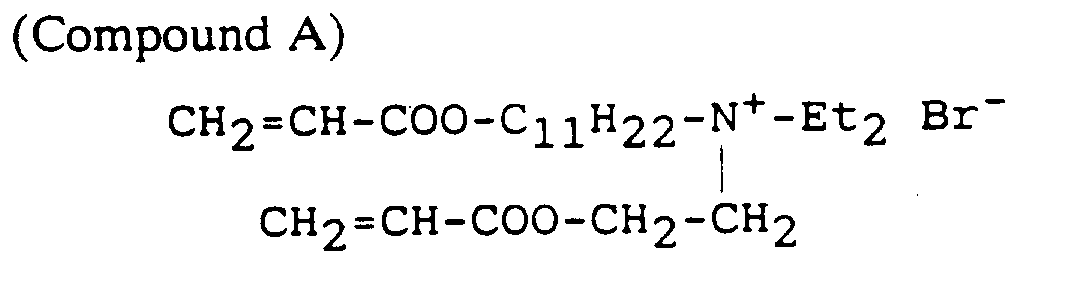
- the surfactant(s) is compound A
- "W” is pure water
- "O” is a mixture of polymerizable oils of composition: methylmethacrylate (32%) 1-hydroxy ethylmethacrylate (42%) and ethylene glycol di-methacrylate (26%).
- the phase diagram was determined at 25 °C. Information from the phase diagram was used to establish the composition used in the next part of the example.
- the clamped assembly was then held vertically in an Oliphant UV irradiation chamber and irradiated for about 30 minutes at room temperature.
- the sheet of aluminium was then removed and the polypropylene sheet peeled off.
- the membrane could then be gently lifted off the quartz substrate and post-cured in a scaled bag at room temperature for 24 hours.
- a piece of the membrane (a disc 39mm diameter, i.e. 12.5 cm 2 area) was tested for salt rejection in a reverse osmosis (RO) test cell, with the active side of the membrane facing the feed.
- RO reverse osmosis
- Permeate was collected from the cell and the conductivity of the permeate and the feed are compared to ascertain the level of salt rejection.
Landscapes
- Chemical & Material Sciences (AREA)
- Chemical Kinetics & Catalysis (AREA)
- Engineering & Computer Science (AREA)
- Manufacturing & Machinery (AREA)
- Colloid Chemistry (AREA)
- Separation Using Semi-Permeable Membranes (AREA)
Abstract
Description
- (a) a hydrophobic substance comprising at least one polymerisable monomer selected from vinylic and olefinic monomers;
- (b) a hydrophilic substance selected from water, water containing dissolved salt(s), a monohydric or polyhydric alcohol, and any other hydrophilic polar liquids; and
- (c) a surfactant having two or more hydrocarbon tails and containing one or more polymerisable groups.
- Figure 1
- is a schematic diagram of apparatus for forming a porous material according to one embodiment of the invention; and Figure 1a is a schematic diagram of a similar apparatus for forming a porous material by UV polymerization.
- Figure 2
- is a phase diagram of a ternary oil/water/surfactant mixture which forms a self-assembled microstructured clear liquid (shaded region) useful as a polymerisable liquid in accordance with the invention.

| Material | (by wt) | Actual |
| Compound A | 70% | 69.78% |
| Methyl methacrylate | 4.9% | 4.47% |
| Ethylene glycol dimethacrylate | 3% | 3.10% |
| 1-hydroxyethylmethacrylate | 4% | 4.59% |
| Water | 17% | 17.05 |
| Benzoin | ||
| 1% | 0.73% | |
| | 1% | 0.50% |
- DS5
- = 82% rejection of NaCl (0.5 g/Litre)
- Filtrate
- = 3871 x 10-15m3/sec/Pa/m2 (2304 Litres/day/1000 PSI/m2)
- DS3
- = 95% rejection of NaCl (0.5g/Litre)
- Filtrate
- = 2485 x 10-15m3/sec/Pa/m2 (1479 Litres/day/1000 PSI/m2)
- 1st run
- = 20% rejection of MgCl2 (0.5g/Litre)
- 2nd run
- = 26% rejection of MgCl2 (0.5g/Litre)
- Filtrate
- = 84.7m3/sec/Pa/m2 (50.5 Litre/day/1000 PSI/m2)
- 1st run
- = 6% rejection of MgCl2 (0.5g/Litre)
Claims (10)
- An asymmetric or double-sided porous material, characterised in that it comprises at least one porous layer of a polymer on a porous support or carrier, said polymer being formed from a self-assembled microstructured liquid which liquid is formed by mixing components (a) to (c):(a) a hydrophobic substance comprising at least one polymerisable monomer selected from vinylic and olefinic monomers;(b) a hydrophilic substance selected from water, water containing dissolved salt(s), a monohydric or polyhydric alcohol, and any other hydrophilic polar liquids; and(c) a surfactant having two or more hydrocarbon tails and containing one or more polymerisable groups.
- A material as claimed in Claim 1, characterised in that the self-assembled microstructured liquid is a microemulsion, a bicontinuous crystalline phase, an inverted micelle microemulsion or a surfactant hydrogel.
- A material as claimed in Claim 1 or Claim 2, characterised in that the polymerisable monomer is an alkyl methacrylate, styrene or a straight or branched olefin.
- A material as claimed in any one of Claims 1 to 3, characterised in that the hydrophobic substance (a) also contains at least one dissolved polymer.
- A method of forming a coating of a polymeric porous material on a porous support or carrier comprising the steps of:-said polymerisable liquid being formed from a self-assembled microstructured liquid formed by mixing components (a) to (c):(i) providing an inert surface,(ii) positioning the support or carrier against or adjacent to the surface,(iii) providing an excess of polymerisable liquid to completely wet the support or carrier and fill the space between this and the inert surface,(iv) allowing the polymerisable liquid to form a film through capillary action between the support or carrier and the inert surface and to penetrate the support or carrier,(v) polymerising the liquid;(a) a hydrophobic substance comprising at least one polymerisable monomer selected from vinylic and olefinic monomers;(b) a hydrophilic substance selected from water, water containing dissolved salt(s), a monohydric or polyhydric alcohol, and any other hydrophilic polar liquids; and(c) a surfactant having two or more hydrocarbon tails and containing one or more polymerisable groups.
- A method as claimed in Claim 5, including the steps of forming the polymerisable self-assembled microstructured liquid by:(i) selecting the hydrophobic substance and the surfactant so that the surfactant when swollen by the hydrophobic substance has an effective surfactant parameter (as hereinbefore described) greater than one.(ii) selecting ratios of the three substances (a), (b) and (c) that will give the self-assembled microstructure;(iii) causing or allowing the microstructure to form and allowing the surfactant molecules to self-aggregate so as to define a surfactant layer which separates the hydrophobic phase from the hydrophilic phase.
- A method as claimed in Claim 5 or Claim 6, characterised in that the polymerisable monomer is an alkyl methacrylate, styrene or a straight or branched olefin.
- A method as claimed in any one of Claims 5 to 7, characterised in that the hydrophobic substance (a) also contains at least one dissolved polymer.
- A method as claimed in any one of Claims 5 to 8, characterised in that the hydrophobic substance (a) contains one or more additional substances which act as crosslinkers, viscosifiers and initiators in the polymerisation.
- Use of a polymerisable liquid formed from a self-assembled microstructured liquid as defined in any one of claims 5 to 9 in the formation of a porous layer of polymer on a porous support or carrier.
Applications Claiming Priority (5)
| Application Number | Priority Date | Filing Date | Title |
|---|---|---|---|
| AU1235/90 | 1990-07-18 | ||
| AUPK123590 | 1990-07-18 | ||
| AUPK123490 | 1990-07-18 | ||
| AU1234/90 | 1990-07-18 | ||
| PCT/AU1991/000285 WO1992001506A1 (en) | 1990-07-18 | 1991-07-02 | Formation of porous materials |
Publications (3)
| Publication Number | Publication Date |
|---|---|
| EP0540549A1 EP0540549A1 (en) | 1993-05-12 |
| EP0540549A4 EP0540549A4 (en) | 1993-07-14 |
| EP0540549B1 true EP0540549B1 (en) | 1998-01-14 |
Family
ID=25643913
Family Applications (1)
| Application Number | Title | Priority Date | Filing Date |
|---|---|---|---|
| EP91912605A Expired - Lifetime EP0540549B1 (en) | 1990-07-18 | 1991-07-02 | Formation of porous materials |
Country Status (5)
| Country | Link |
|---|---|
| US (1) | US5529690A (en) |
| EP (1) | EP0540549B1 (en) |
| JP (1) | JP3277233B2 (en) |
| DE (1) | DE69128716T2 (en) |
| WO (1) | WO1992001506A1 (en) |
Families Citing this family (19)
| Publication number | Priority date | Publication date | Assignee | Title |
|---|---|---|---|---|
| CA2053743C (en) * | 1990-10-18 | 2001-11-20 | Husheng Zhang | Asymmetric polymer membrane and preparation thereof |
| GB9301993D0 (en) * | 1993-02-02 | 1993-03-17 | Ici Plc | Polymer membrane structure |
| FR2721228B1 (en) * | 1994-06-17 | 1996-08-09 | Cricket Sa | Heterogeneous material contained in a porous permeable and rigid support. |
| GB9705454D0 (en) * | 1997-03-17 | 1997-05-07 | Ucb Sa | Membrane structure and bag comprising IT |
| US6264044B1 (en) | 1997-04-11 | 2001-07-24 | Cuno, Inc. | Reinforced, three zone microporous membrane |
| US6280791B1 (en) | 1997-04-11 | 2001-08-28 | Cuno, Inc. | Process of making a three-region reinforced microporous filtration membrane |
| US6413070B1 (en) | 1997-04-11 | 2002-07-02 | Cuno Incorporated | System for manufacturing reinforced three-zone microporous membrane |
| ES2202866T3 (en) * | 1997-05-29 | 2004-04-01 | Alcon Manufacturing Ltd. | MATERIALS FOR USE IN GLAUCOMA FILTRATION DEVICES. |
| WO1999044729A1 (en) * | 1998-03-05 | 1999-09-10 | Cuno Inc. | Reinforced microporous filtration membrane and process of making and using same |
| US6039913A (en) * | 1998-08-27 | 2000-03-21 | Novartis Ag | Process for the manufacture of an ophthalmic molding |
| ATE396614T1 (en) * | 2001-01-04 | 2008-06-15 | Byotrol Plc | ANTIMICROBIAL COMPOSITION |
| DE102004001975A1 (en) * | 2004-01-13 | 2005-10-06 | Basf Ag | Process for the preparation of membranes |
| CN100391825C (en) * | 2005-10-20 | 2008-06-04 | 南京大学 | A submicron or micron non-close-packed metal hollow spherical shell ordered network structure material and its preparation method |
| US8444898B2 (en) * | 2006-03-30 | 2013-05-21 | Honeywell International Inc | High molecular weight poly(alpha-olefin) solutions and articles made therefrom |
| GB0713799D0 (en) | 2007-07-17 | 2007-08-22 | Byotrol Llc | Anti-microbial compositions |
| CA2699696C (en) | 2007-09-17 | 2018-04-03 | Byotrol Plc | Anti-microbial compositions comprising a non-ionic surfactant |
| EP2571607A4 (en) * | 2010-05-21 | 2016-12-21 | Adrian Brozell | SURFACE ASSISTING SURFACE STRUCTURES |
| US11433359B1 (en) * | 2018-01-29 | 2022-09-06 | Arrowhead Center, Inc. | Antimicrobial filtration membranes |
| CN110090567B (en) * | 2019-05-15 | 2021-08-17 | 浙江工商大学 | A carbon nanomaterial@metal nanoparticle/copolymer mixed matrix pervaporation membrane and preparation method thereof |
Family Cites Families (13)
| Publication number | Priority date | Publication date | Assignee | Title |
|---|---|---|---|---|
| US3615024A (en) * | 1968-08-26 | 1971-10-26 | Amicon Corp | High flow membrane |
| GB1391973A (en) * | 1971-09-07 | 1975-04-23 | Aqua Chem Inc | Polyvinyl acetal membrane |
| US3875067A (en) * | 1973-06-25 | 1975-04-01 | Scm Corp | Photopolymerization apparatus |
| JPS5651295B2 (en) * | 1974-11-15 | 1981-12-04 | ||
| JPS5780437A (en) * | 1980-11-07 | 1982-05-20 | Daido Maruta Senko Kk | Manufacture of porous film |
| US4705636A (en) * | 1985-07-19 | 1987-11-10 | The Dow Chemical Company | Method of making a coating and a permselective membrane, ionic polymer therefor, and products thereof |
| DE3681143D1 (en) * | 1985-12-23 | 1991-10-02 | Gelman Sciences Inc | FILTER MEMBRANE AND METHOD FOR THEIR PRODUCTION. |
| EP0388468B1 (en) * | 1987-09-11 | 1993-09-01 | Japan as represented by Director-General, Agency of Industrial Science and Technology | Hydrophilic polypropylene porous membrane, process for its production, and apparatus for separating blood plasma |
| EP0313354A1 (en) | 1987-10-23 | 1989-04-26 | Pci Membrane Systems Limited | Reverse osmosis membranes and process for their production |
| DE3809523A1 (en) * | 1988-03-22 | 1989-10-12 | Miles Inc | METHOD FOR THE PRODUCTION OF POROESEN MEMBRANES, THE MEMBRANES THEREOF PRODUCED AND THEIR USE AS TRAEGERMATRICES IN TEST STRIPS |
| WO1990007575A1 (en) * | 1988-12-30 | 1990-07-12 | Anderson David M | Stabilized microporous materials and hydrogel materials |
| JPH038421A (en) * | 1989-06-05 | 1991-01-16 | Terumo Corp | Hydrophilic porous membrane and production thereof |
| GB9006726D0 (en) * | 1990-03-26 | 1990-05-23 | Ici Plc | Micro-emulsions |
-
1991
- 1991-07-02 JP JP51158091A patent/JP3277233B2/en not_active Expired - Fee Related
- 1991-07-02 EP EP91912605A patent/EP0540549B1/en not_active Expired - Lifetime
- 1991-07-02 WO PCT/AU1991/000285 patent/WO1992001506A1/en not_active Ceased
- 1991-07-02 US US07/960,404 patent/US5529690A/en not_active Expired - Fee Related
- 1991-07-02 DE DE69128716T patent/DE69128716T2/en not_active Expired - Fee Related
Also Published As
| Publication number | Publication date |
|---|---|
| US5529690A (en) | 1996-06-25 |
| WO1992001506A1 (en) | 1992-02-06 |
| DE69128716D1 (en) | 1998-02-19 |
| JP3277233B2 (en) | 2002-04-22 |
| EP0540549A1 (en) | 1993-05-12 |
| EP0540549A4 (en) | 1993-07-14 |
| JPH06500494A (en) | 1994-01-20 |
| DE69128716T2 (en) | 1998-08-13 |
Similar Documents
| Publication | Publication Date | Title |
|---|---|---|
| US5529690A (en) | Formation of porous materials | |
| US5238613A (en) | Microporous materials | |
| Matsuyama et al. | Analysis of solute diffusion in poly (vinyl alcohol) hydrogel membrane | |
| Munch et al. | Rejection of polyelectrolytes from microporous membranes | |
| US20020102674A1 (en) | Stabilized microporous materials | |
| Joanicot et al. | Ripening of cellular latex films | |
| Haase et al. | Continuous fabrication of hierarchical and asymmetric bijel microparticles, fibers, and membranes by solvent transfer‐induced phase separation (STRIPS) | |
| WO1990007545A2 (en) | Stabilized microporous materials and hydrogel materials | |
| JPH0241336A (en) | Porous material | |
| Sottmann et al. | Phase behaviour, interfacial tension and microstructure of microemulsions | |
| Li et al. | Preparation of ultrafiltration membranes by direct microemulsion polymerization using polymerizable surfactants | |
| EP0292325B1 (en) | Membrane system | |
| Wang et al. | An asymmetric super-wetting Janus PVDF oil-water separation membrane fabricated by a simple method on a non-woven substrate | |
| AU653541B2 (en) | Formation of porous materials | |
| Hentze et al. | Templating vesicles, microemulsions, and lyotropic mesophases by organic polymerization processes | |
| Chieng et al. | Porous polymeric membranes by bicontinuous microemulsion polymerization: effect of anionic and cationic surfactants | |
| EP0589133A1 (en) | Charge mosaic membrane and production process thereof | |
| CA2045533A1 (en) | Stabilized microporous materials and hydrogel materials | |
| Heyer et al. | A demonstration of the effect of permeant and impermeant solutes, and unstirred boundary layers on osmoti flow | |
| Chieng et al. | Microporous polymeric materials by microemulsion polymerization: effect of the ratio of long and short alkyl chain length cationic surfactants | |
| US11433359B1 (en) | Antimicrobial filtration membranes | |
| Huang et al. | Design of Porous Materials with Switchable Wettability for On-Demand Separation of Oil–Water Emulsions | |
| Qavi | Rheology, Chemorheology, and Membrane Application of Amphiphilic Block Copolymer/Water/Oil Mesophases | |
| JPH04114730A (en) | Preparation of encapsulated emulsion | |
| Guzelot | Study of self-assembled systems based on non-polymerisable non-ionic commercial surfactants: application to the synthesis of nanoporous cross-linked polymer membrane materials |
Legal Events
| Date | Code | Title | Description |
|---|---|---|---|
| PUAI | Public reference made under article 153(3) epc to a published international application that has entered the european phase |
Free format text: ORIGINAL CODE: 0009012 |
|
| 17P | Request for examination filed |
Effective date: 19930111 |
|
| AK | Designated contracting states |
Kind code of ref document: A1 Designated state(s): BE CH DE DK FR GB IT LI NL SE |
|
| A4 | Supplementary search report drawn up and despatched |
Effective date: 19930525 |
|
| AK | Designated contracting states |
Kind code of ref document: A4 Designated state(s): BE CH DE DK FR GB IT LI NL SE |
|
| 17Q | First examination report despatched |
Effective date: 19940315 |
|
| GRAG | Despatch of communication of intention to grant |
Free format text: ORIGINAL CODE: EPIDOS AGRA |
|
| GRAG | Despatch of communication of intention to grant |
Free format text: ORIGINAL CODE: EPIDOS AGRA |
|
| GRAG | Despatch of communication of intention to grant |
Free format text: ORIGINAL CODE: EPIDOS AGRA |
|
| GRAH | Despatch of communication of intention to grant a patent |
Free format text: ORIGINAL CODE: EPIDOS IGRA |
|
| RAP1 | Party data changed (applicant data changed or rights of an application transferred) |
Owner name: THE AUSTRALIAN NATIONAL UNIVERSITY |
|
| GRAH | Despatch of communication of intention to grant a patent |
Free format text: ORIGINAL CODE: EPIDOS IGRA |
|
| GRAA | (expected) grant |
Free format text: ORIGINAL CODE: 0009210 |
|
| AK | Designated contracting states |
Kind code of ref document: B1 Designated state(s): BE CH DE DK FR GB IT LI NL SE |
|
| PG25 | Lapsed in a contracting state [announced via postgrant information from national office to epo] |
Ref country code: IT Free format text: LAPSE BECAUSE OF FAILURE TO SUBMIT A TRANSLATION OF THE DESCRIPTION OR TO PAY THE FEE WITHIN THE PRESCRIBED TIME-LIMIT;WARNING: LAPSES OF ITALIAN PATENTS WITH EFFECTIVE DATE BEFORE 2007 MAY HAVE OCCURRED AT ANY TIME BEFORE 2007. THE CORRECT EFFECTIVE DATE MAY BE DIFFERENT FROM THE ONE RECORDED. Effective date: 19980114 Ref country code: NL Free format text: LAPSE BECAUSE OF FAILURE TO SUBMIT A TRANSLATION OF THE DESCRIPTION OR TO PAY THE FEE WITHIN THE PRESCRIBED TIME-LIMIT Effective date: 19980114 Ref country code: LI Free format text: LAPSE BECAUSE OF FAILURE TO SUBMIT A TRANSLATION OF THE DESCRIPTION OR TO PAY THE FEE WITHIN THE PRESCRIBED TIME-LIMIT Effective date: 19980114 Ref country code: CH Free format text: LAPSE BECAUSE OF FAILURE TO SUBMIT A TRANSLATION OF THE DESCRIPTION OR TO PAY THE FEE WITHIN THE PRESCRIBED TIME-LIMIT Effective date: 19980114 Ref country code: BE Free format text: LAPSE BECAUSE OF FAILURE TO SUBMIT A TRANSLATION OF THE DESCRIPTION OR TO PAY THE FEE WITHIN THE PRESCRIBED TIME-LIMIT Effective date: 19980114 |
|
| REG | Reference to a national code |
Ref country code: CH Ref legal event code: EP |
|
| REF | Corresponds to: |
Ref document number: 69128716 Country of ref document: DE Date of ref document: 19980219 |
|
| ET | Fr: translation filed | ||
| PG25 | Lapsed in a contracting state [announced via postgrant information from national office to epo] |
Ref country code: DK Free format text: LAPSE BECAUSE OF FAILURE TO SUBMIT A TRANSLATION OF THE DESCRIPTION OR TO PAY THE FEE WITHIN THE PRESCRIBED TIME-LIMIT Effective date: 19980414 |
|
| NLV1 | Nl: lapsed or annulled due to failure to fulfill the requirements of art. 29p and 29m of the patents act | ||
| REG | Reference to a national code |
Ref country code: CH Ref legal event code: PL |
|
| PLBE | No opposition filed within time limit |
Free format text: ORIGINAL CODE: 0009261 |
|
| STAA | Information on the status of an ep patent application or granted ep patent |
Free format text: STATUS: NO OPPOSITION FILED WITHIN TIME LIMIT |
|
| 26N | No opposition filed | ||
| REG | Reference to a national code |
Ref country code: GB Ref legal event code: IF02 |
|
| PGFP | Annual fee paid to national office [announced via postgrant information from national office to epo] |
Ref country code: SE Payment date: 20040706 Year of fee payment: 14 |
|
| PGFP | Annual fee paid to national office [announced via postgrant information from national office to epo] |
Ref country code: GB Payment date: 20040707 Year of fee payment: 14 |
|
| PGFP | Annual fee paid to national office [announced via postgrant information from national office to epo] |
Ref country code: FR Payment date: 20040708 Year of fee payment: 14 |
|
| PGFP | Annual fee paid to national office [announced via postgrant information from national office to epo] |
Ref country code: DE Payment date: 20040715 Year of fee payment: 14 |
|
| PG25 | Lapsed in a contracting state [announced via postgrant information from national office to epo] |
Ref country code: GB Free format text: LAPSE BECAUSE OF NON-PAYMENT OF DUE FEES Effective date: 20050702 |
|
| PG25 | Lapsed in a contracting state [announced via postgrant information from national office to epo] |
Ref country code: SE Free format text: LAPSE BECAUSE OF NON-PAYMENT OF DUE FEES Effective date: 20050703 |
|
| PG25 | Lapsed in a contracting state [announced via postgrant information from national office to epo] |
Ref country code: DE Free format text: LAPSE BECAUSE OF NON-PAYMENT OF DUE FEES Effective date: 20060201 |
|
| EUG | Se: european patent has lapsed | ||
| GBPC | Gb: european patent ceased through non-payment of renewal fee |
Effective date: 20050702 |
|
| PG25 | Lapsed in a contracting state [announced via postgrant information from national office to epo] |
Ref country code: FR Free format text: LAPSE BECAUSE OF NON-PAYMENT OF DUE FEES Effective date: 20060331 |
|
| REG | Reference to a national code |
Ref country code: FR Ref legal event code: ST Effective date: 20060331 |