EP0540144B1 - Apparatus and method for electrocardiogram data compression - Google Patents
Apparatus and method for electrocardiogram data compression Download PDFInfo
- Publication number
- EP0540144B1 EP0540144B1 EP92307514A EP92307514A EP0540144B1 EP 0540144 B1 EP0540144 B1 EP 0540144B1 EP 92307514 A EP92307514 A EP 92307514A EP 92307514 A EP92307514 A EP 92307514A EP 0540144 B1 EP0540144 B1 EP 0540144B1
- Authority
- EP
- European Patent Office
- Prior art keywords
- wave
- samples
- sampling
- region
- signal
- Prior art date
- Legal status (The legal status is an assumption and is not a legal conclusion. Google has not performed a legal analysis and makes no representation as to the accuracy of the status listed.)
- Expired - Lifetime
Links
Images
Classifications
-
- A—HUMAN NECESSITIES
- A61—MEDICAL OR VETERINARY SCIENCE; HYGIENE
- A61B—DIAGNOSIS; SURGERY; IDENTIFICATION
- A61B5/00—Measuring for diagnostic purposes; Identification of persons
- A61B5/0002—Remote monitoring of patients using telemetry, e.g. transmission of vital signals via a communication network
- A61B5/0004—Remote monitoring of patients using telemetry, e.g. transmission of vital signals via a communication network characterised by the type of physiological signal transmitted
- A61B5/0006—ECG or EEG signals
-
- A—HUMAN NECESSITIES
- A61—MEDICAL OR VETERINARY SCIENCE; HYGIENE
- A61B—DIAGNOSIS; SURGERY; IDENTIFICATION
- A61B5/00—Measuring for diagnostic purposes; Identification of persons
- A61B5/24—Detecting, measuring or recording bioelectric or biomagnetic signals of the body or parts thereof
- A61B5/316—Modalities, i.e. specific diagnostic methods
- A61B5/318—Heart-related electrical modalities, e.g. electrocardiography [ECG]
- A61B5/333—Recording apparatus specially adapted therefor
- A61B5/335—Recording apparatus specially adapted therefor using integrated circuit memory devices
-
- A—HUMAN NECESSITIES
- A61—MEDICAL OR VETERINARY SCIENCE; HYGIENE
- A61B—DIAGNOSIS; SURGERY; IDENTIFICATION
- A61B5/00—Measuring for diagnostic purposes; Identification of persons
- A61B5/72—Signal processing specially adapted for physiological signals or for diagnostic purposes
- A61B5/7232—Signal processing specially adapted for physiological signals or for diagnostic purposes involving compression of the physiological signal, e.g. to extend the signal recording period
-
- A—HUMAN NECESSITIES
- A61—MEDICAL OR VETERINARY SCIENCE; HYGIENE
- A61B—DIAGNOSIS; SURGERY; IDENTIFICATION
- A61B5/00—Measuring for diagnostic purposes; Identification of persons
- A61B5/72—Signal processing specially adapted for physiological signals or for diagnostic purposes
- A61B5/7235—Details of waveform analysis
- A61B5/7239—Details of waveform analysis using differentiation including higher order derivatives
Definitions
- This invention relates to an improved signal storage and processing system for compressing and reproducing electrocardiogram (ECG) signals.
- ECG electrocardiogram
- ECG signals Recent advances in implantable pacemakers/defibrillators and Holter monitors allow for digital storage and processing of ECG signals.
- an analog ECG signal is sampled and a plurality of digital samples are stored in an internal memory device. The stored samples can be retrieved later and the analog ECG signal can be reconstructed therefrom.
- the physician can program the device to sample the ECG output from the heart during certain times and store the samples for later analysis of the ECG signal by the physician.
- U.S. Patent No. 4,503,510 to Weaver is directed to a method and apparatus for digital data compression. Compression of the data represents one possible solution to the above problem.
- Digital signals to be stored are first compressed using a finite-impulse response digital compression filter which generates estimated signal values which are then subtracted from actual signal values to provide a sequence of difference signals.
- the difference signals are then encoded using a Huffman type encoding technique in order to minimize the number of bits required to store the information.
- the Weaver arrangement when compared to a conventional pulse code modulation sampling system, significantly reduces the number of bits of information which must be stored to reconstruct and/or process the ECG signal.
- U.S. Patent No. 4,499,548 to Beebe describes a data compression apparatus which selects for display a data sample of each non-overlapping and successive group of data samples which differs the most in amplitude from the average amplitude of the previous group of data samples, and also selects and displays the data sample of each group which differs the most in amplitude from the data sample selected for display from the previous group.
- the arrangement of Beebe also significantly reduces the number of data samples which must be stored to reconstruct an analog ECG signal.
- U.S. Patent No. 4,633,884 to Imai, et al. discloses a digital processing system utilizing several digital filters to minimize the number of samples being stored.
- U.S. Patent No. 4,947,858 to Smith discloses an apparatus for data compression of input ECG beats in an electrocardiogram system.
- the data compression includes the steps of converting the analog ECG beats into digital signals and compressing the digital signals.
- the step of compressing a beat includes selectively sub-sampling the beat. During sub-sampling, the QRS region is divided into two subregions centered about the QRS peak, and each subregion is sampled at a different rate.
- prior compression scheme included both distortion and non-distortion compression schemes.
- Distortion schemes such as Huffman coding and the Lemple-Ziv method require large memories and therefore are unsuitable for pacemakers which do not have sufficient memory to store up to 24 hours worth of compressed data using these schemes.
- Distortion compression schemes such as the AZTEC logarithm, and the SAPA compression method result in a loss of the original ECG data and in addition provide either insufficient compression rates to be of any real value, or distort the compressed signals too much and hence the recovered signals are not suitable for visual presentation.
- the above and other problems of the prior art are overcome in accordance with the present invention which relates to a novel digital signal storage and processing technique for storing a digital representation of an ECG signal and for reconstructing the ECG signal at a later time.
- the present invention utilizes the fact that the ECG signal varies rapidly during certain portions thereof and varies quite slowly during other portions. Moreover, there is a large part of the ECG signal which is nearly constant over a long period of time.
- the present invention utilizes multiple sampling rates which sample the signal at low, medium and high sampling rates, depending upon whether the signal is not varying, varying slowly, or varying rapidly, respectively.
- the determination of how fast the signal is varying is based upon the relative positions, in time, between the portion being sampled and the R-wave.
- the sampling rate is not determined by continuously calculating estimates of the derivative of the analog signal being sampled. Rather, the derivative, and thus the required sampling rate, are assumed from the relative time positions of the R-wave and the portion of the signal being sampled. Thus, the complex power consuming operation of constantly estimating a derivative is unnecessary.
- the arrangement ensures that the sampling rate is always great enough to reconstruct the signal, but that the sampling rate is never faster than it needs to be during slowly varying portions of the ECG signal being sampled. Thus, the number of required samples is minimized. It should also be noted that other encoding techniques may be further utilized to minimize the number of stored samples even more.
- the invention provides a method for compressing an electrocardiac (ECG) signal composed of successive R-waves as set out in Claim 1, and apparatus for performing such a method as set out in Claim 5.
- ECG electrocardiac
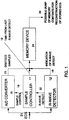
- FIG. 1 shows the basic components of an exemplary system for implementation of the present invention, an analog to digital converter (A/D) (10), sample controller (11), R-wave detector (12) and memory device (24).
- A/D converter (10) must sample the incoming EGG signal 21 at a minimum rate as required by the well-known Nyquist sampling theory.
- the Nyquist rate is proportional to the rate at which the incoming ECG signal varies, i.e., the first order derivative. The faster the incoming ECG signal varies, the more frequently it must be sampled in order to ensure accurate reconstruction.
- the R-Wave detector transmits R-Wave detect 22 to sample controller 11.
- the sample controller 11 controls A/D converter 10 via sample control signal 16.
- the digitized samples 23 and R-Wave detect 18, as well as a time signal 19, are all transmitted to memory device 24 as indicated.
- R-wave detector (12) monitors the incoming ECG signal for the presence of R-waves. Once R-wave detection occurs, sampling and A/D conversion for the associated cardiac cycle begins. The sampling interval is adjusted at predetermined times after R-wave detection since the rate of change of the ECG signal slows considerably at predetermined times after the R-wave is detected.
- An exemplary system with the preferred sample rate is described below with reference to FIG. 2.
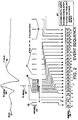
- FIG. 2 shows an ECG signal (21) including R-wave (25) and T-wave (30). Shown in conceptual form beneath the R-wave are ECG samples (23). The samples are arranged into 4 groups (26-29), each of which is taken at a different sampling rate. Memory (24) is also shown in FIG. 2 in conceptual form for purposes of explaining the types and quantities of information which must be stored therein for accurately reconstructing the ECG signal.
- an R-wave (25) is detected and R-wave detector (12) generates the R-wave detect (22) signal.
- R-wave detect (22) is input into sample controller (11) which causes sample controller (11) to generate samples at 12 ms. intervals.
- FIG. 2 shows five such samples immediately prior to the R-wave detect. These first five samples require an analog delay line or any other system capable of storing the ECG prior to the R-wave (e.g., an additional digital register arranged to store past samples) so that when the R-wave is detected, the analog signal just prior to the R-wave detect will still be available. As shown in FIG. 2, five additional closely spaced samples, immediately subsequent to the R-wave detect, are then taken for a total of ten closely spaced samples (26).
- FIG. 2 shows six samples (27) 48 ms. apart. Thereafter, three samples (28) are taken at 96 ms. intervals. Thereafter, all samples have a period of 192 ms. until the last sample prior to the next R-wave detect. It can be appreciated from comparing ECG signal (21) to the samples (23) shown below it that during the flat portion of the ECG signal (21) following T-wave (30), samples are taken at large intervals, while during the rapidly varying portions surrounding R-wave (25), samples are taken much more frequently.
- sampling rules ensure that the ECG signal is sampled at a fixed and nominally short interval (12 ms.) around the R-wave detect point (22), and that the sample period is increased to 48 ms., then to 96 ms., and finally to 192 ms. as the required Nyquist rate for the ECG signal being sampled decreases.
- the sequence of sampling periods for an ECG cycle is denoted herein as a "sample profile.”
- memory (24) Since the stored samples will be used to reconstruct an analog ECG signal, memory (24) must not only store the values of the samples themselves, but must store information sufficient to permit the reconstruction algorithm and/or hardware to determine the proper sampling interval and the time of R-wave detect (22). As show in FIG. 2, memory (24) stores not only the values of the individual digital samples of the ECG signal, but also stores the R-wave detects. Additionally, a value T is stored after each R-wave detect (22), where T indicates the amount of time between the last sample (taken after a 192 ms. interval in the example herein) and the R-wave detect itself.
- the stored information from memory (24) may be utilized to reconstruct the analog ECG signal.
- the stored information is read from memory 24 via electrical path 20 as shown in FIG. 1.
- the individual memory locations have been labeled a - x.
- the time T stored in location c, coupled with the R-wave detect from location b and the ten samples, d through m, can be used to reconstruct the analog ECG signal which immediately surrounds the R-wave detect (22).
- the remaining samples are at known sampling intervals and are simply utilized by a conventional D/A converter to reconstruct the ECG signal.
- the D/A converter may be programmed to specifically implement the technique.
- the purpose of storing the time T is that the sampling interval between any two successive samples is known for the entire ECG signal, except for the sampling interval between sample (29) and the first of the group of samples (26).
- the time T allows this one unknown sampling interval to be determined by the reconstruction algorithm/hardware.
- reconstruction of the analog ECG signal may be done utilizing conventional components in a straightforward manner which will not be described in detail herein.
- the number of samples at the slowest rate varies from cycle to cycle, but recognition of R in effect determines the last sample stored for a cycle.
- an atrial ECG signal may also be monitored and stored in a similar manner.
- An atrial ECG signal would require replacing the R-wave detector described herein with a T-wave detector. Indeed, any portion of the ECG signal may be detected, and the derivative and required sampling rate assumed from the relative time positions of the portion of the signal being sampled and that detected.
- sample profile may be varied at the physician's discretion, and may even be programmable by a telemetric means which are well known in the art and are in wide-spread use for varying pacemaker/defibrillator parameters in known pacemaker systems.
Description
- This invention relates to an improved signal storage and processing system for compressing and reproducing electrocardiogram (ECG) signals.
- Recent advances in implantable pacemakers/defibrillators and Holter monitors allow for digital storage and processing of ECG signals. Typically, an analog ECG signal is sampled and a plurality of digital samples are stored in an internal memory device. The stored samples can be retrieved later and the analog ECG signal can be reconstructed therefrom. Thus, the physician can program the device to sample the ECG output from the heart during certain times and store the samples for later analysis of the ECG signal by the physician.
- It is advantageous to minimize the number of samples of data required to be stored in order to reconstruct the analog ECG signal. One reason is that each time the analog signal is sampled and the sample stored, power is consumed, thereby shortening battery life. Furthermore, many prior art ECG analysis techniques require power consuming digital signal processing algorithms. As the number of samples increases, so does the power consumption of the signal processing algorithm. Finally, since the samples must be stored in memory for later analysis and/or reconstruction of the analog ECG signal, minimizing the number of stored samples minimizes the amount of memory required.
- U.S. Patent No. 4,503,510 to Weaver is directed to a method and apparatus for digital data compression. Compression of the data represents one possible solution to the above problem. Digital signals to be stored are first compressed using a finite-impulse response digital compression filter which generates estimated signal values which are then subtracted from actual signal values to provide a sequence of difference signals. The difference signals are then encoded using a Huffman type encoding technique in order to minimize the number of bits required to store the information. The Weaver arrangement, when compared to a conventional pulse code modulation sampling system, significantly reduces the number of bits of information which must be stored to reconstruct and/or process the ECG signal.
- U.S. Patent No. 4,499,548 to Beebe describes a data compression apparatus which selects for display a data sample of each non-overlapping and successive group of data samples which differs the most in amplitude from the average amplitude of the previous group of data samples, and also selects and displays the data sample of each group which differs the most in amplitude from the data sample selected for display from the previous group. The arrangement of Beebe also significantly reduces the number of data samples which must be stored to reconstruct an analog ECG signal.
- U.S. Patent No. 4,633,884 to Imai, et al., discloses a digital processing system utilizing several digital filters to minimize the number of samples being stored.
- U.S. Patent No. 4,947,858 to Smith discloses an apparatus for data compression of input ECG beats in an electrocardiogram system. The data compression includes the steps of converting the analog ECG beats into digital signals and compressing the digital signals. The step of compressing a beat includes selectively sub-sampling the beat. During sub-sampling, the QRS region is divided into two subregions centered about the QRS peak, and each subregion is sampled at a different rate. As indicated further in this reference, prior compression scheme included both distortion and non-distortion compression schemes. Distortion schemes such as Huffman coding and the Lemple-Ziv method require large memories and therefore are unsuitable for pacemakers which do not have sufficient memory to store up to 24 hours worth of compressed data using these schemes. Distortion compression schemes such as the AZTEC logarithm, and the SAPA compression method result in a loss of the original ECG data and in addition provide either insufficient compression rates to be of any real value, or distort the compressed signals too much and hence the recovered signals are not suitable for visual presentation.
- All of the known prior systems require extensive data processing in order to compress the data to be stored. Thus, in an attempt to minimize the number of samples to be later processed in reconstructing the ECG signal, the ECG samples must be extensively processed before they are stored in the first place. Accordingly, the prior art techniques are, in some sense, self-defeating.
- The above and other problems of the prior art are overcome in accordance with the present invention which relates to a novel digital signal storage and processing technique for storing a digital representation of an ECG signal and for reconstructing the ECG signal at a later time. The present invention utilizes the fact that the ECG signal varies rapidly during certain portions thereof and varies quite slowly during other portions. Moreover, there is a large part of the ECG signal which is nearly constant over a long period of time.
- The present invention utilizes multiple sampling rates which sample the signal at low, medium and high sampling rates, depending upon whether the signal is not varying, varying slowly, or varying rapidly, respectively. The determination of how fast the signal is varying is based upon the relative positions, in time, between the portion being sampled and the R-wave. Unlike conventional variable rate sampling systems, the sampling rate is not determined by continuously calculating estimates of the derivative of the analog signal being sampled. Rather, the derivative, and thus the required sampling rate, are assumed from the relative time positions of the R-wave and the portion of the signal being sampled. Thus, the complex power consuming operation of constantly estimating a derivative is unnecessary.
- The arrangement ensures that the sampling rate is always great enough to reconstruct the signal, but that the sampling rate is never faster than it needs to be during slowly varying portions of the ECG signal being sampled. Thus, the number of required samples is minimized. It should also be noted that other encoding techniques may be further utilized to minimize the number of stored samples even more.
- Accordingly, the invention provides a method for compressing an electrocardiac (ECG) signal composed of successive R-waves as set out in Claim 1, and apparatus for performing such a method as set out in Claim 5.
- Preferred features of the invention are set out in Claims 2 to 4 and 6 to 8.
-
- FIG. 1 depicts in block diagram form the major components to be installed in an implantable pacemaker/defibrillator for implementation of the present invention; and
- FIG. 2 shows an exemplary ECG signal and a digital representation of the ECG signal which is stored in accordance with the technique of the present invention.
- FIG. 1 shows the basic components of an exemplary system for implementation of the present invention, an analog to digital converter (A/D) (10), sample controller (11), R-wave detector (12) and memory device (24). As is well known in the art, A/D converter (10) must sample the
incoming EGG signal 21 at a minimum rate as required by the well-known Nyquist sampling theory. The Nyquist rate is proportional to the rate at which the incoming ECG signal varies, i.e., the first order derivative. The faster the incoming ECG signal varies, the more frequently it must be sampled in order to ensure accurate reconstruction. - The R-Wave detector transmits R-Wave detect 22 to
sample controller 11. Thesample controller 11 controls A/D converter 10 viasample control signal 16. The digitizedsamples 23 and R-Wave detect 18, as well as atime signal 19, are all transmitted tomemory device 24 as indicated. - In operation, R-wave detector (12) monitors the incoming ECG signal for the presence of R-waves. Once R-wave detection occurs, sampling and A/D conversion for the associated cardiac cycle begins. The sampling interval is adjusted at predetermined times after R-wave detection since the rate of change of the ECG signal slows considerably at predetermined times after the R-wave is detected. An exemplary system with the preferred sample rate is described below with reference to FIG. 2.
- FIG. 2 shows an ECG signal (21) including R-wave (25) and T-wave (30). Shown in conceptual form beneath the R-wave are ECG samples (23). The samples are arranged into 4 groups (26-29), each of which is taken at a different sampling rate. Memory (24) is also shown in FIG. 2 in conceptual form for purposes of explaining the types and quantities of information which must be stored therein for accurately reconstructing the ECG signal.
- In operation, an R-wave (25) is detected and R-wave detector (12) generates the R-wave detect (22) signal. R-wave detect (22) is input into sample controller (11) which causes sample controller (11) to generate samples at 12 ms. intervals. FIG. 2 shows five such samples immediately prior to the R-wave detect. These first five samples require an analog delay line or any other system capable of storing the ECG prior to the R-wave (e.g., an additional digital register arranged to store past samples) so that when the R-wave is detected, the analog signal just prior to the R-wave detect will still be available. As shown in FIG. 2, five additional closely spaced samples, immediately subsequent to the R-wave detect, are then taken for a total of ten closely spaced samples (26).
- Following the ten samples at 12 ms. intervals, the sampling interval is increased to 48 ms. FIG. 2 shows six samples (27) 48 ms. apart. Thereafter, three samples (28) are taken at 96 ms. intervals. Thereafter, all samples have a period of 192 ms. until the last sample prior to the next R-wave detect. It can be appreciated from comparing ECG signal (21) to the samples (23) shown below it that during the flat portion of the ECG signal (21) following T-wave (30), samples are taken at large intervals, while during the rapidly varying portions surrounding R-wave (25), samples are taken much more frequently.
- The sampling rules ensure that the ECG signal is sampled at a fixed and nominally short interval (12 ms.) around the R-wave detect point (22), and that the sample period is increased to 48 ms., then to 96 ms., and finally to 192 ms. as the required Nyquist rate for the ECG signal being sampled decreases. The sequence of sampling periods for an ECG cycle is denoted herein as a "sample profile."
- Since the stored samples will be used to reconstruct an analog ECG signal, memory (24) must not only store the values of the samples themselves, but must store information sufficient to permit the reconstruction algorithm and/or hardware to determine the proper sampling interval and the time of R-wave detect (22). As show in FIG. 2, memory (24) stores not only the values of the individual digital samples of the ECG signal, but also stores the R-wave detects. Additionally, a value T is stored after each R-wave detect (22), where T indicates the amount of time between the last sample (taken after a 192 ms. interval in the example herein) and the R-wave detect itself.
- The stored information from memory (24) may be utilized to reconstruct the analog ECG signal. The stored information is read from
memory 24 viaelectrical path 20 as shown in FIG. 1. Specifically, with reference to memory (24) of FIG. 2, the individual memory locations have been labeled a - x. As can be seen from FIG. 2, the time T stored in location c, coupled with the R-wave detect from location b and the ten samples, d through m, can be used to reconstruct the analog ECG signal which immediately surrounds the R-wave detect (22). The remaining samples are at known sampling intervals and are simply utilized by a conventional D/A converter to reconstruct the ECG signal. The D/A converter may be programmed to specifically implement the technique. - The purpose of storing the time T is that the sampling interval between any two successive samples is known for the entire ECG signal, except for the sampling interval between sample (29) and the first of the group of samples (26). The time T allows this one unknown sampling interval to be determined by the reconstruction algorithm/hardware. Once T is known, reconstruction of the analog ECG signal may be done utilizing conventional components in a straightforward manner which will not be described in detail herein. The number of samples at the slowest rate varies from cycle to cycle, but recognition of R in effect determines the last sample stored for a cycle.
- The above describes the preferred embodiment and sampling intervals, although it is obvious that other variations and sample profiles will be apparent to those of ordinary skill in the art. For example, while the embodiment described herein utilizes a ventricular ECG signal, an atrial ECG signal may also be monitored and stored in a similar manner. An atrial ECG signal would require replacing the R-wave detector described herein with a T-wave detector. Indeed, any portion of the ECG signal may be detected, and the derivative and required sampling rate assumed from the relative time positions of the portion of the signal being sampled and that detected.
- It is contemplated that the sample profile may be varied at the physician's discretion, and may even be programmable by a telemetric means which are well known in the art and are in wide-spread use for varying pacemaker/defibrillator parameters in known pacemaker systems.
Claims (8)
- A method for compressing an electrocardiac (ECG) signal composed of successive R-waves (25), by:detecting each R-wave;defining a first region adjacent to said detected R-wave;sampling said first region at a first sampling rate (26);defining a second region adjacent to said first region;sampling said second region at a second sampling rate (27) lower than said first sampling rate; and storing the samples from said sampling steps; characterized in determining a time (T) elapsed between one R-wave and the next R-wave; and storing said time (T) together with said samples to enable the reconstruction of the R-waves from said stored samples.
- The method of Claim 1 wherein said R-waves have peaks, further comprising delaying each R-wave; and defining said first region to extend over a portion of said delayed R-wave, wherein said first region includes samples den before and after said R-wave peak.
- The method of Claim 2 further comprising storing the occurrence of said peak.
- The method of any preceding claim wherein each said R-wave is followed by a T-wave (30), further comprising detecting said period (T) from an end of said T-wave to the next R-wave.
- Apparatus for compressing an electrocardiac (ECG) signal composed of successive R-waves (25), the said apparatus comprising:means (12) for detecting each R-wave;means (11) for defining a first region adjacent the said detected R-wave;means (11) for sampling the first region at a first sampling rate (26);means (11) for defining a second region adjacent the said first region;means (11) for sampling the said second region at a second sampling rate (27) lower than the first sampling rate; andmeans (24) for storing the samples from the sampling steps;
characterised by:means for determining a time (T) elapsed between one R-wave and the next R-wave; andmeans for storing the said time (T) together with the said samples to enable the reconstruction of the R-waves from the said stored samples. - Apparatus according to Claim 5 and comprising means for delaying each R-wave and defining the said first region to extend over a portion of the said delayed R-wave, wherein the said first region includes samples taken before and after a peak of the R-wave.
- Apparatus according to Claim 6 and comprising means for storing the occurrence of a peak in an R-wave.
- Apparatus according to any one of Claims 5 to 7, comprising means for detecting a period (T) between the end of a T-wave and a successive R-wave.
Applications Claiming Priority (2)
| Application Number | Priority Date | Filing Date | Title |
|---|---|---|---|
| AU9244/91 | 1991-11-01 | ||
| AUPK924491 | 1991-11-01 |
Publications (2)
| Publication Number | Publication Date |
|---|---|
| EP0540144A1 EP0540144A1 (en) | 1993-05-05 |
| EP0540144B1 true EP0540144B1 (en) | 1996-12-04 |
Family
ID=3775795
Family Applications (1)
| Application Number | Title | Priority Date | Filing Date |
|---|---|---|---|
| EP92307514A Expired - Lifetime EP0540144B1 (en) | 1991-11-01 | 1992-08-17 | Apparatus and method for electrocardiogram data compression |
Country Status (3)
| Country | Link |
|---|---|
| US (1) | US5263486A (en) |
| EP (1) | EP0540144B1 (en) |
| DE (1) | DE69215646T2 (en) |
Families Citing this family (28)
| Publication number | Priority date | Publication date | Assignee | Title |
|---|---|---|---|---|
| AU3862693A (en) * | 1992-05-18 | 1993-11-25 | Cardiac Pacemakers, Inc. | Method and apparatus for event processing in biological applications |
| US5884245A (en) * | 1993-04-05 | 1999-03-16 | The United States Of America As Represented By The Secretary Of The Navy | Discriminate reduction data acquisition |
| US5857465A (en) * | 1994-08-17 | 1999-01-12 | Seiko Instruments Inc. | Biosignal display apparatus |
| JP3548298B2 (en) * | 1994-08-30 | 2004-07-28 | キヤノン株式会社 | Position shift measuring method and position shift measuring apparatus using the same |
| US5709216A (en) * | 1995-06-07 | 1998-01-20 | Sulzer Intermedics, Inc. | Data reduction of sensed values in an implantable medical device through the use of a variable resolution technique |
| US5602550A (en) * | 1995-06-19 | 1997-02-11 | Bio-Logic Systems Corp. | Apparatus and method for lossless waveform data compression |
| US5791342A (en) * | 1996-09-03 | 1998-08-11 | Telediagnostics Systems, Inc. | Medical data transmission system |
| US5836982A (en) * | 1997-02-19 | 1998-11-17 | Medtronic, Inc. | System and method of data compression and non-linear sampling for implantable and battery-powered devices |
| US20030036746A1 (en) | 2001-08-16 | 2003-02-20 | Avi Penner | Devices for intrabody delivery of molecules and systems and methods utilizing same |
| US6152883A (en) * | 1998-06-23 | 2000-11-28 | Dalhousie University | KLT-based quality controlled compression of a single lead egg |
| US6161043A (en) * | 1999-02-22 | 2000-12-12 | Pacesetter, Inc. | Implantable cardiac device having event recording capability with compression |
| JP3428629B2 (en) * | 1999-03-26 | 2003-07-22 | 日本電気株式会社 | Mobile phone device and power control method thereof |
| US7024248B2 (en) | 2000-10-16 | 2006-04-04 | Remon Medical Technologies Ltd | Systems and methods for communicating with implantable devices |
| US6910084B2 (en) * | 2001-04-30 | 2005-06-21 | Medtronic, Inc | Method and system for transferring and storing data in a medical device with limited storage and memory |
| US6719689B2 (en) * | 2001-04-30 | 2004-04-13 | Medtronic, Inc. | Method and system for compressing and storing data in a medical device having limited storage |
| US7107048B2 (en) * | 2002-01-25 | 2006-09-12 | Chandler Larry S | Inversion-conforming data sets processing |
| US8271093B2 (en) | 2004-09-17 | 2012-09-18 | Cardiac Pacemakers, Inc. | Systems and methods for deriving relative physiologic measurements using a backend computing system |
| US7813808B1 (en) * | 2004-11-24 | 2010-10-12 | Remon Medical Technologies Ltd | Implanted sensor system with optimized operational and sensing parameters |
| US7955268B2 (en) | 2006-07-21 | 2011-06-07 | Cardiac Pacemakers, Inc. | Multiple sensor deployment |
| US7756573B2 (en) * | 2006-09-05 | 2010-07-13 | Cardiac Pacemakers, Inc. | Implantable medical device diagnostic data acquisition and storage |
| US8014851B2 (en) * | 2006-09-26 | 2011-09-06 | Cameron Health, Inc. | Signal analysis in implantable cardiac treatment devices |
| US7930146B2 (en) * | 2007-05-23 | 2011-04-19 | Chandler Larry S | Errors-in-variables data processing including essential weighting of mapped path-oriented deviations with normal component discrimination |
| EP2294979B1 (en) | 2009-09-14 | 2013-12-18 | Imec | Method and electronic medical device for simultaneously measuring an impedance and a biopotential signal |
| US8755868B2 (en) * | 2009-09-14 | 2014-06-17 | Imec | Adaptive sampling |
| EP2298164B1 (en) * | 2009-09-14 | 2013-05-15 | Imec | Cardiac monitoring circuit with adaptive sampling |
| EP2302606B1 (en) * | 2009-09-23 | 2013-06-05 | Dräger Medical GmbH | Method for alarm generation, control device and device for carrying out the method |
| US10238305B2 (en) | 2014-05-30 | 2019-03-26 | Microsoft Technology Licensing, Llc | Dynamic operation of optical heart rate sensors |
| EP3503408A1 (en) | 2017-12-22 | 2019-06-26 | Nokia Technologies Oy | Storing a signal to a memory |
Family Cites Families (7)
| Publication number | Priority date | Publication date | Assignee | Title |
|---|---|---|---|---|
| US4499548A (en) * | 1980-07-02 | 1985-02-12 | Hewlett-Packard Company | Data compression apparatus |
| US4503510A (en) * | 1980-10-31 | 1985-03-05 | Sri International | Method and apparatus for digital data compression |
| JPS59216282A (en) * | 1983-05-24 | 1984-12-06 | Advance Res & Dev Co Ltd | Living body signal processing system |
| US4862897A (en) * | 1985-11-05 | 1989-09-05 | Sound Enhancement Systems, Inc. | Electrocardiogram enhancement system and method |
| US4920489A (en) * | 1987-08-14 | 1990-04-24 | Cardiodata Inc. | Apparatus and method for solid state storage of episodic signals |
| US4882754A (en) * | 1987-08-25 | 1989-11-21 | Digideck, Inc. | Data compression system and method with buffer control |
| US4947858A (en) * | 1989-01-31 | 1990-08-14 | Hewlett-Packard Company | Method and apparatus for data compression in an ECG monitoring system |
-
1992
- 1992-04-28 US US07/876,065 patent/US5263486A/en not_active Expired - Lifetime
- 1992-08-17 EP EP92307514A patent/EP0540144B1/en not_active Expired - Lifetime
- 1992-08-17 DE DE69215646T patent/DE69215646T2/en not_active Expired - Fee Related
Also Published As
| Publication number | Publication date |
|---|---|
| EP0540144A1 (en) | 1993-05-05 |
| US5263486A (en) | 1993-11-23 |
| DE69215646T2 (en) | 1997-04-17 |
| DE69215646D1 (en) | 1997-01-16 |
Similar Documents
| Publication | Publication Date | Title |
|---|---|---|
| EP0540144B1 (en) | Apparatus and method for electrocardiogram data compression | |
| US5215098A (en) | Data compression of cardiac electrical signals using scanning correlation and temporal data compression | |
| US5255186A (en) | Signal averaging of cardiac electrical signals using temporal data compression and scanning correlation | |
| US4458691A (en) | System and method for predicting ventricular tachycardia by adaptive high pass filter | |
| US6599242B1 (en) | Method and apparatus for data compression of heart signals | |
| CN106659900B (en) | Implantable medical device with autocorrelation device and with analysis device for estimating heart rate | |
| US5623935A (en) | Data compression methods and apparatus for use with physiological data | |
| EP0263599B1 (en) | Ecg data compression for storage in a pacemaker memory | |
| US4751931A (en) | Method and apparatus for determining his-purkinje activity | |
| EP1706031B1 (en) | Cardiac monitoring | |
| JP5090924B2 (en) | System for detecting and monitoring T-wave alternation | |
| US6026320A (en) | Heart rate variability as an indicator of exercise capacity | |
| AU654446B2 (en) | Compressed storage of data in cardiac pacemakers | |
| US6301499B1 (en) | Heart rate variability as an indicator of exercise capacity | |
| US5782888A (en) | Method of selecting an operating mode for an implantable medical device | |
| US7657305B2 (en) | Implantable medical device for improved storage of intracardiac electrograms | |
| US20060116592A1 (en) | Method and apparatus for detection and monitoring of T-wave alternans | |
| US4140110A (en) | Systolic pressure determining apparatus and process using integration to determine pulse amplitude | |
| US20040088013A1 (en) | Detection of supraventricular tachycardia with 1:1 atrial to ventricular conduction | |
| US5810739A (en) | Methods and apparatus for classifying cardiac events with an implantable cardiac device | |
| US9008789B2 (en) | System and method for smoothing sampled digital signals | |
| US7460902B2 (en) | Monitoring of atrial activation | |
| EP0834146B1 (en) | Data reduction of sensed values in an implantable medical device through the use of a variable resolution technique | |
| EP1585443A2 (en) | T-wave alternans train spotter | |
| Rey et al. | P-wave detection by digital computer |
Legal Events
| Date | Code | Title | Description |
|---|---|---|---|
| PUAI | Public reference made under article 153(3) epc to a published international application that has entered the european phase |
Free format text: ORIGINAL CODE: 0009012 |
|
| AK | Designated contracting states |
Kind code of ref document: A1 Designated state(s): DE FR GB |
|
| 17P | Request for examination filed |
Effective date: 19931028 |
|
| 17Q | First examination report despatched |
Effective date: 19950207 |
|
| GRAG | Despatch of communication of intention to grant |
Free format text: ORIGINAL CODE: EPIDOS AGRA |
|
| GRAH | Despatch of communication of intention to grant a patent |
Free format text: ORIGINAL CODE: EPIDOS IGRA |
|
| GRAH | Despatch of communication of intention to grant a patent |
Free format text: ORIGINAL CODE: EPIDOS IGRA |
|
| GRAA | (expected) grant |
Free format text: ORIGINAL CODE: 0009210 |
|
| AK | Designated contracting states |
Kind code of ref document: B1 Designated state(s): DE FR GB |
|
| ET | Fr: translation filed | ||
| REF | Corresponds to: |
Ref document number: 69215646 Country of ref document: DE Date of ref document: 19970116 |
|
| PGFP | Annual fee paid to national office [announced via postgrant information from national office to epo] |
Ref country code: GB Payment date: 19970808 Year of fee payment: 6 |
|
| PLBE | No opposition filed within time limit |
Free format text: ORIGINAL CODE: 0009261 |
|
| STAA | Information on the status of an ep patent application or granted ep patent |
Free format text: STATUS: NO OPPOSITION FILED WITHIN TIME LIMIT |
|
| 26N | No opposition filed | ||
| PGFP | Annual fee paid to national office [announced via postgrant information from national office to epo] |
Ref country code: FR Payment date: 19980814 Year of fee payment: 7 |
|
| PG25 | Lapsed in a contracting state [announced via postgrant information from national office to epo] |
Ref country code: GB Free format text: LAPSE BECAUSE OF NON-PAYMENT OF DUE FEES Effective date: 19980817 |
|
| PGFP | Annual fee paid to national office [announced via postgrant information from national office to epo] |
Ref country code: DE Payment date: 19980821 Year of fee payment: 7 |
|
| GBPC | Gb: european patent ceased through non-payment of renewal fee |
Effective date: 19980817 |
|
| PG25 | Lapsed in a contracting state [announced via postgrant information from national office to epo] |
Ref country code: FR Free format text: LAPSE BECAUSE OF NON-PAYMENT OF DUE FEES Effective date: 20000428 |
|
| PG25 | Lapsed in a contracting state [announced via postgrant information from national office to epo] |
Ref country code: DE Free format text: LAPSE BECAUSE OF NON-PAYMENT OF DUE FEES Effective date: 20000601 |
|
| REG | Reference to a national code |
Ref country code: FR Ref legal event code: ST |