EP0539566B1 - System and method for increasing the efficiency of a cyclotron - Google Patents
System and method for increasing the efficiency of a cyclotron Download PDFInfo
- Publication number
- EP0539566B1 EP0539566B1 EP92912146A EP92912146A EP0539566B1 EP 0539566 B1 EP0539566 B1 EP 0539566B1 EP 92912146 A EP92912146 A EP 92912146A EP 92912146 A EP92912146 A EP 92912146A EP 0539566 B1 EP0539566 B1 EP 0539566B1
- Authority
- EP
- European Patent Office
- Prior art keywords
- volume
- cyclotron
- pumping
- ion
- ion source
- Prior art date
- Legal status (The legal status is an assumption and is not a legal conclusion. Google has not performed a legal analysis and makes no representation as to the accuracy of the status listed.)
- Expired - Lifetime
Links
- 238000000034 method Methods 0.000 title claims abstract description 18
- 150000002500 ions Chemical class 0.000 claims abstract description 118
- 239000007789 gas Substances 0.000 claims abstract description 82
- 238000005086 pumping Methods 0.000 claims abstract description 68
- 238000010884 ion-beam technique Methods 0.000 claims abstract description 39
- 230000001133 acceleration Effects 0.000 claims abstract description 37
- 239000001257 hydrogen Substances 0.000 claims abstract description 16
- 229910052739 hydrogen Inorganic materials 0.000 claims abstract description 16
- GPRLSGONYQIRFK-UHFFFAOYSA-N hydron Chemical compound [H+] GPRLSGONYQIRFK-UHFFFAOYSA-N 0.000 claims description 16
- 230000007935 neutral effect Effects 0.000 claims description 14
- -1 hydrogen ions Chemical class 0.000 claims description 10
- 238000004891 communication Methods 0.000 claims description 3
- 125000004435 hydrogen atom Chemical class [H]* 0.000 abstract 2
- 238000006386 neutralization reaction Methods 0.000 abstract 1
- 239000002245 particle Substances 0.000 description 32
- XLYOFNOQVPJJNP-UHFFFAOYSA-N water Chemical compound O XLYOFNOQVPJJNP-UHFFFAOYSA-N 0.000 description 6
- 150000002431 hydrogen Chemical class 0.000 description 4
- 230000005855 radiation Effects 0.000 description 4
- 238000000605 extraction Methods 0.000 description 3
- 238000003860 storage Methods 0.000 description 3
- UFHFLCQGNIYNRP-UHFFFAOYSA-N Hydrogen Chemical compound [H][H] UFHFLCQGNIYNRP-UHFFFAOYSA-N 0.000 description 2
- 238000005452 bending Methods 0.000 description 2
- 238000013461 design Methods 0.000 description 2
- 239000000463 material Substances 0.000 description 2
- 238000010943 off-gassing Methods 0.000 description 2
- 238000004804 winding Methods 0.000 description 2
- 206010028980 Neoplasm Diseases 0.000 description 1
- 238000013459 approach Methods 0.000 description 1
- 201000011510 cancer Diseases 0.000 description 1
- 239000000470 constituent Substances 0.000 description 1
- 238000010276 construction Methods 0.000 description 1
- 230000001419 dependent effect Effects 0.000 description 1
- 239000003814 drug Substances 0.000 description 1
- 230000005684 electric field Effects 0.000 description 1
- 238000005516 engineering process Methods 0.000 description 1
- 239000011888 foil Substances 0.000 description 1
- 238000004519 manufacturing process Methods 0.000 description 1
- 238000012986 modification Methods 0.000 description 1
- 230000004048 modification Effects 0.000 description 1
- 230000002285 radioactive effect Effects 0.000 description 1
- 239000013077 target material Substances 0.000 description 1
- 238000011282 treatment Methods 0.000 description 1
Images

Classifications
-
- H—ELECTRICITY
- H05—ELECTRIC TECHNIQUES NOT OTHERWISE PROVIDED FOR
- H05H—PLASMA TECHNIQUE; PRODUCTION OF ACCELERATED ELECTRICALLY-CHARGED PARTICLES OR OF NEUTRONS; PRODUCTION OR ACCELERATION OF NEUTRAL MOLECULAR OR ATOMIC BEAMS
- H05H13/00—Magnetic resonance accelerators; Cyclotrons
Definitions
- This invention relates to an improved system and method for increasing the efficiency of a cyclotron and more particularly a negative hydrogen (H - ) ion cyclotron.
- Cyclotrons have been known for many years. Since the beginning of the atomic age, many uses have been developed for particle accelerators, of which a cyclotron is one type. Particle accelerators are used to accelerate subatomic particles or ions, and more particularly to produce a beam of accelerated subatomic particles. The beam of accelerated (i.e., high energy) particles can be used to bombard a variety of target materials to produce radioactive isotopes having a variety of uses. For example, various isotopes produced in this manner have been used in medicine as tracers which are injected into the body, and in radiation treatments for cancer.
- a cyclotron is a type of particle accelerator in which charged particles are accelerated through a substantially spiral path which increases in radius through the range of acceleration.
- the particles are accelerated using the forces of electrical potential and magnetic fields.
- the particles are accelerated as they pass through a gap between two electrodes, the first electrode having the same (sign) charge as the particle, e.g., negative (-), and the second electrode having the opposite (sign) charge as the particle, e.g., positive (+) ; the first electrode tending to push or repel the particle across the gap and the second electrode tending to pull or attract the particle across the gap.
- the path of the accelerated particle is then bent by a magnetic field into a spiral path which tends to cause the particle to be directed back across the gap.
- the cyclotron of the present invention is a negative ion cyclotron.
- the charged particles are accelerated within a substantially planar volume (hereinafter referred to as the "acceleration region") within the cyclotron.
- This volume must be highly evacuated to remove undesirable gaseous particles which could interact with the accelerated particles, resulting in a reaction which would cause the accelerated particle to be "lost".
- a hydrogen gas (H 2 ) molecule in the acceleration region of the cyclotron can strip off the weakly-bound second electron of the H - ion. When the ion loses this electron, it becomes a neutral particle which is no longer affected by the acceleration gaps or magnetic field within the cyclotron.
- the accelerated neutral particle "flies off" in a tangential direction and never reaches the end of the spiral acceleration path where the beam of accelerated particles is extracted from the cyclotron.
- the accelerated neutral particle can cause an undesirable reaction in the material in which it is subsequently absorbed because of its high energy.
- ions can be stripped by water vapor molecules which are produced by "outgassing" of the cyclotrons inner surfaces.
- the ion source is placed outside of the cyclotron acceleration chamber where it can be separately pumped to prevent residual H 2 gas from reaching the acceleration region of the cyclotron volume.
- the ion source is placed outside of the cyclotron acceleration chamber where it can be separately pumped to prevent residual H 2 gas from reaching the acceleration region of the cyclotron volume.
- Document US-A-5 017 882 discloses a proton/neutron source incorporating a cyclotron with a cylindrical superconducting magnet. Thereby, particles are accelerated, removed from a spiral path and then passed through the proton storage ring. Entering the proton storage ring, the particles are stripped of the electrons so that they become positively charged protons circulating continuously round the storage ring.
- Document US-A-3 641 446 discloses a device for the production of a multiple energy proton beam comprising a negative hydrogen ion cyclotron with stripping foils which are placed at different radial and azimuthal positions.
- the present invention provides a system and method for minimizing loss of efficiency in a negative hydrogen ion cyclotron caused by gas stripping of the negative hydrogen ions within the acceleration region.
- the system comprises a negative hydrogen ion cyclotron which defines a cyclotron volume, a negative hydrogen ion (H - ) source which defines a H - ion source volume, and a vacuum system.
- the vacuum system includes a main pump for pumping, i.e., evacuating, the cyclotron volume, and an ion source pump for separately evacuating the H - ion source volume.
- a passageway is provided between and communicating with the ion source volume and the ion source pump, this passageway having a relatively high gas conductance to facilitate the evacuation of H 2 gas from the ion source volume by the ion source pump.
- Another passageway is provided between and communicating with the cyclotron volume and the main pump which facilitates the evacuation of the cyclotron volume, the gas conductance of the passageway and the capacity of the main pump being selected such that the equilibrium pressure in the cyclotron volume is many times less than that in the ion source volume. In the preferred embodiment, it has been calculated that the equilibrium pressure in the ion source volume will be thirty thousand (3 X 10 4 ) times greater than that in the cyclotron volume.
- Yet another passageway is provided between and communicating with the ion source volume and the cyclotron volume, the gas conductance of which is sufficiently low that the flow of H 2 gas from the ion source volume into the cyclotron volume is minimal, while still permitting a H - ion beam to pass through it from the ion source volume to the cyclotron volume.
- a system and method of increasing the efficiency of the cyclotron and reducing neutral particle radiation is provided by minimizing the residual H 2 gas passing from the ion source volume into the cyclotron volume, where such gas could strip the negative hydrogen ions in the acceleration region.
- the system further includes a pumping volume in communication with the ion source volume and the cyclotron volume.
- Passageways are provided in communication between the ion source volume and the pumping volume, and between the pumping volume and the cyclotron volume, respectively, such passageways having a sufficiently low gas conductance that the flow of residual H 2 gas through them is minimal, while still permitting an ion beam to pass through them and into the cyclotron.
- Yet another passageway is provided for separately communicating between the pumping volume and the ion source pump, such passageway having a sufficiently large gas conductance to permit evacuation of residual H 2 gas from the pumping volume. Accordingly, a system and method is provided in the preferred embodiment whereby residual H 2 gas is removed from the pumping volume.
- a system and method is provided in the preferred embodiment whereby residual H 2 gas from the ion source volume is evacuated in two stages before it can enter the cyclotron volume, thereby increasing the efficiency of the system.
- the radio-frequency system is operated at a frequency four times that of the ion beam orbit frequency, in a preferred embodiment. It will be recognized, however, that other integral multiples of the ion beam orbit could be chosen as well.
- Figure 1 illustrates a cyclotron vacuum pumping schematic according to a preferred embodiment of the present invention.
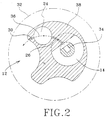
- Figure 2 is a cross-sectional drawing of a central region of the cyclotron of the present invention depicting the position of the components of the pumping schematic of Figure 1.
- a system and method for minimizing loss of efficiency in a negative hydrogen ion (H - ) cyclotron caused by gas stripping of the H - ions in the acceleration region of the cyclotron is diagrammatically illustrated at 10 in Figure 1.
- the system 10 includes a negative hydrogen ion cyclotron having a cyclotron volume 12 which further defines an acceleration region (not shown) of the cyclotron, and an ion source volume 14.
- a negative hydrogen ion cyclotron having a cyclotron volume 12 which further defines an acceleration region (not shown) of the cyclotron, and an ion source volume 14.
- the aforementioned means for producing an H - ion beam from supplied H 2 gas will be located proximate the cyclotron center and on the plane of acceleration in order to start the said H - beam on the plane of acceleration.
- This ion source is provided with a negative bias to aid in extracting the negative ions from the source and providing them with the necessary velocity and radius of curvature to move through the ion passageway.
- a main vacuum pump 16 which evacuates the cyclotron volume 12 via the main vacuum passageway 18.
- the gas conductance in passageway 18 is indicated as C 5 .
- An ion source pump 20 evacuates the ion source volume 14 via the source volume vacuum passageway 22 which has a sufficiently large gas conductance C 3 to permit evacuation of residual hydrogen gas from the ion source volume 14.
- the ion source volume 14 surrounding the ion source is positioned near the center of the cyclotron.
- the ion beam produced in the ion source is directed from the ion source volume to the pumping volume 24 via the first ion passageway 26 which has a much smaller gas conductance C 1 than the source volume vacuum passageway 22, thereby minimizing the amount of residual H 2 gas which passes through it.
- a small but significant amount of residual H 2 gas does pass from the ion source volume 14 into the pumping volume 24 through the passageway 26 along with the ion beam.
- the pumping volume 24 is evacuated by the ion source pump 20 via the pumping volume vacuum passageway 28 which has a relatively large gas conductance C 4 to facilitate the evacuation of this residual H 2 gas in the pumping volume 24.
- a second ion passageway 30 is provided through which the ion beam is directed from the pumping volume 24 into the cyclotron volume 12 proximate the center of the acceleration region of the cyclotron.
- the gas conductance C 2 of the second ion passageway 30 is low enough that the amount of residual H 2 gas passing from the pumping volume into the cyclotron volume is minimal.
- the path of the ion beam and residual H 2 gas through the passageways 26 and 30 is indicated by the arrows 27 and 31, respectively, in Figure 1. It will also be noted that the flow of gases evacuated from the ion source volume 14, pumping volume 24, and the cyclotron volume 12, is indicated by the arrows 23, 29 and 19, respectively.
- a system 10 is provided whereby residual H 2 gas passing into the cyclotron volume 12 from the ion source volume 14 is minimized, thereby increasing efficiency of a negative hydrogen ion (H - ) cyclotron by reducing gas stripping of ions in the acceleration region of the cyclotron.
- H - cyclotron utilizing the features of the above-described invention can be constructed in a number of ways.
- the radio-frequency generating system is made up of an RF generator 21 that is fed by a voltage supply 25. This causes the alternation of the potential applied to the electrodes 15, 17 that provide acceleration to ions within the cyclotron volume 12.
- an ion source 34 within the ion source volume 14 is connected to a negative voltage supply 35 such that the ion source 34 is negatively biased.
- FIG. 2 a cross-sectional mid-plane view of a small section, defined by the diagrammatic circle 32, of the central region, i.e., acceleration region, of a cyclotron employing this preferred embodiment of the present invention is shown. From this figure, it can be seen that the ion beam produced by an ion source 34 passes along path 36 from the ion source volume 14 into the pumping volume 24 through the ion passageway 26, and from the pumping volume 24 into the cyclotron volume 12 through the ion passageway 30, all in the mid-plane of the cyclotron where it is accelerated. Because the ion beam enters the acceleration region in the same plane as that in which it is accelerated, means for bending the beam into that plane are not required as in the case of an externally positioned ion source.
- the magnetic field of a cyclotron is typically created by electromagnetic coils together with magnet pole pieces.
- any of the known types of electromagnetic coils can be used. Although the coils are not shown in Figure 2, the position of the coils will be known to persons skilled in the art.
- the type of coil winding includes, for example, coil windings fabricated from superconducting materials.
- the ion passageways 26 and 30, respectively follow a curved path in the mid-plane of the cyclotron. This is necessary because the H - ions have velocity provided by a negative potential on the ion source. This velocity and the negative charge interact with the magnetic field of the cyclotron, thereby bending the ion beam through this path as it travels into the cyclotron volume.
- the accelerating field of the cyclotron is created by a radio-frequency system, as is well-known to those skilled in the art.
- the radio-frequency system of the cyclotron of the present invention will be operated at a frequency four times greater than the ion beam orbital frequency. This is a departure from the practice of conventional cyclotrons, and forms one of the features of the present invention. Operation at this higher frequency is made possible by the application of a negative bias to the ion source.
- an H - cyclotron constructed in accordance with the above-described preferred embodiment can be designed to achieve a ninety-seven percent (97%) efficiency, i.e., only three percent (3%) of the ions injected into the center of the acceleration region of the cyclotron are lost to gas stripping before being extracted.
- H 2 O water
- H 2 O water
- the principal residual gas constituents and their sources are H 2 , from the ion source, and H 2 O, from outgassing of the cyclotron inner surfaces.
- H 2 the principal residual gas constituents and their sources
- H 2 O from outgassing of the cyclotron inner surfaces.
- the indicated efficiency is obtained by constructing the cyclotron in accordance with the present invention in which: C 1 is the gas conductance of the first ion passageway 26; C 2 is the gas conductance of the second ion passageway 30; C 3 is the gas conductance of the ion source volume passageway 22; C 4 is the gas conductance of the pumping volume vacuum passageway 28; C 5 is the gas conductance of the main vacuum passageway 18; P 1 is the equilibrium pressure in the ion source volume 14; P 2 is the equilibrium pressure in the pumping volume 24; and P 3 is the equilibrium pressure in the cyclotron volume 12.
- the indicated passageways are dimensioned to have the gas conductances shown in Table I, shown below.
- the pressures P 1 - P 3 can be calculated.
- the H 2 pressure in the cyclotron volume 12 is well below the goal of 5 x 10 -7 torr required to achieve an efficiency of 97%.
- the applicant is aware of technology (not the subject of this invention) which will permit the achievement of the goal of providing a cyclotron in which an H 2 O base pressure of less than 1.33 . 10 -5 Pa (1 X 10 -7 torr) is obtained.
- a system and method is provided by the present invention whereby the efficiency of a negative hydrogen ion cyclotron is increased by minimizing gas stripping of ions in the acceleration region of the cyclotron. Further, by minimizing gas stripping of ions, undesirable neutral particle radiation is significantly reduced. Because of the improved efficiency, a smaller, lower weight negative hydrogen ion cyclotron is provided which can be built at a lower cost than previous cyclotrons having a comparable output. Further savings in weight, size, and cost will be realized through the operating of the radio-frequency system of the cyclotron of the present invention at a frequency four times greater than the ion beam orbital frequency.
Landscapes
- Physics & Mathematics (AREA)
- Engineering & Computer Science (AREA)
- Plasma & Fusion (AREA)
- Spectroscopy & Molecular Physics (AREA)
- Particle Accelerators (AREA)
- Photoreceptors In Electrophotography (AREA)
- Crystals, And After-Treatments Of Crystals (AREA)
- Pulleys (AREA)
- Electrotherapy Devices (AREA)
- Electron Sources, Ion Sources (AREA)
- Transition And Organic Metals Composition Catalysts For Addition Polymerization (AREA)
- Manufacturing Of Steel Electrode Plates (AREA)
Abstract
Description
- This invention relates to an improved system and method for increasing the efficiency of a cyclotron and more particularly a negative hydrogen (H-) ion cyclotron.
- Cyclotrons have been known for many years. Since the beginning of the atomic age, many uses have been developed for particle accelerators, of which a cyclotron is one type. Particle accelerators are used to accelerate subatomic particles or ions, and more particularly to produce a beam of accelerated subatomic particles. The beam of accelerated (i.e., high energy) particles can be used to bombard a variety of target materials to produce radioactive isotopes having a variety of uses. For example, various isotopes produced in this manner have been used in medicine as tracers which are injected into the body, and in radiation treatments for cancer.
- A cyclotron is a type of particle accelerator in which charged particles are accelerated through a substantially spiral path which increases in radius through the range of acceleration. The particles are accelerated using the forces of electrical potential and magnetic fields. The particles are accelerated as they pass through a gap between two electrodes, the first electrode having the same (sign) charge as the particle, e.g., negative (-), and the second electrode having the opposite (sign) charge as the particle, e.g., positive (+) ; the first electrode tending to push or repel the particle across the gap and the second electrode tending to pull or attract the particle across the gap. The path of the accelerated particle is then bent by a magnetic field into a spiral path which tends to cause the particle to be directed back across the gap. By alternately changing the polarity of the electrodes by means of a radio-frequency generating system, the particles are accelerated with each crossing of the gap, thereby increasing the radius of the spiral path of the accelerated particles. Most prior art cyclotrons use positively charged particles. The cyclotron of the present invention is a negative ion cyclotron.
- The charged particles are accelerated within a substantially planar volume (hereinafter referred to as the "acceleration region") within the cyclotron. This volume must be highly evacuated to remove undesirable gaseous particles which could interact with the accelerated particles, resulting in a reaction which would cause the accelerated particle to be "lost". For example, in a cyclotron used to accelerate negative hydrogen (H-) ions, a hydrogen gas (H2) molecule in the acceleration region of the cyclotron can strip off the weakly-bound second electron of the H- ion. When the ion loses this electron, it becomes a neutral particle which is no longer affected by the acceleration gaps or magnetic field within the cyclotron. As a result, the accelerated neutral particle "flies off" in a tangential direction and never reaches the end of the spiral acceleration path where the beam of accelerated particles is extracted from the cyclotron. In addition to being lost from the beam of accelerated particles, the accelerated neutral particle can cause an undesirable reaction in the material in which it is subsequently absorbed because of its high energy.
- In light of the above, it can be seen that the quality of the vacuum achieved within the cyclotron plays a key role in the efficiency of the cyclotron. Residual gas molecules present in the acceleration region of the cyclotron act as stripping centers that can remove negative ions from the accelerating beam as described above. Previous H- cyclotrons have suffered from relatively low efficiency because residual H2 gas molecules from the H- ion source, injected into the cyclotron along with the ions to be accelerated, stripped some of the ions before being removed by the cyclotron vacuum system.
- In addition to the stripping caused by residual H2 gas molecules, ions can be stripped by water vapor molecules which are produced by "outgassing" of the cyclotrons inner surfaces.
- In some H- cyclotrons, the ion source is placed outside of the cyclotron acceleration chamber where it can be separately pumped to prevent residual H2 gas from reaching the acceleration region of the cyclotron volume. With this approach, it is necessary to inject the ion beam into the cyclotron along its magnetic axis. The beam then must be bent into the mid-plane of the cyclotron where it is subsequently accelerated. This method involves additional cost and complexity.
- Document US-A-5 017 882 discloses a proton/neutron source incorporating a cyclotron with a cylindrical superconducting magnet. Thereby, particles are accelerated, removed from a spiral path and then passed through the proton storage ring. Entering the proton storage ring, the particles are stripped of the electrons so that they become positively charged protons circulating continuously round the storage ring.
- Document US-A-3 641 446 discloses a device for the production of a multiple energy proton beam comprising a negative hydrogen ion cyclotron with stripping foils which are placed at different radial and azimuthal positions.
- It is the object of the present invention to provide a system and a method for minimising loss of efficiency in the negative hydrogen ion cyclotron caused by gas stripping of the ions within the accelerated region of the cyclotron.
- This object is solved with the negative hydrogen ion cyclotron system and the method of claims 1 and 6, respectively. Advantageous embodiments of the invention are defined in the dependent claims.
- It is a further aspect of the present invention to provide a system and method for minimizing neutral particle radiation in a negative hydrogen ion cyclotron caused by gas stripping of accelerated ions within the accelerated region of the cyclotron.
- It is still another aspect of the present invention to provide a system and method whereby a smaller, lower weight negative hydrogen ion cyclotron can be provided at a relatively low cost.
- It is another aspect of the present invention to provide such a cyclotron with a negatively biased axially-inserted hydrogen negative ion source located near the cyclotron center and substantially on the plane of acceleration.
- It is still another aspect of the present invention to provide such a cyclotron with a radio-frequency system operating at four times the orbiting frequency of the ion beam.
- It is a further aspect of the present invention to provide such a cyclotron with a substantially higher acceleration efficiency than conventional H- cyclotrons.
- Other objects and advantages will be accomplished by the present invention which provides a system and method for minimizing loss of efficiency in a negative hydrogen ion cyclotron caused by gas stripping of the negative hydrogen ions within the acceleration region. The system comprises a negative hydrogen ion cyclotron which defines a cyclotron volume, a negative hydrogen ion (H-) source which defines a H- ion source volume, and a vacuum system. The vacuum system includes a main pump for pumping, i.e., evacuating, the cyclotron volume, and an ion source pump for separately evacuating the H- ion source volume. A passageway is provided between and communicating with the ion source volume and the ion source pump, this passageway having a relatively high gas conductance to facilitate the evacuation of H2 gas from the ion source volume by the ion source pump. Another passageway is provided between and communicating with the cyclotron volume and the main pump which facilitates the evacuation of the cyclotron volume, the gas conductance of the passageway and the capacity of the main pump being selected such that the equilibrium pressure in the cyclotron volume is many times less than that in the ion source volume. In the preferred embodiment, it has been calculated that the equilibrium pressure in the ion source volume will be thirty thousand (3 X 10⁴) times greater than that in the cyclotron volume. Yet another passageway is provided between and communicating with the ion source volume and the cyclotron volume, the gas conductance of which is sufficiently low that the flow of H2 gas from the ion source volume into the cyclotron volume is minimal, while still permitting a H- ion beam to pass through it from the ion source volume to the cyclotron volume.
- Accordingly, a system and method of increasing the efficiency of the cyclotron and reducing neutral particle radiation is provided by minimizing the residual H2 gas passing from the ion source volume into the cyclotron volume, where such gas could strip the negative hydrogen ions in the acceleration region.
- In the preferred embodiment, the system further includes a pumping volume in communication with the ion source volume and the cyclotron volume. Passageways are provided in communication between the ion source volume and the pumping volume, and between the pumping volume and the cyclotron volume, respectively, such passageways having a sufficiently low gas conductance that the flow of residual H2 gas through them is minimal, while still permitting an ion beam to pass through them and into the cyclotron. Yet another passageway is provided for separately communicating between the pumping volume and the ion source pump, such passageway having a sufficiently large gas conductance to permit evacuation of residual H2 gas from the pumping volume. Accordingly, a system and method is provided in the preferred embodiment whereby residual H2 gas is removed from the pumping volume. Accordingly, a system and method is provided in the preferred embodiment whereby residual H2 gas from the ion source volume is evacuated in two stages before it can enter the cyclotron volume, thereby increasing the efficiency of the system. And, further, in order to reduce the size of the cyclotron magnet and radio-frequency system, the radio-frequency system is operated at a frequency four times that of the ion beam orbit frequency, in a preferred embodiment. It will be recognized, however, that other integral multiples of the ion beam orbit could be chosen as well.
- The above-mentioned features of the present invention will become more clearly understood from the following detailed description of the invention read together with the drawings in which:
- Figure 1 illustrates a cyclotron vacuum pumping schematic according to a preferred embodiment of the present invention.
- Figure 2 is a cross-sectional drawing of a central region of the cyclotron of the present invention depicting the position of the components of the pumping schematic of Figure 1.
- A system and method for minimizing loss of efficiency in a negative hydrogen ion (H-) cyclotron caused by gas stripping of the H- ions in the acceleration region of the cyclotron is diagrammatically illustrated at 10 in Figure 1. The
system 10 includes a negative hydrogen ion cyclotron having acyclotron volume 12 which further defines an acceleration region (not shown) of the cyclotron, and anion source volume 14. Though not a part of the present invention, it will be appreciated by those skilled in the art that means for producing an H- ion beam from supplied H2 gas, indicated by thearrow 13 in Figure 1, within theion source volume 14 will be provided. It is a feature of the present invention that the aforementioned means for producing an H- ion beam from supplied H2 gas will be located proximate the cyclotron center and on the plane of acceleration in order to start the said H- beam on the plane of acceleration. This ion source is provided with a negative bias to aid in extracting the negative ions from the source and providing them with the necessary velocity and radius of curvature to move through the ion passageway. - Still referring to Figure 1, a
main vacuum pump 16 is provided which evacuates thecyclotron volume 12 via themain vacuum passageway 18. The gas conductance inpassageway 18 is indicated as C5. Anion source pump 20 evacuates theion source volume 14 via the sourcevolume vacuum passageway 22 which has a sufficiently large gas conductance C3 to permit evacuation of residual hydrogen gas from theion source volume 14. As will be discussed with regard to Figure 2, theion source volume 14 surrounding the ion source is positioned near the center of the cyclotron. The ion beam produced in the ion source is directed from the ion source volume to the pumpingvolume 24 via thefirst ion passageway 26 which has a much smaller gas conductance C1 than the sourcevolume vacuum passageway 22, thereby minimizing the amount of residual H2 gas which passes through it. However, a small but significant amount of residual H2 gas does pass from theion source volume 14 into the pumpingvolume 24 through thepassageway 26 along with the ion beam. The pumpingvolume 24 is evacuated by theion source pump 20 via the pumpingvolume vacuum passageway 28 which has a relatively large gas conductance C4 to facilitate the evacuation of this residual H2 gas in the pumpingvolume 24. Asecond ion passageway 30 is provided through which the ion beam is directed from the pumpingvolume 24 into thecyclotron volume 12 proximate the center of the acceleration region of the cyclotron. The gas conductance C2 of thesecond ion passageway 30 is low enough that the amount of residual H2 gas passing from the pumping volume into the cyclotron volume is minimal. The path of the ion beam and residual H2 gas through thepassageways arrows ion source volume 14, pumpingvolume 24, and thecyclotron volume 12, is indicated by thearrows - In light of the foregoing, it will be appreciated that a
system 10 is provided whereby residual H2 gas passing into thecyclotron volume 12 from theion source volume 14 is minimized, thereby increasing efficiency of a negative hydrogen ion (H-) cyclotron by reducing gas stripping of ions in the acceleration region of the cyclotron. It will be appreciated by those skilled in the art that a H- cyclotron utilizing the features of the above-described invention can be constructed in a number of ways. - Illustrated in schematic form in Figure 1 are some of the substantially conventional portions of the present cyclotron. For example, the radio-frequency generating system is made up of an
RF generator 21 that is fed by avoltage supply 25. This causes the alternation of the potential applied to theelectrodes cyclotron volume 12. Also shown in this figure is anion source 34 within theion source volume 14, with this ion source being connected to anegative voltage supply 35 such that theion source 34 is negatively biased. - Referring to Figure 2, a cross-sectional mid-plane view of a small section, defined by the
diagrammatic circle 32, of the central region, i.e., acceleration region, of a cyclotron employing this preferred embodiment of the present invention is shown. From this figure, it can be seen that the ion beam produced by anion source 34 passes alongpath 36 from theion source volume 14 into the pumpingvolume 24 through theion passageway 26, and from the pumpingvolume 24 into thecyclotron volume 12 through theion passageway 30, all in the mid-plane of the cyclotron where it is accelerated. Because the ion beam enters the acceleration region in the same plane as that in which it is accelerated, means for bending the beam into that plane are not required as in the case of an externally positioned ion source. - The magnetic field of a cyclotron is typically created by electromagnetic coils together with magnet pole pieces. In the cyclotron of the present invention, any of the known types of electromagnetic coils can be used. Although the coils are not shown in Figure 2, the position of the coils will be known to persons skilled in the art. The type of coil winding includes, for example, coil windings fabricated from superconducting materials.
- It will be noted that the
ion passageways - The accelerating field of the cyclotron is created by a radio-frequency system, as is well-known to those skilled in the art. However, in order to reduce the size of the cyclotron magnet and radio-frequency system, the radio-frequency system of the cyclotron of the present invention will be operated at a frequency four times greater than the ion beam orbital frequency. This is a departure from the practice of conventional cyclotrons, and forms one of the features of the present invention. Operation at this higher frequency is made possible by the application of a negative bias to the ion source. Otherwise, if this very rapidly varying potential were used to both extract ions from the source and to accelerate the ions across the first acceleration gap (as in conventional cyclotrons), a much lower ion beam intensity would be realized. This is due to the fact that the RF potential can reverse itself before the ion completely crosses the acceleration gap. Only those ions which are extracted from the source early in the RF cycle successfully cross the gap. The intensity of a beam of ions extracted early in the RF cycle would be low since the electric field across the gap would be low at this time. The negatively biased ion source of the present invention avoids this problem.
- It has been determined that an H- cyclotron constructed in accordance with the above-described preferred embodiment can be designed to achieve a ninety-seven percent (97%) efficiency, i.e., only three percent (3%) of the ions injected into the center of the acceleration region of the cyclotron are lost to gas stripping before being extracted. This conclusion follows from the knowledge that, in previous cyclotrons, the fraction of H- ions that do not undergo gas stripping within a radius R from the center of the cyclotron (i.e., those that survive) has been found to obey the empirical relation:

- In a cyclotron design under consideration, the principal residual gas constituents and their sources are H2, from the ion source, and H2O, from outgassing of the cyclotron inner surfaces. By constructing the cyclotron in accordance with the present invention, an effective H2 residual pressure of 1.33.10-4Pa (1 X 10⁻⁶ torr) can be achieved by limiting the true H2 pressure to 6.65.10-5 Pa (5 X 10⁻⁷ torr, and the H2O pressure to 1.33.10-5 Pa (1 X 10⁻⁷ torr). In a cyclotron having a beam radius at extraction of 0.7m, and an energy gain per turn of 0.2MeV, the overall extraction efficiency obtained will be:

- Thus, as indicated above, only three percent (3%) of the injected ions will be lost to gas stripping before being extracted.
- Referring back to Figure 1, the indicated efficiency is obtained by constructing the cyclotron in accordance with the present invention in which: C1 is the gas conductance of the
first ion passageway 26; C2 is the gas conductance of thesecond ion passageway 30; C3 is the gas conductance of the ionsource volume passageway 22; C4 is the gas conductance of the pumpingvolume vacuum passageway 28; C5 is the gas conductance of themain vacuum passageway 18; P1 is the equilibrium pressure in theion source volume 14; P2 is the equilibrium pressure in the pumpingvolume 24; and P3 is the equilibrium pressure in thecyclotron volume 12. The indicated passageways are dimensioned to have the gas conductances shown in Table I, shown below. Given the gas conductances, the pressures P1 - P3 can be calculated. Table I below, lists the approximate gas conductance values for both 12 MeV and 30 MeV cyclotron designs, along with the resulting pressures, assuming that the H2 input flow rates (shown at 13 in Figure 1) are as indicated (1 sccm = 0.012 torr 1 s-1 = 1.59 Pa.ℓ.s-1).

- Thus, the H2 pressure in the
cyclotron volume 12 is well below the goal of 5 x 10⁻⁷ torr required to achieve an efficiency of 97%. The applicant is aware of technology (not the subject of this invention) which will permit the achievement of the goal of providing a cyclotron in which an H2O base pressure of less than 1.33.10-5 Pa (1 X 10⁻⁷ torr) is obtained. - Therefore, a system and method is provided by the present invention whereby the efficiency of a negative hydrogen ion cyclotron is increased by minimizing gas stripping of ions in the acceleration region of the cyclotron. Further, by minimizing gas stripping of ions, undesirable neutral particle radiation is significantly reduced. Because of the improved efficiency, a smaller, lower weight negative hydrogen ion cyclotron is provided which can be built at a lower cost than previous cyclotrons having a comparable output. Further savings in weight, size, and cost will be realized through the operating of the radio-frequency system of the cyclotron of the present invention at a frequency four times greater than the ion beam orbital frequency.
- While a preferred embodiment has been shown and described, it will be understood that there is no intent to limit the invention to such disclosure, but rather it is intended to cover all modifications and alternate constructions falling within the scope of the appended claims.
Claims (8)
- A negative hydrogen ion cyclotron system (10) having improved efficiency by reducing collisions of hydrogen ions with residual neutral atoms and molecules within said cyclotron, which comprises:a cyclotron having a cyclotron volume (12), a magnetic system for producing a magnetic field for the deflection of ions within said cyclotron volume, and a radio-frequency system for accelerating said ions within said cyclotron volume, said cyclotron volume having an acceleration plane defined by said magnet system and said radio-frequency system in which said hydrogen ions are accelerated and deflected in a spiral path at an ion orbital frequency;pumping means (16) connected to said cyclotron volume by a first vacuum pumping passageway (18) having a selected gas conductance for producing a selected vacuum within said cyclotron volume (12) to minimize collisions between hydrogen ions and residual molecules within said cyclotron volume (12);an ion source volume (14) disposed within said cyclotron on said acceleration plane proximate a center of said spiral path;an ion source (34) biased by a negative voltage supply (35) disposed within said ion source volume (14) for producing negative hydrogen ions for acceleration within said cyclotron volume (12) by said radio-frequency system; characterized byfurther pumping means (20) connected to said ion source volume (14) through a further vacuum pumping passageway (22) having a selected gas conductance;an ion beam passageway (26,30) communicating between said ion source volume (34) and said cyclotron volume (12) for conveying ions into said cyclotron volume for acceleration by said radio-frequency system, said ion beam passageway having a selected gas conductance less than said gas conductance of said first and further vacuum pumping passageways whereby said further pumping means (20) preferentially removes said neutral atoms and molecules from said ion source volume, said ion beam passageway configured to pass said ions along an arc determined by said negative voltage source and said magnetic field.
- The system of Claim 1 further comprising a pumping volume (24) disposed within said cyclotron intermediate, and in communication with, said ion source volume (14) and said cyclotron volume (12), wherein said ion beam passageway has a first portion (26) communicating between said ion source volume (14) and said pumping (24) volume and a second portion (30) communicating between said pumping source volume (24) and said cyclotron volume (12), and wherein said further pumping means (20) is connected to said pumping volume (24) through a third vacuum pumping passageway (28) having a selected gas conductance substantially equal to said further vacuum pumping passageway.
- The system of Claim 1 wherein said gas conductance of said ion beam passageway (26,30) is about 2 X 10⁻² to about 15 X 10-2 times said gas conductance of said vacuum pumping passageways.
- A negative hydrogen ion cyclotron of claims 1 and 3, further comprising:a pumping volume (24) disposed within said cyclotron on said acceleration plane proximate said center of said spiral path; andfurther pumping means (20) connected through second and third vacuum pumping passageways (22, 28) to said ion source volume (14) and said pumping volume (24), respectively said second and third vacuum pumping passageways (22, 28) each having a selected gas conductance; and whereinsaid ion beam passageway (26, 30) comprisesa first ion beam passageway (26) communicating between said ion source volume (14) and said pumping volume (24) for conveying ions from said ion source (34) into said pumping volume (24), said first ion beam passageway (26) having a selected gas conductance substantially less than said gas conductance of said second and third vacuum pumping passageways (22, 28) whereby said further pumping means (20) preferentially removes said neutral atoms and molecules from said ion source volume (14); anda second ion beam passageway (30) communicating between said pumping volume (24) and said cyclotron volume (12) for conveying ions from said pumping volume (24) into said cyclotron volume (12) for acceleration by said radio-frequency system, said second ion beam passageway (30) having a selected gas conductance substantially less than said gas conductance of said second and third vacuum pumping passageways (22, 28) whereby said further pumping means (20) preferentially removes said neutral atoms and molecules from said pumping volume (24); and whereinsaid negative voltage supply comprises a negative voltage source (35) attached to said ion source (34) for accelerating said negative hydrogen ions such that they pass through said first and second ion beam passageways (26, 28),said first and second ion beam passageways being configured to pass said ions along an arc determined by said negative voltage source and said magnetic field.
- The system of Claim 1 or 4 wherein said radio-frequency system is operated at a
frequency four times that of said ion orbital frequency. - A method for increasing the efficiency of a negative hydrogen ion cyclotron by reducing collisions between negative hydrogen ions and residual neutral atoms and molecules within said cyclotron, said cyclotron having an internal cyclotron volume (12) and a magnetic system for deflecting, and a radio-frequency system for accelerating, said negative ions in an acceleration plane within said cyclotron volume (12) in a spiral path at an orbital frequency, said method comprising the steps:evacuating said cyclotron volume (12) with a first pumping means (16) connected to said cyclotron volume (12) with a first pumping passageway (18) having a selected gas conductance to a selected pressure to minimize said collisions of ions with neutral atoms and molecules within said cyclotron volume;producing said negative hydrogen ions with an ion source (34) within an ion source volume (14) located proximate a center of said cyclotron and on said acceleration plane;passing said negative hydrogen ions through a first ion beam passageway (26) from said ion source volume into a pumping volume (24) located proximate said center of said cyclotron and on said acceleration plane, said first ion beam passageway (26) having a selected gas conductance;passing said negative ions through a second ion beam passageway (30) from said pumping volume (24) into said cyclotron volume (12) for acceleration by said radio-frequency system said second ion beam passageway (30) having a selected gas conductance;evacuating said ion source volume (14) to a selected pressure with a second pumping means (20) connected to said ion source volume (14) by a second pumping passageway (22) having a selected gas conductance greater than said gas conductance of said first ion beam passageway (26);evacuating said pumping volume (24) to a selected pressure with said second pumping means (20) connected to said pumping volume (24) by a third pumping passageway (28) having a selected gas conductance greater than said gas conductance of said second ion beam passageway (30); andwhereby said greater gas conductances of said second and third pumping passageways (22,28) provide for preferential pumping of said neutral atoms and molecules from said ion source volume (14) and said pumping volume (24) thereby reducing collisions between said ions from said ion source and said neutral atoms and molecules and thereby increasing efficiency of said cyclotron.
- The method of Claim 6 wherein said gas conductance of said first, second and third pumping passageways (18,22,28) is from about 2 X 10² to about 15 X 102 the gas conductance of said first and second ion beam passageways (26,30).
- The method of Claim 6 wherein said radio-frequency system is operated at four times said orbital frequency of said ions in said cyclotron.
Applications Claiming Priority (3)
| Application Number | Priority Date | Filing Date | Title |
|---|---|---|---|
| US07/699,006 US5139731A (en) | 1991-05-13 | 1991-05-13 | System and method for increasing the efficiency of a cyclotron |
| PCT/US1992/003795 WO1992021221A1 (en) | 1991-05-13 | 1992-05-08 | System and method for increasing the efficiency of a cyclotron |
| US699006 | 1996-08-16 |
Publications (3)
| Publication Number | Publication Date |
|---|---|
| EP0539566A1 EP0539566A1 (en) | 1993-05-05 |
| EP0539566A4 EP0539566A4 (en) | 1993-11-10 |
| EP0539566B1 true EP0539566B1 (en) | 1996-08-21 |
Family
ID=24807542
Family Applications (1)
| Application Number | Title | Priority Date | Filing Date |
|---|---|---|---|
| EP92912146A Expired - Lifetime EP0539566B1 (en) | 1991-05-13 | 1992-05-08 | System and method for increasing the efficiency of a cyclotron |
Country Status (9)
| Country | Link |
|---|---|
| US (1) | US5139731A (en) |
| EP (1) | EP0539566B1 (en) |
| AT (1) | ATE141741T1 (en) |
| CA (1) | CA2087188C (en) |
| DE (1) | DE69212951T2 (en) |
| DK (1) | DK0539566T3 (en) |
| ES (1) | ES2090651T3 (en) |
| GR (1) | GR3021688T3 (en) |
| WO (1) | WO1992021221A1 (en) |
Cited By (1)
| Publication number | Priority date | Publication date | Assignee | Title |
|---|---|---|---|---|
| CN109005635A (en) * | 2017-06-07 | 2018-12-14 | 通用电气公司 | Cyclotron and its control method |
Families Citing this family (14)
| Publication number | Priority date | Publication date | Assignee | Title |
|---|---|---|---|---|
| US6576916B2 (en) | 1998-03-23 | 2003-06-10 | Penn State Research Foundation | Container for transporting antiprotons and reaction trap |
| US5977554A (en) * | 1998-03-23 | 1999-11-02 | The Penn State Research Foundation | Container for transporting antiprotons |
| US6414331B1 (en) | 1998-03-23 | 2002-07-02 | Gerald A. Smith | Container for transporting antiprotons and reaction trap |
| US20020101949A1 (en) * | 2000-08-25 | 2002-08-01 | Nordberg John T. | Nuclear fusion reactor incorporating spherical electromagnetic fields to contain and extract energy |
| US8106570B2 (en) * | 2009-05-05 | 2012-01-31 | General Electric Company | Isotope production system and cyclotron having reduced magnetic stray fields |
| US8153997B2 (en) * | 2009-05-05 | 2012-04-10 | General Electric Company | Isotope production system and cyclotron |
| US8106370B2 (en) * | 2009-05-05 | 2012-01-31 | General Electric Company | Isotope production system and cyclotron having a magnet yoke with a pump acceptance cavity |
| US8374306B2 (en) | 2009-06-26 | 2013-02-12 | General Electric Company | Isotope production system with separated shielding |
| WO2012092394A1 (en) | 2010-12-29 | 2012-07-05 | Cardinal Health 414, Llc | Closed vial fill system for aseptic dispensing |
| WO2013012822A1 (en) | 2011-07-15 | 2013-01-24 | Cardinal Health 414, Llc | Systems, methods, and devices for producing, manufacturing, and control of radiopharmaceuticals |
| US20130020727A1 (en) | 2011-07-15 | 2013-01-24 | Cardinal Health 414, Llc. | Modular cassette synthesis unit |
| US9417332B2 (en) | 2011-07-15 | 2016-08-16 | Cardinal Health 414, Llc | Radiopharmaceutical CZT sensor and apparatus |
| US9894747B2 (en) | 2016-01-14 | 2018-02-13 | General Electric Company | Radio-frequency electrode and cyclotron configured to reduce radiation exposure |
| WO2021203196A1 (en) | 2020-04-08 | 2021-10-14 | Best Theratronics, Ltd. | 70 mev to 150 mev cyclotron dedicated for medical treatment including a robotic chair/table |
Family Cites Families (4)
| Publication number | Priority date | Publication date | Assignee | Title |
|---|---|---|---|---|
| US3641446A (en) * | 1969-12-18 | 1972-02-08 | Us Air Force | Polyergic cyclotron |
| US4581533A (en) * | 1984-05-15 | 1986-04-08 | Nicolet Instrument Corporation | Mass spectrometer and method |
| LU85895A1 (en) * | 1985-05-10 | 1986-12-05 | Univ Louvain | CYCLOTRON |
| GB8820628D0 (en) * | 1988-09-01 | 1988-10-26 | Amersham Int Plc | Proton source |
-
1991
- 1991-05-13 US US07/699,006 patent/US5139731A/en not_active Expired - Lifetime
-
1992
- 1992-05-08 AT AT92912146T patent/ATE141741T1/en active
- 1992-05-08 DE DE69212951T patent/DE69212951T2/en not_active Expired - Lifetime
- 1992-05-08 DK DK92912146.5T patent/DK0539566T3/en active
- 1992-05-08 CA CA002087188A patent/CA2087188C/en not_active Expired - Lifetime
- 1992-05-08 ES ES92912146T patent/ES2090651T3/en not_active Expired - Lifetime
- 1992-05-08 WO PCT/US1992/003795 patent/WO1992021221A1/en not_active Ceased
- 1992-05-08 EP EP92912146A patent/EP0539566B1/en not_active Expired - Lifetime
-
1996
- 1996-11-18 GR GR960403073T patent/GR3021688T3/en unknown
Cited By (1)
| Publication number | Priority date | Publication date | Assignee | Title |
|---|---|---|---|---|
| CN109005635A (en) * | 2017-06-07 | 2018-12-14 | 通用电气公司 | Cyclotron and its control method |
Also Published As
| Publication number | Publication date |
|---|---|
| DE69212951D1 (en) | 1996-09-26 |
| DE69212951T2 (en) | 1997-01-16 |
| US5139731A (en) | 1992-08-18 |
| ATE141741T1 (en) | 1996-09-15 |
| CA2087188A1 (en) | 1992-11-14 |
| EP0539566A4 (en) | 1993-11-10 |
| CA2087188C (en) | 1999-07-27 |
| DK0539566T3 (en) | 1996-11-25 |
| EP0539566A1 (en) | 1993-05-05 |
| ES2090651T3 (en) | 1996-10-16 |
| WO1992021221A1 (en) | 1992-11-26 |
| GR3021688T3 (en) | 1997-02-28 |
Similar Documents
| Publication | Publication Date | Title |
|---|---|---|
| US5139731A (en) | System and method for increasing the efficiency of a cyclotron | |
| US4417178A (en) | Process and apparatus for producing highly charged large ions and an application utilizing this process | |
| Xie | Production of highly charged ion beams from electron cyclotron resonance ion sources | |
| CA1308808C (en) | Proton source | |
| US20080258653A1 (en) | Cyclotron having permanent magnets | |
| WO1989004217A1 (en) | Electron cyclotron resonance plasma source | |
| US6922019B2 (en) | Microwave ion source | |
| JPH046060B2 (en) | ||
| Lagniel et al. | Status and new developments of the high intensity electron cyclotron resonance source light ion continuous wave, and pulsed mode | |
| US4757237A (en) | Electron cyclotron resonance negative ion source | |
| Huyse et al. | Status report of the Leuven isotope separator on-line (LISOL) | |
| Xie et al. | Production of high charge state ions with the Advanced Electron Cyclotron Resonance Ion Source at LBNL | |
| Mathews et al. | The new high intensity polarized proton and deuteron source for the Bonn isochronous cyclotron | |
| Seidel | Injection and extraction in cyclotrons | |
| Bechtold et al. | ECR ion source for multiply-charged oxygen beams | |
| Glavish | Recent Advances in Polarized Ion Sources | |
| Xie | State of the art of ECR ion sources | |
| RU179352U1 (en) | TWO-STAGE SOURCE OF MULTI-CHARGED IONS WITH ELECTRON CYCLOTRON RESONANCE | |
| Kinsho et al. | Production of polarized negative deuterium ion beam with dual optical pumping | |
| Blasche et al. | SIS-an accelerator facility for relativistic heavy ions | |
| Reistad | Recent developments at the Gustaf Werner Cyclotron and CELSIUS | |
| Gulbekian et al. | Axial injection system for the U-400M cyclotron with an ECR ion source | |
| Barit et al. | A compact source of polarized ions for pressurized Van de Graaff accelerators | |
| Schempp | The Low Energy Part of High Intensity Accelerators | |
| RU2057405C1 (en) | Cyclotron for production of radioactive gas |
Legal Events
| Date | Code | Title | Description |
|---|---|---|---|
| PUAI | Public reference made under article 153(3) epc to a published international application that has entered the european phase |
Free format text: ORIGINAL CODE: 0009012 |
|
| 17P | Request for examination filed |
Effective date: 19930226 |
|
| AK | Designated contracting states |
Kind code of ref document: A1 Designated state(s): AT BE CH DE DK ES FR GB GR IT LI LU MC NL SE |
|
| A4 | Supplementary search report drawn up and despatched |
Effective date: 19930923 |
|
| AK | Designated contracting states |
Kind code of ref document: A4 Designated state(s): AT BE CH DE DK ES FR GB GR IT LI LU MC NL SE |
|
| 17Q | First examination report despatched |
Effective date: 19950407 |
|
| GRAH | Despatch of communication of intention to grant a patent |
Free format text: ORIGINAL CODE: EPIDOS IGRA |
|
| GRAH | Despatch of communication of intention to grant a patent |
Free format text: ORIGINAL CODE: EPIDOS IGRA |
|
| GRAA | (expected) grant |
Free format text: ORIGINAL CODE: 0009210 |
|
| AK | Designated contracting states |
Kind code of ref document: B1 Designated state(s): AT BE CH DE DK ES FR GB GR IT LI LU MC NL SE |
|
| REF | Corresponds to: |
Ref document number: 141741 Country of ref document: AT Date of ref document: 19960915 Kind code of ref document: T |
|
| REG | Reference to a national code |
Ref country code: CH Ref legal event code: NV Representative=s name: PATENTANWALTSBUERO JEAN HUNZIKER |
|
| REF | Corresponds to: |
Ref document number: 69212951 Country of ref document: DE Date of ref document: 19960926 |
|
| REG | Reference to a national code |
Ref country code: ES Ref legal event code: FG2A Ref document number: 2090651 Country of ref document: ES Kind code of ref document: T3 |
|
| ITF | It: translation for a ep patent filed | ||
| ET | Fr: translation filed | ||
| REG | Reference to a national code |
Ref country code: ES Ref legal event code: FG2A Ref document number: 2090651 Country of ref document: ES Kind code of ref document: T3 |
|
| REG | Reference to a national code |
Ref country code: DK Ref legal event code: T3 |
|
| REG | Reference to a national code |
Ref country code: GR Ref legal event code: FG4A Free format text: 3021688 |
|
| PLBE | No opposition filed within time limit |
Free format text: ORIGINAL CODE: 0009261 |
|
| STAA | Information on the status of an ep patent application or granted ep patent |
Free format text: STATUS: NO OPPOSITION FILED WITHIN TIME LIMIT |
|
| 26N | No opposition filed | ||
| REG | Reference to a national code |
Ref country code: GB Ref legal event code: IF02 |
|
| REG | Reference to a national code |
Ref country code: GB Ref legal event code: 732E |
|
| REG | Reference to a national code |
Ref country code: CH Ref legal event code: PUE Owner name: CTI MOLECULAR IMAGING, INC. (A DELAWARE CORPORATI Free format text: CTI, INC.#810 INNOVATION DRIVE#KNOXVILLE, TN 37933 (US) -TRANSFER TO- CTI MOLECULAR IMAGING, INC. (A DELAWARE CORPORATION)#810 INNOVATION DRIVE#KNOXVILLE, TN 37932 (US) Ref country code: CH Ref legal event code: NV Representative=s name: PATENTANWALTSBUERO JEAN HUNZIKER |
|
| NLS | Nl: assignments of ep-patents |
Owner name: CTI MOLECULAR IMAGING INC. Effective date: 20051124 |
|
| REG | Reference to a national code |
Ref country code: FR Ref legal event code: TP |
|
| REG | Reference to a national code |
Ref country code: ES Ref legal event code: PC2A |
|
| REG | Reference to a national code |
Ref country code: CH Ref legal event code: PFA Owner name: SIEMENS MEDICAL SOLUTIONS USA, INC. Free format text: CTI MOLECULAR IMAGING, INC. (A DELAWARE CORPORATION)#810 INNOVATION DRIVE#KNOXVILLE, TN 37932 (US) -TRANSFER TO- SIEMENS MEDICAL SOLUTIONS USA, INC.#51, VALLEY STREAM PARKWAY#MALVERN, PA 19355-1406 (US) |
|
| REG | Reference to a national code |
Ref country code: NL Ref legal event code: SD Effective date: 20110224 |
|
| REG | Reference to a national code |
Ref country code: GB Ref legal event code: 732E Free format text: REGISTERED BETWEEN 20110310 AND 20110316 |
|
| REG | Reference to a national code |
Ref country code: ES Ref legal event code: PC2A Owner name: SIEMENS MEDICAL SOLUTIONS USA, INC. Effective date: 20110428 |
|
| REG | Reference to a national code |
Ref country code: DE Ref legal event code: R081 Ref document number: 69212951 Country of ref document: DE Owner name: SIEMENS MEDICAL SOLUTIONS USA, INC. (N.D. GES., US Free format text: FORMER OWNER: CTI MOLECULAR IMAGING, INC. (N.D.GES.D. STAATES DELAWARE), KNOXVILLE, TENN., US Effective date: 20110516 Ref country code: DE Ref legal event code: R081 Ref document number: 69212951 Country of ref document: DE Owner name: SIEMENS MEDICAL SOLUTIONS USA, INC. (N.D. GES., US Free format text: FORMER OWNER: CTI MOLECULAR IMAGING, INC. (N.D.GES.D. STAATES DELAWARE), KNOXVILLE, US Effective date: 20110516 |
|
| PGFP | Annual fee paid to national office [announced via postgrant information from national office to epo] |
Ref country code: ES Payment date: 20110615 Year of fee payment: 20 Ref country code: FR Payment date: 20110530 Year of fee payment: 20 Ref country code: LU Payment date: 20110603 Year of fee payment: 20 Ref country code: GR Payment date: 20110524 Year of fee payment: 20 Ref country code: SE Payment date: 20110510 Year of fee payment: 20 Ref country code: MC Payment date: 20110512 Year of fee payment: 20 |
|
| PGFP | Annual fee paid to national office [announced via postgrant information from national office to epo] |
Ref country code: DK Payment date: 20110512 Year of fee payment: 20 Ref country code: GB Payment date: 20110512 Year of fee payment: 20 Ref country code: AT Payment date: 20110408 Year of fee payment: 20 Ref country code: NL Payment date: 20110517 Year of fee payment: 20 |
|
| REG | Reference to a national code |
Ref country code: FR Ref legal event code: TP |
|
| PGFP | Annual fee paid to national office [announced via postgrant information from national office to epo] |
Ref country code: BE Payment date: 20110614 Year of fee payment: 20 Ref country code: IT Payment date: 20110525 Year of fee payment: 20 |
|
| PGFP | Annual fee paid to national office [announced via postgrant information from national office to epo] |
Ref country code: CH Payment date: 20110809 Year of fee payment: 20 |
|
| PGFP | Annual fee paid to national office [announced via postgrant information from national office to epo] |
Ref country code: DE Payment date: 20110718 Year of fee payment: 20 |
|
| REG | Reference to a national code |
Ref country code: DE Ref legal event code: R071 Ref document number: 69212951 Country of ref document: DE |
|
| REG | Reference to a national code |
Ref country code: DE Ref legal event code: R071 Ref document number: 69212951 Country of ref document: DE |
|
| REG | Reference to a national code |
Ref country code: CH Ref legal event code: PL |
|
| REG | Reference to a national code |
Ref country code: NL Ref legal event code: V4 Effective date: 20120508 |
|
| REG | Reference to a national code |
Ref country code: DK Ref legal event code: EUP |
|
| REG | Reference to a national code |
Ref country code: GB Ref legal event code: PE20 Expiry date: 20120507 |
|
| BE20 | Be: patent expired |
Owner name: SIEMENS MEDICAL SOLUTIONS USA, INC. Effective date: 20120508 |
|
| REG | Reference to a national code |
Ref country code: SE Ref legal event code: EUG |
|
| REG | Reference to a national code |
Ref country code: GR Ref legal event code: MA Ref document number: 960403073 Country of ref document: GR Effective date: 20120509 |
|
| PG25 | Lapsed in a contracting state [announced via postgrant information from national office to epo] |
Ref country code: DE Free format text: LAPSE BECAUSE OF EXPIRATION OF PROTECTION Effective date: 20120509 |
|
| PG25 | Lapsed in a contracting state [announced via postgrant information from national office to epo] |
Ref country code: GB Free format text: LAPSE BECAUSE OF EXPIRATION OF PROTECTION Effective date: 20120507 |
|
| REG | Reference to a national code |
Ref country code: AT Ref legal event code: MK07 Ref document number: 141741 Country of ref document: AT Kind code of ref document: T Effective date: 20120508 |
|
| REG | Reference to a national code |
Ref country code: ES Ref legal event code: FD2A Effective date: 20130718 |
|
| PG25 | Lapsed in a contracting state [announced via postgrant information from national office to epo] |
Ref country code: ES Free format text: LAPSE BECAUSE OF EXPIRATION OF PROTECTION Effective date: 20120509 |