EP0538697B1 - Walk along control for pallet truck - Google Patents
Walk along control for pallet truck Download PDFInfo
- Publication number
- EP0538697B1 EP0538697B1 EP92117345A EP92117345A EP0538697B1 EP 0538697 B1 EP0538697 B1 EP 0538697B1 EP 92117345 A EP92117345 A EP 92117345A EP 92117345 A EP92117345 A EP 92117345A EP 0538697 B1 EP0538697 B1 EP 0538697B1
- Authority
- EP
- European Patent Office
- Prior art keywords
- truck
- hand grip
- control handle
- operator
- switch
- Prior art date
- Legal status (The legal status is an assumption and is not a legal conclusion. Google has not performed a legal analysis and makes no representation as to the accuracy of the status listed.)
- Expired - Lifetime
Links
Images

Classifications
-
- B—PERFORMING OPERATIONS; TRANSPORTING
- B62—LAND VEHICLES FOR TRAVELLING OTHERWISE THAN ON RAILS
- B62D—MOTOR VEHICLES; TRAILERS
- B62D51/00—Motor vehicles characterised by the driver not being seated
- B62D51/001—Motor vehicles characterised by the driver not being seated characterised by the vehicle control device
- B62D51/002—Motor vehicles characterised by the driver not being seated characterised by the vehicle control device comprising safety arrangements
-
- B—PERFORMING OPERATIONS; TRANSPORTING
- B62—LAND VEHICLES FOR TRAVELLING OTHERWISE THAN ON RAILS
- B62B—HAND-PROPELLED VEHICLES, e.g. HAND CARTS OR PERAMBULATORS; SLEDGES
- B62B5/00—Accessories or details specially adapted for hand carts
- B62B5/06—Hand moving equipment, e.g. handle bars
- B62B5/063—Hand moving equipment, e.g. handle bars for low-lift hand trucks
-
- H—ELECTRICITY
- H01—ELECTRIC ELEMENTS
- H01H—ELECTRIC SWITCHES; RELAYS; SELECTORS; EMERGENCY PROTECTIVE DEVICES
- H01H9/00—Details of switching devices, not covered by groups H01H1/00 - H01H7/00
- H01H9/02—Bases, casings, or covers
- H01H9/06—Casing of switch constituted by a handle serving a purpose other than the actuation of the switch, e.g. by the handle of a vacuum cleaner
- H01H2009/068—Casing of switch constituted by a handle serving a purpose other than the actuation of the switch, e.g. by the handle of a vacuum cleaner with switches mounted on a handlebar, e.g. for motorcycles, fork lift trucks, etc.
Definitions
- This invention relates to a control handle and system for controlling the operation of a materials handling truck, particularly by an operator walking along side the truck, and is also related to a corresponding truck itself.
- a typical rider pallet truck comprises a power unit, a steering control unit and load carrying forks.
- the power unit contains a steerable wheel, an electric traction motor and an electric storage battery.
- the power unit also includes a platform onto which the operator may step and ride while controlling the truck.
- the steering control unit includes a handle which the operator uses to control steering and it also contains operator controls such as twist grips for controlling the direction (forward and reverse) and speed of the truck, a coast control , braking control, controls for raising and lowering the forks, a horn switch and a reversing switch.
- the load carrying forks extend rearwardly from the power unit and usually have small wheels near the rearmost position to aid in supporting the load.
- Control of the truck's steering while either riding or walking is done by using a conventional steering control handle.
- Some trucks have been provided with a side control switch placed for use by the operator to control forward motion of the truck.
- the operator may use the side switch to accelerate the truck to walking speed.
- the operator will release the switch and allow the truck to coast while the operator moves to an adjacent rack or shelf to pick up an item and place it on a pallet on the forks.
- the operator plans the coast of the truck so that the pallet on the forks will stop near the operator's position about the same time the operator is ready to place the item on the pallet.
- the operator then again operates the side switch and moves the truck toward the next pick up position.
- the rate of acceleration and speed of the truck may be controlled by jogging the side switch on and off.
- the coast distance may be controlled by limiting the truck's travel speed prior to releasing the side switch, and of course the time when the side switch is actually released.
- the brakes are not needed during this mode of operation although the truck's brakes are of course available for any emergency.
- a materials handling truck of the aforementioned kind is also known from US-A-4,716,980.
- a control handle for a walk along materials handling truck comprising a pair of hand grips each one of which being positioned on a respective side of said control handle, wherein each hand grip comprises a first switch actuator positioned on one side of said hand grip so as to be operable by the thumb of an operator walking along side the truck when gripping said hand grip, a second switch actuator positioned on another side of said hand grip so as to be operable by the fingers of an operator walking along side the truck when gripping said hand grip.
- the switch actuator means on the hand grip of US-A-5,007,301 are provided for the simultaneous actuation of the forks of a lift truck upwardly or downwardly and a driving control device, such that the truck may be advanced in either direction while at the same time the forks are lifted or lowered. No means are provided for preventing any inadvertent movement of the truck upon an inadvertent actuation of the corresponding switch.
- the truck according to US-A-4,716,980 is provided with safety means, namely a so called dead man brake, which is actuated by a spring biased platform on which the operator normally stands to release the brake.
- Switch means are provided in order to bypass the dead man brake for advancing the truck in a coast mode.
- the control handle according to the present invention comprises an improved side switch for use with a materials handling truck, and particularly to a pair of switches that are conveniently placed in a natural position for the operator while walking along side the truck.
- a pair of switches are placed on each side on the steering control handle.
- a pair of switches is used to prevent inadvertent operation of the truck.
- One switch of said pair is operated by the thumb while the other is positioned to be operated by the fingers as the operator grasps the handle.
- the steering control unit used in one form of pallet truck includes a handle attached to the outer end of a tiller, the handle itself including a yoke assembly, a central compartment containing severall switches for control of various truck functions, and a pair of twist grips, either one of which may be rotated to control the direction of travel as well as the speed of the truck.
- the handle may be similar to that described in U.S. patent 3,465,841. Braking of the vehicle is done by positioning the tiller either horizontally or vertically.
- a control circuit responds to the operation of the side switches to move the truck forward at a predetermined speed.
- a control handle for a walk along materials handling truck comprising a U-shaped control handle base member having a cross member and a pair of arms, first and second switches placed on either side of said handle for permitting the operation of the truck by an operator walking along side, on each side of said handle a first switch actuator positioned at the end of said arm to be operated by the thumb as the operator grips said arm, a second switch actuator positioned away from the end of said arm to be operated by the fingers as the operator grips said arm, and control circuit means responsive to the actuation of both switches on one side of said handle to move the truck in its forward direction up to a predetermined speed.
- the invention further provides a materials handling truck that includes a control handle for permitting the operator to a walk along side the truck and to control the forward travel of movement of the truck, the improvement comprising, means forming a hand grip on each side of the control handle, first and second switches placed on each side of the control handle, a first switch actuator associated with said first switch on each side of the control handle and positioned to be operated by the thumb as the operator grasps said hand grip, a second switch actuator associated with said second switch on each side of the control handle and positioned to be operated by the fingers as the operator grasps said hand grip, and control circuit means responsive to the actuation of both switches on one side of the control handle to move the truck in its forward direction up to a predetermined speed.
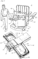
- a typical rider pallet truck 10 includes a power unit 15, a steering control unit 20, and load carrying forks 25.
- the power unit 15 contains a steerable wheel (not shown), usually located directly under the steering control unit, an electric traction motor (not shown), and an electric storage battery 30.
- the power unit 15 also includes a platform 35 onto which an operator 40 may step and ride while controlling the truck 10.
- a rail 42 is provided for the operator to grip while riding on the platform.
- the steering control unit 20 includes a handle 45 mounted at the end of an arm 50 which the operator uses to control steering and other truck functions.
- the handle 45 also contains operator controls, such as twist grips 55 for controlling the direction (forward and reverse), a reversing switch 65, switches 70 and 75 for controlling the raising and lowering the forks 25, and a horn switch 80.
- the load carrying forks 25 extend rearwardly from the power unit 15 and includes small wheels 85 near their rearmost position to aid in supporting a load placed on the forks.
- Outrigger wheels 90 on the power unit are also provided.
- the arm 50 is moved from side to side to control the direction of the truck, and it may be moved either horizontal or vertical to apply the brakes.
- the truck will be reversed should the operator make contact with the switch 65 located at the forward part of the handle 45, as shown in Fig. 2.
- the direction and speed of the truck is controlled by the position of the twist grips 55. These grips are spring biased to a center neutral position. Rotating either grip forward will cause the truck to move forward at a speed proportional to the amount of rotation. Similarly, rotating the grips toward the rear will cause the truck to move in reverse.
- the truck When the operator is walking beside the truck, as shown in Fig. 1, the truck may be moved in the forward direction at a predetermined low speed by operation of a side operated pair of switches 100 and 110. There are two sets of side switches, a pair on each side of the handle 45.
- the handle includes a U-shaped base member 120 including a cross member 125 and a pair of arms 130.
- a mounting member 135 is carried at the center of said base member 120, and a truck electrical control housing 140 is attached thereto, as shown in Fig. 2.
- the pair of rotatable handles 55 extend from the ends of the arms 130 to the control housing 140 for controlling the speed and direction of motion of the truck.
- the mounting member 135 is also connected to the arm 50.
- Switch 100 includes a switch actuator 102 positioned at the end of the arm 130 to be operated by the thumb as the operator grips the arm.
- the actuator 102 is pivoted at 103 with one end exposed for operation by the thumb and the other end positioned to operate the switch element 105.
- Switch 110 includes a second switch actuator 112 positioned away from the end of the arm 130 to be operated by the fingers as the operator grips the arm. Actuator 112 is pivoted at 113 and actuates switch element 115.
- a control circuit responds to the operation of both switches on one side of said handle to cause the truck to move in its forward direction at a predetermined speed.
Landscapes
- Engineering & Computer Science (AREA)
- Chemical & Material Sciences (AREA)
- Combustion & Propulsion (AREA)
- Transportation (AREA)
- Mechanical Engineering (AREA)
- Handcart (AREA)
Description
- This invention relates to a control handle and system for controlling the operation of a materials handling truck, particularly by an operator walking along side the truck, and is also related to a corresponding truck itself.
- A typical rider pallet truck comprises a power unit, a steering control unit and load carrying forks. The power unit contains a steerable wheel, an electric traction motor and an electric storage battery. The power unit also includes a platform onto which the operator may step and ride while controlling the truck. The steering control unit includes a handle which the operator uses to control steering and it also contains operator controls such as twist grips for controlling the direction (forward and reverse) and speed of the truck, a coast control , braking control, controls for raising and lowering the forks, a horn switch and a reversing switch. The load carrying forks extend rearwardly from the power unit and usually have small wheels near the rearmost position to aid in supporting the load.
- When the truck is moved in one increment over long distances, four or more bays (36 feet or more), the operator will usually step up onto the truck and ride. In modern warehouses, an order picking procedure is usually organized in such a way that the operator follows a unidirectional serpentine route through the storage area, picking up stock in a predetermined sequence in order to maximize productivity. Since it is inefficient for the operator to ride the truck when moving only short distances, the operator will usually place the truck in its coast mode and walk along side, picking up the materials from the storage area and placing thos materials on a pallet on the forks.
- Control of the truck's steering while either riding or walking is done by using a conventional steering control handle. Some trucks have been provided with a side control switch placed for use by the operator to control forward motion of the truck.
- In a typical operation, the operator may use the side switch to accelerate the truck to walking speed. When approaching a stopping point, the operator will release the switch and allow the truck to coast while the operator moves to an adjacent rack or shelf to pick up an item and place it on a pallet on the forks. The operator plans the coast of the truck so that the pallet on the forks will stop near the operator's position about the same time the operator is ready to place the item on the pallet. After loading the truck, the operator then again operates the side switch and moves the truck toward the next pick up position.
- The rate of acceleration and speed of the truck may be controlled by jogging the side switch on and off. The coast distance may be controlled by limiting the truck's travel speed prior to releasing the side switch, and of course the time when the side switch is actually released. Generally, the brakes are not needed during this mode of operation although the truck's brakes are of course available for any emergency.
- A materials handling truck of the aforementioned kind is also known from US-A-4,716,980.
- From US-A-5,007,301, which is considered to form the closest prior art in relation to the present invention, there is known a control handle for a walk along materials handling truck comprising a pair of hand grips each one of which being positioned on a respective side of said control handle, wherein each hand grip comprises a first switch actuator positioned on one side of said hand grip so as to be operable by the thumb of an operator walking along side the truck when gripping said hand grip, a second switch actuator positioned on another side of said hand grip so as to be operable by the fingers of an operator walking along side the truck when gripping said hand grip.
- The switch actuator means on the hand grip of US-A-5,007,301 are provided for the simultaneous actuation of the forks of a lift truck upwardly or downwardly and a driving control device, such that the truck may be advanced in either direction while at the same time the forks are lifted or lowered. No means are provided for preventing any inadvertent movement of the truck upon an inadvertent actuation of the corresponding switch.
- The truck according to US-A-4,716,980 is provided with safety means, namely a so called dead man brake, which is actuated by a spring biased platform on which the operator normally stands to release the brake. Switch means are provided in order to bypass the dead man brake for advancing the truck in a coast mode. However, there are no means provided for preventing any inadvertent actuation of such switch.
- In view of the afore mentioned prior art it is the object of the present invention to provide a control handle for a materials handling truck and a corresponding materials handling truck which prevent the truck from being advanced by inadvertently touching or actuating a corresponding switch.
- This object is achieved by a control handle and a corresponding truck having the features of claims 1 and 5, respectively.
- The control handle according to the present invention comprises an improved side switch for use with a materials handling truck, and particularly to a pair of switches that are conveniently placed in a natural position for the operator while walking along side the truck.
- In the present invention, a pair of switches are placed on each side on the steering control handle. A pair of switches is used to prevent inadvertent operation of the truck. One switch of said pair is operated by the thumb while the other is positioned to be operated by the fingers as the operator grasps the handle.
- The steering control unit used in one form of pallet truck includes a handle attached to the outer end of a tiller, the handle itself including a yoke assembly, a central compartment containing severall switches for control of various truck functions, and a pair of twist grips, either one of which may be rotated to control the direction of travel as well as the speed of the truck. The handle may be similar to that described in U.S. patent 3,465,841. Braking of the vehicle is done by positioning the tiller either horizontally or vertically.
- A control circuit responds to the operation of the side switches to move the truck forward at a predetermined speed.
- According to one embodiment of the present invention there is provided a control handle for a walk along materials handling truck comprising a U-shaped control handle base member having a cross member and a pair of arms, first and second switches placed on either side of said handle for permitting the operation of the truck by an operator walking along side, on each side of said handle a first switch actuator positioned at the end of said arm to be operated by the thumb as the operator grips said arm, a second switch actuator positioned away from the end of said arm to be operated by the fingers as the operator grips said arm, and control circuit means responsive to the actuation of both switches on one side of said handle to move the truck in its forward direction up to a predetermined speed.
- The invention further provides a materials handling truck that includes a control handle for permitting the operator to a walk along side the truck and to control the forward travel of movement of the truck, the improvement comprising, means forming a hand grip on each side of the control handle, first and second switches placed on each side of the control handle, a first switch actuator associated with said first switch on each side of the control handle and positioned to be operated by the thumb as the operator grasps said hand grip, a second switch actuator associated with said second switch on each side of the control handle and positioned to be operated by the fingers as the operator grasps said hand grip, and control circuit means responsive to the actuation of both switches on one side of the control handle to move the truck in its forward direction up to a predetermined speed.
- Other objects and advantages of the invention will be apparent from the following description, the accompanying drawings and the appended claims.
-
- Fig. 1 is a perspective view of a rider pallet truck of the type incorporating the present invention;
- Fig. 2 is a perspective view of a control handle incorporating the present invention;
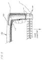
- Fig. 3 is a plan view showing the operator's hand grasping the control handle and operating the two switches that permit auxiliary control of the truck;
- Fig. 4 is a plan view of the control handle with portions broken away to show the position of the auxiliary switches; and
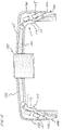
- Fig. 5 is a plan view of the handle with a portion broken away to show the auxiliary switches and switch actuators within the handle.
- Referring now to the drawings which illustrate a preferred embodiment of this invention, and particularly to Fig. 1, a typical
rider pallet truck 10 includes apower unit 15, a steering control unit 20, andload carrying forks 25. Thepower unit 15 contains a steerable wheel (not shown), usually located directly under the steering control unit, an electric traction motor (not shown), and anelectric storage battery 30. Thepower unit 15 also includes aplatform 35 onto which anoperator 40 may step and ride while controlling thetruck 10. Arail 42 is provided for the operator to grip while riding on the platform. - The steering control unit 20 includes a
handle 45 mounted at the end of an arm 50 which the operator uses to control steering and other truck functions. Thehandle 45 also contains operator controls, such astwist grips 55 for controlling the direction (forward and reverse), a reversing switch 65, switches 70 and 75 for controlling the raising and lowering theforks 25, and ahorn switch 80. - The
load carrying forks 25 extend rearwardly from thepower unit 15 and includessmall wheels 85 near their rearmost position to aid in supporting a load placed on the forks.Outrigger wheels 90 on the power unit are also provided. - The arm 50 is moved from side to side to control the direction of the truck, and it may be moved either horizontal or vertical to apply the brakes. The truck will be reversed should the operator make contact with the switch 65 located at the forward part of the
handle 45, as shown in Fig. 2. The direction and speed of the truck is controlled by the position of thetwist grips 55. These grips are spring biased to a center neutral position. Rotating either grip forward will cause the truck to move forward at a speed proportional to the amount of rotation. Similarly, rotating the grips toward the rear will cause the truck to move in reverse. - When the operator is walking beside the truck, as shown in Fig. 1, the truck may be moved in the forward direction at a predetermined low speed by operation of a side operated pair of
switches handle 45. - The handle includes a U-shaped
base member 120 including across member 125 and a pair ofarms 130. Amounting member 135 is carried at the center of saidbase member 120, and a truckelectrical control housing 140 is attached thereto, as shown in Fig. 2. The pair of rotatable handles 55 extend from the ends of thearms 130 to thecontrol housing 140 for controlling the speed and direction of motion of the truck. The mountingmember 135 is also connected to the arm 50. - The first and
second switches handle 45, as shown in more detail in Figs. 4 & 5.Switch 100 includes aswitch actuator 102 positioned at the end of thearm 130 to be operated by the thumb as the operator grips the arm. Theactuator 102 is pivoted at 103 with one end exposed for operation by the thumb and the other end positioned to operate theswitch element 105.Switch 110 includes asecond switch actuator 112 positioned away from the end of thearm 130 to be operated by the fingers as the operator grips the arm.Actuator 112 is pivoted at 113 and actuatesswitch element 115. - While not shown, a control circuit responds to the operation of both switches on one side of said handle to cause the truck to move in its forward direction at a predetermined speed.
- While the form of apparatus herein described constitutes a preferred embodiment of this invention, it is to be understood that the invention is not limited to this precise form of apparatus and that changes may be made therein without departing from the scope of the invention, which is defined in the appended claims.
Claims (5)
- A control handle (45) for a walk along materials handling truck (10) comprising
a pair of hand grips (130) each one of which being positioned on a respective side of said control handle (45),
wherein each hand grip (130) comprises- a first switch actuator (102) positioned on one side of said hand grip so as to be operable by the thumb of an operator walking along side the truck (10) when gripping said hand grip,- a second switch actuator (112) positioned on another side of said hand grip so as to be operable by the fingers of an operator walking along side the truck when gripping said hand grip (130),characterized by- a first switch (100) mounted in each hand grip of said control handle (45) which is operated by a respective said first switch actuator (102) when the operator presses on said first switch actuator (102) with the thumb,- a second switch (110) mounted in each hand grip of said control handle (45) which is operated by a respective said second switch actuator (112) when the operator grips the second switch actuator (112) with one or more fingers and- control circuit means responsive to the simultaneous actuation of both switches (100, 110) of said hand grip (130) to advance the truck at a predetermined speed. - A control handle according to claim 1, characterized by a U-shaped control handle base member having a cross-member (120) and a pair of arms, forming said hand grips (130).
- A control handle according to claim 2, characterized in that said first switch actuator is positioned towards the outside and the end of said hand grip (130) while said second switch actuator is positioned away from the end of the hand grip (130) and on the inside of said hand grip.
- A control handle according to claim 2 or 3, characterized in that the free ends of said hand grip are connected by means of additional hand grips and switching elements provided for the operation of a materials handling truck.
- A materials handling truck that includes a control handle for permitting an operator to walk along side the truck to control the forward travel of movement of the truck, characterized by a control handle according to any of claims 1 to 4.
Applications Claiming Priority (2)
| Application Number | Priority Date | Filing Date | Title |
|---|---|---|---|
| US783567 | 1991-10-25 | ||
| US07/783,567 US5245144A (en) | 1991-10-25 | 1991-10-25 | Walk along hand grip switch control for pallet truck |
Publications (2)
| Publication Number | Publication Date |
|---|---|
| EP0538697A1 EP0538697A1 (en) | 1993-04-28 |
| EP0538697B1 true EP0538697B1 (en) | 1996-03-27 |
Family
ID=25129681
Family Applications (1)
| Application Number | Title | Priority Date | Filing Date |
|---|---|---|---|
| EP92117345A Expired - Lifetime EP0538697B1 (en) | 1991-10-25 | 1992-10-10 | Walk along control for pallet truck |
Country Status (3)
| Country | Link |
|---|---|
| US (1) | US5245144A (en) |
| EP (1) | EP0538697B1 (en) |
| DE (1) | DE69209433T2 (en) |
Families Citing this family (77)
| Publication number | Priority date | Publication date | Assignee | Title |
|---|---|---|---|---|
| DE4408777C2 (en) * | 1994-03-15 | 2002-11-07 | Crown Gabelstapler Gmbh | Drawbar for a hand-guided industrial truck |
| DE4413631C2 (en) * | 1994-04-19 | 1996-02-15 | Wagner Foerdertechnik | Drawbar of a pallet truck |
| US5595259A (en) * | 1995-02-10 | 1997-01-21 | Crown Equipment Corporation | Rotary grip with paddle for use on pallet truck |
| DE19523921C2 (en) * | 1995-06-30 | 2001-11-29 | Jungheinrich Ag | Drawbar for power-driven industrial trucks |
| US5654594A (en) * | 1996-02-27 | 1997-08-05 | Laser Products Ltd. | Ergonomic electrical current switching systems |
| USD408769S (en) | 1996-09-13 | 1999-04-27 | Crown Equipment Corporation | Control position unit for a personnel carrying vehicle |
| US6260646B1 (en) | 1999-04-29 | 2001-07-17 | Raul U. Fernandez | Power-assisted pallet truck |
| US6308792B1 (en) | 1999-05-11 | 2001-10-30 | Michael S. Garrett | Electrical switch for a wagon |
| USD450417S1 (en) | 2000-08-15 | 2001-11-13 | Crown Equipment Corporation | Combination grips and horn buttons for a pallet truck |
| USD445553S1 (en) | 2000-08-15 | 2001-07-24 | Crown Equipment Corporation | Control handle for a pallet truck |
| USD450169S1 (en) | 2000-08-15 | 2001-11-06 | Crown Equipment Corporation | Lift-lower controls for a pallet truck |
| USD445552S1 (en) | 2000-08-15 | 2001-07-24 | Crown Equipment Corporation | Set of thumbwheel drive controls for a pallet truck |
| US6464025B1 (en) | 2001-05-15 | 2002-10-15 | Crown Equipment Corporation | Coast control for walkie/rider pallet truck |
| US6595306B2 (en) * | 2001-08-09 | 2003-07-22 | Crown Equipment Corporation | Supplemental walk along control for walkie/rider pallet trucks |
| ITPD20020205A1 (en) * | 2002-07-26 | 2004-01-26 | Agrinova Di Ceccato Paolo | SIMPLIFIED ELECTRIC MOTORIZATION OF THE ADVANCE OF OPERATING MACHINES OPERATED BY ENDOTHERMAL MOTOR. |
| US20040099453A1 (en) * | 2002-11-26 | 2004-05-27 | Guy Douglas S. | Lift truck with coast mode of operation and indicator |
| US20040226584A1 (en) * | 2003-05-14 | 2004-11-18 | Michael Guest | Multifunctional surface cleaning machine and method of using the same |
| US8302240B2 (en) | 2009-07-29 | 2012-11-06 | Karcher North America, Inc. | Selectively adjustable steering mechanism for use on a floor cleaning machine |
| US7533435B2 (en) | 2003-05-14 | 2009-05-19 | Karcher North America, Inc. | Floor treatment apparatus |
| US20120096671A1 (en) | 2010-10-26 | 2012-04-26 | Karcher North America, Inc. | Floor cleaning apparatus employing a combined sweeper and vaccum assembly |
| US20060064844A1 (en) * | 2003-05-14 | 2006-03-30 | Venard Daniel C | Floating deck for use with a floor cleaning apparatus |
| USD492833S1 (en) | 2003-06-06 | 2004-07-06 | Crown Equipment Corporation | Rider pallet truck |
| US6948739B2 (en) * | 2003-07-22 | 2005-09-27 | Crown Equipment Corporation | Operator support pad for a vehicle |
| US7025157B2 (en) * | 2003-07-25 | 2006-04-11 | The Raymond Corporation | Pallet truck tiller arm with angle detector for speed select |
| DE10338611B3 (en) * | 2003-08-22 | 2005-04-28 | Jungheinrich Ag | follower industrial |
| USD497463S1 (en) | 2003-08-29 | 2004-10-19 | The Raymond Corporation | Control handle for a material handling vehicle |
| USD519706S1 (en) * | 2003-11-06 | 2006-04-25 | The Raymond Corporation | Control handle for a material handling vehicle |
| DE10352695B4 (en) * | 2003-11-12 | 2019-07-18 | Jungheinrich Aktiengesellschaft | Drawbar for power-driven industrial truck |
| US7017689B2 (en) * | 2004-05-06 | 2006-03-28 | Crown Equipment Corporation | Electrical steering assist for material handling vehicles |
| DE102004042226A1 (en) * | 2004-09-01 | 2006-03-02 | Jungheinrich Ag | Tiller for a ride-on and ride-on forklift |
| US7314116B2 (en) * | 2004-10-29 | 2008-01-01 | Jungheinrich Aktiengesellschaft | Walkie/rider truck |
| US7641020B2 (en) * | 2005-04-18 | 2010-01-05 | Jungheinrich Aktiengessellschaft | Hand rail for a walkie/rider truck |
| US7661493B2 (en) | 2005-04-19 | 2010-02-16 | Nmhg Oregon, Llc | Power assisted steering for motorized pallet truck |
| JP2006306190A (en) * | 2005-04-27 | 2006-11-09 | Sanyo Electric Co Ltd | Force input operating device and mobile body having the same |
| CN101626944B (en) * | 2006-02-03 | 2015-04-01 | 克朗设备公司 | material handling vehicle |
| US9645968B2 (en) | 2006-09-14 | 2017-05-09 | Crown Equipment Corporation | Multiple zone sensing for materials handling vehicles |
| AU2007300299C1 (en) * | 2006-09-14 | 2012-11-01 | Crown Equipment Corporation | Systems and methods of remotely controlling a materials handling vehicle |
| US8072309B2 (en) | 2006-09-14 | 2011-12-06 | Crown Equipment Corporation | Systems and methods of remotely controlling a materials handling vehicle |
| US9207673B2 (en) * | 2008-12-04 | 2015-12-08 | Crown Equipment Corporation | Finger-mounted apparatus for remotely controlling a materials handling vehicle |
| US8970363B2 (en) | 2006-09-14 | 2015-03-03 | Crown Equipment Corporation | Wrist/arm/hand mounted device for remotely controlling a materials handling vehicle |
| US9122276B2 (en) | 2006-09-14 | 2015-09-01 | Crown Equipment Corporation | Wearable wireless remote control device for use with a materials handling vehicle |
| US8452464B2 (en) * | 2009-08-18 | 2013-05-28 | Crown Equipment Corporation | Steer correction for a remotely operated materials handling vehicle |
| DE102007049392A1 (en) * | 2007-05-29 | 2008-12-04 | Linde Material Handling Gmbh | fork-lift truck |
| DE102007063224A1 (en) * | 2007-12-31 | 2009-07-02 | Still Sas | Tiller head for an industrial truck |
| DE102008030554A1 (en) | 2008-06-27 | 2009-12-31 | Still Wagner Gmbh | Operator console for a truck |
| US9522817B2 (en) | 2008-12-04 | 2016-12-20 | Crown Equipment Corporation | Sensor configuration for a materials handling vehicle |
| US8731777B2 (en) | 2009-08-18 | 2014-05-20 | Crown Equipment Corporation | Object tracking and steer maneuvers for materials handling vehicles |
| US8577551B2 (en) | 2009-08-18 | 2013-11-05 | Crown Equipment Corporation | Steer control maneuvers for materials handling vehicles |
| US8336654B1 (en) * | 2009-10-15 | 2012-12-25 | Licon Robert C | Power device for pallet trucks |
| JP5916715B2 (en) | 2010-04-29 | 2016-05-11 | ディバーシー・インコーポレーテッド | Floor cleaning tool and method |
| USD654234S1 (en) | 2010-12-08 | 2012-02-14 | Karcher North America, Inc. | Vacuum bag |
| US8978190B2 (en) | 2011-06-28 | 2015-03-17 | Karcher North America, Inc. | Removable pad for interconnection to a high-speed driver system |
| US9205882B1 (en) | 2011-11-17 | 2015-12-08 | Nacco Materials Handling Group, Inc. | Hand grip for industrial vehicles |
| USD718256S1 (en) * | 2012-04-06 | 2014-11-25 | The Raymond Corporation | Switch module |
| USD693529S1 (en) | 2012-09-10 | 2013-11-12 | Karcher North America, Inc. | Floor cleaning device |
| US8875818B2 (en) | 2012-10-15 | 2014-11-04 | Jungheinrich Aktiengesellschaft | Tiller guided industrial truck |
| BR112015022380A2 (en) | 2013-03-14 | 2017-07-18 | Crown Equip Corp | system to provide electrical steering assistance for a material handling vehicle |
| DE102013006721A1 (en) | 2013-04-19 | 2014-10-23 | Jungheinrich Aktiengesellschaft | Tiller-guided industrial truck |
| US9403435B2 (en) | 2014-10-14 | 2016-08-02 | Honda Motor Co., Ltd. | Adjustable ground speed control devices, systems, and methods for walk-behind equipment |
| US9925999B2 (en) | 2015-09-29 | 2018-03-27 | Radio Flyer Inc. | Power assist wagon |
| BR112018015434A2 (en) | 2016-02-09 | 2018-12-18 | Crown Equip Corp | mounting bar assembly mounted on a material handling vehicle, and material handling vehicle. |
| US11167967B2 (en) | 2016-10-31 | 2021-11-09 | Hyster-Yale Group, Inc. | Enhanced traction control for industrial vehicle |
| US10583852B2 (en) | 2016-11-02 | 2020-03-10 | Radio Flyer Inc. | Foldable wagon |
| USD856628S1 (en) | 2017-04-03 | 2019-08-13 | Crown Equipment Corporation | Mounting bar assembly |
| WO2018202301A1 (en) | 2017-05-04 | 2018-11-08 | Alfred Kärcher SE & Co. KG | Floor-cleaning appliance and method for cleaning a floor surface |
| USD866676S1 (en) | 2017-11-02 | 2019-11-12 | Radio Flyer Inc. | Foldable wagon |
| EP3623266B1 (en) * | 2018-09-06 | 2020-11-25 | STILL S.p.A. | Method for operating an industrial truck |
| CN109455218B (en) * | 2018-12-08 | 2024-11-15 | 苏州康多机器人有限公司 | A control armrest device for electric mobile platform |
| USD907868S1 (en) | 2019-01-24 | 2021-01-12 | Karcher North America, Inc. | Floor cleaner |
| DE102019101863A1 (en) * | 2019-01-25 | 2020-07-30 | Jungheinrich Aktiengesellschaft | Control head for an industrial truck |
| CN117767471A (en) | 2019-02-01 | 2024-03-26 | 克朗设备公司 | Onboard charging station for remote control devices |
| US11641121B2 (en) | 2019-02-01 | 2023-05-02 | Crown Equipment Corporation | On-board charging station for a remote control device |
| US10730728B1 (en) * | 2019-04-17 | 2020-08-04 | Zhejiang E-P Equipment Co., Ltd. | Removable plug-in modules for material handling vehicles |
| JP7385398B2 (en) * | 2019-08-08 | 2023-11-22 | 株式会社マキタ | push-wheel transport vehicle |
| KR102844524B1 (en) | 2020-08-11 | 2025-08-12 | 크라운 이큅먼트 코포레이션 | remote control device |
| EP4284748A1 (en) | 2021-01-29 | 2023-12-06 | Crown Equipment Corporation | Work assist system for an industrial vehicle |
| CN215642451U (en) * | 2021-06-25 | 2022-01-25 | 浙江中力机械股份有限公司 | Handle head and carrier with same |
Family Cites Families (14)
| Publication number | Priority date | Publication date | Assignee | Title |
|---|---|---|---|---|
| US1911872A (en) * | 1929-08-01 | 1933-05-30 | Continental Divco Company | Motor delivery vehicle |
| US3190994A (en) * | 1963-10-31 | 1965-06-22 | Shepard Co Lewis | Cam-actuated control switch mounting for motorized lift truck |
| US3465841A (en) * | 1967-10-11 | 1969-09-09 | Crown Controls Corp | Reversible electric motor speed control |
| US3511951A (en) * | 1968-02-12 | 1970-05-12 | Robert G Miller | Hand-held switching device with interlocked trigger actuating means |
| US3557893A (en) * | 1968-02-12 | 1971-01-26 | Webb Co Jervis B | Automatic and manually controlled vehicle |
| GB1313884A (en) * | 1970-05-04 | 1973-04-18 | Lansing Bagnall Ltd | Pedestrian operated industrial trucks |
| US3738441A (en) * | 1972-03-06 | 1973-06-12 | Allis Chalmers | Swivel control handle for lift truck |
| US3834249A (en) * | 1973-03-13 | 1974-09-10 | P Bothwell | Handlebars |
| US4444284A (en) * | 1979-05-18 | 1984-04-24 | Big Joe Manufacturing Company | Control system |
| US4570078A (en) * | 1982-05-27 | 1986-02-11 | Honda Giken Kogyo Kabushiki Kaisha | Switch assembly for a motor vehicle |
| JPS61249881A (en) * | 1985-04-30 | 1986-11-07 | 本田技研工業株式会社 | Mounting structure of switches for vehicles such as motorcycles |
| US4716980A (en) * | 1986-02-14 | 1988-01-05 | The Prime Mover Company | Control system for rider vehicles |
| JP2823199B2 (en) * | 1988-03-10 | 1998-11-11 | ヤマハ発動機株式会社 | Start / stop device for small personal watercraft |
| DE3840800A1 (en) * | 1988-12-01 | 1990-06-07 | Porsche Ag | FLOORING VEHICLE |
-
1991
- 1991-10-25 US US07/783,567 patent/US5245144A/en not_active Expired - Lifetime
-
1992
- 1992-10-10 DE DE69209433T patent/DE69209433T2/en not_active Expired - Lifetime
- 1992-10-10 EP EP92117345A patent/EP0538697B1/en not_active Expired - Lifetime
Also Published As
| Publication number | Publication date |
|---|---|
| DE69209433T2 (en) | 1996-10-10 |
| DE69209433D1 (en) | 1996-05-02 |
| US5245144A (en) | 1993-09-14 |
| EP0538697A1 (en) | 1993-04-28 |
Similar Documents
| Publication | Publication Date | Title |
|---|---|---|
| US5245144A (en) | Walk along hand grip switch control for pallet truck | |
| US3791474A (en) | Motion selector device for a lift truck | |
| US4716980A (en) | Control system for rider vehicles | |
| CA2476070C (en) | Material handling vehicle with ergonomic dual control handle system | |
| US4287966A (en) | Industrial truck | |
| US6883625B2 (en) | Supplemental jog and/or twist grip or other drive motor speed walk along controllers for walkie/rider pallet trucks | |
| US5044472A (en) | Dual operator position for material handling vehicle | |
| US6464025B1 (en) | Coast control for walkie/rider pallet truck | |
| US5011363A (en) | Extend and retract control for fork lifts | |
| CA2210037A1 (en) | Motion control system for a materials handling vehicle | |
| EP1505034B1 (en) | Control system for material handling vehicle with dual control handles | |
| CA2158375A1 (en) | Multifunction single lever control for lift trucks | |
| US3134063A (en) | Plural battery and plural motor control system for industrial truck | |
| US6793247B2 (en) | Order picker angled steering wheel | |
| JPH11171038A (en) | Conveying device | |
| US3098543A (en) | Multi-purpose control means for industrial trucks and the like | |
| US7051832B2 (en) | Material handling vehicle with dual control handles | |
| CN223672437U (en) | Material handling cart, handles used on its sides, and devices for use on the material handling cart from its lateral side, adjacent to and outside its side. | |
| JP3359022B2 (en) | Cargo handling vehicle | |
| JP2002249300A (en) | Forward/backward switching device for forklift | |
| JP2003020198A (en) | Cargo handling vehicle | |
| HK40073185A (en) | Operation panel for aerial work vehicles | |
| JP2003048700A (en) | Assist grip for lever operating device of order picker | |
| JPH11255085A (en) | Brake device for lift truck | |
| JP2003020200A (en) | Cargo handling vehicle |
Legal Events
| Date | Code | Title | Description |
|---|---|---|---|
| PUAI | Public reference made under article 153(3) epc to a published international application that has entered the european phase |
Free format text: ORIGINAL CODE: 0009012 |
|
| AK | Designated contracting states |
Kind code of ref document: A1 Designated state(s): DE FR GB |
|
| 17P | Request for examination filed |
Effective date: 19930517 |
|
| 17Q | First examination report despatched |
Effective date: 19930927 |
|
| GRAH | Despatch of communication of intention to grant a patent |
Free format text: ORIGINAL CODE: EPIDOS IGRA |
|
| GRAA | (expected) grant |
Free format text: ORIGINAL CODE: 0009210 |
|
| AK | Designated contracting states |
Kind code of ref document: B1 Designated state(s): DE FR GB |
|
| REF | Corresponds to: |
Ref document number: 69209433 Country of ref document: DE Date of ref document: 19960502 |
|
| ET | Fr: translation filed | ||
| PLBE | No opposition filed within time limit |
Free format text: ORIGINAL CODE: 0009261 |
|
| 26N | No opposition filed | ||
| REG | Reference to a national code |
Ref country code: FR Ref legal event code: ST |
|
| REG | Reference to a national code |
Ref country code: FR Ref legal event code: RN |
|
| REG | Reference to a national code |
Ref country code: FR Ref legal event code: FC |
|
| REG | Reference to a national code |
Ref country code: GB Ref legal event code: IF02 |
|
| PGFP | Annual fee paid to national office [announced via postgrant information from national office to epo] |
Ref country code: DE Payment date: 20101022 Year of fee payment: 19 |
|
| PGFP | Annual fee paid to national office [announced via postgrant information from national office to epo] |
Ref country code: GB Payment date: 20101021 Year of fee payment: 19 |
|
| PGFP | Annual fee paid to national office [announced via postgrant information from national office to epo] |
Ref country code: FR Payment date: 20111103 Year of fee payment: 20 |
|
| REG | Reference to a national code |
Ref country code: DE Ref legal event code: R071 Ref document number: 69209433 Country of ref document: DE |
|
| REG | Reference to a national code |
Ref country code: DE Ref legal event code: R071 Ref document number: 69209433 Country of ref document: DE |
|
| REG | Reference to a national code |
Ref country code: GB Ref legal event code: PE20 Expiry date: 20121009 |
|
| PG25 | Lapsed in a contracting state [announced via postgrant information from national office to epo] |
Ref country code: GB Free format text: LAPSE BECAUSE OF EXPIRATION OF PROTECTION Effective date: 20121009 |
|
| P01 | Opt-out of the competence of the unified patent court (upc) registered |
Effective date: 20230529 |