EP0536774A1 - An electromagnetically actuated fuel atomising and metering valve of very small dimensions - Google Patents
An electromagnetically actuated fuel atomising and metering valve of very small dimensions Download PDFInfo
- Publication number
- EP0536774A1 EP0536774A1 EP92117296A EP92117296A EP0536774A1 EP 0536774 A1 EP0536774 A1 EP 0536774A1 EP 92117296 A EP92117296 A EP 92117296A EP 92117296 A EP92117296 A EP 92117296A EP 0536774 A1 EP0536774 A1 EP 0536774A1
- Authority
- EP
- European Patent Office
- Prior art keywords
- wall
- core
- valve according
- annular
- disc
- Prior art date
- Legal status (The legal status is an assumption and is not a legal conclusion. Google has not performed a legal analysis and makes no representation as to the accuracy of the status listed.)
- Withdrawn
Links
Images


Classifications
-
- F—MECHANICAL ENGINEERING; LIGHTING; HEATING; WEAPONS; BLASTING
- F02—COMBUSTION ENGINES; HOT-GAS OR COMBUSTION-PRODUCT ENGINE PLANTS
- F02M—SUPPLYING COMBUSTION ENGINES IN GENERAL WITH COMBUSTIBLE MIXTURES OR CONSTITUENTS THEREOF
- F02M51/00—Fuel-injection apparatus characterised by being operated electrically
- F02M51/06—Injectors peculiar thereto with means directly operating the valve needle
- F02M51/061—Injectors peculiar thereto with means directly operating the valve needle using electromagnetic operating means
- F02M51/0625—Injectors peculiar thereto with means directly operating the valve needle using electromagnetic operating means characterised by arrangement of mobile armatures
- F02M51/0664—Injectors peculiar thereto with means directly operating the valve needle using electromagnetic operating means characterised by arrangement of mobile armatures having a cylindrically or partly cylindrically shaped armature, e.g. entering the winding; having a plate-shaped or undulated armature entering the winding
- F02M51/0667—Injectors peculiar thereto with means directly operating the valve needle using electromagnetic operating means characterised by arrangement of mobile armatures having a cylindrically or partly cylindrically shaped armature, e.g. entering the winding; having a plate-shaped or undulated armature entering the winding the armature acting as a valve or having a short valve body attached thereto
-
- F—MECHANICAL ENGINEERING; LIGHTING; HEATING; WEAPONS; BLASTING
- F02—COMBUSTION ENGINES; HOT-GAS OR COMBUSTION-PRODUCT ENGINE PLANTS
- F02M—SUPPLYING COMBUSTION ENGINES IN GENERAL WITH COMBUSTIBLE MIXTURES OR CONSTITUENTS THEREOF
- F02M51/00—Fuel-injection apparatus characterised by being operated electrically
- F02M51/06—Injectors peculiar thereto with means directly operating the valve needle
- F02M51/061—Injectors peculiar thereto with means directly operating the valve needle using electromagnetic operating means
- F02M51/0614—Injectors peculiar thereto with means directly operating the valve needle using electromagnetic operating means characterised by arrangement of electromagnets or fixed armature
-
- F—MECHANICAL ENGINEERING; LIGHTING; HEATING; WEAPONS; BLASTING
- F02—COMBUSTION ENGINES; HOT-GAS OR COMBUSTION-PRODUCT ENGINE PLANTS
- F02M—SUPPLYING COMBUSTION ENGINES IN GENERAL WITH COMBUSTIBLE MIXTURES OR CONSTITUENTS THEREOF
- F02M61/00—Fuel-injectors not provided for in groups F02M39/00 - F02M57/00 or F02M67/00
- F02M61/16—Details not provided for in, or of interest apart from, the apparatus of groups F02M61/02 - F02M61/14
- F02M61/168—Assembling; Disassembling; Manufacturing; Adjusting
Definitions
- the present invention relates to an electromagnetically actuated fuel atomising and metering valve for a fuel supply device of a motor vehicle internal combustion engine.
- This type of valve substantially comprises a body within which are housed an annular electromagnet, a tubular core disposed within the electromagnet and a shutter member movable between a closure position in which it closes at least once fuel injection orifice and an open position in which the passage through this orifice is left open.
- the shutter member is fixed to a tubular armature which can be attracted by the core when the electromagnet is excited.
- the object of the present invention is that of providing an electromagnetically actuated fuel atomising and metering valve with which these disadvantages can be eliminated and therefore which will be of very small size and very simple structure so as to be produced at low cost.
- an electromagnetically actuated fuel atomising and metering valve for a fuel supply device of an internal combustion engine comprising substantially a body within which are housed an annular electromagnet, a tubular core disposed within the electromagnet, and a shutter member movable from a closure position in which it closes at least one injection orifice to an open position in which it leaves the passage through this orifice open, the said shutter member being fixed to a tubular armature which can be attracted by the said core, characterised in that the said body includes:
- the valve of the invention substantially comprises a body generally indicated 1 within which are housed an annular electromagnet 2, a tubular core 3 disposed within the electromagnet, and a shutter member 4 which is movable from a closure position, shown in figure 1, in which it closes at least one fuel injection orifice 5, to an open position in which it leaves the passage through this orifice open.
- the shutter member is fixed to an armature 6, also of tubular form, which can be attracted by the core 3.
- the body 1 substantially comprises 2 ferromagnet element 7 which is provided with a substantially flat lower wall 8 in which the injection orifice 5 is formed, an annular first wall 9 adapted to house the shutter member 4 and at least partially receive the armature 6 and a second annular wall 10 coaxial with the first and adapted to house the lower end 11 of the core 3.
- the annular wall 10 is also adapted to house a sealing ring 13 which is interposed between the core 3 and the inner surface of the wall itself, as well as a spacer washer 14.
- the body 1 further includes a tubular casing 15 made of sheet metal and adapted to contain the electromagnet 2 and the core 3; this casing is made from a sheet metal blank having a substantially rectangular form as is shown in Figure 3; this blank is conveniently provided with a pair of projections 17 which can be fitted into corresponding recesses 18, after folding of the blank.
- the lower end of the casing 15 overlies at least part of the side wall 10 of the ferromagnet element 7 and is fixed to this by laser welding 19.
- the core 3 has a flange 20 which is fitted into the upper end of the casing 15 and is fixed to this by means of a further laser welding, indicated 21.
- the shutter member 4 and the armature 6 as is clearly seen from Figure 1 are integrally formed from a cup shape body which is provided with a flat bottom wall 23 and a tubular side wall 24; in the cup shape body thus obtained there is formed at least one hole 25 for the fuel. Conveniently these holes are disposed in the annular intersection region between the flat wall 23 and the tubular wall 24 and the axis of each is slightly inclined with respect to the axis of the armature; the said holes open into an annular groove 26 formed within the armature.
- the holes 25 are formed in the tubular wall 24 and the axis of each of these is substantially radial.
- the flat bottom wall 8 of the ferromagnet element 7 is formed by a disc (indicated with the same reference numeral), the upper surface 27 of which is coupled to a corresponding flat end surface of the lateral wall 9 of the ferromagnet element 7; this disc is fixed to the wall 9 by means of a third laser welding, indicated 28 which is therefore located in the plane of contact between the lower surface of the wall 23 and the upper surface of the disc itself.
- the lateral wall 9 of the ferromagnet element 7 has an annular projection 29 ( Figure 2) which overlies the upper surface 27 of the disk 8 and the thickness of which decreases in the direction of the radius of the disc itself as is clearly seen in Figure 2; the welding 28 is formed between the annular projection 29 and the disc.
- the minimum thickness (indicated 's' in Figure 2) of the annular projection 29 must lie between 0.2 and 0.4mm.
- the valve further includes a coil spring 30 which is fitted in the interior of the armature 6 and is adapted to contact on the bottom wall 23 of the shutter member; furthermore a tube 31 is mounted, by plastic deformation of the zone 30a, within the interior of the core 3 and is operable to apply a preload to the spring to hold the shutter member against the disc 8.
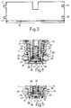
- the disc 8 can be shaped differently from that shown in Figure 1 may include for example, an annular projection 32 (Figure 6), which projects from the lower surface of the disc itself. This projection is delimited by an internal conical surface 33 against which fuel exiting from the injection orifice 5 can be directed for the purpose of improving the atomization thereof.
- the welding 28 which fixes this disc to the ferromagnet element 7 can be formed within an annular groove 36 ( Figure 4) on the lower surface of the disc itself, whilst the ferromagnet element 7 is not provided with the annular projection 29 and is formed integrally of pressed sheet metal with the casing 15.
- annular groove 37 formed on the upper surface of the disc 8 receives the terminal edge of the ferromagnet element 7.
- the ferromagnet element 7 and the disc 8 may be formed integrally.
- a sleeve 40 (Figure 1) within the interior of which is formed a fuel duct 41 within which is disposed a filter 42.
- a cap 43 Over this sleeve, the flange 20 and the casing 15 is disposed a cap 43 in which are fitted electrical connection elements 44 connected to the conductors of the electromagnet 2.
- a pair of sealing rings 45 and 46 is provided to form a seal respectively between the valve and the fuel duct (not shown), which supplies the fuel thereto, and between the valve and the seat in which this is mounted.
- the operation of the valve is as follows: Fuel is supplied to the interior of the duct 41 and through the tube 31 reaches the interior of the armature 6; from here the fuel flows towards the injection orifice 5 through the holes 25 in the shutter member 4 as soon as the electromagnet 2 is excited; in this way the armature 6 is attracted by the core 3 overcoming the resistance of the coil spring 30.
- the fuel which enters into the valve cannot flow towards the electromagnet 2 and therefore to the interior of the casing 15, due to the presence of the sealing ring 13 which applies pressure both to the outer surface of the core 3 and the inner surface of the wall 10 of the ferromagnet element 7.
- valve of the invention The dimensions of the valve of the invention are very small; in fact the electromagnet 2 is contained within the casing 15 which, being made of sheet metal is very thin. Moreover the magnetic circuit is formed within the core 3, the armature 6 and the wall 10 of the ferro magnet element 7 which, because of its structure and the manner of connection to the casing 15, has extremely small dimensions (in particular the outer diameter).
- the seal formed with the valve is very good since the upper surface 27 of the disc 8 and the lower surface of the wall 9 against which the first surface engages can be ground in a very precise manner before the welding 28 is effected; consequently, therefore, the surface 27 of the said disc is perfectly perpendicular to the axis of the ferromagnet element 7 and therefore to the shutter member 5.
- the structure of the valve of the invention is very simple and it can be made at low cost; in fact, above all, the casing 15 can be made from a metal blank such as that shown in Figure 3 by means of simple cutting and folding operations; similarly the ferromagnet element 7, the core 3 and the armature 6 (which constitutes a single piece with the shutter member 5) can be made in a simple and rapid manner by means of automatic machines. Finally, the connection between the disc 8 and the ferromagnet element 7, between this and the casing 15, and between this latter and the flange 20 of the core 3 are formed by means of three simple welds (28, 19, and 21) which can also be performed on automatic machines.
Landscapes
- Engineering & Computer Science (AREA)
- Physics & Mathematics (AREA)
- Electromagnetism (AREA)
- Chemical & Material Sciences (AREA)
- Combustion & Propulsion (AREA)
- Mechanical Engineering (AREA)
- General Engineering & Computer Science (AREA)
- Manufacturing & Machinery (AREA)
- Fuel-Injection Apparatus (AREA)
Abstract
The valve substantially comprises a ferromagnet element (7) provided with a flat bottom wall (8) in which is formed an injection orifice (5), a first annular wall (9), adapted to house a movable shutter member (4) and at least partially house an armature (6) fixed to the member itself, and a second annular wall (10) coaxial with the first and adapted to house the lower end (11) of a core (3) and a sealing ring (13) interposed between the wall and the core; the valve further includes a tubular casing (15) of sheet metal adapted to contain an electromagnet (2) and the core (3), and the lower end of the casing overlying at least a part of the wall (10) of the ferromagnet element and being fixed to this by means of laser welding (19).
Description
- The present invention relates to an electromagnetically actuated fuel atomising and metering valve for a fuel supply device of a motor vehicle internal combustion engine.
- This type of valve substantially comprises a body within which are housed an annular electromagnet, a tubular core disposed within the electromagnet and a shutter member movable between a closure position in which it closes at least once fuel injection orifice and an open position in which the passage through this orifice is left open. The shutter member is fixed to a tubular armature which can be attracted by the core when the electromagnet is excited.
- Known valves of the type briefly described have been of a rather large size and are constructionally rather complex, and therefore expensive, both because of the shape of the various parts and members of which they are made and because of the manner in which these parts are connected together.
- The object of the present invention is that of providing an electromagnetically actuated fuel atomising and metering valve with which these disadvantages can be eliminated and therefore which will be of very small size and very simple structure so as to be produced at low cost.
- These objects are achieved by means of an electromagnetically actuated fuel atomising and metering valve for a fuel supply device of an internal combustion engine comprising substantially a body within which are housed an annular electromagnet, a tubular core disposed within the electromagnet, and a shutter member movable from a closure position in which it closes at least one injection orifice to an open position in which it leaves the passage through this orifice open, the said shutter member being fixed to a tubular armature which can be attracted by the said core, characterised in that the said body includes:
- a ferromagnetic element provided with a flat bottom wall in which the said injection orifice is formed, a first annular wall adapted to house the said shutter member and at least partially house the said armature, and a second annular wall coaxial with the first and adapted to house the lower end of the said core and a sealing ring interposed between the said second annual wall and the said core;
- a tubular sheet metal casing adapted to contain the said electromagnet and the said core and made by folding a sheet metal blank having a substantially rectangular form; and
- the lower end of the said casing overlying at least a part of the said second annular wall of the said ferromagnetic element and being fixed to this by means of a first laser welding.
- For a better understanding of the structure and manner of operation of the valve of the invention a description of a particular embodiment will now be given, by way of example with reference to the attached drawings, in which:
- Figure 1 is an axial section of the valve of the invention;
- Figure 2 is an enlarged detail of Figure 1;
- Figure 3 is a side view of a blank from which the casing of the valve is made; and
- Figures from 4 to 8 show axial sections of the lower part of the valve formed according to different embodiments thereof.
- The valve of the invention substantially comprises a body generally indicated 1 within which are housed an
annular electromagnet 2, atubular core 3 disposed within the electromagnet, and ashutter member 4 which is movable from a closure position, shown in figure 1, in which it closes at least onefuel injection orifice 5, to an open position in which it leaves the passage through this orifice open. The shutter member is fixed to anarmature 6, also of tubular form, which can be attracted by thecore 3. - According to the invention the body 1 substantially comprises 2
ferromagnet element 7 which is provided with a substantially flatlower wall 8 in which theinjection orifice 5 is formed, an annularfirst wall 9 adapted to house theshutter member 4 and at least partially receive thearmature 6 and a secondannular wall 10 coaxial with the first and adapted to house thelower end 11 of thecore 3. Theannular wall 10 is also adapted to house asealing ring 13 which is interposed between thecore 3 and the inner surface of the wall itself, as well as aspacer washer 14. - The body 1 further includes a
tubular casing 15 made of sheet metal and adapted to contain theelectromagnet 2 and thecore 3; this casing is made from a sheet metal blank having a substantially rectangular form as is shown in Figure 3; this blank is conveniently provided with a pair of projections 17 which can be fitted intocorresponding recesses 18, after folding of the blank. - As is clearly seen in Figure 1, the lower end of the
casing 15 overlies at least part of theside wall 10 of theferromagnet element 7 and is fixed to this by laser welding 19. - The
core 3 has aflange 20 which is fitted into the upper end of thecasing 15 and is fixed to this by means of a further laser welding, indicated 21. Theshutter member 4 and thearmature 6 as is clearly seen from Figure 1 are integrally formed from a cup shape body which is provided with aflat bottom wall 23 and atubular side wall 24; in the cup shape body thus obtained there is formed at least onehole 25 for the fuel. Conveniently these holes are disposed in the annular intersection region between theflat wall 23 and thetubular wall 24 and the axis of each is slightly inclined with respect to the axis of the armature; the said holes open into anannular groove 26 formed within the armature. - In the embodiment shown in Figure 7 the
holes 25 are formed in thetubular wall 24 and the axis of each of these is substantially radial. - In the embodiment of Figure 1 the
flat bottom wall 8 of theferromagnet element 7 is formed by a disc (indicated with the same reference numeral), theupper surface 27 of which is coupled to a corresponding flat end surface of thelateral wall 9 of theferromagnet element 7; this disc is fixed to thewall 9 by means of a third laser welding, indicated 28 which is therefore located in the plane of contact between the lower surface of thewall 23 and the upper surface of the disc itself. Conveniently thelateral wall 9 of theferromagnet element 7 has an annular projection 29 (Figure 2) which overlies theupper surface 27 of thedisk 8 and the thickness of which decreases in the direction of the radius of the disc itself as is clearly seen in Figure 2; thewelding 28 is formed between theannular projection 29 and the disc. Moreover it has been found that in order to obtain awelding 28 with good characteristics, the minimum thickness (indicated 's' in Figure 2) of theannular projection 29 must lie between 0.2 and 0.4mm. Furthermore the axis of the tool used to form thewelding 28 conveniently forms an angle α = 20 with the axis of the valve; the line representing this axis has been indicated 'd' in Figure 1. - The valve further includes a
coil spring 30 which is fitted in the interior of thearmature 6 and is adapted to contact on thebottom wall 23 of the shutter member; furthermore atube 31 is mounted, by plastic deformation of thezone 30a, within the interior of thecore 3 and is operable to apply a preload to the spring to hold the shutter member against thedisc 8. - The
disc 8 can be shaped differently from that shown in Figure 1 may include for example, an annular projection 32 (Figure 6), which projects from the lower surface of the disc itself. This projection is delimited by an internalconical surface 33 against which fuel exiting from theinjection orifice 5 can be directed for the purpose of improving the atomization thereof. - The
welding 28 which fixes this disc to theferromagnet element 7 can be formed within an annular groove 36 (Figure 4) on the lower surface of the disc itself, whilst theferromagnet element 7 is not provided with theannular projection 29 and is formed integrally of pressed sheet metal with thecasing 15. - In the embodiment of Figure 5 an
annular groove 37 formed on the upper surface of thedisc 8 receives the terminal edge of theferromagnet element 7. - Finally, as in the embodiment of Figures 7 and 8, the
ferromagnet element 7 and thedisc 8 may be formed integrally. - In the embodiment of Figures 1, 4, 5, and 6 there are formed 2 coaxial
annular grooves 38, concentric with the axis of the valve on theupper surface 27 of thedisc 8; these give rise to two corresponding projections on which theshutter member 4 engages. In the embodiment of Figures 7 and 8 the annular grooves, and therefore the corresponding projections, are on the other hand formed on thebottom wall 23 of theshutter member 5. - Upwardly from the
flange 20 projects a sleeve 40 (Figure 1) within the interior of which is formed afuel duct 41 within which is disposed afilter 42. Over this sleeve, theflange 20 and thecasing 15 is disposed a cap 43 in which are fittedelectrical connection elements 44 connected to the conductors of theelectromagnet 2. - Finally, a pair of
sealing rings - The operation of the valve is as follows: Fuel is supplied to the interior of the
duct 41 and through thetube 31 reaches the interior of thearmature 6; from here the fuel flows towards theinjection orifice 5 through theholes 25 in theshutter member 4 as soon as theelectromagnet 2 is excited; in this way thearmature 6 is attracted by thecore 3 overcoming the resistance of thecoil spring 30. - The fuel which enters into the valve cannot flow towards the
electromagnet 2 and therefore to the interior of thecasing 15, due to the presence of thesealing ring 13 which applies pressure both to the outer surface of thecore 3 and the inner surface of thewall 10 of theferromagnet element 7. - The dimensions of the valve of the invention are very small; in fact the
electromagnet 2 is contained within thecasing 15 which, being made of sheet metal is very thin. Moreover the magnetic circuit is formed within thecore 3, thearmature 6 and thewall 10 of theferro magnet element 7 which, because of its structure and the manner of connection to thecasing 15, has extremely small dimensions (in particular the outer diameter). - The seal formed with the valve is very good since the
upper surface 27 of thedisc 8 and the lower surface of thewall 9 against which the first surface engages can be ground in a very precise manner before thewelding 28 is effected; consequently, therefore, thesurface 27 of the said disc is perfectly perpendicular to the axis of theferromagnet element 7 and therefore to theshutter member 5. - The structure of the valve of the invention is very simple and it can be made at low cost; in fact, above all, the
casing 15 can be made from a metal blank such as that shown in Figure 3 by means of simple cutting and folding operations; similarly theferromagnet element 7, thecore 3 and the armature 6 (which constitutes a single piece with the shutter member 5) can be made in a simple and rapid manner by means of automatic machines. Finally, the connection between thedisc 8 and theferromagnet element 7, between this and thecasing 15, and between this latter and theflange 20 of thecore 3 are formed by means of three simple welds (28, 19, and 21) which can also be performed on automatic machines. - The embodiments of the present invention described herein can have modifications and variations introduced thereto without departing from the invention itself.
Claims (12)
- An electromagnetically actuated fuel atomising and metering valve for a fuel supply device of an internal combustion engine substantially comprising a body (1) within which is housed an annular electromagnet (2), a tubular core (3) disposed within the electromagnet and a shutter member (4) movable from a closure position in which it closes at least one fuel injection orifice (5) to an open position in which it leaves the passage through this orifice open, the said shutter member (4) being fixed to a tubular armature (6) which can be attracted by the said core (3), characterised in that the said body (1) includes:
a ferromagnetic element (7) provided with a flat bottom wall (8) in which the said injection orifice is formed, a first annular wall (9) adapted to house the said shutter member (4) and at least partially house the said armature (6), and a second annular wall (10) coaxial with the first and adapted to house the lower end (11) of the said core (3) and a sealing ring (13) interposed between the said second annular wall (10) and the said core;
a tubular casing (15) of sheet metal adapted to contain the said electromagnet (2) and the said core (3) and made by folding a sheet metal blank (16) having a substantially rectangular form; and
the lower end of the said casing (15) overlying at least a part of the second annular wall (10) of the said ferromagnet elements (7) and being fixed to this by means of a first laser welding (19). - A valve according to claim 1, characterised in that the said core (3) has a flange (20) which is fitted into the upper end of the said casing (15) and which is fixed to this by means of a second laser welding (21).
- A valve according to claim 1 or claim 2, characterised in that the said actuator member (5) and the said armature (6) are formed integrally in the form of a cup which is provided with a flat bottom wall (23) and a tubular side wall (24) and in which there is formed at least one hole (25) for the fuel, which hole passes through one of the said walls.
- A valve according to claim 3, characterised in that the said holes (25) are formed in the annular intersection region between the said flat wall (23) and the said tubular wall (24), the axis of each of the said holes being slightly inclined with respect to the axis of the armature (6).
- A valve according to any of claims from 1 to 3, characterised in that the said holes (25) are formed in the said tubular wall (24) and the axis of each of these is radial.
- A valve according to any preceding claim, characterised in that the said flat bottom wall (8) of the said ferromagnetic element is formed by a circular disc (8) having a flat upper surface (27) coupled to a corresponding flat surface of the said side wall (9) of the ferromagnetic element, the said disc (8) being fixed to the said first side wall (9) by a third laser welding (28).
- A valve according to claim 6, characterised in that the said first side wall (9) of the ferromagnetic element (7) has an annular projection (29) which overlies the said upper surface (27) of the said plate (8) and the thickness of which decreases in the direction of the radius of the disc, the said third laser welding (28) being effected between the said annular projection and the said disc.
- A valve according to claim 7, characterised in that the minimum thickness of the said annular projection (29) lies between 0.2 and 0.4mm.
- A valve according to any of claims from 3 to 9, characterised in that it includes a coil spring (30) fitted in the said armature (6) and operable to engage on the said bottom wall (23) of the said cup shape body, within the said core (3) there being mounted, by plastic deformation, a tube (31) operable to apply a pre-load to the said spring.
- A valve according to any of the claims from 6 to 8, characterised in that the said disc (8) has a tubular projection (32), projecting from the lower surface of the disc itself.
- A valve according to any preceding claim, characterised in that the said third laser welding (28) is located substantially in the same plane as that in which the lower surface of the lower wall (23) of the shutter member (4) engages on the upper surface of the said disc (8).
- A valve according to any preceding claim, characterised in that the said ferromagnetic element (7) and the said casing (15) are made integrally of pressed sheet metal.
Applications Claiming Priority (2)
| Application Number | Priority Date | Filing Date | Title |
|---|---|---|---|
| ITTO910772 | 1991-10-11 | ||
| ITTO910772A IT1250846B (en) | 1991-10-11 | 1991-10-11 | ELECTROMAGNETIC-OPERATED FUEL DOSING AND PULVERIZING VALVE WITH VERY LOW DIMENSIONS |
Publications (1)
| Publication Number | Publication Date |
|---|---|
| EP0536774A1 true EP0536774A1 (en) | 1993-04-14 |
Family
ID=11409638
Family Applications (1)
| Application Number | Title | Priority Date | Filing Date |
|---|---|---|---|
| EP92117296A Withdrawn EP0536774A1 (en) | 1991-10-11 | 1992-10-09 | An electromagnetically actuated fuel atomising and metering valve of very small dimensions |
Country Status (3)
| Country | Link |
|---|---|
| US (1) | US5263649A (en) |
| EP (1) | EP0536774A1 (en) |
| IT (1) | IT1250846B (en) |
Cited By (8)
| Publication number | Priority date | Publication date | Assignee | Title |
|---|---|---|---|---|
| EP0649983A1 (en) * | 1993-10-26 | 1995-04-26 | MAGNETI MARELLI S.p.A. | An electromagnetically operated fuel metering and atomising valve |
| EP0582298B1 (en) * | 1992-08-07 | 1996-05-08 | MAGNETI MARELLI S.p.A. | Perfected electromagnetic fuel metering and atomizing valve |
| US5692723A (en) * | 1995-06-06 | 1997-12-02 | Sagem-Lucas, Inc. | Electromagnetically actuated disc-type valve |
| US5979866A (en) * | 1995-06-06 | 1999-11-09 | Sagem, Inc. | Electromagnetically actuated disc-type valve |
| DE19730344C2 (en) * | 1996-07-31 | 2000-05-11 | Mitsubishi Electric Corp | Cylinder fuel injector |
| WO2002086309A1 (en) * | 2001-04-24 | 2002-10-31 | Crt Common Rail Technologies Ag | Fuel-injection valve for internal combustion engines |
| WO2003016707A1 (en) * | 2001-08-08 | 2003-02-27 | Siemens Aktiengesellschaft | Dosing device |
| EP2557343A2 (en) | 2011-08-09 | 2013-02-13 | Pierburg GmbH | Electromagnetic valve |
Families Citing this family (10)
| Publication number | Priority date | Publication date | Assignee | Title |
|---|---|---|---|---|
| IT1256933B (en) * | 1992-08-07 | 1995-12-27 | Weber Srl | ELECTROMAGNETICALLY OPERATED FUEL DOSING AND PULVERIZING VALVE. |
| US5335863A (en) * | 1993-05-03 | 1994-08-09 | Siemens Automotive L.P. | Filter cartridge mounting for a top-feed fuel injector |
| US5433386A (en) * | 1994-06-24 | 1995-07-18 | Siemens Automotive L.P. | Fuel injector having an adjustment tube that discourages support for a vapor bubble dome |
| EP0745764B1 (en) * | 1995-06-02 | 2001-03-21 | Ganser-Hydromag Ag | Fuel injection valve for internal combustion engines |
| US5738284A (en) * | 1995-06-06 | 1998-04-14 | Siemens Automotive Corporation | Inverted coil |
| JP2824761B2 (en) * | 1996-06-07 | 1998-11-18 | 株式会社ケーヒン | Filter in fuel injection valve |
| US5921475A (en) * | 1997-08-07 | 1999-07-13 | Ford Motor Company | Automotive fuel injector |
| JP3941269B2 (en) * | 1997-12-11 | 2007-07-04 | 株式会社デンソー | Laser welding structure and method of metal member, and fuel injection valve |
| US6666190B1 (en) | 2003-01-03 | 2003-12-23 | Ford Global Technologies, Llc | Integrated fuel delivery and electrical connection for electronic fuel injectors |
| US20090224079A1 (en) * | 2008-03-04 | 2009-09-10 | Caterpillar Inc. | Fuel injector, valve body remanufacturing process and machine component manufacturing method |
Citations (5)
| Publication number | Priority date | Publication date | Assignee | Title |
|---|---|---|---|---|
| DE3105652A1 (en) * | 1981-02-17 | 1982-09-16 | Eks Elektromagnetik Dr. Scheuerer Kg, 7143 Vaihingen | Valve magnet for direct current |
| EP0200865A1 (en) * | 1985-05-07 | 1986-11-12 | VDO Adolf Schindling AG | Injection valve |
| WO1991011605A2 (en) * | 1990-02-03 | 1991-08-08 | Robert Bosch Gmbh | Electromagnetically operated valve |
| WO1991019090A1 (en) * | 1990-06-07 | 1991-12-12 | Robert Bosch Gmbh | Electromagnetically operated fuel-injection valve |
| DE4023828A1 (en) * | 1990-07-27 | 1992-01-30 | Bosch Gmbh Robert | Adjusting EM valve for fuel injection - adjusting current without requiring access to return spring by changing magnetic characteristics of inner pole |
Family Cites Families (6)
| Publication number | Priority date | Publication date | Assignee | Title |
|---|---|---|---|---|
| IT1122430B (en) * | 1979-08-03 | 1986-04-23 | Alfa Romeo Spa | QUICK TRANSITOR ELECTROINJECTOR |
| IT1152503B (en) * | 1982-08-18 | 1987-01-07 | Alfa Romeo Spa | ELECTROINJECTOR FOR A C.I. ENGINE |
| GB8328510D0 (en) * | 1983-10-25 | 1983-11-23 | Lucas Ind Plc | Gasoline injector |
| IT1183213B (en) * | 1985-02-07 | 1987-10-15 | Alfa Romeo Spa | ELECTRIMAGNETIC INJECTOR FOR A C.I. |
| DE8709111U1 (en) * | 1987-07-01 | 1987-09-17 | Siemens Ag, 1000 Berlin Und 8000 Muenchen, De | |
| US5100102A (en) * | 1990-10-15 | 1992-03-31 | Ford Motor Company | Compact electronic fuel injector |
-
1991
- 1991-10-11 IT ITTO910772A patent/IT1250846B/en active IP Right Grant
-
1992
- 1992-10-09 EP EP92117296A patent/EP0536774A1/en not_active Withdrawn
- 1992-10-13 US US07/959,715 patent/US5263649A/en not_active Expired - Lifetime
Patent Citations (5)
| Publication number | Priority date | Publication date | Assignee | Title |
|---|---|---|---|---|
| DE3105652A1 (en) * | 1981-02-17 | 1982-09-16 | Eks Elektromagnetik Dr. Scheuerer Kg, 7143 Vaihingen | Valve magnet for direct current |
| EP0200865A1 (en) * | 1985-05-07 | 1986-11-12 | VDO Adolf Schindling AG | Injection valve |
| WO1991011605A2 (en) * | 1990-02-03 | 1991-08-08 | Robert Bosch Gmbh | Electromagnetically operated valve |
| WO1991019090A1 (en) * | 1990-06-07 | 1991-12-12 | Robert Bosch Gmbh | Electromagnetically operated fuel-injection valve |
| DE4023828A1 (en) * | 1990-07-27 | 1992-01-30 | Bosch Gmbh Robert | Adjusting EM valve for fuel injection - adjusting current without requiring access to return spring by changing magnetic characteristics of inner pole |
Cited By (9)
| Publication number | Priority date | Publication date | Assignee | Title |
|---|---|---|---|---|
| EP0582298B1 (en) * | 1992-08-07 | 1996-05-08 | MAGNETI MARELLI S.p.A. | Perfected electromagnetic fuel metering and atomizing valve |
| EP0649983A1 (en) * | 1993-10-26 | 1995-04-26 | MAGNETI MARELLI S.p.A. | An electromagnetically operated fuel metering and atomising valve |
| US5692723A (en) * | 1995-06-06 | 1997-12-02 | Sagem-Lucas, Inc. | Electromagnetically actuated disc-type valve |
| US5979866A (en) * | 1995-06-06 | 1999-11-09 | Sagem, Inc. | Electromagnetically actuated disc-type valve |
| DE19730344C2 (en) * | 1996-07-31 | 2000-05-11 | Mitsubishi Electric Corp | Cylinder fuel injector |
| WO2002086309A1 (en) * | 2001-04-24 | 2002-10-31 | Crt Common Rail Technologies Ag | Fuel-injection valve for internal combustion engines |
| WO2003016707A1 (en) * | 2001-08-08 | 2003-02-27 | Siemens Aktiengesellschaft | Dosing device |
| EP2557343A2 (en) | 2011-08-09 | 2013-02-13 | Pierburg GmbH | Electromagnetic valve |
| DE102011052516A1 (en) | 2011-08-09 | 2013-02-14 | Pierburg Gmbh | Solenoid valve |
Also Published As
| Publication number | Publication date |
|---|---|
| IT1250846B (en) | 1995-04-21 |
| ITTO910772A1 (en) | 1993-04-11 |
| US5263649A (en) | 1993-11-23 |
| ITTO910772A0 (en) | 1991-10-11 |
Similar Documents
| Publication | Publication Date | Title |
|---|---|---|
| US5263649A (en) | Electromagetically actuated fuel atomising and metering valve of very small dimensions | |
| US6039271A (en) | Fuel injection valve | |
| KR100482905B1 (en) | Fuel injection valve and method of prducing the same | |
| US5996910A (en) | Fuel injection valve and method of manufacturing the same | |
| US5263648A (en) | Injection valve | |
| US5716009A (en) | Fluid injection nozzle | |
| US5625946A (en) | Armature guide for an electromechanical fuel injector and method of assembly | |
| US5755386A (en) | Fuel injector deep drawn valve guide | |
| JP3737123B2 (en) | Fuel injection valve | |
| US4342427A (en) | Electromagnetic fuel injector | |
| KR0169098B1 (en) | Electro-magnetic valve | |
| US4390130A (en) | Electromagnetically actuatable valve | |
| US5494223A (en) | Fuel injector having improved parallelism of impacting armature surface to impacted stop surface | |
| US6182912B1 (en) | Fuel injection valve | |
| US6679435B1 (en) | Fuel injector | |
| EP0781917A1 (en) | Fuel injector valve seat retention | |
| US5769328A (en) | Fuel interconnect for fuel injector | |
| US4494701A (en) | Fuel injector | |
| EP1463885B1 (en) | Fuel injector having a ferromagnetic coil bobbin | |
| US8313084B2 (en) | Electromagnetically operatable valve | |
| US4471914A (en) | Electromagnetically actuatable valve | |
| JPH05501749A (en) | Method of adjusting valve and valve | |
| US6543137B1 (en) | Method for mounting a valve module of a fuel injector | |
| JPH0791561A (en) | Measuring and adjusting method of stroke of valve | |
| US6904668B2 (en) | Method of manufacturing a modular fuel injector |
Legal Events
| Date | Code | Title | Description |
|---|---|---|---|
| PUAI | Public reference made under article 153(3) epc to a published international application that has entered the european phase |
Free format text: ORIGINAL CODE: 0009012 |
|
| AK | Designated contracting states |
Kind code of ref document: A1 Designated state(s): DE ES FR GB |
|
| 17P | Request for examination filed |
Effective date: 19930329 |
|
| 17Q | First examination report despatched |
Effective date: 19940428 |
|
| STAA | Information on the status of an ep patent application or granted ep patent |
Free format text: STATUS: THE APPLICATION IS DEEMED TO BE WITHDRAWN |
|
| 18D | Application deemed to be withdrawn |
Effective date: 19940909 |