EP0536666B1 - A 3 branch encoder for the transmission of high resolution television signals - Google Patents
A 3 branch encoder for the transmission of high resolution television signals Download PDFInfo
- Publication number
- EP0536666B1 EP0536666B1 EP92116956A EP92116956A EP0536666B1 EP 0536666 B1 EP0536666 B1 EP 0536666B1 EP 92116956 A EP92116956 A EP 92116956A EP 92116956 A EP92116956 A EP 92116956A EP 0536666 B1 EP0536666 B1 EP 0536666B1
- Authority
- EP
- European Patent Office
- Prior art keywords
- field
- block
- image blocks
- signal
- transmission mode
- Prior art date
- Legal status (The legal status is an assumption and is not a legal conclusion. Google has not performed a legal analysis and makes no representation as to the accuracy of the status listed.)
- Expired - Lifetime
Links
Images


Classifications
-
- H—ELECTRICITY
- H04—ELECTRIC COMMUNICATION TECHNIQUE
- H04N—PICTORIAL COMMUNICATION, e.g. TELEVISION
- H04N5/00—Details of television systems
- H04N5/14—Picture signal circuitry for video frequency region
- H04N5/144—Movement detection
-
- H—ELECTRICITY
- H04—ELECTRIC COMMUNICATION TECHNIQUE
- H04N—PICTORIAL COMMUNICATION, e.g. TELEVISION
- H04N7/00—Television systems
- H04N7/12—Systems in which the television signal is transmitted via one channel or a plurality of parallel channels, the bandwidth of each channel being less than the bandwidth of the television signal
-
- H—ELECTRICITY
- H04—ELECTRIC COMMUNICATION TECHNIQUE
- H04N—PICTORIAL COMMUNICATION, e.g. TELEVISION
- H04N19/00—Methods or arrangements for coding, decoding, compressing or decompressing digital video signals
- H04N19/50—Methods or arrangements for coding, decoding, compressing or decompressing digital video signals using predictive coding
- H04N19/503—Methods or arrangements for coding, decoding, compressing or decompressing digital video signals using predictive coding involving temporal prediction
- H04N19/51—Motion estimation or motion compensation
-
- H—ELECTRICITY
- H04—ELECTRIC COMMUNICATION TECHNIQUE
- H04N—PICTORIAL COMMUNICATION, e.g. TELEVISION
- H04N7/00—Television systems
- H04N7/015—High-definition television systems
- H04N7/0152—High-definition television systems using spatial or temporal subsampling
- H04N7/0155—High-definition television systems using spatial or temporal subsampling using pixel blocks
Definitions
- the present invention relates to an apparatus for encoding a television signal having at least two successive fields including a first and a second successive field, each field being divided into a plurality of image blocks, comprising: a first branch for subsampling the second successive field to provide a first transmission mode for each of said image blocks; a second branch for subsampling the second successive field to provide a second transmission mode for each of said image blocks; a third branch for subsampling the second successive field to provide a third transmission mode for each of said image blocks; switching means for selectively coupling one of said branches with an outgoing channel; and means for generating a control signal for each of said image blocks of the second successive field to control said switching means, said control signal being dependent on the amount of movement of an image block.
- the motion estimation was based on a spatial distance between a part of the first frame out of pairs of television frames and a corresponding part of the second frame out of said pairs of television frames.
- One such device is disclosed in United States Patent US-A-5,036,392 issued to Janssen et al.
- an encoder in accordance with the present invention, that is, that the present invention provides an apparatus for encoding a television signal having at least two successive fields including a first and a second successive field, each field being divided into a plurality of image blocks, comprising: a first branch for subsampling the second successive field to provide a first transmission mode for each of said image blocks; a second branch for subsampling the second successive field to provide a second transmission mode for each of said image blocks; a third branch for subsampling the second successive field to provide a third transmission mode for each of said image blocks; switching means for selectively coupling one of said branches with an outgoing channel; and means for generating a control signal for each of said image blocks of the second successive field to control said switching means, said control signal being dependent on the amount of movement of an image block, whereby said generating means are designed for generating the control signal in association with a phase shift between a frequency domain signal of each of said image blocks in the second successive
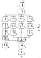
- Fig. 1 shows, in a simplified block diagram form, an HD-MAC 3 branch encoder in accordance with a preferred embodiment of the invention.
- Fig. 2 illustrates the characteristics of the two-dimensional filters 3, 4, 5 of Fig. 1.
- Fig. 3 illustrates subsampling patterns for each of transmission modes of 80 msec, 40 msec, and 20 msec.
- Fig. 4 illustrates a result of the subsampling and line shuffling for the 80 msec transmission mode.
- Fig. 5 shows five different routes per basic period of 80 msec used in a block route controller.
- the present embodiment is emloyed for an HD-MAC system, namely it is intended to transmit images emanating from generators with 1152 useful lines, each having 1440 pixels, by using only one video pass band equal to that of a standard TV transmission system of 625 lines(576 useful lines of 720 pixels).
- Fig. 1 there is shown one preferred embodiment of 3 branch encoder which incorporates the present invention.
- the input signal originates from a camera 1 working on 1250 lines, 50Hz, 2:1 interlaced with a 16:9 aspect ratio.
- the encoder consists of three branches, one for each mode.
- the 80 msec branch comprises a two-dimensional filter 3 whose charcteristic is shown in line a of Fig. 2, and a sampling circuit 6 for subsampling of each field of an image to provide the 80 msec transmission mode, and a line shuffler 9.
- the 40 msec branch comprises a two-dimensional filter 4 whose characteristic is shown in line b of Fig. 2, and a sampling circuit 7 for subsampling of each field of the image to provide the 40 msec transmission mode.
- the 20 msec branch comprises a two-dimensional filter 5 whose characteristic is shown in line c of Fig. 2, and a sampling circuit 8 for subsampling of each field of the image to provide the 20 msec transmission mode and a line shuffler 10.
- Fig. 3 shows, for the purpose of illustration, the three sampling structures: in (a),(c) and (e), the spatial position of the used samples is indicated by an 'X'; in(b),(d) and (f), the transmission field number of each sample is indicated.
- the subsampling is shown per field in the left-hand column and the result of the line shuffling is shown in the right-hand column for the 80 msec case. It should be noted that no line shuffling is needed for the 40 msec mode because only 625 lines out of 1250 are transmitted.
- the line shuffling for the 20 msec case is equivalent to the line shuffling for the 80 msec mode.
- Switch(SW1) selects the correct branch on a block basis with a control signal from a block route controller 18.
- Nyquist filter 11 then shapes the spectrum into a desired form.
- the signal emitting at the output of the encoder is in 625 lines, 50 Hz and 2:1 interlaced.
- the input video signal from an A/D converter 2 is also passed to a FFT(Fast Fourier Transform) unit 15.
- the FFT unit performs conventional FFT operaticns for the signal sequence of each block in each successive television field.
- the resulting FFT signals are forwarded to a phase shift detection unit 16.
- a phase shift detection is based on a well known shift property of the DFT(Discrete Fourier Transform).
- DFT Discrete Fourier Transform
- the shifted signal sequence of the corresponding block in the next successive field by h in row and i in column entails a phase shift to its transform counterpart as follows: f(m + h, n + i) ⁇ F(u, ⁇ ) exp (-j2 ⁇ (hu + i ⁇ ) /16)
- the phase shift unit 16 generates a phase shift(and then, a value l) for each block in each successive field by comparing the FFT of the signal sequence of the block in the field with the FFT of the signal sequence of the corresponding block in the previous field.
- the resulting l values will be forwarded to a mode decision unit 17.
- the mode will be decided in accordance with following criteria:
Landscapes
- Engineering & Computer Science (AREA)
- Multimedia (AREA)
- Signal Processing (AREA)
- Compression Or Coding Systems Of Tv Signals (AREA)
- Television Systems (AREA)
- Television Signal Processing For Recording (AREA)
Description
- The present invention relates to an apparatus for encoding a television signal having at least two successive fields including a first and a second succesive field, each field being divided into a plurality of image blocks, comprising: a first branch for subsampling the second succesive field to provide a first transmission mode for each of said image blocks; a second branch for subsampling the second successive field to provide a second transmission mode for each of said image blocks; a third branch for subsampling the second successive field to provide a third transmission mode for each of said image blocks; switching means for selectively coupling one of said branches with an outgoing channel; and means for generating a control signal for each of said image blocks of the second successive field to control said switching means, said control signal being dependent on the amount of movement of an image block.
- One of the common problems that arise in connection with the transmission of HDTV signals is that the broadcast channels are too narrow. In case of HD-MAC, for example, a bandwidth reduction by a factor of about four is to be expected. Another problem is the demand that the transmitted signal is compatible with the MAC/packet family so as to enable normal MAC receivers to receive the HDTV signals. This demand adds an extra constraint to the bandwidth reduction problem.
- It is known in the art that the above problems can be dealt with by means of reducing the diagonal frequency components in an image being transmitted and using different 'refresh' frequencies (transmission modes) for the stationary and the moving parts(blocks) of the image being transmitted.
- In order to use different refresh frequencies for different parts of the image, certain motion estimation for each part of the image should be conducted. Based on the motion estimation one may decide which refresh frequency may be used for a given part of the image.
- Conventionally, the motion estimation was based on a spatial distance between a part of the first frame out of pairs of television frames and a corresponding part of the second frame out of said pairs of television frames. One such device is disclosed in United States Patent US-A-5,036,392 issued to Janssen et al.
- Another device is disclosed in the article "Movement Processing for an HD-MAC Coding System" from J. van der Meer et al., in: Signal Processing of HDTV, Proceedings of the Second International Workshop on Signal Processing of HDTV, 29. February 1988, L'Aquila (IT), pages 337-344. This article is directed to the motion processing for an HD-MAC coding system according to the generic portion of
claim 1. Motion is detected by comparing the spatial sample difference in adjacent frames and based thereon block motion is determined. Depending on the block motion a motion processor identifies one of three motion modes and the HD-MAC coding system transmits a corresponding signal. - A problem with using the spatial distance for the motion estimation lies in the high computational complexity involved.
- Another problem with using the spatial distance for the motion estimation is that precise motion estimation cannot be always expected, which may result in incorrect refresh frequencies and also poor display of the image.
- These and other problems encountered in employing spatial distance estimation method are overcome by employing an encoder in accordance with the present invention, that is, that the present invention provides an apparatus for encoding a television signal having at least two successive fields including a first and a second successive field, each field being divided into a plurality of image blocks, comprising: a first branch for subsampling the second successive field to provide a first transmission mode for each of said image blocks; a second branch for subsampling the second successive field to provide a second transmission mode for each of said image blocks; a third branch for subsampling the second successive field to provide a third transmission mode for each of said image blocks; switching means for selectively coupling one of said branches with an outgoing channel; and means for generating a control signal for each of said image blocks of the second successive field to control said switching means, said control signal being dependent on the amount of movement of an image block, whereby said generating means are designed for generating the control signal in association with a phase shift between a frequency domain signal of each of said image blocks in the second successive field and a frequency domain signal of a corresponding image block in the first field.
- Fig. 1 shows, in a simplified block diagram form, an HD-
MAC 3 branch encoder in accordance with a preferred embodiment of the invention. - Fig. 2 illustrates the characteristics of the two-
dimensional filters - Fig. 3 illustrates subsampling patterns for each of transmission modes of 80 msec, 40 msec, and 20 msec.
- Fig. 4 illustrates a result of the subsampling and line shuffling for the 80 msec transmission mode.
- Fig. 5 shows five different routes per basic period of 80 msec used in a block route controller.
- For the purpose of illustration, the present embodiment is emloyed for an HD-MAC system, namely it is intended to transmit images emanating from generators with 1152 useful lines, each having 1440 pixels, by using only one video pass band equal to that of a standard TV transmission system of 625 lines(576 useful lines of 720 pixels).
- Referring now to Fig. 1, there is shown one preferred embodiment of 3 branch encoder which incorporates the present invention. The input signal originates from a
camera 1 working on 1250 lines, 50Hz, 2:1 interlaced with a 16:9 aspect ratio. The encoder consists of three branches, one for each mode. - The 80 msec branch comprises a two-
dimensional filter 3 whose charcteristic is shown in line a of Fig. 2, and asampling circuit 6 for subsampling of each field of an image to provide the 80 msec transmission mode, and aline shuffler 9. The 40 msec branch comprises a two-dimensional filter 4 whose characteristic is shown in line b of Fig. 2, and asampling circuit 7 for subsampling of each field of the image to provide the 40 msec transmission mode. The 20 msec branch comprises a two-dimensional filter 5 whose characteristic is shown in line c of Fig. 2, and asampling circuit 8 for subsampling of each field of the image to provide the 20 msec transmission mode and aline shuffler 10. - For the transmission of video signals, three different modes are used: namely, 80 msec mode for the stationary mode, 40 msec mode for the slowly moving mode and 20 msec mode for the moving mode. The three different modes employ three different sampling structures, respectively. Fig. 3 shows, for the purpose of illustration, the three sampling structures: in (a),(c) and (e), the spatial position of the used samples is indicated by an 'X'; in(b),(d) and (f), the transmission field number of each sample is indicated. In Fig. 4, the subsampling is shown per field in the left-hand column and the result of the line shuffling is shown in the right-hand column for the 80 msec case. It should be noted that no line shuffling is needed for the 40 msec mode because only 625 lines out of 1250 are transmitted. The line shuffling for the 20 msec case is equivalent to the line shuffling for the 80 msec mode.
- Switch(SW1) selects the correct branch on a block basis with a control signal from a
block route controller 18. Nyquistfilter 11 then shapes the spectrum into a desired form. The signal emitting at the output of the encoder is in 625 lines, 50 Hz and 2:1 interlaced. - The input video signal from an A/
D converter 2 is also passed to a FFT(Fast Fourier Transform)unit 15. The FFT unit performs conventional FFT operaticns for the signal sequence of each block in each successive television field. The resulting FFT signals are forwarded to a phaseshift detection unit 16. - A phase shift detection is based on a well known shift property of the DFT(Discrete Fourier Transform). In a finite-area sequence f(m,n)(wherein m,n represent pixel positions in a block with the row index interval 0 ≤ m ≤ 16-1 and the column index interval 0 ≤ n ≤ 16-1) for the video signal sequence of a block in a field with its transform F(u,υ )(wherein u = 2πm/16, υ = 2πn/16), the shifted signal sequence of the corresponding block in the next successive field by h in row and i in column entails a phase shift to its transform counterpart as follows:

- Should one define ℓ and θ as




Therefore, the value ℓ can be determined by solving the above equations. - The
phase shift unit 16 generates a phase shift(and then, a value ℓ) for each block in each successive field by comparing the FFT of the signal sequence of the block in the field with the FFT of the signal sequence of the corresponding block in the previous field. The resulting ℓ values will be forwarded to amode decision unit 17. - As is stated above, there are 80 msec mode, 40 msec mode, and 20 msec mode. The mode will be decided in accordance with following criteria:
- 80 msec mode for 0 ≤ ℓ ≤ 0.5
- 40 msec mode for 0.5 < ℓ ≤ 1.5
- 20 msec mode for ℓ > 1.5
Claims (6)
- An apparatus for encoding a television signal having at least two successive fields including a first and a second successive field, each field being divided into a plurality of image blocks, comprising:- a first branch (3, 6, 9) for subsampling the second successive field to provide a first transmission mode for each of said image blocks;- a second branch (4, 7) for subsampling the second successive field to provide a second transmission mode for each of said image blocks;- a third branch (5, 8, 10) for subsampling the second successive field to provide a third transmission mode for each of said image blocks;- switching means (SW1) for selectively coupling one of said branches with an outgoing channel; and- means (15-18) for generating a control signal for each of said image blocks of the second successive field to control said switching means (SW1), said control signal being dependent on the amount of movement of an image block,characterized in that
said generating means (15-18) are designed for generating the control signal in association with a phase shift between a frequency domain signal of each of said image blocks in the second successive field and a frequency domain signal of a corresponding image block in the first field. - The apparatus of claim 1, wherein said means (15-18) for generating said control signal comprises:
means (15) for transforming each of said image blocks to said frequency domain signal, and means (16) for calculating said phase shift between said frequency domain signals. - The apparatus of claim 2, wherein said means (15) for transforming is a Fast Fourier Transform unit.
- The apparatus as of claim 3, wherein each of said image blocks has a predetermined number of pixels arranged in the form of a matrix, said frequency domain signal for each of said image blocks in said second successive field is


and wherein ℓ =
- The apparatus of claim 4, wherein said means (15-18) for generating said control signal generates a transmission mode selection signal in response to the ℓ value.
- The apparatus of claim 5, wherein said means (15-18) for generating said control signal generates the first transmission mode selection signal when 0 ≤ ℓ ≤ 0.5, the second transmission mode selection signal when 0.5 < ℓ ≤ 1.5 and the third transmission mode selection signal when said ℓ is above 1.5.
Applications Claiming Priority (2)
| Application Number | Priority Date | Filing Date | Title |
|---|---|---|---|
| KR1019910017460A KR940008808B1 (en) | 1991-10-05 | 1991-10-05 | Hd-mac system |
| KR9117460 | 1991-10-05 |
Publications (3)
| Publication Number | Publication Date |
|---|---|
| EP0536666A2 EP0536666A2 (en) | 1993-04-14 |
| EP0536666A3 EP0536666A3 (en) | 1993-11-10 |
| EP0536666B1 true EP0536666B1 (en) | 1997-12-29 |
Family
ID=19320830
Family Applications (1)
| Application Number | Title | Priority Date | Filing Date |
|---|---|---|---|
| EP92116956A Expired - Lifetime EP0536666B1 (en) | 1991-10-05 | 1992-10-05 | A 3 branch encoder for the transmission of high resolution television signals |
Country Status (3)
| Country | Link |
|---|---|
| EP (1) | EP0536666B1 (en) |
| KR (1) | KR940008808B1 (en) |
| DE (1) | DE69223725T2 (en) |
Family Cites Families (2)
| Publication number | Priority date | Publication date | Assignee | Title |
|---|---|---|---|---|
| DE3682068D1 (en) * | 1986-03-19 | 1991-11-21 | British Broadcasting Corp | TELEVISION MOTION MEASUREMENT. |
| DE69017061T2 (en) * | 1989-04-12 | 1995-09-07 | Philips Electronics Nv | Interpolation circuit for an image signal. |
-
1991
- 1991-10-05 KR KR1019910017460A patent/KR940008808B1/en not_active Expired - Fee Related
-
1992
- 1992-10-05 EP EP92116956A patent/EP0536666B1/en not_active Expired - Lifetime
- 1992-10-05 DE DE69223725T patent/DE69223725T2/en not_active Expired - Lifetime
Also Published As
| Publication number | Publication date |
|---|---|
| DE69223725D1 (en) | 1998-02-05 |
| EP0536666A3 (en) | 1993-11-10 |
| EP0536666A2 (en) | 1993-04-14 |
| KR940008808B1 (en) | 1994-09-26 |
| DE69223725T2 (en) | 1998-04-16 |
| KR930009409A (en) | 1993-05-22 |
Similar Documents
| Publication | Publication Date | Title |
|---|---|---|
| CA1213359A (en) | Multiplex subsampling transmission system for a high definition color television picture signal | |
| CA1244934A (en) | Television signal processing system | |
| US4168509A (en) | Method for transmitting and receiving compatible high resolution television pictures | |
| US4713688A (en) | Method for increasing resolution in a compatible television system | |
| US4989091A (en) | Scan converter for a high definition television system | |
| CN87106645A (en) | Method and apparatus for detecting picture motion in a television signal | |
| US4845561A (en) | Field interleaving compatible high definition television transmission system | |
| US5136379A (en) | Video signal processing device capable of vertical blocking | |
| WO1991011073A2 (en) | Field-rate upconversion of television signals | |
| US4912556A (en) | Apparatus for compensating contour of television signal | |
| JPH043151B2 (en) | ||
| JPH02504214A (en) | A decoding device for signals representing a series of images and a high-definition television image transmission system including the same. | |
| US4901149A (en) | Method and apparatus for providing an enhanced television signal | |
| US5298994A (en) | Television signal converter for converting high definition television (HDTV) signals to conventional television signals | |
| US4635114A (en) | Adaptive television transmission system | |
| EP0536666A2 (en) | A 3 branch encoder for the transmission of high resolution television signals | |
| NL8902828A (en) | MOTION DETECTION SYSTEM FOR A HIGH DEFINITION TELEVISION RECEIVER. | |
| US5216505A (en) | Scanning line interpolation circuit | |
| CA2068719C (en) | Transmission system | |
| JPS63245085A (en) | Subsample interpolating method | |
| GB2195216A (en) | Video transmission system | |
| EP0931416B1 (en) | Video signal processing | |
| AU1690992A (en) | Method and apparatus for video signal bandwidth reduction with high quality compatible signal | |
| US6414718B1 (en) | DE-interlacing a video signal representing interlaced fields | |
| JPH0518518B2 (en) |
Legal Events
| Date | Code | Title | Description |
|---|---|---|---|
| PUAI | Public reference made under article 153(3) epc to a published international application that has entered the european phase |
Free format text: ORIGINAL CODE: 0009012 |
|
| AK | Designated contracting states |
Kind code of ref document: A2 Designated state(s): DE FR GB NL |
|
| PUAL | Search report despatched |
Free format text: ORIGINAL CODE: 0009013 |
|
| AK | Designated contracting states |
Kind code of ref document: A3 Designated state(s): DE FR GB NL |
|
| 17P | Request for examination filed |
Effective date: 19940510 |
|
| 17Q | First examination report despatched |
Effective date: 19960220 |
|
| GRAG | Despatch of communication of intention to grant |
Free format text: ORIGINAL CODE: EPIDOS AGRA |
|
| GRAG | Despatch of communication of intention to grant |
Free format text: ORIGINAL CODE: EPIDOS AGRA |
|
| GRAH | Despatch of communication of intention to grant a patent |
Free format text: ORIGINAL CODE: EPIDOS IGRA |
|
| GRAH | Despatch of communication of intention to grant a patent |
Free format text: ORIGINAL CODE: EPIDOS IGRA |
|
| GRAA | (expected) grant |
Free format text: ORIGINAL CODE: 0009210 |
|
| AK | Designated contracting states |
Kind code of ref document: B1 Designated state(s): DE FR GB NL |
|
| REF | Corresponds to: |
Ref document number: 69223725 Country of ref document: DE Date of ref document: 19980205 |
|
| ET | Fr: translation filed | ||
| PLBE | No opposition filed within time limit |
Free format text: ORIGINAL CODE: 0009261 |
|
| 26N | No opposition filed | ||
| REG | Reference to a national code |
Ref country code: GB Ref legal event code: IF02 |
|
| REG | Reference to a national code |
Ref country code: GB Ref legal event code: 732E |
|
| NLS | Nl: assignments of ep-patents |
Owner name: DAEWOO ELECTRONICS CORPORATION |
|
| REG | Reference to a national code |
Ref country code: FR Ref legal event code: TP |
|
| PGFP | Annual fee paid to national office [announced via postgrant information from national office to epo] |
Ref country code: FR Payment date: 20110920 Year of fee payment: 20 Ref country code: GB Payment date: 20110909 Year of fee payment: 20 |
|
| PGFP | Annual fee paid to national office [announced via postgrant information from national office to epo] |
Ref country code: NL Payment date: 20110922 Year of fee payment: 20 |
|
| PGFP | Annual fee paid to national office [announced via postgrant information from national office to epo] |
Ref country code: DE Payment date: 20110908 Year of fee payment: 20 |
|
| REG | Reference to a national code |
Ref country code: DE Ref legal event code: R071 Ref document number: 69223725 Country of ref document: DE |
|
| REG | Reference to a national code |
Ref country code: DE Ref legal event code: R071 Ref document number: 69223725 Country of ref document: DE |
|
| REG | Reference to a national code |
Ref country code: NL Ref legal event code: V4 Effective date: 20121005 |
|
| REG | Reference to a national code |
Ref country code: GB Ref legal event code: PE20 Expiry date: 20121004 |
|
| PG25 | Lapsed in a contracting state [announced via postgrant information from national office to epo] |
Ref country code: GB Free format text: LAPSE BECAUSE OF EXPIRATION OF PROTECTION Effective date: 20121004 |
|
| REG | Reference to a national code |
Ref country code: FR Ref legal event code: TP Owner name: MAPLE VISION TECHNOLOGIES INC., CA Effective date: 20131226 |