EP0534732B1 - Downhole sampling apparatus - Google Patents
Downhole sampling apparatus Download PDFInfo
- Publication number
- EP0534732B1 EP0534732B1 EP92308658A EP92308658A EP0534732B1 EP 0534732 B1 EP0534732 B1 EP 0534732B1 EP 92308658 A EP92308658 A EP 92308658A EP 92308658 A EP92308658 A EP 92308658A EP 0534732 B1 EP0534732 B1 EP 0534732B1
- Authority
- EP
- European Patent Office
- Prior art keywords
- chamber
- piston
- tubing
- annulus
- valve
- Prior art date
- Legal status (The legal status is an assumption and is not a legal conclusion. Google has not performed a legal analysis and makes no representation as to the accuracy of the status listed.)
- Expired - Lifetime
Links
Images




Classifications
-
- E—FIXED CONSTRUCTIONS
- E21—EARTH OR ROCK DRILLING; MINING
- E21B—EARTH OR ROCK DRILLING; OBTAINING OIL, GAS, WATER, SOLUBLE OR MELTABLE MATERIALS OR A SLURRY OF MINERALS FROM WELLS
- E21B23/00—Apparatus for displacing, setting, locking, releasing or removing tools, packers or the like in boreholes or wells
- E21B23/004—Indexing systems for guiding relative movement between telescoping parts of downhole tools
- E21B23/006—"J-slot" systems, i.e. lug and slot indexing mechanisms
-
- E—FIXED CONSTRUCTIONS
- E21—EARTH OR ROCK DRILLING; MINING
- E21B—EARTH OR ROCK DRILLING; OBTAINING OIL, GAS, WATER, SOLUBLE OR MELTABLE MATERIALS OR A SLURRY OF MINERALS FROM WELLS
- E21B34/00—Valve arrangements for boreholes or wells
- E21B34/06—Valve arrangements for boreholes or wells in wells
- E21B34/10—Valve arrangements for boreholes or wells in wells operated by control fluid supplied from outside the borehole
- E21B34/108—Valve arrangements for boreholes or wells in wells operated by control fluid supplied from outside the borehole with time delay systems, e.g. hydraulic impedance mechanisms
-
- E—FIXED CONSTRUCTIONS
- E21—EARTH OR ROCK DRILLING; MINING
- E21B—EARTH OR ROCK DRILLING; OBTAINING OIL, GAS, WATER, SOLUBLE OR MELTABLE MATERIALS OR A SLURRY OF MINERALS FROM WELLS
- E21B49/00—Testing the nature of borehole walls; Formation testing; Methods or apparatus for obtaining samples of soil or well fluids, specially adapted to earth drilling or wells
- E21B49/08—Obtaining fluid samples or testing fluids, in boreholes or wells
- E21B49/081—Obtaining fluid samples or testing fluids, in boreholes or wells with down-hole means for trapping a fluid sample
- E21B49/0813—Sampling valve actuated by annulus pressure changes
Definitions
- This invention relates to a downhole sampling apparatus for collecting samples in a wellbore.
- the lower end of the metering chamber below the metering cartridge is communicated with well annulus pressure, and a second floating piston separates the oil in the metering chamber from well fluid which enters the lower end of the metering chamber.
- An increase in well annulus pressure is immediately communicated to the upper surface of the power piston, but is delayed for a significant period of time in being fully communicated to the lower side of the power piston, so that a rapid increase in well annulus pressure will cause a downward pressure differential across the power piston to move the power piston and actuate the tool.
- a downhole sampling apparatus for positioning within a wellbore on a tubing string which forms with the wellbore an annulus
- the apparatus comprising a cylindrical housing having a portion defining a first annulus port: a first power piston slidably disposed within said cylindrical housing movable between an initial position and a second position, said first power piston being responsive to an increase in the annulus pressure as communicated through said first annulus port to move said power piston from the initial position to the second position; a concentric housing disposed within said cylindrical housing and containing a plurality of tubing ports: means for biasing said first power piston so that as annulus pressure is released, said first power piston returns to the initial position: a first and second case located within said cylindrical housing, said first chamber case being exposed to tubing hydrostatic pressure and wherein said first case has contained therein oil and said second chamber case has contained a gas initially at atmospheric pressure: valve means, located between said atmospheric chamber case and said oil chamber case, for controlling flow of the oil to the gas chamber, said valve means
- the valve means comprises a first stem containing ; passageway bored therethrough and a transverse port intersecting the passageway. Attached to the stem is a cylindrical body assembly containing a passageway and impedance means for impeding the flow of fluid in the passageway. Also included is a second stem having a cavity with a transverse port so that the first stem and second stem are operatively associated and wherein the second stem is slidably disposed within the passageway that communicates with the tubing internal diameter so that the second stem is responsive to hydrostatic pressure changes within the passageway.
- the valve actuating means may contain an operating mandrel slidably disposed within the cylindrical housing and sealingly isolating the tubing port, and a passageway leading from the tubing port.
- Ratchet means may also be provided on the operating mandrel and power piston for selective longitudinal movement with the power piston so that as the power piston moves down, the operating mandrel will also move down, but as the power piston is biased back up, the operating mandrel remains stationary.
- An advantage of the invention is that it allows for selectively exposing the tubing ports at a time and location determined by the operator. Another advantage is the repositioning of the power piston to its original position by the release of annular hydrostatic pressure. Still another advantage is the placement of multiple samplers in the downhole workstring.
- Another advantage includes having annular hydrostatic pressure control operation of the mandrel and having tubular pressure control the actuation means. Yet another advantage includes the use of a rupture disc which can be selected at a desired burst strength before the tool is run into the wellbore. Still another advantage includes use of electronic means which allows activation of the valve means based on pressure signals in the wellbore annulus.
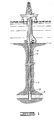
- Fig. 1 is a schematic diagram depicting an environment in which a preferred embodiment of the present invention is particularly adapted for use.
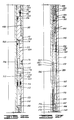
- Figs. 2A-2K form a longitudinal sectional view of a preferred embodiment of the present invention, wherein annular pressure has been applied.
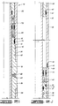
- Fig. 3 is a longitudinal sectional view of a portion of the embodiment shown in Fig. 2D, but after a tubing port has been exposed.
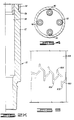
- Fig. 4 is a cut-through section of the apparatus taken along line A-A of Fig. 2C, showing the multiple samplers placed about the periphery of the tool.
- Fig. 5 is an unwrapped profile of the inner component of the ratchet means of the preferred embodiment.
- the downhole sampler 2 is lowered into the wellbore 4 by means of a workstring 6.
- the wellbore penetrates an oil and gas reservoir 8, and as will be appreciated by those skilled in the art, the well may penetrate several zones (not shown). Packer means 10, to isolate the reservoir, will be emploved.
- the operator may wish to obtain a sample from the oil and gas reservoir, then flow the well for a period of time, then obtain a second sample.
- the operator may wish to position the sampler at a second location in order to sample a second reservoir.
- the illustrated embodiment of the invention generally comprises a lower sub 20 which contains on the outer diameter wrenching flats 22. Extending therefrom is cylindrically flat surface 24, which has in turn radially flat shoulder 26, and extending therefrom is external thread means 28 with elastomeric seal means 30 seated in recessed groove 32.
- the lower sub 20 contains a first and second groove, respectively 34 and 36, with internal diameter bore 38 leading therefrom.
- Oil chamber case 40 on the outer diameter, has a first annulus port 42 bored therethrough, as well as oil fill port 44 which has placed therein a suitable plug 45 with thread means 46 for containing the oil placed in case 40. Also contained on the oil chamber case 40 are wrenching flats 48. Extending radially inward, the tool includes internal thread means 50, having in turn internal bore 52, which extends to the second internal thread means 54.
- spacer sub 56 is threadedly attached to the oil chamber case 40 by means of external thread means 58, which has extending therefrom a recessed groove 60 for placement of an elastomeric seal means 62.
- the spacer sub 56 has, on the external portion thereof, an oil fill port 64 with accompanying plug 66.
- the spacer sub 56 terminates with external thread means 68, which has in turn, sealing bore 70 with groove 72 for placement of elastomeric seal member 74. Extending radially inward is internal bore 76.
- Nitrogen chamber case 78 has a generally cylindrical outer surface 80 which has in turn winching flats 82. With reference to Fig. 2G, extending radially inward is sealing bore 84 which has in turn internal thread means 86. Chambered shoulder 88 has extending therefrom internal bore 90 which terminates at second chambered shoulder 92 and internal thread means 94.
- Nitrogen chamber case top sub seen generally at 96 on Fig. 2G, comprises on the outer diameter, an external thread means 98 which has in turn a sealing bore 100 with elastomeric seal members 102 placed therein. Extending therefrom is outer cylindrical surface 104 containing wrenching flats 106 terminating at angled shouldered 108 which has extending therefrom sealing bore 110 and recess 112, with elastomeric members 114 contained therein. External thread means 116 terminate at radially flat surface 118.
- Sealing bore 122 further comprises: an exit port 128 which forms the exit of passageway 130; a second recess 132 which contains elastomeric member 134; and, radially flat shoulder 136.
- the internal diameter of the nitrogen chamber case 96 also contains a second surface 138 which has in turn chambered surface 140 and internal thread means 142, third surface 144, and fourth surface 146.
- An internal mandrel 148 comprises on the outer periphery a first chambered surface 150, external thread means 152, second chambered surface 154, cylindrical surface 156, radially extending shoulder 158, (external thread means 160), and having in turn first cylindrical bore 162.
- the nitrogen chamber case 78 and internal mandrel 148 form the nitrogen chamber case for holding pressured nitrogen.
- the nitrogen piston 168 is slidably disposed within case 78.
- means for impeding the oil, which is enclosed in the bottom chamber case 40, is provided generally at 170.
- An impeding means which may be used is the Lee Visco Jet disclosed in U.S. patent specification no. 3,323,550 to which reference should be made.
- the outer cylindrical housing 172 seen in Fig. 2E, comprises on the outer diameter a first annulus port 174 and a second port 176, with a radially inward extending shoulder 178. Oil fill port 175 and the receptacle plug 177 are also contained thereon.
- the outer cylindrical housing 172 also contains external thread means 180 and sealing bore 182, with sealing bore 182 containing recess 184 and elastomeric seal member 186.
- radially flat shoulder 188 has bored therethrough tubing passageway 190 of first diameter and passageway 192 of second diameter, which is transversed by a third passageway 194 which is communicated with the internal diameter of the outer cylindrical housing 172.
- the outer cylindrical housing 172 has, on the internal diameter, a first surface 196 and second surface 198 which has in turn a plurality ports such as port 194 which have been defined on the internal diameter, and a plurality of elastomeric seal means 196, 198, 200 and 202 which surround the plurality of ports.
- a recessed groove 204 which contains elastomeric seal means 206 is also provided for sealing.
- the remainder of the inner diameter of the outer cylindrical housing contains: a chambered shoulder 208, third surface 210 which contains port 175, chambered shoulder 212, fourth surface 214 which includes port 174, and terminates with external thread means 216.
- the power piston 300 is slidably disposed within the outer cylindrical housing 172.
- the power piston 300 includes on the outer periphery a first surface 302, second surface 304, third surface 306, and fourth surface 308.
- the fourth surface contains a first recess groove 310 and a second groove 312, along with elastomeric members 314, and 316, respectively.
- the fifth surface 318 contains bored through port 320 and terminates with external thread means 322.
- the ratchet means is seen at 324, and generally comprises an outer component 326, an inner component 328, and ball 330. Referring to Fig. 5, the unwrapped profile of the inner component 328 is shown. As those skilled in the art will appreciate, the ball element 330 located in the outer component 326 will travel within this profile as the power piston is urged longitudinally up or down. A more complete detailed description will follow in the operation of the sampler.
- the outer component 326 of the ratchet means is threadedly secured to the upper power piston 300 with internal thread means 329, and to the lower power piston 331 with external thread means 332.
- the lower power piston 331 includes on the outer diameter a first surface 334 which contain wrenching flats 336, and fluid port 338.
- a first surface 340 contains the fluid port 338, a chamfered surface 342, a second surface 344, a second chamfered surface 346, and third surface 348, concluding with internal thread means 350.
- the operating mandrel 352 includes on the outer periphery a first surface 354 which contains a recessed groove 355 and terminates at shoulder 356.
- the second surface 358 contains a plurality angled grooves 360 and wrenching flats 362, and terminates at snoulder 364.
- the collet 366 includes on the outer diameter external thread means 368 which threadedly mate with the thread means 120. Extending therefrom is first surface 370, chamfered shoulder 372, second surface 374, second surface 376 and chamfered terminating end 378. Extending radially inward is first surface 380 and flat end 382 which in turn has a chamfered profile 384, that leads to internal surface 386, shoulder 388 and surface 390.
- an upper housing member 400 comprises a first surface 402, with wrenching flats 404 contained thereon. Extending radially inward is internal thread means 406 leading to first bore surface 408 which has in turn a second internal thread means 410.
- the invention also contains a plurality of means for sampling which generally contains a plurality of atmospheric chamber cases, in series with oil chamber cases followed by a sample chamber.
- the air chamber case is generally seen at 450.
- the first surface 452 is a cylindrical housing with wrenching flats 454, which in turn has a radially flat shoulder 456 and extending therefrom is a second surface 458.
- recess 460 Contained on the second surface 458 is recess 460 which contains elastomeric member 462.
- Case 450 has bored therethrough a center passageway 464.
- Center passageway 464 has a surface 466 of a first diameter and a second surface 468 of increased diameter until cavity 470 is encountered.
- On the inner diameter of the cavity 470 is internal thread means 472.
- the valve means can be seen generally at 474 and comprises a first member 475a and second member 475b.
- the first member 475a includes: first cylindrical surface 476 which contains recess 478 and elastomeric member 480; shoulder 482; second cylindrical surface 484 that contains recess 486 and elastomeric seal member 488 therein, as well as transverse appendant 490, and terminates at angled end 492. Also, a passageway 494 is bored through the center of the valve 474.
- the second member 475b of the valve means includes: a first surface 498 with recess 500 and seal means 502 defined thereon; a chamfered shoulder 504 that has in turn a second surface 506 containing communication aperture 508. Internally thereof, an inner surface 510 forms a cavity so that end 492 can mate, and apertures 508, 490 may be positioned in alignment when valve means 475b has been urged axially upward in passageway 468.
- Means for impeding the flow of fluid is seen generally at 518.
- a restriction such as an orifice 519 is placed in the passageway.
- the fluid in oil chamber 524 is flowed to atmospheric chamber case 450, once the apertures 508 and 490 are placed in alignment, but the flow will be impeded because of the means for impeding the flow 518.
- a valve means case 512 is securely fastened to the air chamber case 450 with external thread means 514.
- the case On the internal diameter, the case contains a first surface and shoulder 516 wherein shoulder 516 and 482 abut.
- the impeding means 518 is threadedly secured to end cap 520 which will hold the impeding means in place.
- the end cap 520 has an internal bore surface 522.
- Case 524 includes: a first outer diameter surface 526; a first and second aperture 528 and 530; and a tubing pressure port 532.
- End cap 520 also includes wrenching flats 534, shoulder 536, external thread means 538 and smooth outer cylindrical surface 540 which contains elastomeric seal means 542.
- case 524 comprises a first smooth bore 544 which terminates at shoulder 546, with second smooth bore 548 extending therefrom, with bore 548 having apertures 528 and 530 disposed therethrough, terminating with internal thread means 550.
- the sampler chamber case 600 Attached to the oil chamber case 524 is the sampler chamber case 600, which in the preferred embodiment will be threadedly secured by internal thread means 602 to threads 538.
- internal thread means 602 On the outer periphery of the sampler case 600 is cylindrical surface 604 which contains apertures 606, 607 and recess 608, and terminates at shoulder 610. Extending radially inward, the case includes: internal thread means 612, smooth bore 614, and second internal thread means 616.
- sampler piston 618 Disposed within the sampler chamber case 600 is sampler piston 618, which generally comprises: a first end 620, second end 622, and an outer diameter surface 624 which contains a plurality of elastomeric seal members 626 and 628.
- the sampler piston 618 is slidably dispose within the case 600 so that as fluid from the workstring enters the case 600, the piston 618 will be urged longitudinally upward.
- the metering piston 630 includes: a first cylindrical surface 632; a first shoulder 634; a second cylindrical surface 635 containing elastomeric seal means 636; a second shoulder 638; and second cylindrical surface 640.
- the piston 630 also includes chambered surface 642 which extends to surface 644, which contains seal means 646. It should be noted that seal means 646, 656, 670, and 668 will sealingly engage bore 544.
- the piston 630 further comprises: a second chamfered surface 648 which extends to cylindrical surface 650 which has in turn chamfered surface 652; a third surface 654 containing seal means 656; and, shoulder 658.
- the piston has in turn fifth surface 660 which has aperture 662 therethrough, with surface 660 extending to shoulder 664.
- sixth cylindrical surface 666 contains elastomeric seal members 668 and 670, respectively.
- piston 630 Extending radially inward of piston 630 is internal bore 672 which terminates at conical end 674. Internal bore 672 intersects aperture 662 so that as piston 630 moves downward, aperture 662 will align with port 532 and bore 672 will provide a passageway for fluid in the tubing string to communicate with piston 618.
- Sampler case 600 will have attached intermediate sub 676 which is threadedly attached to the case 600 by means of external thread means 678.
- Sub 676 also contains internal bore 680.
- Top end sub 682 is securely attached to the sub 676, and the sampler chamber case is a completely enclosed vessel that can be removed with the sample ot fluid intact and without any lost in pressure after the workstring is retrieved from the wellbore.
- the apparatus will also contain a cylindrical sub 684, which will abut the top end sub 682.
- Top mandrel 686 will be threadedly attached to outer mandrel thread means 410 at external thread means 687.
- the outer cylindrical surface is seen at 688; also, there is included seal means 690 for sealing with bore 408.
- bore 692, and 694 provide a central flow area for fluids in the tubing string 6.
- there are four removable sample chambers 90, 92, 94, and 96 which move their upper ends received in top sub 684.
- the sample chambers 90,92,94,and 96 are located within the sample chamber housing section 400 at substantially equal elevations, and are circumferentially spaced from each other as shown in Fig. 4 about the longitudinal axis of the sampler apparatus 78.
- Fig. 3 shown a longitudinal sectional view of the embodiment shown in Fig. 2D; however, the operating mandrel 352 has been urged down so that port 194 has been exposed to the hydrostatic pressure of the workstring 6 and port 508 is now communicated with bore 494.
- Like numbers in Fig. 3 refer to like parts in Figs. 2A-2K.
- the bottom hole assembly will be lowered into the wellbore 4.
- the bottom hole assembly will contain a tester valve 12, packer means 10, the multiple sampler of the present invention 2, and other various tools as will be appreciated by those skilled in the art.
- a flow test (sometimes known as a drill stem test) will be preformed. This will be initiated by opening the tester valve.
- hydrocarbons will travel vertically upwards in the workstring 6. At some point, it will be necessary to shut-in the producing formation to observe the pressure build-up. When this occurs, hydrocarbons will be trapped in the workstring 6. At this point, a sample can be taken in one of the circumferentially positioned multiple samplers.
- annulus pressure is applied at the surface. This pressure will be transmitted to annulus ports 42, 174, and 176 which will act against piston 43 and power piston 300.
- Oil chamber case 40 has contained therein silicon oil which will, because of the piston 43, also transmits the hydrostatic pressure. This hydrostatic pressure will in turn be transmitted to the means for impeding the oil 170. Hydrostatic pressure will also be applied through annulus ports 174 and 176,which will act against power piston 300.
- the nitrogen piston 16 will act against the nitrogen in nitrogen chamber case 78.
- the nitrogen is set at a predetermined pressure before the tool is run into the well.
- the power piston 300 will in turn act against the nitrogen in case 78.
- the piston 43 is also transmitting pressure; however, due to the impeding means 170, the pressure on upper side of piston 168 will be less, thereby causing a pressure differential to move power piston 300 downward.
- the outer component ratchet means 326 will engage the inner, or receptacle, ratchet means 328 located on the operating mandrel 352.
- the operating mandrel will also move, thereby exposing the tubing port 194 to the hydrostatic pressure contained within the workstring 6, which before that time had been sealed by the operating mandrel 352 and elastomeric seal member 197.
- the pressure in the oil case and nitrogen case will equalize. Downward movement of the piston 300 will be limited by top surface 118 of top sub 96. Next, the operator can release the pressure to the annulus. This will cause the pressure in the oil chamber case to decrease, as well as the pressure in the second oil chamber case to decrease, but the pressure in the nitrogen chamber case will still be at an elevated level because of the impeding means.
- the pressure contained in the nitrogen case 78 will act to move pistons 168 and 43; however, because of the impeding means 170, the power piston 300 will first move longitudinally upward.
- the ratchet means 324 will allow the piston 300 to move, but the operating mandrel 352 will not.
- the ball element 330 will be traveling in the track 900 (also known as the slotted groove), and will not shoulder so that the operating mandrel remains stationary and port 194 will remain exposed.
- the ball element 330 will travel in accordance with the movement of the power piston 300 and the outer component 328.
- the power piston stroke (longitudinal length of travel) with respect to the operating mandrel 352 is 2.5" (6.35cm).
- the amount of downward longitudinal travel permitted in the track 900, due to the length of the track, is 2.0" (5.08cm).
- the ball 330 will travel in the track 900, located on the inner component 328.
- the ball 330 will shoulder at 902 after the piston 300 has moved longitudinally downward 2.0" (5.08cm), thereby causing downward movement of the operating mandrel 352 a half inch (1.27cm).
- the piston 300 moves back up, the ball will travel in the track 900, but because of the length of the track in this direction (2.5", 6.35cm), no movement will take place with respect to the operating mandrel 352.
- the ball 330 will be at position 904. The sequence is again repeated. Thus, pressure is again applied to the annulus, which will result in the power piston 300 movement longitudinally downward. The ball 330 will travel from position 904, in track 900, until the ball 330 shoulders at 906, which results in one-half inch (1.27cm) downward movement of inner component 328. This sequence is again repeated until all of the inner ports have been exposed to tubing pressure.
- the unwrapped view of the inner component 328 shows the configuration of the track 900 wherein downward longitudinal movement of the power piston 300 will result in the mandrel 352 movement down but upper movement of the piston 300 will result in the mandrel 352 remaining static.
- the mandrel 352 has disposed thereon grooves or teeth 360 which cooperate with the indexing collet 366.
- the chamfered profile 384 will engage in one of the grooves 360. This feature ensures that the operating mandrel 352 will not slide longitudinally upward as the piston 300 (and seal means 316) is urged axially upward.
- the numbers of grooves on the mandrel 352 will correspond to the number of tubing ports 194 included on the inner diameter of the cylindrical housing 172 which corresponds to the number of samplers placed abut the periphery of the tool 2.
- the hydrostatic pressure in the workstring will be allowed to enter the passageway 192 which will in turn transmits the fluid hydrostatic to passageway 190, and 464.
- This hydrostatic fluid pressure will work against the lower valve means seen generally at 496 and tend to urge the valve means longitudinally upward so that aperture 508 on the surface 506 will align with aperture 490, which is located on the valve means 474.
- aperture 490 and 508 have been aligned, oil contained in the oil chamber case 524 will be allowed to flow to the atmospheric chamber case 470.
- elastomeric seal means 656 will pass tubing port 532. While the piston 630 will continue to be urged downward, the fluid located inside the workstring will now be channeled to aperture 662 which is intersected by axial bore 672 which in turn provides a passageway for the tubing fluid to the sampler case 600.
- the sampler piston 618 will be unseated, and as the fluid continues to flow, the sampler piston 618 will continue to be urged longitudinally upward, and a fluid sample will be taken in the sample chamber case 600.
Landscapes
- Life Sciences & Earth Sciences (AREA)
- Engineering & Computer Science (AREA)
- Geology (AREA)
- Mining & Mineral Resources (AREA)
- Physics & Mathematics (AREA)
- Environmental & Geological Engineering (AREA)
- Fluid Mechanics (AREA)
- General Life Sciences & Earth Sciences (AREA)
- Geochemistry & Mineralogy (AREA)
- Sampling And Sample Adjustment (AREA)
Description
- This invention relates to a downhole sampling apparatus for collecting samples in a wellbore.
- Various types of samplers have been used in the past. For instance, in U.S. patent specification no. 4,903,765 (Zunkel), there is disclosed a delayed opening fluid sampler containing multiple sample chambers. The sampler is lowered into the wellbore on a workstring to the desired depth. According to the techniques taught by Zunkel, in order to begin operation, a sufficient amount of annulus pressure must be applied to shear a set of holding pins. A fluid restriction was provided so that a time delay is established between the period from applying annulus pressure and the collecting of the sample.
- Another type of fluid sampler is found in U.S. patent specification no. 4,665,983 (Ringgenberg). Again, this type of sampler is lowered into the wellbore to the desired depth, a port defined in the tool is opened in response to annulus pressure whereby the port admits well fluid into a sample chamber.
- We have also developed an annulus pressure responsive tool which operates in response to a relatively low annulus pressure increase as shown in U.S. patent specifications nos. 4,422,506 and 4,429,748 (Beck). These low pressure responsive tools have a power piston which is exposed to well annulus pressure from above, and which has its lower surface exposed to pressurized nitrogen gas in a nitrogen chamber located there below. Located below the nitrogen chamber is a metering chamber or equalizing chamber which is filled with oil. A floating piston separates the gas in the gas chamber from the oil in the metering chamber. Disposed in the metering chamber is a metering cartridge which provides a resistance to flow of oil therethrough. The lower end of the metering chamber below the metering cartridge is communicated with well annulus pressure, and a second floating piston separates the oil in the metering chamber from well fluid which enters the lower end of the metering chamber. An increase in well annulus pressure is immediately communicated to the upper surface of the power piston, but is delayed for a significant period of time in being fully communicated to the lower side of the power piston, so that a rapid increase in well annulus pressure will cause a downward pressure differential across the power piston to move the power piston and actuate the tool.
- In U.S. patent specification no. 4,667,743 (Ringgenberg and Beck), there is disclosed an annulus, low pressure responsive flow tester valve having a lug and slot ratchet means operably connecting the ball valve of the tool with power piston.
- In oil and gas operations, it is often desirable to retrieve multiple fluid samples taken at different time intervals. Moreover, the operator may wish to take multiple samples at different depth intervals in the wellbore. Prior art samplers simply have not been able to obtain multiple samples at different times and different intervals; therefore, there is a need in the industry for a sampler that can obtain multiple samples.
- We have now devised an improved downhole sampler apparatus.
- According to the present invention, there is provided a downhole sampling apparatus for positioning within a wellbore on a tubing string which forms with the wellbore an annulus, the apparatus comprising a cylindrical housing having a portion defining a first annulus port: a first power piston slidably disposed within said cylindrical housing movable between an initial position and a second position, said first power piston being responsive to an increase in the annulus pressure as communicated through said first annulus port to move said power piston from the initial position to the second position; a concentric housing disposed within said cylindrical housing and containing a plurality of tubing ports: means for biasing said first power piston so that as annulus pressure is released, said first power piston returns to the initial position: a first and second case located within said cylindrical housing, said first chamber case being exposed to tubing hydrostatic pressure and wherein said first case has contained therein oil and said second chamber case has contained a gas initially at atmospheric pressure: valve means, located between said atmospheric chamber case and said oil chamber case, for controlling flow of the oil to the gas chamber, said valve means having an open position and a closed position: valve actuating means, operably associated with said first power piston, for supplying tubing hydrostatic pressure to said valve means so that said valve means is placed in the opened position; and means for sampling a portion of fluid contained within said tubing string, said sampling means being responsive to said valve means.
- In one embodiment. the valve means comprises a first stem containing ; passageway bored therethrough and a transverse port intersecting the passageway. Attached to the stem is a cylindrical body assembly containing a passageway and impedance means for impeding the flow of fluid in the passageway. Also included is a second stem having a cavity with a transverse port so that the first stem and second stem are operatively associated and wherein the second stem is slidably disposed within the passageway that communicates with the tubing internal diameter so that the second stem is responsive to hydrostatic pressure changes within the passageway.
- The valve actuating means may contain an operating mandrel slidably disposed within the cylindrical housing and sealingly isolating the tubing port, and a passageway leading from the tubing port. Ratchet means may also be provided on the operating mandrel and power piston for selective longitudinal movement with the power piston so that as the power piston moves down, the operating mandrel will also move down, but as the power piston is biased back up, the operating mandrel remains stationary.
- An advantage of the invention is that it allows for selectively exposing the tubing ports at a time and location determined by the operator. Another advantage is the repositioning of the power piston to its original position by the release of annular hydrostatic pressure. Still another advantage is the placement of multiple samplers in the downhole workstring.
- Another advantage includes having annular hydrostatic pressure control operation of the mandrel and having tubular pressure control the actuation means. Yet another advantage includes the use of a rupture disc which can be selected at a desired burst strength before the tool is run into the wellbore. Still another advantage includes use of electronic means which allows activation of the valve means based on pressure signals in the wellbore annulus.
- In order that the invention may be more fully understood, reference is made to the accompanying drawings, wherein:
- Fig. 1 is a schematic diagram depicting an environment in which a preferred embodiment of the present invention is particularly adapted for use.
- Figs. 2A-2K form a longitudinal sectional view of a preferred embodiment of the present invention, wherein annular pressure has been applied.
- Fig. 3 is a longitudinal sectional view of a portion of the embodiment shown in Fig. 2D, but after a tubing port has been exposed.
- Fig. 4 is a cut-through section of the apparatus taken along line A-A of Fig. 2C, showing the multiple samplers placed about the periphery of the tool.
- Fig. 5 is an unwrapped profile of the inner component of the ratchet means of the preferred embodiment.
- Referring to Fig. 1, the
downhole sampler 2 is lowered into thewellbore 4 by means of aworkstring 6. The wellbore penetrates an oil andgas reservoir 8, and as will be appreciated by those skilled in the art, the well may penetrate several zones (not shown). Packer means 10, to isolate the reservoir, will be emploved. - The operator may wish to obtain a sample from the oil and gas reservoir, then flow the well for a period of time, then obtain a second sample. Alternatively, the operator may wish to position the sampler at a second location in order to sample a second reservoir.
- Referring to Fig. 2K, the illustrated embodiment of the invention generally comprises a
lower sub 20 which contains on the outerdiameter wrenching flats 22. Extending therefrom is cylindrically flat surface 24, which has in turn radiallyflat shoulder 26, and extending therefrom is external thread means 28 with elastomeric seal means 30 seated inrecessed groove 32. - With reference to Fig. 2J, extending radially inward, the
lower sub 20 contains a first and second groove, respectively 34 and 36, with internal diameter bore 38 leading therefrom. -
Oil chamber case 40, on the outer diameter, has afirst annulus port 42 bored therethrough, as well asoil fill port 44 which has placed therein asuitable plug 45 with thread means 46 for containing the oil placed incase 40. Also contained on theoil chamber case 40 are wrenchingflats 48. Extending radially inward, the tool includes internal thread means 50, having in turninternal bore 52, which extends to the second internal thread means 54. - Referring to Fig. 21,
spacer sub 56 is threadedly attached to theoil chamber case 40 by means of external thread means 58, which has extending therefrom arecessed groove 60 for placement of an elastomeric seal means 62. Thespacer sub 56 has, on the external portion thereof, anoil fill port 64 with accompanyingplug 66. Thespacer sub 56 terminates with external thread means 68, which has in turn, sealingbore 70 withgroove 72 for placement of elastomeric seal member 74. Extending radially inward isinternal bore 76. -
Nitrogen chamber case 78 has a generally cylindricalouter surface 80 which has inturn winching flats 82. With reference to Fig. 2G, extending radially inward is sealingbore 84 which has in turn internal thread means 86.Chambered shoulder 88 has extending therefrominternal bore 90 which terminates at second chamberedshoulder 92 and internal thread means 94. - Nitrogen chamber case top sub, seen generally at 96 on Fig. 2G, comprises on the outer diameter, an external thread means 98 which has in turn a
sealing bore 100 withelastomeric seal members 102 placed therein. Extending therefrom is outercylindrical surface 104 containing wrenchingflats 106 terminating at angled shouldered 108 which has extending therefrom sealing bore 110 andrecess 112, withelastomeric members 114 contained therein. External thread means 116 terminate at radiallyflat surface 118. - Extending radially inward from
surface 118 is internal thread means 120 which terminates at internal sealing bore 122, with sealingbore 122 containingrecess 124 withelastomeric seal members 126 positioned therein. - Sealing bore 122 further comprises: an
exit port 128 which forms the exit ofpassageway 130; asecond recess 132 which containselastomeric member 134; and, radiallyflat shoulder 136. The internal diameter of thenitrogen chamber case 96 also contains asecond surface 138 which has in turn chamberedsurface 140 and internal thread means 142,third surface 144, andfourth surface 146. - An
internal mandrel 148 comprises on the outer periphery a first chamberedsurface 150, external thread means 152, second chamberedsurface 154,cylindrical surface 156, radially extendingshoulder 158, (external thread means 160), and having in turn firstcylindrical bore 162. - Extending radially inward from the first
cylindrical surface 162 isinternal bore 166. - The
nitrogen chamber case 78 andinternal mandrel 148 form the nitrogen chamber case for holding pressured nitrogen. Thenitrogen piston 168 is slidably disposed withincase 78. Turning to Fig. 2I, means for impeding the oil, which is enclosed in thebottom chamber case 40, is provided generally at 170. An impeding means which may be used is the Lee Visco Jet disclosed in U.S. patent specification no. 3,323,550 to which reference should be made. - The outer
cylindrical housing 172, seen in Fig. 2E, comprises on the outer diameter afirst annulus port 174 and asecond port 176, with a radially inward extending shoulder 178.Oil fill port 175 and thereceptacle plug 177 are also contained thereon. The outercylindrical housing 172 also contains external thread means 180 and sealingbore 182, with sealingbore 182 containingrecess 184 andelastomeric seal member 186. - Turning to Fig. 2D, radially
flat shoulder 188 has bored therethroughtubing passageway 190 of first diameter andpassageway 192 of second diameter, which is transversed by athird passageway 194 which is communicated with the internal diameter of the outercylindrical housing 172. - The outer
cylindrical housing 172 has, on the internal diameter, afirst surface 196 andsecond surface 198 which has in turn a plurality ports such asport 194 which have been defined on the internal diameter, and a plurality of elastomeric seal means 196, 198, 200 and 202 which surround the plurality of ports. A recessedgroove 204 which contains elastomeric seal means 206 is also provided for sealing. - The remainder of the inner diameter of the outer cylindrical housing contains: a
chambered shoulder 208,third surface 210 which containsport 175, chambered shoulder 212,fourth surface 214 which includesport 174, and terminates with external thread means 216. - Referring to Fig. 2E, the
power piston 300 is slidably disposed within the outercylindrical housing 172. Thepower piston 300 includes on the outer periphery afirst surface 302,second surface 304,third surface 306, andfourth surface 308. The fourth surface contains afirst recess groove 310 and asecond groove 312, along withelastomeric members - The
fifth surface 318 contains bored throughport 320 and terminates with external thread means 322. - The ratchet means is seen at 324, and generally comprises an
outer component 326, aninner component 328, andball 330. Referring to Fig. 5, the unwrapped profile of theinner component 328 is shown. As those skilled in the art will appreciate, theball element 330 located in theouter component 326 will travel within this profile as the power piston is urged longitudinally up or down. A more complete detailed description will follow in the operation of the sampler. - The
outer component 326 of the ratchet means is threadedly secured to theupper power piston 300 with internal thread means 329, and to thelower power piston 331 with external thread means 332. Thelower power piston 331 includes on the outer diameter afirst surface 334 which contain wrenchingflats 336, andfluid port 338. On the inner diameter of thepower piston 330, afirst surface 340 contains thefluid port 338, achamfered surface 342, asecond surface 344, a secondchamfered surface 346, andthird surface 348, concluding with internal thread means 350. - The operating
mandrel 352 includes on the outer periphery afirst surface 354 which contains a recessedgroove 355 and terminates atshoulder 356. Thesecond surface 358 contains a pluralityangled grooves 360 and wrenchingflats 362, and terminates atsnoulder 364. - An
indexing collet 366 is also included. Thecollet 366 includes on the outer diameter external thread means 368 which threadedly mate with the thread means 120. Extending therefrom isfirst surface 370, chamferedshoulder 372,second surface 374,second surface 376 and chamfered terminating end 378. Extending radially inward isfirst surface 380 andflat end 382 which in turn has a chamferedprofile 384, that leads tointernal surface 386,shoulder 388 andsurface 390. - Turning to Fig. 2D, an
upper housing member 400 comprises afirst surface 402, with wrenchingflats 404 contained thereon. Extending radially inward is internal thread means 406 leading tofirst bore surface 408 which has in turn a second internal thread means 410. - The invention also contains a plurality of means for sampling which generally contains a plurality of atmospheric chamber cases, in series with oil chamber cases followed by a sample chamber. Referring to Fig. 2D, the air chamber case is generally seen at 450. On the outer periphery of the
air chamber case 450, thefirst surface 452 is a cylindrical housing with wrenchingflats 454, which in turn has a radiallyflat shoulder 456 and extending therefrom is asecond surface 458. Contained on thesecond surface 458 isrecess 460 which containselastomeric member 462. -
Case 450 has bored therethrough acenter passageway 464.Center passageway 464 has asurface 466 of a first diameter and asecond surface 468 of increased diameter untilcavity 470 is encountered. On the inner diameter of thecavity 470 is internal thread means 472. - The valve means can be seen generally at 474 and comprises a first member 475a and
second member 475b. The first member 475a includes: firstcylindrical surface 476 which containsrecess 478 andelastomeric member 480;shoulder 482; secondcylindrical surface 484 that contains recess 486 and elastomeric seal member 488 therein, as well astransverse appendant 490, and terminates atangled end 492. Also, apassageway 494 is bored through the center of thevalve 474. - The
second member 475b of the valve means, includes: afirst surface 498 with recess 500 and seal means 502 defined thereon; achamfered shoulder 504 that has in turn asecond surface 506 containingcommunication aperture 508. Internally thereof, aninner surface 510 forms a cavity so thatend 492 can mate, andapertures passageway 468. - Means for impeding the flow of fluid is seen generally at 518. As will be appreciated by those skilled in the art, a restriction (such as an orifice 519) is placed in the passageway. Thus, the fluid in
oil chamber 524 is flowed toatmospheric chamber case 450, once theapertures flow 518. - A valve means case 512 is securely fastened to the
air chamber case 450 with external thread means 514. On the internal diameter, the case contains a first surface andshoulder 516 whereinshoulder - The impeding means 518 is threadedly secured to end
cap 520 which will hold the impeding means in place. Theend cap 520 has aninternal bore surface 522. - Attached to the
end cap 520 isoil chamber case 524.Case 524 includes: a firstouter diameter surface 526; a first andsecond aperture tubing pressure port 532.End cap 520 also includes wrenchingflats 534, shoulder 536, external thread means 538 and smooth outercylindrical surface 540 which contains elastomeric seal means 542. Extending radially inward,case 524 comprises a firstsmooth bore 544 which terminates atshoulder 546, with secondsmooth bore 548 extending therefrom, withbore 548 havingapertures - Attached to the
oil chamber case 524 is thesampler chamber case 600, which in the preferred embodiment will be threadedly secured by internal thread means 602 tothreads 538. On the outer periphery of thesampler case 600 iscylindrical surface 604 which containsapertures recess 608, and terminates atshoulder 610. Extending radially inward, the case includes: internal thread means 612,smooth bore 614, and second internal thread means 616. - Disposed within the
sampler chamber case 600 issampler piston 618, which generally comprises: afirst end 620,second end 622, and anouter diameter surface 624 which contains a plurality ofelastomeric seal members sampler piston 618 is slidably dispose within thecase 600 so that as fluid from the workstring enters thecase 600, thepiston 618 will be urged longitudinally upward. - Disposed within the
oil chamber case 524 ismetering piston 630. Themetering piston 630 includes: a firstcylindrical surface 632; afirst shoulder 634; a secondcylindrical surface 635 containing elastomeric seal means 636; asecond shoulder 638; and secondcylindrical surface 640. Thepiston 630 also includes chamberedsurface 642 which extends to surface 644, which contains seal means 646. It should be noted that seal means 646, 656, 670, and 668 will sealingly engagebore 544. - The
piston 630 further comprises: a secondchamfered surface 648 which extends tocylindrical surface 650 which has in turn chamferedsurface 652; athird surface 654 containing seal means 656; and,shoulder 658. The piston has in turnfifth surface 660 which hasaperture 662 therethrough, withsurface 660 extending toshoulder 664. Next, sixthcylindrical surface 666 containselastomeric seal members - Extending radially inward of
piston 630 isinternal bore 672 which terminates atconical end 674. Internal bore 672 intersectsaperture 662 so that aspiston 630 moves downward,aperture 662 will align withport 532 and bore 672 will provide a passageway for fluid in the tubing string to communicate withpiston 618. -
Sampler case 600 will have attachedintermediate sub 676 which is threadedly attached to thecase 600 by means of external thread means 678.Sub 676 also containsinternal bore 680.Top end sub 682 is securely attached to thesub 676, and the sampler chamber case is a completely enclosed vessel that can be removed with the sample ot fluid intact and without any lost in pressure after the workstring is retrieved from the wellbore. - The apparatus will also contain a
cylindrical sub 684, which will abut thetop end sub 682.Top mandrel 686 will be threadedly attached to outer mandrel thread means 410 at external thread means 687. The outer cylindrical surface is seen at 688; also, there is included seal means 690 for sealing withbore 408. Internally, bore 692, and 694 provide a central flow area for fluids in thetubing string 6. As best seen in Fig. 4, there are fourremovable sample chambers top sub 684. Thesample chambers chamber housing section 400 at substantially equal elevations, and are circumferentially spaced from each other as shown in Fig. 4 about the longitudinal axis of thesampler apparatus 78. - Fig. 3 shown a longitudinal sectional view of the embodiment shown in Fig. 2D; however, the operating
mandrel 352 has been urged down so thatport 194 has been exposed to the hydrostatic pressure of theworkstring 6 andport 508 is now communicated withbore 494. Like numbers in Fig. 3 refer to like parts in Figs. 2A-2K. - Referring to Fig.1, initially, the bottom hole assembly will be lowered into the
wellbore 4. The bottom hole assembly will contain a tester valve 12, packer means 10, the multiple sampler of thepresent invention 2, and other various tools as will be appreciated by those skilled in the art. - After the hydrocarbon bearing zone has been perforated, and the packer means set, a flow test (sometimes known as a drill stem test) will be preformed. This will be initiated by opening the tester valve. Thus, as the formation is flown, hydrocarbons will travel vertically upwards in the
workstring 6. At some point, it will be necessary to shut-in the producing formation to observe the pressure build-up. When this occurs, hydrocarbons will be trapped in theworkstring 6. At this point, a sample can be taken in one of the circumferentially positioned multiple samplers. - Referring to Figs. 2A-2K, annulus pressure is applied at the surface. This pressure will be transmitted to
annulus ports power piston 300.Oil chamber case 40 has contained therein silicon oil which will, because of the piston 43, also transmits the hydrostatic pressure. This hydrostatic pressure will in turn be transmitted to the means for impeding theoil 170. Hydrostatic pressure will also be applied throughannulus ports power piston 300. - As annulus pressure is continued to be applied, the nitrogen piston 16 will act against the nitrogen in
nitrogen chamber case 78. The nitrogen is set at a predetermined pressure before the tool is run into the well. Thus, by increasing the hydrostatic pressure, thepower piston 300 will in turn act against the nitrogen incase 78. However, the piston 43 is also transmitting pressure; however, due to the impeding means 170, the pressure on upper side ofpiston 168 will be less, thereby causing a pressure differential to movepower piston 300 downward. - As the
power piston 300 moves longitudinally downward, the outer component ratchet means 326 will engage the inner, or receptacle, ratchet means 328 located on the operatingmandrel 352. Thus, aspiston 300 moves downward, the operating mandrel will also move, thereby exposing thetubing port 194 to the hydrostatic pressure contained within theworkstring 6, which before that time had been sealed by the operatingmandrel 352 and elastomeric seal member 197. - If the increase in the annular hydrostatic pressure is maintained at a constant level, the pressure in the oil case and nitrogen case will equalize. Downward movement of the
piston 300 will be limited bytop surface 118 oftop sub 96. Next, the operator can release the pressure to the annulus. This will cause the pressure in the oil chamber case to decrease, as well as the pressure in the second oil chamber case to decrease, but the pressure in the nitrogen chamber case will still be at an elevated level because of the impeding means. - Thus, the pressure contained in the
nitrogen case 78 will act to movepistons 168 and 43; however, because of the impeding means 170, thepower piston 300 will first move longitudinally upward. - In the power pistons upward movement, the ratchet means 324 will allow the
piston 300 to move, but the operatingmandrel 352 will not. As seen in Fig. 5, theball element 330 will be traveling in the track 900 (also known as the slotted groove), and will not shoulder so that the operating mandrel remains stationary andport 194 will remain exposed. - As regards the operation of the ratchet means 324, and referring to Fig. 5, the
ball element 330 will travel in accordance with the movement of thepower piston 300 and theouter component 328. Generally, the power piston stroke (longitudinal length of travel) with respect to the operatingmandrel 352 is 2.5" (6.35cm). The amount of downward longitudinal travel permitted in thetrack 900, due to the length of the track, is 2.0" (5.08cm). Thus, theball 330 will travel in thetrack 900, located on theinner component 328. As thepiston 300 moves downward, theball 330 will shoulder at 902 after thepiston 300 has moved longitudinally downward 2.0" (5.08cm), thereby causing downward movement of the operating mandrel 352 a half inch (1.27cm). When thepiston 300 moves back up, the ball will travel in thetrack 900, but because of the length of the track in this direction (2.5", 6.35cm), no movement will take place with respect to the operatingmandrel 352. - Once the piston has moved the full length of the stroke, which is 2.5" (6.35cm), the
ball 330 will be atposition 904. The sequence is again repeated. Thus, pressure is again applied to the annulus, which will result in thepower piston 300 movement longitudinally downward. Theball 330 will travel fromposition 904, intrack 900, until theball 330 shoulders at 906, which results in one-half inch (1.27cm) downward movement ofinner component 328. This sequence is again repeated until all of the inner ports have been exposed to tubing pressure. - The unwrapped view of the
inner component 328 shows the configuration of thetrack 900 wherein downward longitudinal movement of thepower piston 300 will result in themandrel 352 movement down but upper movement of thepiston 300 will result in themandrel 352 remaining static. - Returning to Fig. 2B, the
mandrel 352 has disposed thereon grooves orteeth 360 which cooperate with theindexing collet 366. Thus, as the operatingmandrel 352 is urged downward, the chamferedprofile 384 will engage in one of thegrooves 360. This feature ensures that the operatingmandrel 352 will not slide longitudinally upward as the piston 300 (and seal means 316) is urged axially upward. The numbers of grooves on themandrel 352 will correspond to the number oftubing ports 194 included on the inner diameter of thecylindrical housing 172 which corresponds to the number of samplers placed abut the periphery of thetool 2. Chamfered shoulders 346 and 342, of thepower piston 300, will engage chamberedshoulders 372, 373 of thecollet member 386. This provides a minimum resistance for thepower piston 300 to overcome aspiston 300 travels and insures against movement because of minor pressure fluctuations within the annular wellbore. - After the
tubing port 194 has been opened, the hydrostatic pressure in the workstring will be allowed to enter thepassageway 192 which will in turn transmits the fluid hydrostatic topassageway aperture 508 on thesurface 506 will align withaperture 490, which is located on the valve means 474. Onceaperture oil chamber case 524 will be allowed to flow to theatmospheric chamber case 470. - The silicon oil in
chamber case 524 had been subjected to the tubing hydrostatic pressure throughtubing pressure port 532, andapertures metering piston 630; however, because the valve means had not been aligned, the oil remained in the case and the metering piston did not move. Now that the communication has been established with theair chamber cavity 470, this hydrostatic pressure will tend to urge themetering piston 630 downward, displacing the oil into theair chamber 470. - As
metering piston 630 is urged downward, elastomeric seal means 656 will passtubing port 532. While thepiston 630 will continue to be urged downward, the fluid located inside the workstring will now be channeled toaperture 662 which is intersected byaxial bore 672 which in turn provides a passageway for the tubing fluid to thesampler case 600. - As the fluid which had been located within the inner diameter of the workstring flows through
bore 672, thesampler piston 618 will be unseated, and as the fluid continues to flow, thesampler piston 618 will continue to be urged longitudinally upward, and a fluid sample will be taken in thesample chamber case 600. - Referring to Fig. 4, one can see that multiple samplers can be placed around the periphery of the downhole tool housing. Thus, as the operating mandrel exposes another tubing port, another sampler bottle can be filled as previously described. since the operating mandrel's movement is controlled by the application of annular hydrostatic pressure, and the application of increased annulus pressure is controlled by the operator, successive movement of the mandrel can be done at different times and different depths in the wellbore.
Claims (9)
- A downhole sampling apparatus (2) for positioning within a wellbore on a tubing string (6) which forms with a wellbore an annulus, the apparatus comprising a cylindrical housing (172,400) having a portion defining a first annulus port (174); a first power piston (300) slidably disposed within said cylindrical housing movable between an initial position and a second position, said first power piston (300) being responsive to an increase in the annulus pressure as communicated through said first annulus port (174) to move said power piston from the initial position to the second position; a concentric housing (172) disposed within said cylindrical housing and containing a plurality of tubing ports (194); means for biasing said first power piston (300) so that as annulus pressure is released, said first power piston returns to the initial position; a first (524) and second case (450) located within said cylindrical housing, said first chamber case being exposed to tubing hydrostatic pressure and wherein said first case (524) has contained therein oil and said second chamber case (450) has contained a gas initially at atmospheric pressure; valve means (474), located between said atmospheric chamber case (450) and said oil chamber case (524), for controlling flow of the oil to the gas chamber, said valve means having an open position and a closed position; valve actuating means (352), operably associated with said first power piston (300), for supplying tubing hydrostatic pressure to said valve means (474) so that said valve means is placed in the opened position; and means (600) for sampling a portion of fluid contained within said tubing string, said sampling means (600) being responsive to said valve means (474).
- Apparatus according to claim 1, wherein said biasing means comprises: a first cylindrical member (172) having a first (331) and a second piston (168) disposed therein, forming a first (176), second (90) and third chamber (78) within first cylindrical member, wherein said first chamber (176) is communicated with said annulus, said second chamber (90) is filled with pressurized gas, eg. nitrogen, and said third chamber (78) is filled with oil; a second cylindrical member (40) attached to said first cylindrical member having a piston (43) disposed therein, said piston (43) forming a first (52) and second chamber (42), said first chamber (52) containing oil and said second chamber containing an annulus port (42) and being communicated with the annulus so that said piston (43) is responsive to increases and decreases in annulus pressure; and impedance means (170), located between said first cylindrical member (172) and said second cylindrical member (40), for impeding the flow of the oil between said third chamber (78) and said second chamber (52) of said second cylindrical housing.
- Apparatus according to claim 1 or 2, wherein said valve means (474) comprises a first valve stem (475a) containing a passageway (494) and transverse port (490); a cylindrical body assembly attached to said first valve stem containing a passageway, said passageway containing impedance means (518) for impeding flow in said passageway; a second stem (475b) having a cavity with a transverse port (508) so that said first stem and said cavity on said second stem are operably associated; and wherein, said second stem is slidably disposed within said tubing passageway so that said stem is responsive to hydrostatic changes within said passageway.
- Apparatus according to claim 3, wherein said valve actuating means comprises an operating mandrel (352) slidably disposed within said concentric housing (172) and sealingly isolating said plurality of tubing ports (194) from the hydrostatic pressure of the internal diameter of the tubing string; ratchet means (328) for axially urging said operating mandrel downward in response to movement of said power piston (300) so that as said operating mandrel is urged down, one plurality of said tubing ports (194) are exposed to tubing hydrostatic pressure; and collet means (366) for retaining said operating mandrel (352) and preventing axial upward movement of said operating mandrel.
- Apparatus according to any of claims 1 to 4, wherein said sampling means (600) comprises a metering piston valve (630) slidably disposed within said oil chamber (524), said metering piston containing a portion defining a tubing hydrostatic passageway (672); a sampling case (600) disposed within said cylindrical housing; elastomeric means (646,656,668,670), located about said metering piston valve, for sealing tubing hydrostatic pressure from said tubing hydrostatic passageway; and a sampler piston (618) contained within said sampling case (600), and located adjacent to said metering piston valve (630).
- Apparatus according to claim 4, wherein said ratchet means (328) is adapted to selectively urge said operating mandrel longitudinally downward in response to an increase in annulus pressure.
- Apparatus according to claim 6, wherein said selective urging means comprises a ratchet outer component (326) located on said first power piston; a ratchet inner component located on said operating mandrel and mounted adjacent to said ratchet outer component (328), said ratchet inner component having defined thereon a ratchet profile (900); and a ball element (330) fitted between said ratchet inner and outer component, said ball element being located within said profile.
- Apparatus according to claim 6 or 7, wherein said operating mandrel retaining means comprises an indexing collet (366) threadedly attached to said cylindrical housing, said indexing collet containing a shoulder (378); and wherein said operating mandrel contains a plurality of grooves so that said shoulder (378) on said indexing collet cooperates with said grooves (360) on said operating mandrel.
- Apparatus according to claim 7, which includes a plurality of said selective urging means.
Applications Claiming Priority (2)
| Application Number | Priority Date | Filing Date | Title |
|---|---|---|---|
| US765075 | 1991-09-24 | ||
| US07/765,075 US5240072A (en) | 1991-09-24 | 1991-09-24 | Multiple sample annulus pressure responsive sampler |
Publications (2)
| Publication Number | Publication Date |
|---|---|
| EP0534732A1 EP0534732A1 (en) | 1993-03-31 |
| EP0534732B1 true EP0534732B1 (en) | 1996-11-20 |
Family
ID=25072572
Family Applications (1)
| Application Number | Title | Priority Date | Filing Date |
|---|---|---|---|
| EP92308658A Expired - Lifetime EP0534732B1 (en) | 1991-09-24 | 1992-09-23 | Downhole sampling apparatus |
Country Status (3)
| Country | Link |
|---|---|
| US (1) | US5240072A (en) |
| EP (1) | EP0534732B1 (en) |
| DE (1) | DE69215320T2 (en) |
Families Citing this family (45)
| Publication number | Priority date | Publication date | Assignee | Title |
|---|---|---|---|---|
| US5368100A (en) * | 1993-03-10 | 1994-11-29 | Halliburton Company | Coiled tubing actuated sampler |
| US5361839A (en) * | 1993-03-24 | 1994-11-08 | Schlumberger Technology Corporation | Full bore sampler including inlet and outlet ports flanking an annular sample chamber and parameter sensor and memory apparatus disposed in said sample chamber |
| DE69636665T2 (en) * | 1995-12-26 | 2007-10-04 | Halliburton Co., Dallas | Apparatus and method for early assessment and maintenance of a well |
| GB9612609D0 (en) * | 1996-06-17 | 1996-08-21 | Petroline Wireline Services | Downhole apparatus |
| US5826662A (en) * | 1997-02-03 | 1998-10-27 | Halliburton Energy Services, Inc. | Apparatus for testing and sampling open-hole oil and gas wells |
| US5887652A (en) * | 1997-08-04 | 1999-03-30 | Halliburton Energy Services, Inc. | Method and apparatus for bottom-hole testing in open-hole wells |
| US6065355A (en) | 1997-09-23 | 2000-05-23 | Halliburton Energy Services, Inc. | Non-flashing downhole fluid sampler and method |
| EP0999348A3 (en) | 1998-11-02 | 2000-11-29 | Halliburton Energy Services, Inc. | Fluid sample chamber with non-reactive lining |
| US6354378B1 (en) | 1998-11-18 | 2002-03-12 | Schlumberger Technology Corporation | Method and apparatus for formation isolation in a well |
| GB9827077D0 (en) * | 1998-12-09 | 1999-02-03 | Expro North Sea Ltd | Improvements in or relating to well fluid sampling |
| US6439306B1 (en) * | 1999-02-19 | 2002-08-27 | Schlumberger Technology Corporation | Actuation of downhole devices |
| WO2000050736A1 (en) | 1999-02-25 | 2000-08-31 | Baker Hughes Incorporated | Apparatus and method for controlling well fluid sample pressure |
| CA2315482A1 (en) | 1999-08-13 | 2001-02-13 | Harold Kent Beck | Early evaluation system for cased wellbore |
| RU2244123C2 (en) | 2000-02-25 | 2005-01-10 | Бэйкер Хьюз Инкорпорейтед | Device and method for controlling pressure of well fluid sample |
| US6491104B1 (en) | 2000-10-10 | 2002-12-10 | Halliburton Energy Services, Inc. | Open-hole test method and apparatus for subterranean wells |
| GB0025302D0 (en) | 2000-10-14 | 2000-11-29 | Sps Afos Group Ltd | Downhole fluid sampler |
| CA2463610A1 (en) * | 2001-10-23 | 2003-05-01 | Shell Canada Limited | Device for performing a downhole operation |
| US6907797B2 (en) | 2002-11-12 | 2005-06-21 | Baker Hughes Incorporated | Method and apparatus for supercharging downhole sample tanks |
| US7140436B2 (en) * | 2003-04-29 | 2006-11-28 | Schlumberger Technology Corporation | Apparatus and method for controlling the pressure of fluid within a sample chamber |
| CA2524075A1 (en) | 2003-05-02 | 2004-11-18 | Baker Hughes Incorporated | A method and apparatus for an advanced optical analyzer |
| CN1784536A (en) | 2003-05-02 | 2006-06-07 | 贝克休斯公司 | Continuous data recorder for a downhole sample tank |
| EP1629177B1 (en) * | 2003-05-21 | 2007-04-18 | Baker Hughes Incorporated | Method and apparatus for determining an optimal pumping rate based on a downhole dew point pressure measurement |
| US7258167B2 (en) * | 2004-10-13 | 2007-08-21 | Baker Hughes Incorporated | Method and apparatus for storing energy and multiplying force to pressurize a downhole fluid sample |
| US7874206B2 (en) * | 2005-11-07 | 2011-01-25 | Halliburton Energy Services, Inc. | Single phase fluid sampling apparatus and method for use of same |
| US7472589B2 (en) * | 2005-11-07 | 2009-01-06 | Halliburton Energy Services, Inc. | Single phase fluid sampling apparatus and method for use of same |
| US7197923B1 (en) | 2005-11-07 | 2007-04-03 | Halliburton Energy Services, Inc. | Single phase fluid sampler systems and associated methods |
| US7596995B2 (en) * | 2005-11-07 | 2009-10-06 | Halliburton Energy Services, Inc. | Single phase fluid sampling apparatus and method for use of same |
| US8429961B2 (en) * | 2005-11-07 | 2013-04-30 | Halliburton Energy Services, Inc. | Wireline conveyed single phase fluid sampling apparatus and method for use of same |
| US7367394B2 (en) * | 2005-12-19 | 2008-05-06 | Schlumberger Technology Corporation | Formation evaluation while drilling |
| US20070236215A1 (en) * | 2006-02-01 | 2007-10-11 | Schlumberger Technology Corporation | System and Method for Obtaining Well Fluid Samples |
| JP5142769B2 (en) * | 2008-03-11 | 2013-02-13 | 株式会社日立製作所 | Voice data search system and voice data search method |
| US7967067B2 (en) | 2008-11-13 | 2011-06-28 | Halliburton Energy Services, Inc. | Coiled tubing deployed single phase fluid sampling apparatus |
| US20110083859A1 (en) * | 2009-10-08 | 2011-04-14 | Schlumberger Technology Corporation | Downhole valve |
| AU2011261681B2 (en) | 2010-06-01 | 2015-05-07 | Smith International, Inc. | Liner hanger fluid diverter tool and related methods |
| US8677841B2 (en) * | 2010-06-28 | 2014-03-25 | Proserv Uk Limited | Sample carrier for single phase samplers |
| US9429014B2 (en) | 2010-09-29 | 2016-08-30 | Schlumberger Technology Corporation | Formation fluid sample container apparatus |
| US9534987B2 (en) * | 2012-04-19 | 2017-01-03 | Schlumberger Technology Corporation | Apparatus, system and method for reducing dead volume in a sample container |
| US8991483B2 (en) * | 2012-07-30 | 2015-03-31 | Cyrus Aspi Irani | Apparatus and method for representative fluid sampling |
| AU2012392987A1 (en) | 2012-10-23 | 2015-04-23 | Halliburton Energy Services, Inc. | Selectable size sampling apparatus, systems, and methods |
| WO2014130024A1 (en) * | 2013-02-20 | 2014-08-28 | Halliburton Energy Services Inc. | Pressure responsive downhole tool with low pressure lock open feature and related methods |
| US10309194B2 (en) * | 2014-05-15 | 2019-06-04 | Halliburton Energy Services, Inc. | Downhole fluid valve |
| CN108166974B (en) * | 2016-12-06 | 2022-02-15 | 中国石油化工股份有限公司 | Device integrated with perforation combined test and sampling |
| CN110295900A (en) * | 2019-07-09 | 2019-10-01 | 中国海洋石油集团有限公司 | A kind of downhole instrument formation fluid sampling apparatus |
| CN111006912B (en) * | 2020-01-17 | 2024-08-09 | 福建长富乳品有限公司 | Fluid on-line sampling device |
| CN114961717B (en) * | 2022-05-12 | 2024-04-26 | 扬州华宝石油仪器有限公司 | Underground sampler |
Family Cites Families (9)
| Publication number | Priority date | Publication date | Assignee | Title |
|---|---|---|---|---|
| US4422506A (en) * | 1980-11-05 | 1983-12-27 | Halliburton Company | Low pressure responsive APR tester valve |
| FR2558522B1 (en) * | 1983-12-22 | 1986-05-02 | Schlumberger Prospection | DEVICE FOR COLLECTING A SAMPLE REPRESENTATIVE OF THE FLUID PRESENT IN A WELL, AND CORRESPONDING METHOD |
| US4667743A (en) * | 1985-12-12 | 1987-05-26 | Halliburton Company | Low pressure responsive tester valve with ratchet |
| US4665983A (en) * | 1986-04-03 | 1987-05-19 | Halliburton Company | Full bore sampler valve with time delay |
| US4721157A (en) * | 1986-05-12 | 1988-01-26 | Baker Oil Tools, Inc. | Fluid sampling apparatus |
| US4787447A (en) * | 1987-06-19 | 1988-11-29 | Halliburton Company | Well fluid modular sampling apparatus |
| US4856585A (en) * | 1988-06-16 | 1989-08-15 | Halliburton Company | Tubing conveyed sampler |
| US4903765A (en) * | 1989-01-06 | 1990-02-27 | Halliburton Company | Delayed opening fluid sampler |
| US5058674A (en) * | 1990-10-24 | 1991-10-22 | Halliburton Company | Wellbore fluid sampler and method |
-
1991
- 1991-09-24 US US07/765,075 patent/US5240072A/en not_active Expired - Fee Related
-
1992
- 1992-09-23 DE DE69215320T patent/DE69215320T2/en not_active Expired - Fee Related
- 1992-09-23 EP EP92308658A patent/EP0534732B1/en not_active Expired - Lifetime
Also Published As
| Publication number | Publication date |
|---|---|
| US5240072A (en) | 1993-08-31 |
| DE69215320D1 (en) | 1997-01-02 |
| EP0534732A1 (en) | 1993-03-31 |
| DE69215320T2 (en) | 1997-03-20 |
Similar Documents
| Publication | Publication Date | Title |
|---|---|---|
| US5240072A (en) | Multiple sample annulus pressure responsive sampler | |
| US6182753B1 (en) | Well fluid sampling apparatus with isolation valve and check valve | |
| EP0377333B1 (en) | Delayed opening fluid sampler | |
| EP1956185B1 (en) | Single phase fluid sampling apparatus and method for use of same | |
| EP0295923B1 (en) | Well fluid sampling apparatus | |
| US7197923B1 (en) | Single phase fluid sampler systems and associated methods | |
| US20090241657A1 (en) | Single phase fluid sampling apparatus and method for use of same | |
| US4540051A (en) | One trip perforating and gravel pack system | |
| US4883123A (en) | Above packer perforate, test and sample tool and method of use | |
| US4878538A (en) | Perforate, test and sample tool and method of use | |
| EP0370652B1 (en) | Downhole well tool valve | |
| US4633945A (en) | Permanent completion tubing conveyed perforating system | |
| EP0511821A2 (en) | Well tool bypass apparatus | |
| US5482119A (en) | Multi-mode well tool with hydraulic bypass assembly | |
| US5368100A (en) | Coiled tubing actuated sampler | |
| US4276937A (en) | Well safety system | |
| EP0295922B1 (en) | Downhole tool and method for perforating and sampling |
Legal Events
| Date | Code | Title | Description |
|---|---|---|---|
| PUAI | Public reference made under article 153(3) epc to a published international application that has entered the european phase |
Free format text: ORIGINAL CODE: 0009012 |
|
| AK | Designated contracting states |
Kind code of ref document: A1 Designated state(s): DE FR GB NL |
|
| 17P | Request for examination filed |
Effective date: 19930915 |
|
| 17Q | First examination report despatched |
Effective date: 19941007 |
|
| GRAG | Despatch of communication of intention to grant |
Free format text: ORIGINAL CODE: EPIDOS AGRA |
|
| GRAH | Despatch of communication of intention to grant a patent |
Free format text: ORIGINAL CODE: EPIDOS IGRA |
|
| GRAH | Despatch of communication of intention to grant a patent |
Free format text: ORIGINAL CODE: EPIDOS IGRA |
|
| GRAA | (expected) grant |
Free format text: ORIGINAL CODE: 0009210 |
|
| AK | Designated contracting states |
Kind code of ref document: B1 Designated state(s): DE FR GB NL |
|
| ET | Fr: translation filed | ||
| REF | Corresponds to: |
Ref document number: 69215320 Country of ref document: DE Date of ref document: 19970102 |
|
| PLBE | No opposition filed within time limit |
Free format text: ORIGINAL CODE: 0009261 |
|
| 26N | No opposition filed | ||
| PGFP | Annual fee paid to national office [announced via postgrant information from national office to epo] |
Ref country code: FR Payment date: 19990909 Year of fee payment: 8 |
|
| PGFP | Annual fee paid to national office [announced via postgrant information from national office to epo] |
Ref country code: GB Payment date: 19990922 Year of fee payment: 8 |
|
| PGFP | Annual fee paid to national office [announced via postgrant information from national office to epo] |
Ref country code: DE Payment date: 19990927 Year of fee payment: 8 |
|
| PGFP | Annual fee paid to national office [announced via postgrant information from national office to epo] |
Ref country code: NL Payment date: 19990930 Year of fee payment: 8 |
|
| PG25 | Lapsed in a contracting state [announced via postgrant information from national office to epo] |
Ref country code: GB Free format text: LAPSE BECAUSE OF NON-PAYMENT OF DUE FEES Effective date: 20000923 |
|
| PG25 | Lapsed in a contracting state [announced via postgrant information from national office to epo] |
Ref country code: NL Free format text: LAPSE BECAUSE OF NON-PAYMENT OF DUE FEES Effective date: 20010401 |
|
| GBPC | Gb: european patent ceased through non-payment of renewal fee |
Effective date: 20000923 |
|
| PG25 | Lapsed in a contracting state [announced via postgrant information from national office to epo] |
Ref country code: FR Free format text: LAPSE BECAUSE OF NON-PAYMENT OF DUE FEES Effective date: 20010531 |
|
| NLV4 | Nl: lapsed or anulled due to non-payment of the annual fee |
Effective date: 20010401 |
|
| PG25 | Lapsed in a contracting state [announced via postgrant information from national office to epo] |
Ref country code: DE Free format text: LAPSE BECAUSE OF NON-PAYMENT OF DUE FEES Effective date: 20010601 |
|
| REG | Reference to a national code |
Ref country code: FR Ref legal event code: ST |