EP0534565B1 - An implement for and a method of milking animals automatically - Google Patents
An implement for and a method of milking animals automatically Download PDFInfo
- Publication number
- EP0534565B1 EP0534565B1 EP92202939A EP92202939A EP0534565B1 EP 0534565 B1 EP0534565 B1 EP 0534565B1 EP 92202939 A EP92202939 A EP 92202939A EP 92202939 A EP92202939 A EP 92202939A EP 0534565 B1 EP0534565 B1 EP 0534565B1
- Authority
- EP
- European Patent Office
- Prior art keywords
- milk
- flow
- teat
- dead time
- computer
- Prior art date
- Legal status (The legal status is an assumption and is not a legal conclusion. Google has not performed a legal analysis and makes no representation as to the accuracy of the status listed.)
- Revoked
Links
Images
Classifications
-
- A—HUMAN NECESSITIES
- A01—AGRICULTURE; FORESTRY; ANIMAL HUSBANDRY; HUNTING; TRAPPING; FISHING
- A01K—ANIMAL HUSBANDRY; AVICULTURE; APICULTURE; PISCICULTURE; FISHING; REARING OR BREEDING ANIMALS, NOT OTHERWISE PROVIDED FOR; NEW BREEDS OF ANIMALS
- A01K11/00—Marking of animals
- A01K11/006—Automatic identification systems for animals, e.g. electronic devices, transponders for animals
-
- A—HUMAN NECESSITIES
- A01—AGRICULTURE; FORESTRY; ANIMAL HUSBANDRY; HUNTING; TRAPPING; FISHING
- A01J—MANUFACTURE OF DAIRY PRODUCTS
- A01J5/00—Milking machines or devices
- A01J5/013—On-site detection of mastitis in milk
-
- A—HUMAN NECESSITIES
- A01—AGRICULTURE; FORESTRY; ANIMAL HUSBANDRY; HUNTING; TRAPPING; FISHING
- A01J—MANUFACTURE OF DAIRY PRODUCTS
- A01J5/00—Milking machines or devices
- A01J5/013—On-site detection of mastitis in milk
- A01J5/0133—On-site detection of mastitis in milk by using electricity, e.g. conductivity or capacitance
-
- A—HUMAN NECESSITIES
- A01—AGRICULTURE; FORESTRY; ANIMAL HUSBANDRY; HUNTING; TRAPPING; FISHING
- A01J—MANUFACTURE OF DAIRY PRODUCTS
- A01J5/00—Milking machines or devices
- A01J5/013—On-site detection of mastitis in milk
- A01J5/0136—On-site detection of mastitis in milk by using milk flow characteristics, e.g. differences between udder quarters or differences with previous milking runs
-
- A—HUMAN NECESSITIES
- A01—AGRICULTURE; FORESTRY; ANIMAL HUSBANDRY; HUNTING; TRAPPING; FISHING
- A01J—MANUFACTURE OF DAIRY PRODUCTS
- A01J5/00—Milking machines or devices
- A01J5/013—On-site detection of mastitis in milk
- A01J5/0138—On-site detection of mastitis in milk by using temperature
-
- A—HUMAN NECESSITIES
- A01—AGRICULTURE; FORESTRY; ANIMAL HUSBANDRY; HUNTING; TRAPPING; FISHING
- A01J—MANUFACTURE OF DAIRY PRODUCTS
- A01J5/00—Milking machines or devices
- A01J5/017—Automatic attaching or detaching of clusters
- A01J5/0175—Attaching of clusters
-
- A—HUMAN NECESSITIES
- A01—AGRICULTURE; FORESTRY; ANIMAL HUSBANDRY; HUNTING; TRAPPING; FISHING
- A01J—MANUFACTURE OF DAIRY PRODUCTS
- A01J5/00—Milking machines or devices
- A01J5/04—Milking machines or devices with pneumatic manipulation of teats
- A01J5/08—Teat-cups with two chambers
-
- A—HUMAN NECESSITIES
- A61—MEDICAL OR VETERINARY SCIENCE; HYGIENE
- A61D—VETERINARY INSTRUMENTS, IMPLEMENTS, TOOLS, OR METHODS
- A61D17/00—Devices for indicating trouble during labour of animals ; Methods or instruments for detecting pregnancy-related states of animals
- A61D17/002—Devices for indicating trouble during labour of animals ; Methods or instruments for detecting pregnancy-related states of animals for detecting period of heat of animals, i.e. for detecting oestrus
Definitions
- the present invention relates to a method of automatically milking animals, such as cows, in an implement with a milking plant including a computer and a milking robot with teat cups which are automatically connectable to the teats of an animal to be milked, in which method by means of a flow-sensitive sensor signals are produced indicating the beginning and the end of the milk flow from at least one teat.
- Automatic milking takes place in a milking parlour which is provided with a milking robot comprising, for instance, a robot arm functioning as a carrier of one or several teat cups to be applied to the teats of an animal's udder.
- the teats are located by means of one or several detectors, whereupon the robot arm - swung from a side of the milking parlour to underneath the animal - can be positioned such that through an upward movement of an appropriate teat cup said teat cup can be applied to a teat of the animal's udder.
- the teat cups are disconnected, while the milk yield from the teats individually or the total milk yield can be determined.
- a flow-sensitive sensor to check the beginning and the end of the milk flow.
- the object of the invention is the application of this sensor for more and other purposes than only indicating the beginning and the end of the milk flow.
- the method as described in the opening paragraph is characterized by determining in the computer the dead time between the instant when a vacuum-sensitive sensor has determined a sufficient vacuum in a teat cup applied to a relevant teat and the instant when the start of a flow of milk from this teat has been determined by the flow-sensitive sensor, whereafter, when in the computer it is established that the dead time exceeds a predetermined period of time as well as upon the production of the signal indicating the end of the milk flow from said teat, the teat cup is automatically put out of operation.
- a teat cup is being put out of operation means that the teat cup may be disconnected from the respective teat or that only the vacuum in the teat cup is taken away while the teat cup remains pressed against the teat by means of the carrier of the teat cup(s).
- the time lapse from the instant when a teat cup is connected to a teat to the instant when the flow of milk from this teat starts is called the dead time. It will be sufficient to determine the dead time with respect to the start of the milk flow in the teat cup applied last. The idea behind this is that the dead time with respect to the last teat cup will be much the same as the dead time determined for the application of the other teat cups. It will be more correct, however, to determine the dead time for the flow of milk from each of the teats.
- the extent to which the dead time has exceeded a predetermined value for a relevant animal can be determined by means of the computer.
- the extent to which dead time exceeds the predetermined value may be determined.
- This predetermined value will be different not only for various animals, but it will also change as the animals grow old.
- the farmer will be basically interested only in those cases where the predetermined value is exceeded. When an animal is oestrous or ill, the dead time will generally be longer than usual. If the predetermined value of the dead time has been exceeded by a certain percentage, the farmer has accordingly obtained an indication signal of the animal's heat or illness.
- the computer may draw the conclusion that the dead time cannot be determined, because the flow of milk has apparently not started, which may happen when an animal just milked has still entered the milking parlour again. The animal should then be led away from the milking parlour.
- a more reliable indication signal of heat or illness is obtainable from parameters such as the milk rate of flow and/or temperature of a milk flow and/or the milk yield and/or the number of times per given time period that an animal pays a visit to the milking parlour and/or the food quantity consumed in the milking parlour, which parameters for ill or oestrous animals are different from those for healthy and non-oestrous animals, by combination of one or several such parameters with the dead time by means of a computer.
- the temperatures of each of the flows of milk from the various teats can be determined.
- use may be made of temperature-sensitive sensors to be arranged in the flow of milk.
- an indication that an animal suffers from mastitis can therefore be obtained in the computer by means of a sensor for electrical conductivity of the milk flow and, if necessaryy, also by means of a temperature-sensitive sensor.
- the electrical conductivity of the flow of milk from each of the teats can be determined.
- it can also be determined in the computer to what extent the electrical conductivity of a flow of milk has exceeded a predetermined value for a relevant animal.
- this predetermined value may be repeatedly redefined by the progressive average of the relevant values established in the immediately preceding period of time, for instance, that of the latest ten measurements of electrical conductivity made. As a matter of fact, this may also apply to the predetermined threshold value of the dead time.
- the flow-sensitive sensor be used for establishing that a flow of milk has started, but also for establishing that a flow of milk has stopped.
- a stop of the flow of milk is indicated to the computer, which ensures that the relevant teat cup is automatically put out of operation, preferably after the lapse of a certain period of time,
- the processing of the signals originating from the sensors by means of a computer permits that, at times randomly selectable by the farmer, it can be indicated on the monitor display of the computer and/or by means of a printer, for which animals and to what extent the dead time and/or electrical conductivity of a flow of milk have exceeded their respective predetermined values.
- On the monitor display it can be depicted that e.g.:
- the farmer can decide on whether the milk produced by a relevant animal has to be drained off, e.g. into a waste tank, or not.
- the milk obtained from the animal may be fed through a computer-controlled three-way valve in a relevant milk line and drained off into e.g. a waste tank instead of being fed into a milk tank.
- This information may be indicated on the monitor display or be printed; so, in addition to the aforementioned data on electrical conductivity and dead time, it can be indicated that e.g. milk from cow 2 is being discarded, that milk from cow 36 is being discarded, etc.
- the invention futher relates to an implement for automatically milking animals, such as cows, with a milking plant including a computer and a milking robot with teat cups which are automatically connectable to the teats of an animal to be milked, the implement further comprising a flow-sensitive sensor for producing signals indicating the beginning and the end of the flow of milk from at least one teat, which implement is characterized in that, the implement is provided with a vacuum-sensitive sensor and the computer is arranged to determine in response to signals from the flow-sensitive sensor and the vacuum-sensitive sensor, the dead time between the instant when the vacuum-sensitive sensor has determined the existence of a sufficient vacuum in a teat cup connected to a teat and the instant when the flow of milk from this teat has started and to determine if said dead time exceeds a predetermined period of time in which case, as well as upon the production of a signal indicating the end of the milk flow from that teat, the teat cup is put out of operation automatically by means of the computer.
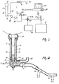
- a milking plant 1 for an implement for milking an animal automatically is depicted, with the representation of this milking plant being limited to only one teat cup 2 and one milk meter 3, for the sake of simplicity.
- the milk obtained from each udder quarter by means of teat cups 2 can be fed through a separate milk line 4 to a milk measuring apparatus comprising four milk meters 3.
- Separate discharge lines 5 of the milk meters 3 are connected to a common output line 7 running to a milk tank 6.
- a more elaborate basic set-up of the milking plant is depicted and described in EP-A-0 385 539.
- the milking plant further comprises, as far as matters are of importance to the present invention, a pulsator system 8 for the four teat cups 2.
- Vacuum line 9 for the pulsator system 8 is connected to a vacuum pump with equalizer tank, as is described in said European Patent Application.
- a longtitudinal section of a teat cup 2 is shown; as is usual, the teat cup has been built up from a rigid, e.g. metal, sleeve 10, from an inner wall 11 made of a flexible material, such as rubber, located in this sleeve, and from a rubber cap 13 which closes off the top side of gap 12 between the sleeve 10 and the inner wall 11.
- the bottom side of the gap between the sleeve 10 and the inner wall 11 is closed by a sealing ring 14, whilst between the sleeve 10 and the inner wall, above said ring, there is provided a ring 15 having an opening 16.
- the line 4 serving to drain the milk to the milk meter 3 is connected to this buffer space 19. Furthermore, in this buffer space 19 there is provided a stationary member 21 which partially projects into the opening between inner space 22 and the buffer space 19 to ensure that the milk gradually flows into buffer space 19 and any separation of the milk is prevented. On the top side of this member 21 there is provided a temperature-sensitive sensor 23 to make temperature measurements.
- the milk temperature as may thus be established already in the teat cup 2, is a good measure of the body temperature; especially the body temperatures of ill animals, such as those affected by mastitis, are beyond the normal value.
- a flow-sensitive sensor 24 to establish the starting and stopping of the milk flow is included in a falling portion of the milk line 4.
- the operation of this flow-sensitive sensor is based on that a flow of milk makes an electrical connection between two electrodes.
- the inclined position of the sensor prevents milk from being left in between the electrodes, or to put it differently, it prevents that a little pool of milk remains in between the electrodes; for this would result in that a flow of milk is indicated uninterruptedly.
- the milk line 4 also includes a vacuum-sensitive sensor 26 to establish whether a sufficient vacuum prevails in the milk line 4 and the teat cup 2.
- a sensor to determine the electrical conductivity 25 this is the mastitis sensor.
- This mastitis sensor comprises a reservoir provided with electrodes to measure the electrical conductivity of milk being in the reservoir. With each new flow of milk, the milk being in the reservoir is replaced.
- the output signals S1, S2, S3 and S4 of the respective sensors 23, 24, 25 and 26 are applied to a computer 27, where the information from these sensors is further processed and made knowable on the display screen of a monitor 28.
- the discharge line 5 is further provided with a three-way valve 29 to be able to drain the flow of milk from a quarter of the animal's udder affected by mastitis off into a waste tank 30.
Landscapes
- Life Sciences & Earth Sciences (AREA)
- Animal Husbandry (AREA)
- Environmental Sciences (AREA)
- Health & Medical Sciences (AREA)
- Zoology (AREA)
- Veterinary Medicine (AREA)
- Animal Behavior & Ethology (AREA)
- Pregnancy & Childbirth (AREA)
- Engineering & Computer Science (AREA)
- Biodiversity & Conservation Biology (AREA)
- Wood Science & Technology (AREA)
- Birds (AREA)
- General Health & Medical Sciences (AREA)
- Public Health (AREA)
- Biophysics (AREA)
- Farming Of Fish And Shellfish (AREA)
- Dairy Products (AREA)
- Catching Or Destruction (AREA)
- Feed For Specific Animals (AREA)
- Measuring Volume Flow (AREA)
- Housing For Livestock And Birds (AREA)
- External Artificial Organs (AREA)
- Feeding And Watering For Cattle Raising And Animal Husbandry (AREA)
- Investigating Or Analyzing Materials By The Use Of Electric Means (AREA)
- Management, Administration, Business Operations System, And Electronic Commerce (AREA)
Abstract
Description
Claims (14)
- A method of automatically milking animals, such as cows, in an implement with a milking plant including a computer and a milking robot with teat cups which are automatically connectable to the teats of an animal to be milked, in which method by means of a flow-sensitive sensor signals are produced indicating the beginning and the end of the milk flow from at least one teat, characterized by determining in the computer the dead time between the instant when a vacuum-sensitive sensor has determined a sufficient vacuum in a teat cup applied to a relevant teat and the instant when the start of a flow of milk from this teat has been determined by the flow sensitive sensor, whereafter, when in the computer it is established that the dead time exceeds a predetermined period of time as well as upon the production of the signal indicating the end of the milk flow from said teat, the teat cup is automatically put out of operation.
- A method as claimed in claim 1, characterized in that the dead time for the flow of milk from each of the teats is determined.
- A method as claimed in claim 1 or 2, characterized in that the extent to which the dead time exceeds a predetermined value for a relevant animal is determined by means of the computer.
- A method as claimed in claim 2, characterized in that the extent to which the dead time exceeds the predetermined value for each of the flows of milk from the respective teats is determined.
- A method as claimed in any one of the preceding claims, characterized in that the animal is led away from the location where automatic milking is intended to take place, when, after the creation of a vacuum in a teat cup, a particular time in relation to the dead time previously determined for the relevant animal has elapsed without the flow of milk in this cup having started.
- A method as claimed in any one of the preceding claims, characterized in that by means of the computer an indication of heat or illness of the animal is obtained from the dead time.
- A method as claimed in claim 6, characterized in that an indication of heat or illness of an animal is obtained from the dead time in combination with the temperature of the flow of milk established by a temperature sensor.
- A method as claimed in claim 6 or 7, characterized in that an indication of heat or illness of an animal is obtained from the dead time in combination with the electrical conductivity of the flow of milk established by a milk-conductivity sensor.
- A method as claimed in any one of claims 6 to 8, characterized in that, at randomly selectable times, the monitor display of the computer and/or a printer is capable of indicating the animals of which the dead time and/or the electrical conductivity and/or the temperature of a flow of milk have/has exceeded the respective predetermined values.
- A method as claimed in claim 9, characterized in that on the basis of the information on the electrical conductivity of a flow of milk given by the computer, it is decided on whether the milk produced by a relevant animal has to be drained off, e.g. into a waste tank, or not.
- An implement for automatically milking animals, such as cows, with a milking plant (1) including a computer (27) and a milking robot with teat cups (2) which are automatically connectable to the teats of an animal to be milked, the implement further comprising a flow-sensitive sensor (24) for producing signals indicating the beginning and the end of the flow of milk from at least one teat, characterized in that, the implement is provided with a vacuum-sensitive sensor (26) and the computer (27) is arranged to determine in response to signals from the flow-sensitive sensor (24) and the vacuum-sensitive sensor (26) the dead time between the instant when the vacuum-sensitive sensor has determined the existence of a sufficient vacuum in a teat-cup connected to a teat and the instant when the flow of milk from this teat has started and to determine if said dead time exceeds a predetermined period of time, in which case, as well as upon the production of a signal indicating the end of the milk flow from that teat, the teat cup is put out of operation automatically by means of the computer (27).
- An implement as claimed in claim 11, characterized in that by means of the computer (27) an indication of heat or illness of the animal is obtainable from the dead time.
- An implement as claimed in claim 12, characterized in that there is provided a temperature-sensitive sensor (23) for establishing the temperature of the relevant flow of milk, whilst by means of the computer (27) an indication of heat or illness of an animal is obtainable from the dead time in combination with the information stemming from the temperature-sensitive sensor (23).
- An implement as claimed in claim 12 or 13, characterized in that there is provided a sensor (25) for establishing the electrical conductivity of the milk, whilst by means of the computer (27) an indication of heat or illness of an animal is obtainable from the dead time in combination with the information stemming from the electrical-conductivity sensor (25).
Priority Applications (1)
| Application Number | Priority Date | Filing Date | Title |
|---|---|---|---|
| EP97203807A EP0836802B1 (en) | 1991-09-27 | 1992-09-24 | A method of and an implement for milking animals automatically |
Applications Claiming Priority (2)
| Application Number | Priority Date | Filing Date | Title |
|---|---|---|---|
| NL9101636 | 1991-09-25 | ||
| NL9101636A NL9101636A (en) | 1991-09-27 | 1991-09-27 | METHOD FOR AUTOMATIC MILKING OF ANIMALS. |
Related Child Applications (1)
| Application Number | Title | Priority Date | Filing Date |
|---|---|---|---|
| EP97203807A Division EP0836802B1 (en) | 1991-09-27 | 1992-09-24 | A method of and an implement for milking animals automatically |
Publications (3)
| Publication Number | Publication Date |
|---|---|
| EP0534565A2 EP0534565A2 (en) | 1993-03-31 |
| EP0534565A3 EP0534565A3 (en) | 1993-12-01 |
| EP0534565B1 true EP0534565B1 (en) | 1998-09-09 |
Family
ID=19859755
Family Applications (3)
| Application Number | Title | Priority Date | Filing Date |
|---|---|---|---|
| EP92202939A Revoked EP0534565B1 (en) | 1991-09-27 | 1992-09-24 | An implement for and a method of milking animals automatically |
| EP97203807A Revoked EP0836802B1 (en) | 1991-09-27 | 1992-09-24 | A method of and an implement for milking animals automatically |
| EP92202935A Expired - Lifetime EP0534564B2 (en) | 1991-09-27 | 1992-09-24 | An implement for milking animals automatically |
Family Applications After (2)
| Application Number | Title | Priority Date | Filing Date |
|---|---|---|---|
| EP97203807A Revoked EP0836802B1 (en) | 1991-09-27 | 1992-09-24 | A method of and an implement for milking animals automatically |
| EP92202935A Expired - Lifetime EP0534564B2 (en) | 1991-09-27 | 1992-09-24 | An implement for milking animals automatically |
Country Status (7)
| Country | Link |
|---|---|
| EP (3) | EP0534565B1 (en) |
| JP (1) | JP3317968B2 (en) |
| AT (3) | ATE204426T1 (en) |
| DE (6) | DE69224692T3 (en) |
| DK (3) | DK0534564T4 (en) |
| NL (1) | NL9101636A (en) |
| WO (1) | WO1993005647A2 (en) |
Cited By (2)
| Publication number | Priority date | Publication date | Assignee | Title |
|---|---|---|---|---|
| EP1279326B2 (en) † | 2001-07-25 | 2014-06-11 | Lely Enterprises AG | A method of automatically milking a dairy animal |
| DE102017120656A1 (en) | 2017-09-07 | 2019-03-07 | Gea Farm Technologies Gmbh | Method for reducing the individual milk production of dairy animals |
Families Citing this family (37)
| Publication number | Priority date | Publication date | Assignee | Title |
|---|---|---|---|---|
| NL9300143A (en) | 1993-01-26 | 1994-08-16 | Lely Nv C Van Der | Milking machine. |
| NL9400131A (en) * | 1994-01-28 | 1995-09-01 | Maasland Nv | Device for milking animals. |
| NL9400132A (en) * | 1994-01-28 | 1995-09-01 | Maasland Nv | Device for milking animals. |
| NL9500362A (en) * | 1994-04-14 | 1995-11-01 | Maasland Nv | Method for automatic milking of animals and device in which this method can be applied. |
| AU724419B2 (en) * | 1994-04-27 | 2000-09-21 | Maasland N.V. | A method of automatically milking animals and an implement for applying same |
| NL9401937A (en) * | 1994-04-27 | 1995-12-01 | Maasland Nv | Method for automatic milking of animals and device in which this method can be applied. |
| NL9401942A (en) * | 1994-11-22 | 1996-07-01 | Maasland Nv | Method for automatic milking of animals and device for applying this method. |
| DE29522436U1 (en) * | 1994-12-09 | 2004-03-11 | Maasland N.V. | Line system for the teat cup of a milking machine |
| SE9404539D0 (en) * | 1994-12-28 | 1994-12-28 | Tetra Laval Holdings & Finance | Apparatus and method for monitoring animals |
| NL1001158C2 (en) * | 1995-09-08 | 1997-03-11 | Maasland Nv | Method for cleaning a milk line system. |
| NL1001646C2 (en) * | 1995-11-14 | 1997-05-21 | Maasland Nv | Construction with a device for milking animals. |
| EP0801893B1 (en) * | 1996-04-17 | 2002-09-18 | Maasland N.V. | A machine for milking animals, such as cows |
| DE19630146C2 (en) * | 1996-07-25 | 1998-06-10 | Jakob Maier | Device for automatic milk separation |
| NL1007140C2 (en) * | 1997-09-26 | 1999-03-29 | Idento Electronics Bv | Milking installation. |
| NL1008671C2 (en) * | 1998-03-23 | 1999-09-24 | Maasland Nv | Milking organ. |
| NL1008672C2 (en) * | 1998-03-23 | 1999-09-24 | Maasland Nv | Method and device for milking and / or caring for animals. |
| SE519708C2 (en) * | 1998-07-31 | 2003-04-01 | Delaval Holding Ab | Device and method for detecting a disease of the udder of an animal |
| FR2782600B1 (en) | 1998-08-27 | 2000-11-17 | Lorraine Inst Nat Polytech | METHOD AND SYSTEM FOR MONITORING THE HEALTH CONDITION OF THE Udder AND FOR ASSESSING THE PHYSICO-CHEMICAL QUALITY OF MILK |
| SE514037C2 (en) * | 1998-08-31 | 2000-12-18 | Delaval Holding Ab | Method and apparatus for cleaning the teats of a dairy animal's udder |
| WO2000018218A1 (en) * | 1998-09-28 | 2000-04-06 | Babson Bros. Co. | Milk flow monitor and milker unit detacher |
| ATE251749T1 (en) * | 1999-06-09 | 2003-10-15 | Agres Ltd | METHOD FOR DETECTING MASTITIS |
| NL1012529C2 (en) * | 1999-07-07 | 2001-01-09 | Lely Res Holding | Device for milking animals, such as cows. |
| DE19953700C2 (en) * | 1999-11-08 | 2002-11-28 | Ifu Gmbh | Device for determining the state of health of an animal udder |
| NL1014780C2 (en) * | 2000-03-29 | 2001-02-20 | Idento Electronics Bv | Method and device for milking livestock. |
| FR2814335B1 (en) * | 2000-09-28 | 2004-08-13 | Georges Fritz | METHOD AND DEVICE FOR IN VITRO DIAGNOSIS OF A MAMMITE |
| DE10129475B4 (en) * | 2001-06-21 | 2016-11-10 | Gea Farm Technologies Gmbh | Method for milking an animal, in particular a cow |
| NL1018649C2 (en) * | 2001-07-27 | 2003-01-28 | Lely Entpr Ag | Device and method for milking an animal, and device for cleaning a teat and / or quarter of an animal. |
| DE10257735A1 (en) | 2002-12-10 | 2004-06-24 | Westfaliasurge Gmbh | Method of milking an animal and a milking parlor |
| SE525789C2 (en) * | 2003-07-17 | 2005-04-26 | Delaval Holding Ab | Method and apparatus for indicating a state of health of a dairy animal |
| DE102004033637B4 (en) | 2004-03-23 | 2012-07-26 | Wilfried Hatzack | Holding device for milking cup with a drive for generating a movement |
| DE102005026877A1 (en) * | 2005-06-10 | 2006-12-28 | Westfaliasurge Gmbh | Method and device for determining information about an animal and / or animal milk |
| US7926449B2 (en) | 2007-06-25 | 2011-04-19 | Delaval Holding Ab | Fluid application systems and methods and milking systems and methods |
| CL2009000437A1 (en) | 2009-02-26 | 2009-09-04 | Valenzuela Ronnie Uslar | Automatic independent liner removal system which, when incorporated into any conventional milking equipment, automatically discriminates when the milk contained in each mammary glandular room is finished, comprises in each short hose each nipple is a discrete and empty flow sensor, interconnected to a controller. |
| WO2011032901A2 (en) * | 2009-09-18 | 2011-03-24 | Delaval Holding Ab | An arrangement and a method for attaching at least one teat cup to a teat of an animal by means of a robot arm |
| US9545077B2 (en) | 2011-12-16 | 2017-01-17 | Delaval Holding Ab | Milking system and a method for preventing detachment of a teat cup from a teat during a milking process |
| US20220095577A1 (en) * | 2019-06-19 | 2022-03-31 | Lakto Hayvancilik Teknolojileri Sanayi Ve Ticaret Limited Sirketi | Free flow electronic meter |
| EP4037475B1 (en) | 2019-09-30 | 2025-01-08 | DeLaval Holding AB | An automatic milking system and a method of determining a health condition of an animal |
Citations (1)
| Publication number | Priority date | Publication date | Assignee | Title |
|---|---|---|---|---|
| US3874337A (en) * | 1973-07-30 | 1975-04-01 | Raymond E Umbaugh | Temperature responsive system for milking apparatus |
Family Cites Families (13)
| Publication number | Priority date | Publication date | Assignee | Title |
|---|---|---|---|---|
| GB1383038A (en) * | 1972-09-12 | 1975-02-05 | Babson Bros Co | Milking apparatus |
| CS183854B1 (en) † | 1975-04-29 | 1978-07-31 | Ladislav Mukarovsky | Equipment for automatic checking and control of milking process |
| US4185414A (en) * | 1977-11-07 | 1980-01-29 | General Electric Company | Feed regulator for nutrient film agriculture system |
| US4516530A (en) * | 1983-10-14 | 1985-05-14 | Germania Dairy Automation, Inc. | Milk sweep method and apparatus for automated milking systems |
| US4941433A (en) * | 1988-05-23 | 1990-07-17 | Agri-Automation Company, Ltd. | Milking method and related apparatus |
| US4922855A (en) * | 1988-05-24 | 1990-05-08 | Orion Machinery Co., Ltd. | Milking machine |
| NL8802332A (en) * | 1988-09-21 | 1990-04-17 | Lely Nv C Van Der | APPARATUS FOR MILKING AN ANIMAL. |
| GB8900084D0 (en) * | 1989-01-04 | 1989-03-01 | British Res Agricult Eng | Milking |
| NL193553C (en) * | 1989-02-27 | 2003-01-10 | Lely Entpr Ag | Milking installation. |
| DE3935759A1 (en) * | 1989-10-27 | 1991-05-02 | Lang Apparatebau Gmbh | DEVICE AND METHOD FOR MEASURING THE ELECTRICAL CONDUCTIVITY OF MILK |
| NL9001689A (en) * | 1990-02-23 | 1991-09-16 | Lely Nv C Van Der | Milking plant for cow herd - has milk conductivity sensor arranged in measuring chamber of milk meter, and milk level sensor which applies control signal to computer |
| DE4007327C1 (en) * | 1990-03-08 | 1991-07-11 | Lang Apparatebau Gmbh, 8227 Siegsdorf, De | |
| JP6146091B2 (en) | 2013-03-29 | 2017-06-14 | 凸版印刷株式会社 | Lid material |
-
1991
- 1991-09-27 NL NL9101636A patent/NL9101636A/en not_active Application Discontinuation
-
1992
- 1992-09-24 JP JP50597593A patent/JP3317968B2/en not_active Expired - Fee Related
- 1992-09-24 DE DE69224692T patent/DE69224692T3/en not_active Expired - Lifetime
- 1992-09-24 DE DE9219130U patent/DE9219130U1/en not_active Expired - Lifetime
- 1992-09-24 EP EP92202939A patent/EP0534565B1/en not_active Revoked
- 1992-09-24 AT AT97203807T patent/ATE204426T1/en not_active IP Right Cessation
- 1992-09-24 DE DE4293408T patent/DE4293408T1/en not_active Withdrawn
- 1992-09-24 DE DE69226918T patent/DE69226918T2/en not_active Revoked
- 1992-09-24 DK DK92202935T patent/DK0534564T4/en active
- 1992-09-24 EP EP97203807A patent/EP0836802B1/en not_active Revoked
- 1992-09-24 DE DE4293408A patent/DE4293408B4/en not_active Expired - Lifetime
- 1992-09-24 DE DE69232021T patent/DE69232021T2/en not_active Expired - Lifetime
- 1992-09-24 EP EP92202935A patent/EP0534564B2/en not_active Expired - Lifetime
- 1992-09-24 AT AT92202939T patent/ATE170704T1/en not_active IP Right Cessation
- 1992-09-24 DK DK92202939T patent/DK0534565T3/en active
- 1992-09-24 DK DK97203807T patent/DK0836802T3/en active
- 1992-09-24 AT AT92202935T patent/ATE163833T1/en not_active IP Right Cessation
- 1992-09-24 WO PCT/NL1992/000162 patent/WO1993005647A2/en not_active Ceased
Patent Citations (1)
| Publication number | Priority date | Publication date | Assignee | Title |
|---|---|---|---|---|
| US3874337A (en) * | 1973-07-30 | 1975-04-01 | Raymond E Umbaugh | Temperature responsive system for milking apparatus |
Cited By (4)
| Publication number | Priority date | Publication date | Assignee | Title |
|---|---|---|---|---|
| EP1279326B2 (en) † | 2001-07-25 | 2014-06-11 | Lely Enterprises AG | A method of automatically milking a dairy animal |
| DE102017120656A1 (en) | 2017-09-07 | 2019-03-07 | Gea Farm Technologies Gmbh | Method for reducing the individual milk production of dairy animals |
| WO2019048521A1 (en) | 2017-09-07 | 2019-03-14 | Gea Farm Technologies Gmbh | METHOD FOR REDUCING ANIMAL INDIVIDUAL MILK PRODUCTION OF DAIRY ANIMALS |
| US11659809B2 (en) | 2017-09-07 | 2023-05-30 | Gea Farm Technologies Gmbh | Method for reducing the individual-specific milk production of milk-producing animals |
Also Published As
| Publication number | Publication date |
|---|---|
| EP0534565A2 (en) | 1993-03-31 |
| NL9101636A (en) | 1993-04-16 |
| DE4293408B4 (en) | 2004-01-29 |
| EP0836802A2 (en) | 1998-04-22 |
| DK0836802T3 (en) | 2001-11-26 |
| JP3317968B2 (en) | 2002-08-26 |
| ATE204426T1 (en) | 2001-09-15 |
| JPH06504204A (en) | 1994-05-19 |
| DE69224692D1 (en) | 1998-04-16 |
| DE69232021D1 (en) | 2001-09-27 |
| EP0836802A3 (en) | 1998-08-19 |
| DE69232021T2 (en) | 2002-04-18 |
| DE4293408T1 (en) | 1996-03-07 |
| WO1993005647A3 (en) | 1993-05-13 |
| EP0534564B1 (en) | 1998-03-11 |
| WO1993005647A2 (en) | 1993-04-01 |
| EP0534565A3 (en) | 1993-12-01 |
| EP0534564A3 (en) | 1993-08-11 |
| DK0534564T3 (en) | 1998-11-30 |
| ATE170704T1 (en) | 1998-09-15 |
| DE9219130U1 (en) | 1998-04-16 |
| EP0836802B1 (en) | 2001-08-22 |
| EP0534564A2 (en) | 1993-03-31 |
| DE69224692T3 (en) | 2006-07-20 |
| DE69224692T2 (en) | 1998-08-27 |
| DE69226918D1 (en) | 1998-10-15 |
| EP0534564B2 (en) | 2005-11-09 |
| DK0534565T3 (en) | 1999-06-07 |
| DK0534564T4 (en) | 2006-03-20 |
| DE69226918T2 (en) | 1999-03-18 |
| ATE163833T1 (en) | 1998-03-15 |
Similar Documents
| Publication | Publication Date | Title |
|---|---|---|
| EP0534565B1 (en) | An implement for and a method of milking animals automatically | |
| US5568788A (en) | Implement for and a method of milking animals automatically | |
| US5704311A (en) | Method and apparatus for automatically milking animals | |
| EP0510779B1 (en) | A milking plant | |
| US7174848B2 (en) | Controller for monitoring and controlling pulsators in a milking system | |
| EP0713641B1 (en) | A method of automatically milking animals and an implement for applying same | |
| EP1297742B1 (en) | A method of collecting measurement data during automatically milking an animal | |
| EP1297744B1 (en) | A method of separating milk from dairy animals | |
| EP0468588A1 (en) | An implement for automatically milking an animal | |
| EP1297741B1 (en) | A device for milking animals | |
| EP1297743A2 (en) | A device for separating milk from a dairy animal | |
| EP1279329A2 (en) | A device for and a method of milking an animal and a device for cleaning a teat and/or an udder quarter of an animal |
Legal Events
| Date | Code | Title | Description |
|---|---|---|---|
| PUAI | Public reference made under article 153(3) epc to a published international application that has entered the european phase |
Free format text: ORIGINAL CODE: 0009012 |
|
| AK | Designated contracting states |
Kind code of ref document: A2 Designated state(s): AT BE CH DE DK FR GB IT LI NL SE |
|
| PUAL | Search report despatched |
Free format text: ORIGINAL CODE: 0009013 |
|
| AK | Designated contracting states |
Kind code of ref document: A3 Designated state(s): AT BE CH DE DK FR GB IT LI NL SE |
|
| 17P | Request for examination filed |
Effective date: 19940509 |
|
| 17Q | First examination report despatched |
Effective date: 19950817 |
|
| GRAG | Despatch of communication of intention to grant |
Free format text: ORIGINAL CODE: EPIDOS AGRA |
|
| GRAG | Despatch of communication of intention to grant |
Free format text: ORIGINAL CODE: EPIDOS AGRA |
|
| GRAH | Despatch of communication of intention to grant a patent |
Free format text: ORIGINAL CODE: EPIDOS IGRA |
|
| RAP1 | Party data changed (applicant data changed or rights of an application transferred) |
Owner name: MAASLAND N.V. |
|
| GRAH | Despatch of communication of intention to grant a patent |
Free format text: ORIGINAL CODE: EPIDOS IGRA |
|
| GRAA | (expected) grant |
Free format text: ORIGINAL CODE: 0009210 |
|
| AK | Designated contracting states |
Kind code of ref document: B1 Designated state(s): AT BE CH DE DK FR GB IT LI NL SE |
|
| REF | Corresponds to: |
Ref document number: 170704 Country of ref document: AT Date of ref document: 19980915 Kind code of ref document: T |
|
| REG | Reference to a national code |
Ref country code: CH Ref legal event code: EP |
|
| REF | Corresponds to: |
Ref document number: 69226918 Country of ref document: DE Date of ref document: 19981015 |
|
| REG | Reference to a national code |
Ref country code: CH Ref legal event code: NV Representative=s name: PATENTANWALTSBUERO EDER AG |
|
| ET | Fr: translation filed | ||
| REG | Reference to a national code |
Ref country code: DK Ref legal event code: T3 |
|
| PLBQ | Unpublished change to opponent data |
Free format text: ORIGINAL CODE: EPIDOS OPPO |
|
| PLBI | Opposition filed |
Free format text: ORIGINAL CODE: 0009260 |
|
| PLBQ | Unpublished change to opponent data |
Free format text: ORIGINAL CODE: EPIDOS OPPO |
|
| PLBI | Opposition filed |
Free format text: ORIGINAL CODE: 0009260 |
|
| PLBF | Reply of patent proprietor to notice(s) of opposition |
Free format text: ORIGINAL CODE: EPIDOS OBSO |
|
| 26 | Opposition filed |
Opponent name: ALFA LAVAL AGRI AB Effective date: 19990608 |
|
| 26 | Opposition filed |
Opponent name: PROLION B.V. Effective date: 19990609 Opponent name: ALFA LAVAL AGRI AB Effective date: 19990608 |
|
| PLBF | Reply of patent proprietor to notice(s) of opposition |
Free format text: ORIGINAL CODE: EPIDOS OBSO |
|
| PLBF | Reply of patent proprietor to notice(s) of opposition |
Free format text: ORIGINAL CODE: EPIDOS OBSO |
|
| PLBF | Reply of patent proprietor to notice(s) of opposition |
Free format text: ORIGINAL CODE: EPIDOS OBSO |
|
| PGFP | Annual fee paid to national office [announced via postgrant information from national office to epo] |
Ref country code: FR Payment date: 20000901 Year of fee payment: 9 |
|
| PGFP | Annual fee paid to national office [announced via postgrant information from national office to epo] |
Ref country code: CH Payment date: 20000904 Year of fee payment: 9 |
|
| PGFP | Annual fee paid to national office [announced via postgrant information from national office to epo] |
Ref country code: SE Payment date: 20000905 Year of fee payment: 9 Ref country code: GB Payment date: 20000905 Year of fee payment: 9 Ref country code: DK Payment date: 20000905 Year of fee payment: 9 Ref country code: DE Payment date: 20000905 Year of fee payment: 9 |
|
| PGFP | Annual fee paid to national office [announced via postgrant information from national office to epo] |
Ref country code: AT Payment date: 20000906 Year of fee payment: 9 |
|
| PGFP | Annual fee paid to national office [announced via postgrant information from national office to epo] |
Ref country code: NL Payment date: 20000920 Year of fee payment: 9 |
|
| PGFP | Annual fee paid to national office [announced via postgrant information from national office to epo] |
Ref country code: BE Payment date: 20001004 Year of fee payment: 9 |
|
| RDAH | Patent revoked |
Free format text: ORIGINAL CODE: EPIDOS REVO |
|
| RDAG | Patent revoked |
Free format text: ORIGINAL CODE: 0009271 |
|
| 27W | Patent revoked |
Effective date: 20010213 |
|
| GBPR | Gb: patent revoked under art. 102 of the ep convention designating the uk as contracting state |
Free format text: 20010213 |
|
| REG | Reference to a national code |
Ref country code: CH Ref legal event code: PL |
|
| NLR2 | Nl: decision of opposition |