EP0533644A2 - Breathing circuit and heat and moisture exchanger therefor - Google Patents
Breathing circuit and heat and moisture exchanger therefor Download PDFInfo
- Publication number
- EP0533644A2 EP0533644A2 EP92850221A EP92850221A EP0533644A2 EP 0533644 A2 EP0533644 A2 EP 0533644A2 EP 92850221 A EP92850221 A EP 92850221A EP 92850221 A EP92850221 A EP 92850221A EP 0533644 A2 EP0533644 A2 EP 0533644A2
- Authority
- EP
- European Patent Office
- Prior art keywords
- heat
- moisture
- patient
- respirator
- exchanger
- Prior art date
- Legal status (The legal status is an assumption and is not a legal conclusion. Google has not performed a legal analysis and makes no representation as to the accuracy of the status listed.)
- Granted
Links
Images
Classifications
-
- A—HUMAN NECESSITIES
- A61—MEDICAL OR VETERINARY SCIENCE; HYGIENE
- A61M—DEVICES FOR INTRODUCING MEDIA INTO, OR ONTO, THE BODY; DEVICES FOR TRANSDUCING BODY MEDIA OR FOR TAKING MEDIA FROM THE BODY; DEVICES FOR PRODUCING OR ENDING SLEEP OR STUPOR
- A61M16/00—Devices for influencing the respiratory system of patients by gas treatment, e.g. mouth-to-mouth respiration; Tracheal tubes
- A61M16/10—Preparation of respiratory gases or vapours
- A61M16/1045—Devices for humidifying or heating the inspired gas by using recovered moisture or heat from the expired gas
-
- A—HUMAN NECESSITIES
- A61—MEDICAL OR VETERINARY SCIENCE; HYGIENE
- A61M—DEVICES FOR INTRODUCING MEDIA INTO, OR ONTO, THE BODY; DEVICES FOR TRANSDUCING BODY MEDIA OR FOR TAKING MEDIA FROM THE BODY; DEVICES FOR PRODUCING OR ENDING SLEEP OR STUPOR
- A61M16/00—Devices for influencing the respiratory system of patients by gas treatment, e.g. mouth-to-mouth respiration; Tracheal tubes
- A61M16/08—Bellows; Connecting tubes ; Water traps; Patient circuits
- A61M16/0816—Joints or connectors
- A61M16/0833—T- or Y-type connectors, e.g. Y-piece
-
- A—HUMAN NECESSITIES
- A61—MEDICAL OR VETERINARY SCIENCE; HYGIENE
- A61M—DEVICES FOR INTRODUCING MEDIA INTO, OR ONTO, THE BODY; DEVICES FOR TRANSDUCING BODY MEDIA OR FOR TAKING MEDIA FROM THE BODY; DEVICES FOR PRODUCING OR ENDING SLEEP OR STUPOR
- A61M16/00—Devices for influencing the respiratory system of patients by gas treatment, e.g. mouth-to-mouth respiration; Tracheal tubes
- A61M16/10—Preparation of respiratory gases or vapours
- A61M16/105—Filters
- A61M16/1055—Filters bacterial
-
- A—HUMAN NECESSITIES
- A61—MEDICAL OR VETERINARY SCIENCE; HYGIENE
- A61M—DEVICES FOR INTRODUCING MEDIA INTO, OR ONTO, THE BODY; DEVICES FOR TRANSDUCING BODY MEDIA OR FOR TAKING MEDIA FROM THE BODY; DEVICES FOR PRODUCING OR ENDING SLEEP OR STUPOR
- A61M16/00—Devices for influencing the respiratory system of patients by gas treatment, e.g. mouth-to-mouth respiration; Tracheal tubes
- A61M16/10—Preparation of respiratory gases or vapours
- A61M16/105—Filters
- A61M16/106—Filters in a path
- A61M16/1065—Filters in a path in the expiratory path
Definitions
- the present invention relates to an arrangement for connecting a patient to a respirator which is provided with inlet and outlet for gas expired and inspired by the patient, and also to the use of a moisture-heat-exchanger in said arrangement.
- a patient connected to a respirator inspires moist air which, via a humidifier, is fed out from the respirator, and expires moist air, which is introduced into the respirator. Due to the humidifier, the expired air has a considerable moisture content and condenses within the respirator and therewith contaminates the respirator, therewith necessitating, among other things, cleaning and sterilization of the respirator at regular intervals.
- the moist air is also liable to have a negative influence on these components and is liable to result in damage to those which come into contact with condensation, or during the sterilization process.
- a filter has been coupled between the patient and the respirator inlet, in which bacteria and moisture collect, this moisture condensing in the filter container.
- the resistance to flow through the filter container becomes so great as to necessitate removal of the filter container, which is then discarded and replaced with a new container and filter. If this procedure is not followed, the safety of the patient is jeopardized. It is often necessary to change the filter and container three to four times each day, which is both time-consuming and expensive, since containers and filters of this kind demand a relatively high price.
- An object of the present invention is to avoid the drawbacks associated with the aforedescribed arrangements and to provide an arrangement which obviates the use of the aforesaid filter or with which it is only necessary to replace the filter after long periods of use.
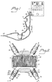
- Figure 1 is a schematic view of the inventive arrangement and shows the arrangement coupled between a patient and a respirator; and Figure 2 is a sectional view through the arrangement illustrated in Figure 1.
- Figure 1 illustrates a conventional respirator 1 which is provided with an inlet 2 and an outlet 3.
- the respirator 1 is connected to a patient (not shown) by means of hoses 4, 5, 6a, 6b, 7a and 7b, and an active air humidifier 8, a bacteria filter 9, the inventive arrangement, referenced 10, and a Y-piece 22.
- the respirator outlet 3 for expiration gases is connected, by means of the hose 4, to the arrangement 10 which is connected to the Y-piece 22 via the hose 6b, the active air humidifier 8 and the hose 6a.
- the Y-piece 22 is connected to the patient in a conventional manner.
- the Y-piece 11 is connected to the arrangement 10 through the intermediary of the hose 5, and the arrangement 10 is connected to the respirator inlet 2 through the intermediary of the hose 8a, the bacteria filter 9 and the hose 7b.
- the air humidifier 8 is a conventional, active air humidifier which contains an electrically heated water bath through which the gas is forced to pass before being administered to the patient.
- the bacteria filter 9 is also of a conventional kind and is comprised of a container with a filter constructed from siliconized glass fibre. The bacteria filter 9 is not essential to the function of the inventive arrangement and can therefore be omitted.
- the arrangement 10 includes a casing or housing which is comprised of two parts 11 and 12 and which has a substantially circular-cylindrical shape with ends in the form of truncated cones.
- the parts 11 and 12 are detachably screwed together on each side at 13.
- Removably placed in a circular-cylindrical cavity in the housing 11, 12 is a moisture-heat-exchanger element 14 which is of the kind used in conventional moisture-heat-exchangers and which may also be comprised of one or more corrugated bands of heat-and-moisture absorbing and heat-and-moisture emitting paper material which is wound to cylinder form. Those channels in the element 14 through which gas and moisture pass and which.
- the element 14 substantially fills the whole of the cavity in the housing 11, 12.
- the element 14 may also be constructed so as to filter the gases, or may be supplemented with a filter part 21, which is mounted in the housing 11, 12 on the upper side (the illustrated side) of the element and/or on its underside.
- the arrangement 10 is made as small as possible, in order to minimize the amount of expiration gas collected, this gas containing carbon dioxide and liable to be returned to the patient in the inspiration phase of a breathing cycle.
- the housing parts 11 and 12 are provided with four, preferably identical connectors 15, 16, 17 and 18 to which the hoses 4, 5, 6b and 7a are detachably connected.
- the connector 15 is connected to the hose 4, the connector 16 to the hose 5, the connector 17 to the hose 6b and the connector 18 to the hose 7a, as illustrated in Figure 1.
- Each connector 15-18 is comprised of an inner part which is firmly fixed to the housing 11, 12 and an outer part which is screwed firmly onto the inner part.
- Check valves 19 and 20 are mounted in respective connectors 16 and 17.
- Each check valve 19, 20 is comprised of a one-piece plastic element comprising a sleeve 19d and 20d respectively with a respective ring-shaped seat 19a and 20a, which are firmly clamped between the two connector parts, and a cap 19b and 20b respectively which is firmly connected to and normally seals (as shown) against the sleeve, through the intermediary of a plurality of respective spring legs 19c and 20c surrounding the sleeve.
- the cap 19b is located above the seat 19a, whereas in the connector 17 the cap 20b is located beneath the seat 20a, meaning that gas is allowed to pass through the connector 16 in the direction of the arrow A towards the arrangement 10 and that gas is permitted to pass through the connector 17 in the direction of the arrow B, by removing respective caps 19b and 20b from respective sleeves 19d and 20d. Respective caps 19b and 20b are pressed against respective sleeves 19d and 20d, so as to prevent gas from passing in the opposite directions.
- the connectors 15-18 communicate with the cavity in which the element 14 is inserted, through holes in the walls of the housing 11, 12.
- gas is discharged from the respirator outlet 3 during the gas inspiration cycle of the patient and exits through the connector 15 in the arrangement 10. Subsequent to the gas having passed through the element 14, and entraining moisture therefrom, the gas enters the connector 17 and is then delivered to the patient via the open check valve 20 and then through the humidifier 8. In this phase, the check valve 19b prevents gas from entering the connector 16. Since the respirator inlet 2 is blocked within the respirator, no appreciable amount of gas will pass through the connector 18.
- expiration gas is delivered through the connector 16. Subsequent to the gas having passed the same parts of the element 14, which earlier have been passed by the inspiration gas, the dehumidified gas enters the connector 18 and is passed further to the patient, via the bacteria filter 9.
- the check valve 20 therewith prevents gas from being drawn in through the connector 17 from the humidifier 8 to the filter 14.
- the outlet 3 is closed within the respirator 1 during the expiration cycle, and consequently no gas is passed out through the connector 15.
- the aforedescribed arrangement can be modified without departing from the inventive concept.
Abstract
Description
- The present invention relates to an arrangement for connecting a patient to a respirator which is provided with inlet and outlet for gas expired and inspired by the patient, and also to the use of a moisture-heat-exchanger in said arrangement.
- A patient connected to a respirator inspires moist air which, via a humidifier, is fed out from the respirator, and expires moist air, which is introduced into the respirator. Due to the humidifier, the expired air has a considerable moisture content and condenses within the respirator and therewith contaminates the respirator, therewith necessitating, among other things, cleaning and sterilization of the respirator at regular intervals. When using more modern types of respirator which include sensitive sensors, the moist air is also liable to have a negative influence on these components and is liable to result in damage to those which come into contact with condensation, or during the sterilization process.
- In order to solve the aforesaid problems, a filter has been coupled between the patient and the respirator inlet, in which bacteria and moisture collect, this moisture condensing in the filter container. When the container has been filled with a given volume of condensed water, the resistance to flow through the filter container becomes so great as to necessitate removal of the filter container, which is then discarded and replaced with a new container and filter. If this procedure is not followed, the safety of the patient is jeopardized. It is often necessary to change the filter and container three to four times each day, which is both time-consuming and expensive, since containers and filters of this kind demand a relatively high price.
- An object of the present invention is to avoid the drawbacks associated with the aforedescribed arrangements and to provide an arrangement which obviates the use of the aforesaid filter or with which it is only necessary to replace the filter after long periods of use.
- This object is fulfilled with an inventive arrangement having the features set forth in the characterizing clauses of respective Claims.
- Figure 1 is a schematic view of the inventive arrangement and shows the arrangement coupled between a patient and a respirator; and Figure 2 is a sectional view through the arrangement illustrated in Figure 1.
- Figure 1 illustrates a
conventional respirator 1 which is provided with aninlet 2 and an outlet 3. Therespirator 1 is connected to a patient (not shown) by means ofhoses active air humidifier 8, abacteria filter 9, the inventive arrangement, referenced 10, and a Y-piece 22. - The respirator outlet 3 for expiration gases is connected, by means of the hose 4, to the
arrangement 10 which is connected to the Y-piece 22 via thehose 6b, theactive air humidifier 8 and thehose 6a. The Y-piece 22 is connected to the patient in a conventional manner. The Y-piece 11 is connected to thearrangement 10 through the intermediary of thehose 5, and thearrangement 10 is connected to therespirator inlet 2 through the intermediary of the hose 8a, thebacteria filter 9 and thehose 7b. - Thus, the gases that are inspired by the patient pass through the
arrangement 10 and theair humidifier 8, whereas the gas expired by the patient passes through thearrangement 10 and thebacteria filter 9. - The
air humidifier 8 is a conventional, active air humidifier which contains an electrically heated water bath through which the gas is forced to pass before being administered to the patient. Thebacteria filter 9 is also of a conventional kind and is comprised of a container with a filter constructed from siliconized glass fibre. Thebacteria filter 9 is not essential to the function of the inventive arrangement and can therefore be omitted. - As shown more clearly in Figure 2, the
arrangement 10 includes a casing or housing which is comprised of twoparts parts housing exchanger element 14 which is of the kind used in conventional moisture-heat-exchangers and which may also be comprised of one or more corrugated bands of heat-and-moisture absorbing and heat-and-moisture emitting paper material which is wound to cylinder form. Those channels in theelement 14 through which gas and moisture pass and which. are formed between the band layers extend parallel with the centre axis of the cylinder. Theelement 14 substantially fills the whole of the cavity in thehousing element 14 may also be constructed so as to filter the gases, or may be supplemented with afilter part 21, which is mounted in thehousing arrangement 10 is made as small as possible, in order to minimize the amount of expiration gas collected, this gas containing carbon dioxide and liable to be returned to the patient in the inspiration phase of a breathing cycle. - The
housing parts identical connectors hoses connector 15 is connected to the hose 4, theconnector 16 to thehose 5, theconnector 17 to thehose 6b and theconnector 18 to thehose 7a, as illustrated in Figure 1. Each connector 15-18 is comprised of an inner part which is firmly fixed to thehousing Check valves respective connectors check valve sleeve shaped seat respective spring legs connector 16, the cap 19b is located above theseat 19a, whereas in theconnector 17 the cap 20b is located beneath theseat 20a, meaning that gas is allowed to pass through theconnector 16 in the direction of the arrow A towards thearrangement 10 and that gas is permitted to pass through theconnector 17 in the direction of the arrow B, by removing respective caps 19b and 20b fromrespective sleeves respective sleeves element 14 is inserted, through holes in the walls of thehousing - When using the inventive arrangement, as it is connected in Figure 1, gas is discharged from the respirator outlet 3 during the gas inspiration cycle of the patient and exits through the
connector 15 in thearrangement 10. Subsequent to the gas having passed through theelement 14, and entraining moisture therefrom, the gas enters theconnector 17 and is then delivered to the patient via theopen check valve 20 and then through thehumidifier 8. In this phase, the check valve 19b prevents gas from entering theconnector 16. Since therespirator inlet 2 is blocked within the respirator, no appreciable amount of gas will pass through theconnector 18. - During the expiration cycle of the patient, expiration gas is delivered through the
connector 16. Subsequent to the gas having passed the same parts of theelement 14, which earlier have been passed by the inspiration gas, the dehumidified gas enters theconnector 18 and is passed further to the patient, via thebacteria filter 9. Thecheck valve 20 therewith prevents gas from being drawn in through theconnector 17 from thehumidifier 8 to thefilter 14. The outlet 3 is closed within therespirator 1 during the expiration cycle, and consequently no gas is passed out through theconnector 15. - The aforedescribed arrangement can be modified without departing from the inventive concept. For example, it is possible to use only one of the
aforesaid check valves 19 20, and it is also possible to provide a total of only two connectors on thehousing inlet connectors outlet connectors hoses 4 and 7a through the intermediary of a T-piece or Y-piece, and the other connector is connected to thehoses housing hoses arrangement 10. When using T-pieces or Y-pieces, the check valves can be placed in said pieces instead of the connectors. - The invention is only restricted by the features set forth in the following Claims.
Claims (10)
- An arrangement for connecting a patient to a respirator (1), comprising a humidifier (8) for humidifying gas inspired by the patient, characterized in that it includes a moisture-heat-exchanger (10) whose one side is connected to the respirator inlet and outlet (2, 3) and whose other side is connected to the patient such that inspired gases pass the humidifier (8) before reaching the patient and expired gases do not pass the humidifier.
- An arrangement according to Claim 1, characterized in that the moisture-heat-exchanger (10) comprises parts (14) which are passed by the inpiration as well as the expiration gases.
- An arrangement according to Claim 1 or 2, characterized by a filter (9), such as a bacteria filter, connected between the respirator inlet (2) and the moisture-heat-exchanger (10).
- An arrangement according to any one of the preceding Claims, characterized in that the moisture-heat-exchanger (10) is provided with at least one first connector (16, 17) which can be connected to separate inspiration and expiration paths to and from the patient respectively, and at least one second connector (18, 15) for connection to the respirator inlet (2) and respirator outlet (3).
- An arrangement according to Claim 4, characterized in that the moisture-heat-exchanger (10) is provided with two connectors (16, 17) which can be connected to the patient through the intermediary of hoses (5, 6), and/or two connectors (18, 15) which can be connected to the respirator inlet (2) and the respirator outlet (3) through the intermediary of hoses (7, 4).
- An arrangement according to Claim 4 or 5, characterized in that the moisture-heat-exchanger (10) includes a moisture-heat-exchanging element (14) and a surrounding casing (11, 12) which is provided with inlet and outlet connectors (15-18) which form the aforesaid connections.
- An arrangement according to Claim 5, characterized in that the moisture-heat-exchanger (10) includes a filtering part (21).
- An arrangement according to any one of the preceding Claims, characterized by at least one check valve (19, 20) which is connected between the patient and the moisture-heat-exchanger (10) and preferably mounted on the latter.
- An arrangement according to Claims 7 and 8, characterized in that at least one connector (16, 17) includes a check valve (19, 20).
- The use of a moisture-heat-exchanger (10) in an arrangement which delivers gas to a patient from a respirator (1) through the intermediary of an active air humidifier (8), said moisture-heat-exchanger being through-passed by the inspiration gas that has still yet not been moisturized and also by the gas expired by the patient.
Applications Claiming Priority (2)
| Application Number | Priority Date | Filing Date | Title |
|---|---|---|---|
| SE9102731A SE503089C2 (en) | 1991-09-20 | 1991-09-20 | Apparatus for connecting a patient to a respirator comprising a humidifier heat exchanger and use of a humidifier for heat exchanger in this apparatus |
| SE9102731 | 1991-09-20 |
Publications (3)
| Publication Number | Publication Date |
|---|---|
| EP0533644A2 true EP0533644A2 (en) | 1993-03-24 |
| EP0533644A3 EP0533644A3 (en) | 1993-06-23 |
| EP0533644B1 EP0533644B1 (en) | 1996-12-04 |
Family
ID=20383781
Family Applications (1)
| Application Number | Title | Priority Date | Filing Date |
|---|---|---|---|
| EP92850221A Expired - Lifetime EP0533644B1 (en) | 1991-09-20 | 1992-09-15 | Breathing circuit and heat and moisture exchanger therefor |
Country Status (5)
| Country | Link |
|---|---|
| US (1) | US5482031A (en) |
| EP (1) | EP0533644B1 (en) |
| JP (1) | JPH05192405A (en) |
| DE (1) | DE69215627D1 (en) |
| SE (1) | SE503089C2 (en) |
Cited By (10)
| Publication number | Priority date | Publication date | Assignee | Title |
|---|---|---|---|---|
| US5546930A (en) * | 1992-09-28 | 1996-08-20 | Engstrom Medical Aktiebolag | Patient connector with HME, filter, and nebulizer connection |
| EP0856327A2 (en) | 1997-01-31 | 1998-08-05 | Smiths Industries Public Limited Company | Gas treatment devices and systems |
| NL1007699C2 (en) * | 1997-12-04 | 1999-06-09 | Medisize Bv | Ventilation system. |
| US5992413A (en) * | 1997-12-24 | 1999-11-30 | Enternet Medical, Inc. | Heat and moisture exchanger and generator |
| EP1648545A1 (en) * | 2003-08-01 | 2006-04-26 | Fisher & Paykel Healthcare Limited | Device for supplying a respiratory gas with integrated humidifier |
| DE102005062185B3 (en) * | 2005-12-23 | 2007-07-12 | Dräger Medical AG & Co. KG | Ventilation device with active dehumidification |
| EP2113278A1 (en) * | 2007-05-21 | 2009-11-04 | Covidien AG | Medical heat and moisture exchanger (HME) |
| EP3978054A1 (en) * | 2016-01-28 | 2022-04-06 | Invent Medical Corporation | System for preventing cross-contamination in flow generation systems |
| US11471636B2 (en) | 2015-04-15 | 2022-10-18 | Medline Industries, Lp | Moisture removal and condensation and humidity management apparatus for a breathing circuit |
| US11865264B2 (en) | 2016-10-19 | 2024-01-09 | Medline Industries, Lp | Moisture removal and condensation and humidity management apparatus for a breathing circuit |
Families Citing this family (70)
| Publication number | Priority date | Publication date | Assignee | Title |
|---|---|---|---|---|
| US5896856A (en) * | 1996-08-14 | 1999-04-27 | Frasier; Robert J. | Emergency air cooling device |
| US5997498A (en) * | 1998-05-07 | 1999-12-07 | Johns Hopkins University | Inline air humidifier, a system for humidifying air and methods related thereto |
| US7744557B2 (en) | 1998-05-19 | 2010-06-29 | Lexion Medical, Llc | Method and apparatus for delivering an agent to the abdomen |
| US7731704B2 (en) | 1998-05-19 | 2010-06-08 | Lexion Medical, Llc | Method and apparatus for delivering an agent to the abdomen |
| US7918816B2 (en) | 1998-05-19 | 2011-04-05 | Lexion Medical, Llc | Method and apparatus for delivering an agent to the abdomen |
| US6068609A (en) | 1998-05-19 | 2000-05-30 | Douglas E. Ott | Method and apparatus for conditioning gas for medical procedures having humidity monitoring and recharge alert |
| US7250035B1 (en) | 1998-05-19 | 2007-07-31 | Lexion Medical, Llc | Method and apparatus for treating gas for delivery to an animal |
| US9028437B2 (en) | 1998-05-19 | 2015-05-12 | Lexion Medical, Llc | Method for delivering an agent to the abdomen |
| US20050107767A1 (en) * | 1998-05-19 | 2005-05-19 | Ott Douglas E. | Method and apparatus for delivering an agent to the abdomen |
| US6095135A (en) * | 1998-07-10 | 2000-08-01 | Enternet Medical, Inc. | Apparatus for providing benefits to respiratory gases |
| US6363930B1 (en) | 1998-07-10 | 2002-04-02 | Enternet Medical, Inc. | Apparatus for providing heat/moisture to respiratory gases |
| US6105576A (en) * | 1998-10-14 | 2000-08-22 | Enternet Medical, Inc. | Apparatus for treating respiratory gases including liquid trap |
| US6330883B1 (en) | 1999-02-17 | 2001-12-18 | Filtrona Richmond, Inc. | Heat and moisture exchanger comprising hydrophilic nylon and methods of using same |
| US6415788B1 (en) | 1999-07-02 | 2002-07-09 | Enternet Medical, Inc. | Apparatus for treating respiratory gases including liquid trap |
| JP4695318B2 (en) * | 1999-08-05 | 2011-06-08 | エムアーペー メディツィンテクノロジー ゲゼルシャフト・ミット・ベシュレンクテル・ハフツング | Apparatus for supplying exhaled gas, humidifier, breathing tube connection device, breathing tube and connection structure |
| US7111624B2 (en) * | 2000-03-21 | 2006-09-26 | Fisher & Paykel Healthcare Limited | Apparatus for delivering humidified gases |
| US6918389B2 (en) | 2000-03-21 | 2005-07-19 | Fisher & Paykel Healthcare Limited | Breathing assistance apparatus |
| US7588029B2 (en) * | 2000-03-21 | 2009-09-15 | Fisher & Paykel Healthcare Limited | Humidified gases delivery apparatus |
| US7120354B2 (en) | 2000-03-21 | 2006-10-10 | Fisher & Paykel Healthcare Limited | Gases delivery conduit |
| US6976489B2 (en) | 2000-06-30 | 2005-12-20 | Northgate Technologies, Inc. | Method and apparatus for humidification and warming of air |
| JP4180367B2 (en) | 2000-10-16 | 2008-11-12 | フィッシャー アンド ペイケル ヘルスケア リミテッド | Equipment used for humidifying gases in medical procedures |
| US6935337B2 (en) | 2001-02-16 | 2005-08-30 | Resmed Limited | Humidifier with structure to prevent backflow of liquid through the humidifier inlet |
| US20030024528A1 (en) * | 2001-08-04 | 2003-02-06 | Graham James E. | Moisture trap |
| DE19212475T1 (en) * | 2002-09-17 | 2020-05-28 | Fisher & Paykel Healthcare Limited | HUMIDIFIED GAS DELIVERY DEVICE |
| DE10310462B4 (en) * | 2003-03-11 | 2017-01-05 | Löwenstein Medical Technology S.A. | Apparatus for ventilation |
| US20040236242A1 (en) * | 2003-05-22 | 2004-11-25 | Graham James E. | Capnograph system with integral controller |
| AU2003903139A0 (en) * | 2003-06-20 | 2003-07-03 | Resmed Limited | Breathable gas apparatus with humidifier |
| NZ585683A (en) | 2003-06-20 | 2011-12-22 | Resmed Ltd | Breathable gas apparatus with humidifier |
| US6878938B2 (en) * | 2003-07-16 | 2005-04-12 | Perkinelmer, Inc. | High frequency infrared radiation source |
| US7104464B2 (en) * | 2003-12-25 | 2006-09-12 | Kawasaki Jukogyo Kabushiki Kaisha | Fuel supply method and fuel supply system |
| US20050217667A1 (en) * | 2004-03-30 | 2005-10-06 | Sunil Dhuper | Aerosol deliver apparatus IV |
| EP4049703B1 (en) | 2004-08-20 | 2023-09-27 | Fisher & Paykel Healthcare Limited | Apparatus for measuring properties of gases supplied to a patient |
| US8055321B2 (en) * | 2005-03-14 | 2011-11-08 | Peter Bernreuter | Tissue oximetry apparatus and method |
| US7865223B1 (en) * | 2005-03-14 | 2011-01-04 | Peter Bernreuter | In vivo blood spectrometry |
| US7926484B2 (en) * | 2005-05-03 | 2011-04-19 | Aeon Research And Technology, Inc. | Interface accessory for use with an aerosol inhalation system |
| US7445006B2 (en) | 2005-05-03 | 2008-11-04 | Dhuper Sunil K | Aerosol inhalation system and interface accessory for use therewith |
| US8534280B2 (en) | 2007-11-19 | 2013-09-17 | Aeon Research and Technolgy Inc. | Patient interface member for use in an aerosol inhalation system |
| US7841342B2 (en) * | 2005-05-03 | 2010-11-30 | Aeon Research And Technology, Inc. | Interface accessory for use with an aerosol inhalation system |
| US7870857B2 (en) * | 2005-05-23 | 2011-01-18 | Aeon Research And Technology, Inc. | Patient interface assemblies for use in ventilator systems to deliver medication to a patient |
| US8211052B1 (en) | 2006-07-13 | 2012-07-03 | Lexion Medical Llc | Charged hydrator |
| GB0620535D0 (en) * | 2006-10-17 | 2006-11-22 | Air Safety Ltd | Filter |
| US7993071B2 (en) * | 2006-10-25 | 2011-08-09 | Burrell E. Clawson | Assemblies for coupling two elements and coupled assemblies |
| WO2008114334A1 (en) * | 2007-02-21 | 2008-09-25 | Itswa Co., Ltd. | Apparatus for recycling moisture exhaled from worker within dry room to the worker |
| US8365726B2 (en) | 2007-06-07 | 2013-02-05 | Resmed Limited | Tub for humidifier |
| LT5511B (en) * | 2007-08-21 | 2008-08-25 | Edvardas RAČKAUSKAS | Heat exchanger |
| EP2039387B1 (en) * | 2007-09-24 | 2012-01-11 | Covidien AG | System for conditioning respiratory gases |
| US20090301476A1 (en) * | 2008-06-05 | 2009-12-10 | Neil Alex Korneff | Heat and moisture exchange unit |
| US20090301477A1 (en) * | 2008-06-05 | 2009-12-10 | Brian William Pierro | Heat and moisture exchange unit with check valve |
| NZ742900A (en) | 2008-06-05 | 2020-02-28 | ResMed Pty Ltd | Treatment of respiratory conditions by automatic control of flow and/or temperature and/or humidity independently to nares via separate flow paths |
| US8561606B2 (en) * | 2008-06-05 | 2013-10-22 | Carefusion 2200, Inc. | Heat and moisture exchange unit |
| WO2010056973A1 (en) | 2008-11-14 | 2010-05-20 | Nonin Medical, Inc. | Optical sensor path selection |
| US20100153158A1 (en) * | 2008-12-11 | 2010-06-17 | Sap Ag | Providing project management software application as enterprise services |
| US20120097156A1 (en) * | 2009-02-17 | 2012-04-26 | Somnetics Global Pte. Ltd. | Positive airway pressure therapy mask humidification systems and methods |
| IT1393213B1 (en) * | 2009-03-17 | 2012-04-11 | Covidien Ag | SYSTEM FOR CONDITIONING RESPIRATORY GASES |
| US8485187B2 (en) * | 2009-04-28 | 2013-07-16 | Dynasthetics, Llc | System, method and apparatus for removal of volatile anesthetics for malignant hyperthermia |
| US8931481B2 (en) | 2009-06-04 | 2015-01-13 | Redmed Limited | Flow generator chassis assembly with suspension seal |
| EP2269680B1 (en) * | 2009-06-30 | 2012-09-19 | Covidien AG | Respiratory gases humidification system with a uniform humidity level |
| US10080866B2 (en) | 2011-06-03 | 2018-09-25 | Fisher & Paykel Healthcare Limited | Medical tubes and methods of manufacture |
| AU2012334820B2 (en) * | 2011-11-11 | 2014-12-18 | ResMed Pty Ltd | Exchanger assembly for respiratory treatment |
| WO2013112470A1 (en) | 2012-01-23 | 2013-08-01 | Aeon Research And Tecnology, Llc | Modular pulmonary treatment system |
| CN104955510B (en) | 2012-11-14 | 2017-05-10 | 费雪派克医疗保健有限公司 | Zone heating for respiratory circuits |
| WO2014088430A1 (en) | 2012-12-04 | 2014-06-12 | Fisher & Paykel Healthcare Limited | Medical tubes and methods of manufacture |
| CN103162366A (en) * | 2013-03-05 | 2013-06-19 | 韩山城 | Portable air humidifying and heating device |
| US10814091B2 (en) | 2013-10-24 | 2020-10-27 | Fisher & Paykel Healthcare Limited | System for delivery of respiratory gases |
| BR122017027113B1 (en) | 2013-12-20 | 2022-07-19 | Fisher & Paykel Healthcare Limited | CIRCUIT CONNECTOR FOR HUMIDIFICATION SYSTEM, BASE UNIT AND CONDUIT |
| US20160325068A1 (en) * | 2014-01-06 | 2016-11-10 | Koninklijke Philips N.V. | Measuring flow in a respiratory therapy device |
| JP6731398B2 (en) | 2014-03-17 | 2020-07-29 | フィッシャー アンド ペイケル ヘルスケア リミテッド | Medical tubing for respiratory system |
| TWI720015B (en) | 2015-09-09 | 2021-03-01 | 紐西蘭商費雪派克保健有限公司 | Zone heating for respiratory circuits |
| EP3544662A4 (en) | 2016-12-22 | 2020-07-29 | Fisher & Paykel Healthcare Limited | Medical tubes and methods of manufacture |
| EP4173664A3 (en) | 2017-07-10 | 2023-05-31 | Medline Industries, LP | Moisture removal and condensation and humidity management apparatus for a breathing circuit |
Citations (3)
| Publication number | Priority date | Publication date | Assignee | Title |
|---|---|---|---|---|
| FR1121482A (en) * | 1954-08-27 | 1956-08-17 | Apparatus for artificial respiration, inhalation, anesthesia, etc. | |
| US4320754A (en) * | 1977-10-07 | 1982-03-23 | Watson Robert L | Controllable partial rebreathing anesthesia circuit and respiratory assist device |
| EP0265163A2 (en) * | 1986-10-16 | 1988-04-27 | Intertech Resources Inc. | Heat and moisture exchanger |
Family Cites Families (10)
| Publication number | Priority date | Publication date | Assignee | Title |
|---|---|---|---|---|
| US603021A (en) * | 1898-04-26 | digit | ||
| US404986A (en) * | 1889-06-11 | rudolfy | ||
| US1808177A (en) * | 1926-05-20 | 1931-06-02 | Gasgluhlicht Auer Gmbh Deutsch | Air purifying appliance |
| US3190287A (en) * | 1960-12-22 | 1965-06-22 | Air Reduction | Breathing system |
| US3912795A (en) * | 1972-10-30 | 1975-10-14 | Richard R Jackson | Humidifying gas |
| DE2725515C2 (en) * | 1977-06-06 | 1986-02-20 | Lang, Volker O., Prof. Dr.Med., 8012 Ottobrunn | Bacteriologically closed ventilation system |
| US4248217A (en) * | 1979-10-30 | 1981-02-03 | Respiratory Care, Inc. | Inhalation heater control |
| US4589409A (en) * | 1983-10-28 | 1986-05-20 | Chatburn Robert L | Heat and humidification system for high frequency jet ventilation |
| US4727871A (en) * | 1985-10-28 | 1988-03-01 | Infrasonics, Inc. | Ventilator exhalation system |
| US5080093A (en) * | 1987-07-08 | 1992-01-14 | Vortran Medical Technology, Inc. | Intermittant signal actuated nebulizer |
-
1991
- 1991-09-20 SE SE9102731A patent/SE503089C2/en not_active IP Right Cessation
-
1992
- 1992-09-15 EP EP92850221A patent/EP0533644B1/en not_active Expired - Lifetime
- 1992-09-15 DE DE69215627T patent/DE69215627D1/en not_active Expired - Lifetime
- 1992-09-18 JP JP4248424A patent/JPH05192405A/en active Pending
-
1994
- 1994-02-08 US US08/192,980 patent/US5482031A/en not_active Expired - Fee Related
Patent Citations (3)
| Publication number | Priority date | Publication date | Assignee | Title |
|---|---|---|---|---|
| FR1121482A (en) * | 1954-08-27 | 1956-08-17 | Apparatus for artificial respiration, inhalation, anesthesia, etc. | |
| US4320754A (en) * | 1977-10-07 | 1982-03-23 | Watson Robert L | Controllable partial rebreathing anesthesia circuit and respiratory assist device |
| EP0265163A2 (en) * | 1986-10-16 | 1988-04-27 | Intertech Resources Inc. | Heat and moisture exchanger |
Cited By (18)
| Publication number | Priority date | Publication date | Assignee | Title |
|---|---|---|---|---|
| US5546930A (en) * | 1992-09-28 | 1996-08-20 | Engstrom Medical Aktiebolag | Patient connector with HME, filter, and nebulizer connection |
| EP0856327A2 (en) | 1997-01-31 | 1998-08-05 | Smiths Industries Public Limited Company | Gas treatment devices and systems |
| NL1007699C2 (en) * | 1997-12-04 | 1999-06-09 | Medisize Bv | Ventilation system. |
| WO1999027988A1 (en) * | 1997-12-04 | 1999-06-10 | Medisize B.V. | Artificial respiration system |
| US6474335B1 (en) | 1997-12-04 | 2002-11-05 | Medisize B.V. | Artificial respiration system |
| US5992413A (en) * | 1997-12-24 | 1999-11-30 | Enternet Medical, Inc. | Heat and moisture exchanger and generator |
| US8245710B2 (en) | 2003-08-01 | 2012-08-21 | Fisher & Paykel Healthcare Limited | Apparatus for delivering humidified gases |
| EP1648545A1 (en) * | 2003-08-01 | 2006-04-26 | Fisher & Paykel Healthcare Limited | Device for supplying a respiratory gas with integrated humidifier |
| EP1648545B1 (en) * | 2003-08-01 | 2016-01-20 | Fisher & Paykel Healthcare Limited | Device for supplying a respiratory gas with integrated humidifier |
| US8919343B2 (en) | 2005-12-23 | 2014-12-30 | Dräger Medical AG & Co. KG | Respirator with active dehumidification |
| DE102005062185B3 (en) * | 2005-12-23 | 2007-07-12 | Dräger Medical AG & Co. KG | Ventilation device with active dehumidification |
| EP1994952B1 (en) * | 2007-05-21 | 2011-07-13 | Covidien AG | Medical heat and moisture exchanger (HME) |
| EP2113275A1 (en) * | 2007-05-21 | 2009-11-04 | Covidien AG | Medical heat and moisture exchanger (HME) |
| EP2113278A1 (en) * | 2007-05-21 | 2009-11-04 | Covidien AG | Medical heat and moisture exchanger (HME) |
| US11471636B2 (en) | 2015-04-15 | 2022-10-18 | Medline Industries, Lp | Moisture removal and condensation and humidity management apparatus for a breathing circuit |
| EP3978054A1 (en) * | 2016-01-28 | 2022-04-06 | Invent Medical Corporation | System for preventing cross-contamination in flow generation systems |
| US11452836B2 (en) | 2016-01-28 | 2022-09-27 | Invent Medical Corporation | System and method for preventing cross-contamination in flow generation systems |
| US11865264B2 (en) | 2016-10-19 | 2024-01-09 | Medline Industries, Lp | Moisture removal and condensation and humidity management apparatus for a breathing circuit |
Also Published As
| Publication number | Publication date |
|---|---|
| EP0533644A3 (en) | 1993-06-23 |
| SE9102731D0 (en) | 1991-09-20 |
| SE503089C2 (en) | 1996-03-25 |
| EP0533644B1 (en) | 1996-12-04 |
| US5482031A (en) | 1996-01-09 |
| DE69215627D1 (en) | 1997-01-16 |
| SE9102731L (en) | 1993-03-21 |
| JPH05192405A (en) | 1993-08-03 |
Similar Documents
| Publication | Publication Date | Title |
|---|---|---|
| EP0533644B1 (en) | Breathing circuit and heat and moisture exchanger therefor | |
| US6105576A (en) | Apparatus for treating respiratory gases including liquid trap | |
| US5213096A (en) | Apparatus for connecting a patient to breathing devices, the apparatus including a bacteria filter and gas sampling means | |
| US10820834B2 (en) | Fluid drying mechanism | |
| EP0535379B1 (en) | Dehumidifying device | |
| US6733556B1 (en) | Antibacterial/antiviral filtering device for ventilation systems | |
| AU671620B2 (en) | Filtering device for connection to the respiratory tract of a person and the use thereof | |
| JP3707791B2 (en) | Humid heat exchanger | |
| US4558708A (en) | Patient's airway adapter to withdraw a patient's gas samples for testing free of sputum mucus and/or condensed water, by utilizing a hollow cylindrical hydrophobic liquid baffle | |
| US5284160A (en) | Consolidated anesthesia circuit | |
| DE3032438C2 (en) | Y-piece in the patient system of ventilation devices | |
| EP0604399B1 (en) | Y-piece connector for ventilator | |
| US6017374A (en) | Gas treatment devices | |
| EP0265163A2 (en) | Heat and moisture exchanger | |
| EP2049015A2 (en) | Modular sidestream gas sampling assembly | |
| US5143060A (en) | Insulated carbon dioxide absorption system | |
| EP0549266B1 (en) | Apparatus for separating a liquid component from exhalation air to be delivered to an analyzing unit | |
| US20020195104A1 (en) | Apparatus for increasing the humidification of the air stream breathed by a patient | |
| EP0624340B1 (en) | Disposable antibacterial filter particularly applicable to lines for connection to spirometric devices | |
| JP2013068630A (en) | Integrated sample cell and filter, and system using them | |
| US5228435A (en) | Single patient use disposable carbon dioxide absorber | |
| WO1989004684A1 (en) | An arrangement for monitoring a patient connected to a respirator | |
| GB2306346A (en) | Filtering apparatus for use in respirators | |
| CN114652936A (en) | Breathing machine pipeline matching tool with heating and humidifying functions | |
| US20130206145A1 (en) | Respiration system and connector system therefor for reducing contaminations |
Legal Events
| Date | Code | Title | Description |
|---|---|---|---|
| PUAI | Public reference made under article 153(3) epc to a published international application that has entered the european phase |
Free format text: ORIGINAL CODE: 0009012 |
|
| AK | Designated contracting states |
Kind code of ref document: A2 Designated state(s): CH DE ES FR GB IT LI NL SE |
|
| PUAL | Search report despatched |
Free format text: ORIGINAL CODE: 0009013 |
|
| AK | Designated contracting states |
Kind code of ref document: A3 Designated state(s): CH DE ES FR GB IT LI NL SE |
|
| 17P | Request for examination filed |
Effective date: 19931208 |
|
| 17Q | First examination report despatched |
Effective date: 19950517 |
|
| GRAG | Despatch of communication of intention to grant |
Free format text: ORIGINAL CODE: EPIDOS AGRA |
|
| GRAH | Despatch of communication of intention to grant a patent |
Free format text: ORIGINAL CODE: EPIDOS IGRA |
|
| GRAH | Despatch of communication of intention to grant a patent |
Free format text: ORIGINAL CODE: EPIDOS IGRA |
|
| GRAA | (expected) grant |
Free format text: ORIGINAL CODE: 0009210 |
|
| RAP1 | Party data changed (applicant data changed or rights of an application transferred) |
Owner name: LOUIS GIBECK AB |
|
| AK | Designated contracting states |
Kind code of ref document: B1 Designated state(s): CH DE ES FR GB IT LI NL SE |
|
| PG25 | Lapsed in a contracting state [announced via postgrant information from national office to epo] |
Ref country code: NL Free format text: LAPSE BECAUSE OF FAILURE TO SUBMIT A TRANSLATION OF THE DESCRIPTION OR TO PAY THE FEE WITHIN THE PRESCRIBED TIME-LIMIT Effective date: 19961204 Ref country code: LI Effective date: 19961204 Ref country code: IT Free format text: LAPSE BECAUSE OF FAILURE TO SUBMIT A TRANSLATION OF THE DESCRIPTION OR TO PAY THE FEE WITHIN THE PRE;WARNING: LAPSES OF ITALIAN PATENTS WITH EFFECTIVE DATE BEFORE 2007 MAY HAVE OCCURRED AT ANY TIME BEFORE 2007. THE CORRECT EFFECTIVE DATE MAY BE DIFFERENT FROM THE ONE RECORDED.SCRIBED TIME-LIMIT Effective date: 19961204 Ref country code: FR Effective date: 19961204 Ref country code: ES Free format text: THE PATENT HAS BEEN ANNULLED BY A DECISION OF A NATIONAL AUTHORITY Effective date: 19961204 Ref country code: CH Effective date: 19961204 |
|
| REF | Corresponds to: |
Ref document number: 69215627 Country of ref document: DE Date of ref document: 19970116 |
|
| PG25 | Lapsed in a contracting state [announced via postgrant information from national office to epo] |
Ref country code: SE Effective date: 19970304 |
|
| PG25 | Lapsed in a contracting state [announced via postgrant information from national office to epo] |
Ref country code: DE Effective date: 19970305 |
|
| EN | Fr: translation not filed | ||
| NLV1 | Nl: lapsed or annulled due to failure to fulfill the requirements of art. 29p and 29m of the patents act | ||
| REG | Reference to a national code |
Ref country code: CH Ref legal event code: PL |
|
| PLBE | No opposition filed within time limit |
Free format text: ORIGINAL CODE: 0009261 |
|
| STAA | Information on the status of an ep patent application or granted ep patent |
Free format text: STATUS: NO OPPOSITION FILED WITHIN TIME LIMIT |
|
| 26N | No opposition filed | ||
| REG | Reference to a national code |
Ref country code: GB Ref legal event code: IF02 |
|
| PGFP | Annual fee paid to national office [announced via postgrant information from national office to epo] |
Ref country code: GB Payment date: 20060925 Year of fee payment: 15 |
|
| GBPC | Gb: european patent ceased through non-payment of renewal fee |
Effective date: 20070915 |
|
| PG25 | Lapsed in a contracting state [announced via postgrant information from national office to epo] |
Ref country code: GB Free format text: LAPSE BECAUSE OF NON-PAYMENT OF DUE FEES Effective date: 20070915 |