EP0531891A2 - A technique particularly suited for use in a print preview function for adapting CRT colorimetry to ambient lighting conditions - Google Patents
A technique particularly suited for use in a print preview function for adapting CRT colorimetry to ambient lighting conditions Download PDFInfo
- Publication number
- EP0531891A2 EP0531891A2 EP92115102A EP92115102A EP0531891A2 EP 0531891 A2 EP0531891 A2 EP 0531891A2 EP 92115102 A EP92115102 A EP 92115102A EP 92115102 A EP92115102 A EP 92115102A EP 0531891 A2 EP0531891 A2 EP 0531891A2
- Authority
- EP
- European Patent Office
- Prior art keywords
- color
- image
- monitor
- illumination
- Prior art date
- Legal status (The legal status is an assumption and is not a legal conclusion. Google has not performed a legal analysis and makes no representation as to the accuracy of the status listed.)
- Withdrawn
Links
Images




Classifications
-
- H—ELECTRICITY
- H04—ELECTRIC COMMUNICATION TECHNIQUE
- H04N—PICTORIAL COMMUNICATION, e.g. TELEVISION
- H04N1/00—Scanning, transmission or reproduction of documents or the like, e.g. facsimile transmission; Details thereof
- H04N1/46—Colour picture communication systems
- H04N1/56—Processing of colour picture signals
- H04N1/60—Colour correction or control
- H04N1/6083—Colour correction or control controlled by factors external to the apparatus
- H04N1/6086—Colour correction or control controlled by factors external to the apparatus by scene illuminant, i.e. conditions at the time of picture capture, e.g. flash, optical filter used, evening, cloud, daylight, artificial lighting, white point measurement, colour temperature
-
- H—ELECTRICITY
- H04—ELECTRIC COMMUNICATION TECHNIQUE
- H04N—PICTORIAL COMMUNICATION, e.g. TELEVISION
- H04N1/00—Scanning, transmission or reproduction of documents or the like, e.g. facsimile transmission; Details thereof
- H04N1/46—Colour picture communication systems
- H04N1/56—Processing of colour picture signals
- H04N1/60—Colour correction or control
- H04N1/6011—Colour correction or control with simulation on a subsidiary picture reproducer
-
- H—ELECTRICITY
- H04—ELECTRIC COMMUNICATION TECHNIQUE
- H04N—PICTORIAL COMMUNICATION, e.g. TELEVISION
- H04N1/00—Scanning, transmission or reproduction of documents or the like, e.g. facsimile transmission; Details thereof
- H04N1/46—Colour picture communication systems
- H04N1/56—Processing of colour picture signals
- H04N1/60—Colour correction or control
- H04N1/6083—Colour correction or control controlled by factors external to the apparatus
- H04N1/6088—Colour correction or control controlled by factors external to the apparatus by viewing conditions, i.e. conditions at picture output
Definitions
- This invention relates to the reproduction of color images and, more particularly, to a technique suitable for use in implementing, for example, a print preview function in a color electronic imaging system that, under a variety of different ambient lighting conditions, will yield a highly acceptable color match between a color image appearing on a CRT display and that which will be produced by the system as a printed version of the same image.
- a "soft" display e.g. a cathode ray tube --CRT display
- a system that has a highly acceptable color match provides a user with an accurate prediction of a final printed output as it would appear when viewed under different illuminants.
- the current state of the art in obtaining a "good" color match in color electronic imaging systems is to first optimize the color match between a scanned original and the printed output under a "nominal” illuminant (i.e., the illuminant under which the print is intended to be viewed), and then model the appearance of the print under various "actual” illuminants (i.e. the variety of other illuminants under which the print could reasonably be expected to be viewed).
- a "nominal" illuminant i.e., the illuminant under which the print is intended to be viewed
- model the appearance of the print under various "actual” illuminants (i.e. the variety of other illuminants under which the print could reasonably be expected to be viewed).
- each colorimetric value that would appear on the print is duplicated on the CRT display (monitor) for viewing by the user.
- the selection of actual illuminants which can be modelled by the system is usually somewhat limited.
- the illumination of the print under ambient light may differ from all of the modelled illuminants. Consequently, the appearance of the print in the working environment, i.e., under ambient light, will not exactly match the image as shown on the CRT display. As such, the user will be viewing an apparent mismatch.
- metamerism is the ability of two different objects, having differing spectral reflectance characteristics, to appear to an observer (whether a human or an instrument), under one illuminant, as having the same color. However, under another illuminant, the objects will appear different from each other. Such objects are commonly referred to as metameric objects. The color of any object is determined by both its spectral reflectivity or transmissivity and the spectral content of its illuminant. Metamerism occurs because many different spectral reflectance characteristics can all exhibit the same set of color coordinate values.
- metameric objects will exhibit different, i.e mismatched, colors if the observers have different spectral responses or if illuminants with differing spectral content are used to view both objects at once. See, e.g., pages 21-23 of F. W. Billmeyer et al, Principles of Color Technology, 2nd Edition ( ⁇ 1981: John Wiley & Sons, Inc., New York) for a discussion of metamerism.
- the spectral content of an illuminant modifies the color of an image of an object being captured through a conventional photographic or electronic process and also modifies the color of an image on a photographic or electronic print that is being viewed or scanned.
- Different types of light sources will have differing spectral contents. Some of these light sources, while being spectrally different, may also have the same or different colorimetric whitepoints. In either case, the color of illuminated objects will differ in response to the different light sources.
- humans will adapt to various whitepoints, metamerism, as described above, may cause the perceived color of objects, including those appearing on a CRT display, to change in a manner different from that which would be expected solely from the adaptation.
- Metamerism has the following two effects on an electronic imaging system.
- Another such approach involves "adapting" the image appearing on a CRT display to the whitepoint of the display in order to compensate for how a user will adapt to the whitepoint of the display. See, specifically, co-pending United States Patent Application “Method for the Reproduction of Color Images Based on Viewer Adaptation” (serial number 07/678,485; filed April 1, 1991 by inventor D. Statt and assigned to the present assignee) which addresses this approach. Although this approach can provide adequate results, it does not insure that the user's adaptation to the CRT display will be exactly the same as that to the environment in which the print will be actually viewed.
- an object of the present invention is to provide a print preview function in a color electronic imaging system that will provide a highly acceptable color match between a color image appearing on a CRT monitor, under a variety of different ambient lighting conditions, and that which will be produced as a print by such a system.
- the present invention is a color electronic imaging system that has a color input means for providing color input data of an object, an illumination input means for providing illumination data on selective illuminants, and a color display monitor for displaying the object and non-image information.
- Non-image is defined to be anything, such as illustratively window borders, menus and icons, that is displayed but is not, from an application standpoint, the image that a user is manipulating.
- the system also includes a computer which is connected to the color input means, the illumination input means, and the color display monitor.
- the computer generates non-image color control signals for displaying the non-image information on the monitor and selectively transforms both the color input data and the non-image color control signals, using the spectral content of a selected illuminant, into a composite color control signal for the monitor in order to display a color image of the object and the non-image information as they would appear on a print when the print is viewed under the selected illuminant, such as the ambient illuminant.
- the system also includes an illuminant sensor for obtaining spectral information of the ambient light source. This information is then used to adjust the image colors that are to appear on the CRT display.
- my invention provides an electronic imaging system with a print preview function through which the spectral content of the ambient illumination is used to change the colors of the entire display, not just the image areas, in the exact same manner that the colors that would appear in a print of the image as produced by the system would be affected by the spectral content of its ambient illumination. Consequently, the system will cause all image and non-image areas of the display to behave as if they are illuminated by the same ambient light source that would be illuminating the print. As a result, a user's color "frame of reference" on the display will match that of the working environment.
- FIG. 1A shows prior art color electronic imaging system 20 having computer 21 connected to image input device 22, operator input device 23, color monitor (CRT display) 24, output device 26, and memory 25.
- Image input device 22 may be a conventional digital device, such as illustratively a color film scanner or electronic color camera, that samples the radiant flux of an object and generates digital color information signals, such as for standard primary colors red, green, blue (R,G,B).
- input device 22 may be a computer color graphics generator having an instrument, such as a keyboard, mouse or pen, that permits an operator to electronically draw or trace and paint an object.
- computer 21 typically receives tristimulus values as, for example, R,G,B samples or equivalent signals.
- the R,G,B samples are typically converted to the CIE (Commission Internationale de l'Eclairage) standard X,Y,Z tristimulus values and then stored as image data 30 in memory 25.
- Blocks 30-39 specify particular items that are stored within this memory.
- Computer 21 performs selected operations on image data 30 under the control of an operator, via operator input device 23, e.g. a keyboard or a mouse, as the operator previews an image of the object on the screen of color monitor 24.
- the computer can be implemented using either a general-purpose computer or a special-purpose computer designed for image and/or graphics processing and color graphics printing via output device 26.
- Output device 26 may be a color printer, a color plotter, or any other suitable device for transferring a color image onto an output medium, such as paper or any other suitable "hard-copy" print surface.
- the operator In preparation for viewing the color image of an original, the operator typically specifies, via input device 23, a set of actual print illuminants 32 and one or more nominal print illuminants 31.
- the spectral content of these illuminants 31 and 32 are loaded into memory 25. This may be accomplished either by simply selecting among standard commercial illuminants that have had their spectral contents previously stored in computer 21, or by measuring the spectra associated with each one of various different illuminants and then selecting one of measured spectrums.
- Look-up tables (LUTs) 33 and 34 produced by computer 21 during printer calibration, are also stored in memory 25.
- output device (printer) 26 is calibrated in a conventional manner, a set of printed test patches is measured. The spectral absorption of each patch is either measured, or calculated based on measured tristimulus values, or other colorimetrically defined units, and prior knowledge of the spectral absorption of each printing dye.
- a three- or four-dimensional spectral absorption table 39 is then constructed and stored in memory 25. Each axis of the table 39 is indexed by printer control signals; the number of axes depends on the number of printer channels (e.g. C,M,Y or C,M,Y,K).
- Each entry in table 39 contains spectral absorption data, i.e. each entry contains a vector of absorption values sampled periodically through the spectrum. This absorption data is the combined absorption of all of the dye layers, as printed and measured. Table 39 remains constant until the next time the printer is calibrated; it does not depend on ambient lighting.
- each nominal print illuminant 31 is used to generate well-known reverse printer model LUT 33.
- computer 21 uses table 39 and actual print illuminants 32, computer 21 generates a set of well-known forward printer model LUTs 34 that, in turn, is combined with reverse printer model LUTs 33 to produce a set of forward-reverse printer model LUTs 35.
- non-image is defined as including all software that would generate CRT data, such as graphics, text, icons, windows, and the like, whether generated by an operating system, a shell, a user-generated program, or other program.
- non-image is defined to be anything, such as illustratively window borders, menus and icons, that is displayed but is not, from an application standpoint, the image that a user is manipulating.
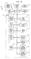
- FIG. 1B shows a combination of steps that illustrate a typical operation of prior art system 20 in generating color control signals for monitor 24 and output device (printer) 26.
- printer 26 is calibrated and spectral absorption table 39 is produced through execution of step 52.
- the imaging process begins, via step 40, by scanning a desired object with image input device 22 to acquire a series of tristimulus values in conventional form, e.g. R,G,B samples of the original. Thereafter, through steps 41 and 42, tristimulus values R,G,B are then converted into CIE standard X,Y,Z tristimulus values and stored in memory 25 as image data 30. Next, through steps 42 and 43, the operator inputs nominal and actual print illuminants 31 and 32, respectively, to generate, via steps 44 and 45, reverse and forward printer model LUTs 33 and 34. Thereafter, through step 46, LUTs 33 and 34 are combined to generate forward-reverse printer model LUTs 35. Once this occurs, steps 48 and 49 are performed to effectively load the process for CRT LUT 36 and non-image "application" software 37, respectively.
- steps 41 and 42 tristimulus values R,G,B are then converted into CIE standard X,Y,Z tristimulus values and stored in memory 25 as image data
- printer control signals 60 e.g., the standard C,M,Y,K printer control signals.
- step 50 computer 21 conventionally transforms tristimulus values X,Y,Z (image data 30) using forward-reverse printer model LUTs 35 to produce transformed tristimulus values X',Y',Z'.
- computer 21 transforms the tristimulus values X',Y',Z' using the process for CRT LUT 36 to generate image control signals I(R,G,B) for color monitor 24.
- a set of control signals NI(R,G,B) for the non-image areas of the CRT are applied to monitor 24 via the non-image "application" software loaded in step 49.
- the image and non-image signals are combined, through step 61, to constitute composite control signals C(R,G,B) for CRT monitor 24.
- color monitor 24 permits the operator to preview images of the original object before printing the image on output device 26.
- System 20 permits the operator to view a CRT image of the object, originally scanned in the illumination of one environment, as it would appear if illuminated by nominal illuminants 31. Additionally, system 20 will display the image on CRT monitor 24 as if it were illuminated by any one of actual illuminants 32. However, it is again noted that the non-image areas of the CRT are generated by NI(R,G,B) control signals that are formed independently of any of the illumination information.
- the operator first generates a first set of six CRT images using one of three nominal print illuminants 31, e.g. the first nominal illuminant, and five actual print illuminants 32 via LUTs 33-36 and steps 42-46, 50, 51 and 61 -- all as shown in FIG. 1B.
- the operator will then view and evaluate this set of six CRT images.
- This process is then repeated for the second and third nominal print illuminants 31, thereby respectively generating second and third sets of six CRT images.
- the operator after viewing the three sets of CRT images, will then decide which sets have a "good" color match and, therefore, which of the three nominal illuminants 31 can be expected to produce the most suitable print when viewed under the specified illuminants 31 and 32. If, for example, the operator feels that second nominal print illuminant 31 produced the only suitable set of CRT images, then the operator may direct the computer 21 to use the spectral data associated with second nominal print illuminant 31 to drive printer (output device) 26 via steps 42, 44, 47 and 60. The print produced by system 20, using the second nominal print illuminant 31, will be expected to have an acceptable overall color match when viewed under specified illuminants 31 and 32.
- five actual print illuminants 32 of the instant example, specified in step 43 will usually include the three nominal print illuminants 31, specified in step 42.
- the CRT images will include images of prints produced by each nominal print illuminant 31 as they will appear when illuminated by the other nominal print illuminants 31.
- Electronic imaging system 120 of the present invention includes prior art image input device 22, computer 21 with memory 25, output device 26, color monitor 24 and operator input device 23. Additionally, system 120 also includes ambient illumination sensor 27 connected as an input to computer 21. Sensor 27 is capable of measuring the spectral content of the ambient light and provides digital spectral data concerning the ambient illumination. Ambient illumination sensor 27 may not be necessary if the spectral data of the ambient illuminants can be supplied by the operator via operator input device 23.
- system 120 may be designed to be a dedicated system that will be permanently installed in an environment having a stable and well-defined ambient illumination; in which case, the spectral data of the ambient illumination may be permanently loaded in computer 21 at installation.
- the ambient illumination is a mixture of sunlight and conventional room lighting that can change appreciably in relatively short time periods.
- Ambient illumination sensor 27 may measure the spectral content directly or indirectly.
- a practical implementation for sensor 27 for directly measuring the spectral content of the illuminant may have between two and thirty-one channels, depending on the accuracy required by the application.
- solid-state sensors, with a glass filter for each desired band of the spectrum are commercially available. Sensors having as many as seventeen overlapping bands may be readily constructed at low cost.
- sensor 27 could function as an illumination discriminator and include a single-channel sensor that can discern a 120-Hertz harmonic modulation characteristic of fluorescent or incandescent lighting, or the lack thereof as in the case of sunlight.
- the spectral information of such standard illumination sources previously stored in a LUT within memory 25, could be accessed via the modulation characteristics detected by sensor 27.
- Suitable illumination discriminators are described in United States patents 4,827,119 (issued to M. J. Gaboury on May 2, 1989) and 4,220,412 (issued to R. A. Shroyer et al on September 2, 1980), both of which are also assigned to the present assignee.
- nominal CRT illuminants 91 are also used. These latter illuminants can have any spectral content that is visually equivalent to the whitepoint of the CRT. For example, one may use the spectrum of a white color typically produced by existing operating system and non-imaging or application software.
- the system and method of the present invention endeavors to achieve a "good" colorimetric match between the image areas on the CRT screen of monitor 24 and the print produced by output device 26.
- Many of the steps for achieving such a colorimetric match are conventional.
- the transformations from standardized colorspaces to and from device-specific control values can be implemented as conventional-type multidimensional look-up tables (LUTs).
- ambient and actual print illuminants 32' are stored, via step 43', in memory 25.
- the ambient illuminant which may change significantly over relatively short time periods, is updated and stored with the actual print illuminants as indicated by numeral 32'.
- the current ambient illuminant data is available in memory 25 to be used by the operator to display an image of a potential print as it would appear in the ambient lighting.
- the actual print illuminants may include all or some of nominal print illuminants 31.
- the ambient illuminant may or may not be included in the set of nominal print illuminants 31 and/or the set of actual print illuminants.
- the ambient illuminant data may be supplied, through step 43', by the operator via input device 23 or by ambient illumination sensor 27.
- System 120 as with prior art system 20, first scans the object, through step 40, to obtain colorimetric samples of the scanned object.
- any acceptable set of colorimetric values may be employed, including the R,G,B tristimulus values referred to above.
- the R,G,B values are then converted by computer 21 into standard tristimulus values, e.g., X,Y,Z, and stored, through step 41, in memory 25 as image data 30.
- system 120 produces reverse printer model LUTs 33 via step 44.
- computer 21 conventionally transforms, through step 47, the X,Y,Z values into printer control signals C,M,Y,K -- the latter shown in step 60.
- step 45 forward printer model LUTs 34'.
- step 46' forward-reverse printer model LUTs 35' are generated by combining LUTs 33 and 34'.
- step 50 computer 21 transforms the X,Y,Z values into X',Y',Z' value, using forward-reverse printer model LUTs 35' and image data 30.
- step 51' computer 21 transforms the X',Y',Z' values into image CRT control signals I(R,G,B)' which are then used to display the image on monitor 24 as that image would appear when illuminated by chosen ambient or actual illuminant 32'.
- computer 21 will also render the remaining portion of the CRT display (background, window borders, icons, and the like) in a manner that is influenced by ambient or actual illumination, in much the same way that colorimetric values of ordinary objects are influenced by such illumination.
- non-image application software 37 is processed by a color translation "shell" 70 to translate the conventional non-image CRT control signals NI(R,G,B) into translated non-image CRT control signals TNI(R,G,B).
- the TNI(R,G,B) signals will display the non-image areas on monitor 24 with colors that would be seen if the operator were to view a print of these non-image areas under the particular actual or ambient illuminant 32' being considered.
- both the image and non-image areas of the display on monitor 24 will have a common whitepoint that will match that of a print being viewed in illuminant 32' being considered.
- the viewer When viewing the image as if illuminated by the ambient light, the viewer will see both the image and the non-image areas on monitor 24 with a whitepoint that matches that of the environment, i.e. the illumination under which the operator will be viewing the print.
- FIG. 3 illustrates the general translation procedure for translating the non-image signals NI(R,G,B) into the translated non-image CRT control signals TNI(R,G,B).
- a typical general-purpose computer which may be executing non-imaging software, will normally use a standard set of output routines 75 that is provided by the operating system for any display output such as drawing characters or graphics. It is noted that the terms "non-imaging software” and “application software” are defined to also include parts of the operating system which perform, for example, window management, cursor movement and error and dialog messages.
- Non-imaging application software 37 will specify in step 37 the desired color of an object to be drawn on monitor 24 in the non-image areas.
- Software 37 will specify this in an illumination-independent colorspace, typically the non-image values NI(R,G,B) used by the monitor.
- "Shell" 70 is built around all relevant operating-system routines, in effect inserting a thin layer of software between application software 37 and the operating system routines. Shell 70 translates the non-image values NI(R,G,B), which are illumination-independent, into translated non-image values TNI(R,G,B), which are illumination-dependent. The TNI(R,G,B) values are then passed on to operating-system routines 75.
- non-color data is sent directly, by step 76, to standard output routines 75.
- the color data is separated, via steps 76 and 77, from the color parameters to leave the NI(R,G,B) signals.
- the NI(R,G,B) values are transformed into translated CRT control signals TNI(R,G,B).
- FIG. 4 illustrates in greater detail the steps involved in translating the non-image (illumination-independent) CRT control signals NI(R,G,B) into the translated (illumination-dependent) CRT control signals TNI(R,G,B).
- Step 80 represents logic routines that isolate the NI(R,G,B) data from the other non-image data as was indicated by steps 76 and 77 shown in FIG. 3.
- conventional forward CRT model LUT 38 transforms the NI(R,G,B) values into the standard tristimulus values X,Y,Z.
- reverse printer model LUT 28 for an imaginary printer transforms the X,Y,Z values into printer signals C,M,Y,K for the imaginary printer using nominal CRT illuminant 91.
- the imaginary printer may or may not represent a real printer and is chosen for convenience only.
- the C,M,Y,K values are then changed, through step 83, into the transformed tristimulus values X',Y',Z' using forward printer model LUT 29 for the imaginary printer and actual or ambient illuminant 32'.
- Transformed tristimulus values X',Y',Z' are now illumination dependent, having first been transformed into printer signals (C,M,Y,K) using nominal CRT illuminant 91 and then transformed, using the appropriate actual or ambient illuminant 32', into values X',Y',Z'.
- the transformed tristimulus values X',Y',Z' are now routinely transformed, through step 51'', with the process for CRT LUT 36 into illumination-dependent CRT control signals, designated here as translated non-image CRT control signals TNI(R,G,B).
- the TNI(R,G,B) control signals are combined, through step 84, with appropriate non-color and other non-image application software signals.
- CRT and printer models including forward CRT model LUT 38, reverse imaginary printer model LUT 28 and forward imaginary printer model LUT 29.
- the color transformation applied to CRT monitor 24 is similar to that used to predict printer output colors.
- the color specifications supplied by the application software are translated, via steps 81 and 82, into printer control values C,M,Y,K as if on a print, and then the appearance of this print is calculated, through step 83, based on the actual or ambient illuminants 32'.
- the first portion of this process i.e. steps 81 and 82, is analogous to generating an imaginary print from data in the R,G,B colorspace of the monitor.
- the illumination-independent R,G,B value is first converted to X,Y,Z values according to the calibration of monitor 24 which produces forward CRT model LUT 38.
- the control values C,M,Y,K for the imaginary printer are then computed, based on reverse imaginary print model LUT 28, as if the print were intended to be illuminated at the whitepoint of the CRT display of monitor 24.
- negative C,M,Y,K dye concentrations may be allowed since, after all, the printer is imaginary and system 120 will not actually be printing based on these values.
- the negative values may be thought of as amplifying the respective region of the spectrum, rather than attenuating it.
- a C, M, Y printer may alternatively be used.
- Forward imaginary printer model LUT 29 determines the apparent color, given the control signals C,M,Y,K and the spectral distribution of the actual or ambient illuminant, and maps this into X',Y',Z' values. Then, using the monitor calibration, the X',Y',Z' values are converted into the illumination-dependent TNI(R,G,B) values as given to operating system routines 75. It is noted that forward imaginary printer model LUT 29 depends on the actual or ambient illuminants 32', specifically on which illuminant is being previewed. In the case of the ambient illuminant, forward imaginary printer model LUT 29 must be recalculated each time that the ambient illuminant changes.
- printer model used for color translation of non-image areas need not be the same as the printer model used for the image; for example, any "reasonable" arbitrary dye absorption spectra may be used to model the printer for color translation.
- FIGs. 5-7 Specific examples of the computer transformations involved in steps 81, 82 and 51'' are illustrated in FIGs. 5-7.
- FIG. 5 illustrates the calculations performed by forward CRT model LUT 38 in step 81.
- the NI(R,G,B) values which represent typical CRT control signals for the non-image areas, are transformed into radiance values by three one-dimensional (1-D) LUTs; namely, RED 1-D LUT 101, GREEN 1-D LUT 102, and BLUE 1-D LUT 103.
- the radiance values are multiplied, in step 104, by a (3X3) matrix M T E to produce the X,Y,Z tristimulus values, where M T is a conventional (3X31) CIE color matching function matrix and E is a conventional (31X3) phosphor emission spectra matrix, as measured.
- the matrix dimension "31" is used as a typical example and assumes that the spectrum is sampled in 10nm increments, from 400nm to 700nm. Of course, finer sampling and/or a larger range of the spectrum may be used if desired.
- Equation (1) may be solved (as occurs in FIG. 6) by using a well-known Newton-Raphson search to find its inverse, i.e. c as a function of x .
- the matrix variable H is defined as follows: where: f1, f2, f3 are the three component functions of F( c ).
- Equation (2) Equation (2) will then yield:
- the Newton-Raphson search begins, through step 110, with the initialization of the c vector.
- the c vector having components C,M,Y c , may be set equal to (0,0,0) as a reasonable initial value.
- the c vector is then used in step 112 to calculate H by a numerical calculation of the partial derivatives.
- Matrix H is then inverted, via step 113, to obtain H ⁇ 1.
- step 115 the difference between c: and c is determined.
- step 115 the difference calculated in step 115 is sufficiently small.
- FIG. 7 shows typical computer calculations that may be carried out in step 51'' to convert the X',Y',Z' values to the translated non-image CRT control signal TNI(R,G,B).
- the X',Y',Z' values are multiplied, in step 119, by the inverse of the (3X3) matrix M T E used in step 81 (see FIG. 5).
- the multiplication resulting from step 119 shown in FIG. 7 will produce R,G,B radiance values that are transformed into the TNI(R,G,B) values via the RED, GREEN and BLUE one-dimensional LUTs in steps 120, 121 and 122, which are the inverse of the transfer functions of each of the CRT channels, as measured, i.e. control signal as a function of radiance.
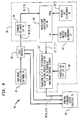
- FIG. 8 illustrates an alternative color translation system 90' for use in translating color in accordance with step 78 of FIG. 3.
- System 90' is similar to system 90 shown in FIG. 4 with the only difference therebetween being the elimination of forward and reverse imaginary printer model LUTs 28 and 29, and the substitution of whitepoint adaptation step 89 therefor.
- the mapping of the X,Y,Z values into the X',Y',Z' values is the reverse of the adaptation method disclosed in co-pending United States Patent Application "Method for the Reproduction of Color Images Based on Viewer Adaptation" (serial number 07/678,485; filed April 1, 1991 by inventor D. Statt -- the "Statt application", and also assigned to the present assignee) which is incorporated by reference herein.
- the present invention is useful in electronic imaging systems and particularly for implementing an accurate print preview function in such systems.
- a highly acceptable color match can be obtained, even under a variety of different illuminants, between a color image as previewed on a CRT monitor and that which will appear on a color print generated by such a system.
- the invention will permit a user of an electronic imaging system to generate more accurate color prints than has heretofore occurred through use of electronic imaging systems known in the art.
Landscapes
- Engineering & Computer Science (AREA)
- Multimedia (AREA)
- Signal Processing (AREA)
- Controls And Circuits For Display Device (AREA)
- Facsimile Image Signal Circuits (AREA)
- Dot-Matrix Printers And Others (AREA)
- Color Image Communication Systems (AREA)
Abstract
A technique, applicable for use in implementing a print preview function in a color electronic imaging system, that, under a variety of different ambient lighting conditions, will yield a highly acceptable color match between a color image appearing on a CRT monitor and that which will be produced by the system as a printed version of the same image. Specifically, a computer system (120) is employed to scan an image and, through an ambient illumination sensor (27), senses the spectral content of the ambient illumination. The computer displays the scanned image along with various non-image information which can be used to adjust the color of the image. The computer transforms the color of the scanned image and the non-image information such that a resultant display of the image and the non-image information on a color monitor (24) will show the appearance of a print when the print is viewed under the ambient illumination. The transformation of the non-image information includes transforming non-image monitor control signals into a first set of tristimulus values which are, in turn, transformed into printer control signals for an imaginary printer. These printer control signals are then transformed into tristimulus values using the sensed spectral content of the illuminant. This latter set of values are used to produce monitor control signals that are applied to the monitor.
Description
- This invention relates to the reproduction of color images and, more particularly, to a technique suitable for use in implementing, for example, a print preview function in a color electronic imaging system that, under a variety of different ambient lighting conditions, will yield a highly acceptable color match between a color image appearing on a CRT display and that which will be produced by the system as a printed version of the same image.
- One of the goals of color electronic imaging systems, used extensively in the field of desktop publishing, is to obtain a highly acceptable ("good") color match between a "soft" display (e.g. a cathode ray tube --CRT display) and a printed output of a reproduction system. A system that has a highly acceptable color match provides a user with an accurate prediction of a final printed output as it would appear when viewed under different illuminants. The current state of the art in obtaining a "good" color match in color electronic imaging systems is to first optimize the color match between a scanned original and the printed output under a "nominal" illuminant (i.e., the illuminant under which the print is intended to be viewed), and then model the appearance of the print under various "actual" illuminants (i.e. the variety of other illuminants under which the print could reasonably be expected to be viewed). In such systems, each colorimetric value that would appear on the print is duplicated on the CRT display (monitor) for viewing by the user.
- Although such prior art systems have served the purpose, for primarily two reasons they have not proved entirely satisfactory in producing a "good" color match between the CRT display and the resulting print. First, human observers viewing an image on a CRT display will tend to adapt to a whitepoint of this display. This adaptation is based on all illuminated areas on the CRT display, including non-image areas, such as illustratively window borders and/or a so-called "desktop" background. As a result, colors that appear on the CRT display which are, in fact, an exact match with those in the print will instead appear to an observer as being mismatched.
- Second, the selection of actual illuminants which can be modelled by the system is usually somewhat limited. In fact, the illumination of the print under ambient light may differ from all of the modelled illuminants. Consequently, the appearance of the print in the working environment, i.e., under ambient light, will not exactly match the image as shown on the CRT display. As such, the user will be viewing an apparent mismatch.
- To obtain a color match sufficient for user viewing in the working environment, several well known visualization effects must be taken into account. One such effect is metamerism. Generally speaking, metamerism is the ability of two different objects, having differing spectral reflectance characteristics, to appear to an observer (whether a human or an instrument), under one illuminant, as having the same color. However, under another illuminant, the objects will appear different from each other. Such objects are commonly referred to as metameric objects. The color of any object is determined by both its spectral reflectivity or transmissivity and the spectral content of its illuminant. Metamerism occurs because many different spectral reflectance characteristics can all exhibit the same set of color coordinate values. However, metameric objects will exhibit different, i.e mismatched, colors if the observers have different spectral responses or if illuminants with differing spectral content are used to view both objects at once. See, e.g., pages 21-23 of F. W. Billmeyer et al, Principles of Color Technology, 2nd Edition (©1981: John Wiley & Sons, Inc., New York) for a discussion of metamerism.
- Now, it is well known that the spectral content of an illuminant modifies the color of an image of an object being captured through a conventional photographic or electronic process and also modifies the color of an image on a photographic or electronic print that is being viewed or scanned. Different types of light sources will have differing spectral contents. Some of these light sources, while being spectrally different, may also have the same or different colorimetric whitepoints. In either case, the color of illuminated objects will differ in response to the different light sources. Though humans will adapt to various whitepoints, metamerism, as described above, may cause the perceived color of objects, including those appearing on a CRT display, to change in a manner different from that which would be expected solely from the adaptation.
- Metamerism has the following two effects on an electronic imaging system. First, as expected, when an original is scanned by a sensor, resulting image data is influenced by both the spectral content of the illumination source along with the spectral response of the sensor. If a three-channel sensor is used to scan an original, as is typically the case, it will be nearly impossible to subsequently determine exactly what the color of the original would have been had a different illuminant been used to illuminate the original during scanning. At the present time, it is simply not economically feasible to record enough channels of data to represent the appearance of the original under each one of a number of differing lighting conditions, i.e. under each of a variety of different illuminants. As such, this restricts a user's ability to undertake accurate side-by-side color matching of the print with the original in the working environment. Hence, for side-by-side color matching of such prints, the user must rely on using illumination that is spectrally equivalent to that used in the scanning process, else color mismatches will likely be produced.
- Second, when a print is produced, its image data must generally be processed in a manner that is specific to a nominal illuminant, e.g. the illuminant under which the print is expected to be viewed. However, it is simply impractical to require a user to view a print under only one specific light source. Therefore, it is necessary to determine that the print will appear satisfactory under a variety of different light sources. In that regard, one can now model how a given print will appear under any light source including an ambient light source.
- People judge color relative to their environment. People use familiar objects of known colors as reference points and often discount the color of the ambient light source. For example, if a person is placed in a room with yellow illumination, handed a white piece of paper, and asked what color the paper was, the response would generally be "white," even though the light reflected from the paper was yellow. This response occurs because the viewer has innately and subconsciously compensated for the fact that all objects in the room appear yellowish.
- In recent experiments conducted by Roy Berns at the Rochester Institute of Technology in Rochester, New York (the "Berns experiments"), it was shown that people generally adapt to an image on a CRT display independently of the color of the ambient light. In the Berns experiments, human subjects were asked to match colors painted on a CRT display with the same colors that appeared on a printed chart. When the whitepoint of the background of the image appearing on the CRT display differed from that of the ambient light, these subjects made errors in matching the colors. These errors arose because the subjects judged the colors on the CRT display relative to that of the background of the displayed image. In this instance, the subjects used the non-image areas displayed on the CRT (e.g. window borders and "desktop" background) as reference points independent of the ambient light. The subjects responded in this fashion evidently because they realized that the CRT display generates its own light source. As such, these experiments indicate that the "environment" for color reference points of a CRT image is generally limited to whatever is shown on the screen of the CRT, especially in the non-image, e.g. background, areas.
- These visualization effects complicate attempts to provide an acceptable color match between an image displayed on a CRT display and a print of that image. If an electronic imaging system attempts to present a colorimetrically matched image on a CRT display, a user will have adapted to the whitepoint of the CRT display and hence will perceive that the image is displayed with incorrect color when, in fact, it is not.
- One traditional approach to dealing with these complications is to show the image in the CRT display with all non-image areas "blanked out." Unfortunately, this approach disadvantageously eliminates any information previously contained in areas that have been "blanked out". More important, the "blanked-out" areas which, for example, may be solid blue or yellow or white, will still have a whitepoint that normally will adversely affect a viewer's perception of the colors of the image displayed on the CRT. For example, if the "blanked-out" area is black, the viewer will perceive the CRT image as it would appear with a black border which is not the environment in which the print will be actually viewed.
- Another such approach involves "adapting" the image appearing on a CRT display to the whitepoint of the display in order to compensate for how a user will adapt to the whitepoint of the display. See, specifically, co-pending United States Patent Application "Method for the Reproduction of Color Images Based on Viewer Adaptation" (serial number 07/678,485; filed April 1, 1991 by inventor D. Statt and assigned to the present assignee) which addresses this approach. Although this approach can provide adequate results, it does not insure that the user's adaptation to the CRT display will be exactly the same as that to the environment in which the print will be actually viewed.
- Consequently, a need still exists in the art in connection with the on-going development of color electronic imaging systems for a technique, particularly for use in implementing a print preview function, that, under a variety of different ambient lighting conditions, will effectively yield a highly acceptable color match between a color image appearing on a CRT display and that which will be produced by such a system as a printed version of the same image. Such a technique must also be substantially unaffected by viewer adaptation to the whitepoint of the CRT display as well as any associated observer metamerism.
- Accordingly, an object of the present invention is to provide a print preview function in a color electronic imaging system that will provide a highly acceptable color match between a color image appearing on a CRT monitor, under a variety of different ambient lighting conditions, and that which will be produced as a print by such a system.
- To attain this and other objects, the present invention is a color electronic imaging system that has a color input means for providing color input data of an object, an illumination input means for providing illumination data on selective illuminants, and a color display monitor for displaying the object and non-image information. "Non-image" is defined to be anything, such as illustratively window borders, menus and icons, that is displayed but is not, from an application standpoint, the image that a user is manipulating. The system also includes a computer which is connected to the color input means, the illumination input means, and the color display monitor. The computer generates non-image color control signals for displaying the non-image information on the monitor and selectively transforms both the color input data and the non-image color control signals, using the spectral content of a selected illuminant, into a composite color control signal for the monitor in order to display a color image of the object and the non-image information as they would appear on a print when the print is viewed under the selected illuminant, such as the ambient illuminant.
- The system also includes an illuminant sensor for obtaining spectral information of the ambient light source. This information is then used to adjust the image colors that are to appear on the CRT display.
- Broadly speaking, my invention provides an electronic imaging system with a print preview function through which the spectral content of the ambient illumination is used to change the colors of the entire display, not just the image areas, in the exact same manner that the colors that would appear in a print of the image as produced by the system would be affected by the spectral content of its ambient illumination. Consequently, the system will cause all image and non-image areas of the display to behave as if they are illuminated by the same ambient light source that would be illuminating the print. As a result, a user's color "frame of reference" on the display will match that of the working environment. By preventing separate adaptation between the display and the environment, users will be better able to match colors on the display with colors on the print and thereby generate more accurate color prints than has been heretofore possible with electronic imaging systems known in the art. Furthermore, since the colors that a user will perceive from the CRT display are substantially the same colors that will be seen in the actual print that will be produced by the system, a user will gain increased and more effective control over a color printing process through an electronic imaging system that utilizes my inventive technique than through such a system that does not.
- Of course, owing to the effects of metamerism and gamut limitations inherent in a typical color printing process, it is quite likely that some residual color mismatches will result from use of my inventive technique between the colors in a print and those in a corresponding original. Clearly then, my invention matches the colors, both colorimetrically and as perceived by a viewer, that appear in the CRT display to those that will appear on the print, but not the colors in the print to those in the original. Nevertheless, due to the accurate ability of my inventive technique to predict resulting colors of the print, use of my invention will allow a user to interactively adjust the colors of the print to be closer to those of the original than would likely result if my inventive technique were not to be used.
- The teachings of the present invention may be readily understood by considering the following detailed description in conjunction with the accompanying drawings, in which:
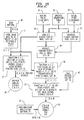
- FIG. 1A is a block diagram of a prior art color electronic imaging system;
- FIG. 1B is a functional block diagram illustrating the method of operation of
prior art system 20 shown in FIG. 1A; - FIG. 2A is a block diagram of a preferred embodiment of my present invention;
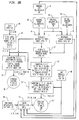
- FIG. 2B is functional block diagram illustrating the method of operation of the embodiment shown in FIG. 2A;
- FIG. 3 is a functional block diagram illustrating the operation of the color translation shell (step 70) shown in FIG. 2B;
- FIG. 4 is a functional block diagram illustrating in detail
Translate Color Step 78 shown in FIG. 3; - FIG. 5 is a functional block diagram illustrating the transformation for the Forward CRT Model Look Up Table (LUT) (step 81) shown in FIG. 4;
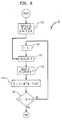
- FIG. 6 is a functional block diagram illustrating the transformation for the Reverse Imaginary Printer Model LUT (step 82) shown in FIG. 4;
- FIG. 7 is a functional block diagram illustrating Tristimulus
Value Transforming Step 51'' shown in FIG. 4; and - FIG. 8 is a functional block diagram, similar to FIG. 4, illustrating a modification to my preferred embodiment.
- To facilitate understanding, identical reference numerals have been used, where possible, to denote identical elements that are common to various figures.
- Referring to the drawings, FIG. 1A shows prior art color
electronic imaging system 20 havingcomputer 21 connected to imageinput device 22,operator input device 23, color monitor (CRT display) 24,output device 26, andmemory 25.Image input device 22 may be a conventional digital device, such as illustratively a color film scanner or electronic color camera, that samples the radiant flux of an object and generates digital color information signals, such as for standard primary colors red, green, blue (R,G,B). Alternatively,input device 22 may be a computer color graphics generator having an instrument, such as a keyboard, mouse or pen, that permits an operator to electronically draw or trace and paint an object. In any case,computer 21 typically receives tristimulus values as, for example, R,G,B samples or equivalent signals. The R,G,B samples are typically converted to the CIE (Commission Internationale de l'Eclairage) standard X,Y,Z tristimulus values and then stored asimage data 30 inmemory 25. Blocks 30-39 specify particular items that are stored within this memory. -
Computer 21 performs selected operations onimage data 30 under the control of an operator, viaoperator input device 23, e.g. a keyboard or a mouse, as the operator previews an image of the object on the screen ofcolor monitor 24. The computer can be implemented using either a general-purpose computer or a special-purpose computer designed for image and/or graphics processing and color graphics printing viaoutput device 26.Output device 26 may be a color printer, a color plotter, or any other suitable device for transferring a color image onto an output medium, such as paper or any other suitable "hard-copy" print surface. - In preparation for viewing the color image of an original, the operator typically specifies, via
input device 23, a set ofactual print illuminants 32 and one or morenominal print illuminants 31. The spectral content of theseilluminants memory 25. This may be accomplished either by simply selecting among standard commercial illuminants that have had their spectral contents previously stored incomputer 21, or by measuring the spectra associated with each one of various different illuminants and then selecting one of measured spectrums. - Look-up tables (LUTs) 33 and 34, produced by
computer 21 during printer calibration, are also stored inmemory 25. When output device (printer) 26 is calibrated in a conventional manner, a set of printed test patches is measured. The spectral absorption of each patch is either measured, or calculated based on measured tristimulus values, or other colorimetrically defined units, and prior knowledge of the spectral absorption of each printing dye. A three- or four-dimensional spectral absorption table 39 is then constructed and stored inmemory 25. Each axis of the table 39 is indexed by printer control signals; the number of axes depends on the number of printer channels (e.g. C,M,Y or C,M,Y,K). Each entry in table 39 contains spectral absorption data, i.e. each entry contains a vector of absorption values sampled periodically through the spectrum. This absorption data is the combined absorption of all of the dye layers, as printed and measured. Table 39 remains constant until the next time the printer is calibrated; it does not depend on ambient lighting. - Using spectral absorption table 39, each
nominal print illuminant 31 is used to generate well-known reverseprinter model LUT 33. Also, using table 39 andactual print illuminants 32,computer 21 generates a set of well-known forwardprinter model LUTs 34 that, in turn, is combined with reverseprinter model LUTs 33 to produce a set of forward-reverseprinter model LUTs 35. - Also residing in
memory 25 is a process forCRT LUT 36 and non-image "application software" 37. In this context and broadly speaking, the term "application software" is defined as including all software that would generate CRT data, such as graphics, text, icons, windows, and the like, whether generated by an operating system, a shell, a user-generated program, or other program. In addition, the term "non-image" is defined to be anything, such as illustratively window borders, menus and icons, that is displayed but is not, from an application standpoint, the image that a user is manipulating. - FIG. 1B shows a combination of steps that illustrate a typical operation of
prior art system 20 in generating color control signals formonitor 24 and output device (printer) 26. During initial set up,printer 26 is calibrated and spectral absorption table 39 is produced through execution ofstep 52. - The imaging process begins, via
step 40, by scanning a desired object withimage input device 22 to acquire a series of tristimulus values in conventional form, e.g. R,G,B samples of the original. Thereafter, throughsteps memory 25 asimage data 30. Next, throughsteps actual print illuminants steps printer model LUTs step 46,LUTs printer model LUTs 35. Once this occurs, steps 48 and 49 are performed to effectively load the process forCRT LUT 36 and non-image "application"software 37, respectively. - Then, using reverse
printer model LUTs 33,computer 21 conventionally transforms, throughstep 47, X,Y,Z image data 30. The transformation produces conventional printer control signals 60, e.g., the standard C,M,Y,K printer control signals. - Thereafter, through
step 50,computer 21 conventionally transforms tristimulus values X,Y,Z (image data 30) using forward-reverseprinter model LUTs 35 to produce transformed tristimulus values X',Y',Z'. Throughstep 51,computer 21 transforms the tristimulus values X',Y',Z' using the process forCRT LUT 36 to generate image control signals I(R,G,B) forcolor monitor 24. Additionally, a set of control signals NI(R,G,B) for the non-image areas of the CRT are applied to monitor 24 via the non-image "application" software loaded instep 49. The image and non-image signals are combined, throughstep 61, to constitute composite control signals C(R,G,B) for CRT monitor 24. - As indicated above, color monitor 24 permits the operator to preview images of the original object before printing the image on
output device 26.System 20 permits the operator to view a CRT image of the object, originally scanned in the illumination of one environment, as it would appear if illuminated bynominal illuminants 31. Additionally,system 20 will display the image on CRT monitor 24 as if it were illuminated by any one ofactual illuminants 32. However, it is again noted that the non-image areas of the CRT are generated by NI(R,G,B) control signals that are formed independently of any of the illumination information. - To illustrate a typical operation of
prior art system 20 in greater detail, assume that an operator wishes to evaluate the potential appearance of color prints to be produced by output device 26 (see FIG. 1A) from a single set ofimage data 30 to determine which prints will most likely produce a highly acceptable ("good") color match. Assume that the operator has decided to select three differentnominal print illuminants 31 to driveoutput device 26. In effect, the operator will be evaluating which of the three differentnominal print illuminants 31 will produce a print with a "good" color match by viewing CRT images of the potential prints as they will appear when illuminated by each ofilluminants - To do this, the operator first generates a first set of six CRT images using one of three
nominal print illuminants 31, e.g. the first nominal illuminant, and fiveactual print illuminants 32 via LUTs 33-36 and steps 42-46, 50, 51 and 61 -- all as shown in FIG. 1B. The operator will then view and evaluate this set of six CRT images. This process is then repeated for the second and thirdnominal print illuminants 31, thereby respectively generating second and third sets of six CRT images. The operator, after viewing the three sets of CRT images, will then decide which sets have a "good" color match and, therefore, which of the threenominal illuminants 31 can be expected to produce the most suitable print when viewed under the specified illuminants 31 and 32. If, for example, the operator feels that secondnominal print illuminant 31 produced the only suitable set of CRT images, then the operator may direct thecomputer 21 to use the spectral data associated with second nominal print illuminant 31 to drive printer (output device) 26 viasteps system 20, using the secondnominal print illuminant 31, will be expected to have an acceptable overall color match when viewed under specifiedilluminants - It is noted that, in practice, five
actual print illuminants 32 of the instant example, specified instep 43, will usually include the threenominal print illuminants 31, specified instep 42. In this way, the CRT images will include images of prints produced by eachnominal print illuminant 31 as they will appear when illuminated by the othernominal print illuminants 31. -
Electronic imaging system 120 of the present invention, illustrated in FIGs. 2A and 2B, includes prior artimage input device 22,computer 21 withmemory 25,output device 26, color monitor 24 andoperator input device 23. Additionally,system 120 also includesambient illumination sensor 27 connected as an input tocomputer 21.Sensor 27 is capable of measuring the spectral content of the ambient light and provides digital spectral data concerning the ambient illumination.Ambient illumination sensor 27 may not be necessary if the spectral data of the ambient illuminants can be supplied by the operator viaoperator input device 23. For example,system 120 may be designed to be a dedicated system that will be permanently installed in an environment having a stable and well-defined ambient illumination; in which case, the spectral data of the ambient illumination may be permanently loaded incomputer 21 at installation. However, in many cases, the ambient illumination is a mixture of sunlight and conventional room lighting that can change appreciably in relatively short time periods. -
Ambient illumination sensor 27 may measure the spectral content directly or indirectly. A practical implementation forsensor 27 for directly measuring the spectral content of the illuminant may have between two and thirty-one channels, depending on the accuracy required by the application. In this regard, solid-state sensors, with a glass filter for each desired band of the spectrum, are commercially available. Sensors having as many as seventeen overlapping bands may be readily constructed at low cost. - In some environments, an indirect measurement of ambient lighting is sufficient. To indirectly determine the spectrum of the ambient illumination,
sensor 27 could function as an illumination discriminator and include a single-channel sensor that can discern a 120-Hertz harmonic modulation characteristic of fluorescent or incandescent lighting, or the lack thereof as in the case of sunlight. The spectral information of such standard illumination sources, previously stored in a LUT withinmemory 25, could be accessed via the modulation characteristics detected bysensor 27. Suitable illumination discriminators are described in United States patents 4,827,119 (issued to M. J. Gaboury on May 2, 1989) and 4,220,412 (issued to R. A. Shroyer et al on September 2, 1980), both of which are also assigned to the present assignee. - In addition to
nominal print illuminants 31, as shown in FIG. 2B,nominal CRT illuminants 91 are also used. These latter illuminants can have any spectral content that is visually equivalent to the whitepoint of the CRT. For example, one may use the spectrum of a white color typically produced by existing operating system and non-imaging or application software. - As indicated above, the system and method of the present invention endeavors to achieve a "good" colorimetric match between the image areas on the CRT screen of
monitor 24 and the print produced byoutput device 26. Many of the steps for achieving such a colorimetric match are conventional. The transformations from standardized colorspaces to and from device-specific control values can be implemented as conventional-type multidimensional look-up tables (LUTs). - As can be seen from FIGs. 2A and 2B, ambient and actual print illuminants 32' are stored, via step 43', in
memory 25. The ambient illuminant, which may change significantly over relatively short time periods, is updated and stored with the actual print illuminants as indicated by numeral 32'. The current ambient illuminant data is available inmemory 25 to be used by the operator to display an image of a potential print as it would appear in the ambient lighting. As indicated above, the actual print illuminants may include all or some ofnominal print illuminants 31. The ambient illuminant may or may not be included in the set ofnominal print illuminants 31 and/or the set of actual print illuminants. As discussed earlier, the ambient illuminant data may be supplied, through step 43', by the operator viainput device 23 or byambient illumination sensor 27. -
System 120, as withprior art system 20, first scans the object, throughstep 40, to obtain colorimetric samples of the scanned object. Again, any acceptable set of colorimetric values may be employed, including the R,G,B tristimulus values referred to above. Using conventional techniques, the R,G,B values are then converted bycomputer 21 into standard tristimulus values, e.g., X,Y,Z, and stored, throughstep 41, inmemory 25 asimage data 30. - As with
prior art system 20,system 120 produces reverseprinter model LUTs 33 viastep 44. Using reverseprinter model LUTs 33 andimage date 30,computer 21 conventionally transforms, throughstep 47, the X,Y,Z values into printer control signals C,M,Y,K -- the latter shown instep 60. - Using spectral absorption table 39 and actual and ambient print illuminants 32',
computer 21 generates, through step 45', forward printer model LUTs 34'. In step 46', forward-reverse printer model LUTs 35' are generated by combiningLUTs 33 and 34'. Thereafter, through step 50',computer 21 transforms the X,Y,Z values into X',Y',Z' value, using forward-reverse printer model LUTs 35' andimage data 30. Instep 51',computer 21 transforms the X',Y',Z' values into image CRT control signals I(R,G,B)' which are then used to display the image onmonitor 24 as that image would appear when illuminated by chosen ambient or actual illuminant 32'. However, in addition to previewing the print image as it would appear under ambient or actual illumination 32',computer 21 will also render the remaining portion of the CRT display (background, window borders, icons, and the like) in a manner that is influenced by ambient or actual illumination, in much the same way that colorimetric values of ordinary objects are influenced by such illumination. - As illustrated in FIG. 2B,
non-image application software 37 is processed by a color translation "shell" 70 to translate the conventional non-image CRT control signals NI(R,G,B) into translated non-image CRT control signals TNI(R,G,B). The TNI(R,G,B) signals will display the non-image areas onmonitor 24 with colors that would be seen if the operator were to view a print of these non-image areas under the particular actual or ambient illuminant 32' being considered. As such, both the image and non-image areas of the display onmonitor 24 will have a common whitepoint that will match that of a print being viewed in illuminant 32' being considered. When viewing the image as if illuminated by the ambient light, the viewer will see both the image and the non-image areas onmonitor 24 with a whitepoint that matches that of the environment, i.e. the illumination under which the operator will be viewing the print. - FIG. 3 illustrates the general translation procedure for translating the non-image signals NI(R,G,B) into the translated non-image CRT control signals TNI(R,G,B). A typical general-purpose computer, which may be executing non-imaging software, will normally use a standard set of
output routines 75 that is provided by the operating system for any display output such as drawing characters or graphics. It is noted that the terms "non-imaging software" and "application software" are defined to also include parts of the operating system which perform, for example, window management, cursor movement and error and dialog messages. -
Non-imaging application software 37 will specify instep 37 the desired color of an object to be drawn onmonitor 24 in the non-image areas.Software 37 will specify this in an illumination-independent colorspace, typically the non-image values NI(R,G,B) used by the monitor. "Shell" 70 is built around all relevant operating-system routines, in effect inserting a thin layer of software betweenapplication software 37 and the operating system routines.Shell 70 translates the non-image values NI(R,G,B), which are illumination-independent, into translated non-image values TNI(R,G,B), which are illumination-dependent. The TNI(R,G,B) values are then passed on to operating-system routines 75. - Specifically, within
step 70, non-color data is sent directly, bystep 76, tostandard output routines 75. Alternatively, the color data is separated, viasteps step 78, the NI(R,G,B) values are transformed into translated CRT control signals TNI(R,G,B). - FIG. 4 illustrates in greater detail the steps involved in translating the non-image (illumination-independent) CRT control signals NI(R,G,B) into the translated (illumination-dependent) CRT control signals TNI(R,G,B).
Step 80 represents logic routines that isolate the NI(R,G,B) data from the other non-image data as was indicated bysteps step 81 shown in FIG. 4, conventional forwardCRT model LUT 38 transforms the NI(R,G,B) values into the standard tristimulus values X,Y,Z. Next, viastep 82, reverseprinter model LUT 28 for an imaginary printer transforms the X,Y,Z values into printer signals C,M,Y,K for the imaginary printer usingnominal CRT illuminant 91. The imaginary printer may or may not represent a real printer and is chosen for convenience only. The C,M,Y,K values are then changed, throughstep 83, into the transformed tristimulus values X',Y',Z' using forwardprinter model LUT 29 for the imaginary printer and actual or ambient illuminant 32'. Transformed tristimulus values X',Y',Z' are now illumination dependent, having first been transformed into printer signals (C,M,Y,K) usingnominal CRT illuminant 91 and then transformed, using the appropriate actual or ambient illuminant 32', into values X',Y',Z'. The transformed tristimulus values X',Y',Z' are now routinely transformed, throughstep 51'', with the process forCRT LUT 36 into illumination-dependent CRT control signals, designated here as translated non-image CRT control signals TNI(R,G,B). The TNI(R,G,B) control signals are combined, throughstep 84, with appropriate non-color and other non-image application software signals. Oncestep 80 is complete, then, as shown in FIG. 2B, the composite CRT control signals C(R,G,B)' are formed and applied to monitor 24 via step 61'. - It is noted that those skilled in these arts should be readily familiar with the formation of CRT and printer models including forward
CRT model LUT 38, reverse imaginaryprinter model LUT 28 and forward imaginaryprinter model LUT 29. Furthermore, the color transformation applied to CRT monitor 24 is similar to that used to predict printer output colors. The color specifications supplied by the application software are translated, viasteps step 83, based on the actual or ambient illuminants 32'. The first portion of this process, i.e. steps 81 and 82, is analogous to generating an imaginary print from data in the R,G,B colorspace of the monitor. The illumination-independent R,G,B value, as supplied by the application software, is first converted to X,Y,Z values according to the calibration ofmonitor 24 which produces forwardCRT model LUT 38. The control values C,M,Y,K for the imaginary printer are then computed, based on reverse imaginaryprint model LUT 28, as if the print were intended to be illuminated at the whitepoint of the CRT display ofmonitor 24. To preserve the gamut range of the CRT, negative C,M,Y,K dye concentrations may be allowed since, after all, the printer is imaginary andsystem 120 will not actually be printing based on these values. The negative values may be thought of as amplifying the respective region of the spectrum, rather than attenuating it. For simplicity, a C, M, Y printer may alternatively be used. - The latter portion of the process, steps 83 and 51'', function similarly to the print preview processing described earlier. Forward imaginary
printer model LUT 29 determines the apparent color, given the control signals C,M,Y,K and the spectral distribution of the actual or ambient illuminant, and maps this into X',Y',Z' values. Then, using the monitor calibration, the X',Y',Z' values are converted into the illumination-dependent TNI(R,G,B) values as given tooperating system routines 75. It is noted that forward imaginaryprinter model LUT 29 depends on the actual or ambient illuminants 32', specifically on which illuminant is being previewed. In the case of the ambient illuminant, forward imaginaryprinter model LUT 29 must be recalculated each time that the ambient illuminant changes. - The above process steps can be combined into one LUT. Note that the printer model used for color translation of non-image areas need not be the same as the printer model used for the image; for example, any "reasonable" arbitrary dye absorption spectra may be used to model the printer for color translation.
- Specific examples of the computer transformations involved in
steps - As shown, FIG. 5 illustrates the calculations performed by forward
CRT model LUT 38 instep 81. The NI(R,G,B) values, which represent typical CRT control signals for the non-image areas, are transformed into radiance values by three one-dimensional (1-D) LUTs; namely, RED 1-D LUT 101, GREEN 1-D LUT 102, and BLUE 1-D LUT 103. The radiance values are multiplied, instep 104, by a (3X3) matrix M T E to produce the X,Y,Z tristimulus values, where M T is a conventional (3X31) CIE color matching function matrix and E is a conventional (31X3) phosphor emission spectra matrix, as measured. The matrix dimension "31" is used as a typical example and assumes that the spectrum is sampled in 10nm increments, from 400nm to 700nm. Of course, finer sampling and/or a larger range of the spectrum may be used if desired. - The computer transformation performed in
step 82 by the reverse imaginaryprinter model LUT 28 may be performed using the following equation:

where: - c
- represents the C,M,Yc values of a dye concentration vector (only three values are used instead of the four, C,M,Y,K, for simplification. Since the "Y" in the X,Y,Z and C,M,Y values are not the same, they will be designated here as Yx and Yc, respectively, to avoid confusion);
- D
- is a (31X3) dye spectral density matrix;
- Iv1
- is a (31X31) diagonal illumination matrix for nominal CRT illuminant 91 (spectral illumination values situated on the diagonal of the matrix and zeros elsewhere);
- MT
- is a (3X31) CIE color matching function matrix; and
- x
- represents the X,Yx,Z values.
- Equation (1) may be solved (as occurs in FIG. 6) by using a well-known Newton-Raphson search to find its inverse, i.e. c as a function of x. In performing the Newton-Raphson search, the matrix variable H is defined as follows:

where:
f₁, f₂, f₃ are the three component functions of F(c). -

- The Newton-Raphson search (used in the implementation of
step 82 shown in FIG. 6) begins, throughstep 110, with the initialization of the c vector. For example, the c vector, having components C,M,Yc, may be set equal to (0,0,0) as a reasonable initial value. The c vector is then used instep 112 to calculate H by a numerical calculation of the partial derivatives. Matrix H is then inverted, viastep 113, to obtain H⁻¹. The value c: is calculated, throughstep 114, using the following equation:

Instep 115, the difference between c: and c is determined. If the difference is small, then the process is ended and the C,M,Yc values for the latest c: are supplied as output values. If, however, the difference is large, then c is assigned the value of c: instep 111. The process is then repeated until the difference calculated instep 115 is sufficiently small. - To convert from the C,M,Y (or C,M,Y,K) values to the X',Y',Z' values in step 83 (see FIG. 4) the following calculation may be carried out:

where: - x'
- represents the output values X',Y',Z';
- c
- represents the input values C,M,Y (or C,M,Y,K);
- D
- is a (31X3) dye spectral density matrix;
- IV2
- is a diagonal illumination spectra matrix for the actual or ambient illuminants 32' (the actual or ambient spectral illumination values are located on the diagonal and zeros are located elsewhere); and
- MT
- is a (3X31) CIE color matching function matrix.
- FIG. 7 shows typical computer calculations that may be carried out in
step 51'' to convert the X',Y',Z' values to the translated non-image CRT control signal TNI(R,G,B). The X',Y',Z' values are multiplied, instep 119, by the inverse of the (3X3) matrix M TE used in step 81 (see FIG. 5). The multiplication resulting fromstep 119 shown in FIG. 7 will produce R,G,B radiance values that are transformed into the TNI(R,G,B) values via the RED, GREEN and BLUE one-dimensional LUTs insteps - FIG. 8 illustrates an alternative color translation system 90' for use in translating color in accordance with
step 78 of FIG. 3. System 90' is similar tosystem 90 shown in FIG. 4 with the only difference therebetween being the elimination of forward and reverse imaginaryprinter model LUTs whitepoint adaptation step 89 therefor. The mapping of the X,Y,Z values into the X',Y',Z' values is the reverse of the adaptation method disclosed in co-pending United States Patent Application "Method for the Reproduction of Color Images Based on Viewer Adaptation" (serial number 07/678,485; filed April 1, 1991 by inventor D. Statt -- the "Statt application", and also assigned to the present assignee) which is incorporated by reference herein. - In the adaptation method disclosed in the Statt application, conversion is made from the whitepoint of the illuminant to the whitepoint of the monitor. System 90' shown in FIG. 8 converts from the whitepoint of the monitor to the whitepoint of the actual or ambient illuminant 32' using the
whitepoint adaptation LUT 88. Alternative system 90' still requires conversion from the illumination-independent NI(R,G,B) values into the tristimulus values X,Y,Z via the forwardCRT model LUT 38. The adaptation process, throughstep 89, converts the X,Y,Z values into the X',Y',Z' values which are then converted, throughstep 51'', into illumination-dependent TNI(R,G,B) values. It is noted that theadaptation LUT 88 is created based on the whitepoints of thenominal illuminant 31 and the actual or ambient illuminants 32', and must be recalculated when these change. - Although various embodiments of my present invention have been shown and described in detail herein, many other varied embodiments that incorporate the teachings of this invention may be easily constructed by those skilled in the art.
- The present invention is useful in electronic imaging systems and particularly for implementing an accurate print preview function in such systems. Through use of the inventive technique, a highly acceptable color match can be obtained, even under a variety of different illuminants, between a color image as previewed on a CRT monitor and that which will appear on a color print generated by such a system. As such, the invention will permit a user of an electronic imaging system to generate more accurate color prints than has heretofore occurred through use of electronic imaging systems known in the art.
- 1. A color electronic imaging system comprising:
a color input means for providing color input data of an object;
an illumination input means for providing illumination data on the ambient illuminant and other selective illuminants;
a color display monitor; and
a computer connected to said color input means, said illumination input means, and said color display monitor, and wherein said computer includes a transformation means for selectively transforming said color input data into a color control signal for said monitor for displaying on said monitor a color image of said object as it would appear on a print when said print is viewed under said ambient illuminant. - 2. The system of 1 wherein said illumination input means includes light sensing means for sensing the spectral content of the ambient illumination.
- 3. The system of 1 wherein said illumination input means includes light sensing means for detecting the modulation characteristics of a standard ambient light source.
- 4. The system of 1 wherein said illumination input means includes means for manually inputting ambient illumination data.
- 5. A color electronic imaging system comprising:
a color input means for providing color input data of an object;
an illumination input means for providing illumination data on selective illuminants;
a color display monitor for displaying said object and non-image information thereon; and
a computer connected to said color input means, said illumination input means, and said color display monitor, and wherein said computer includes means for providing non-image color control signals for displaying said non-image information on said monitor, and a transformation means for selectively transforming said color input data and said non-image color control signals into a composite color control signal for said monitor for displaying on said monitor a color image of said object and said non-image information as they would appear on a print when said print is viewed under a selective illuminant. - 6. The system of 5 wherein said selective illuminant is the ambient illuminant.
- 7. The system of 6 wherein said illumination input means includes means for sensing the ambient illuminant.
- 8. The system of 6 wherein said illumination input means includes means for providing manual input of said selective illuminants.
- 9. The system of 5 further including a color output means connected to said computer for transferring a color image of said object onto an output medium.
- 10. The system of 9 wherein said color input data comprise a first set of colorimetric values related to the spectrum of the radiant flux from said object.
- 11. The system of 10 wherein said transformation means includes first means for transforming said non-image color control signals into a second set of colorimetric values.
- 12. The system of 11 wherein said transformation means includes second means using a first one of said illuminants for transforming said second set of values into printer control signals for an arbitrary printer.
- 13. The system of 12 wherein said transformation means includes third means using a second one of said illuminants for transforming said printer control signals into monitor control signals.
- 14. The system of 13 wherein said third means includes means for transforming said printer control signals into a third set of colorimetric values and means for transforming said third set of values into monitor control signals.
- 15. The system of 14 wherein said first, second and third colorimetric values are tristimulus values.
- 16. The system of 13 wherein said second one of said illuminants is the ambient illuminant.
- 17. The system of 11 wherein said transformation means includes whitepoint adaptation means using said illuminants for transforming said second set of colorimetric values having a whitepoint equal to that of said monitor into a third set of colorimetric values having a whitepoint equal to that of said selective illuminant.
- 18. The system of 17 wherein said selective illuminant is the ambient illuminant.
- 19. The system of 18 wherein said colorimetric values are tristimulus values.
- 20. A method of reproducing a color image comprising:
providing color input data of an object;
providing illumination data on selective illuminants;
providing non-image color control signals for displaying non-image information on a color monitor;
transforming said color input data and said non-image color control signals into a composite color control signal for said monitor; and
displaying on said monitor, in response to said composite color control signal, a color image of said object and said non-image information as they would appear on a print when said print is viewed under one of said selective illuminants. - 21. The method of 20 wherein one of said selective illuminants is the ambient illuminant.
- 22. The method of 21 wherein the spectral content of said selective illuminant is sensed.
- 23. The method of 20 wherein said color image data includes a first set of colorimetric values related to the spectrum of the radiant flux from said object.
- 24. The method of 23 wherein said transforming step includes transforming said non-image color control signals into a second set of colorimetric values.
- 25. The method of 24 wherein said transforming step includes transforming said second set of colorimetric values, using a first one of said illuminants, into printer control signals for an arbitrary printer.
- 26. The method of 25 wherein said transformation step includes transforming said printer control signals, using a second one of said illuminants, into monitor control signals.
- 27. The method of 26 wherein said colorimetric values are tristimulus values.
- 28. The method of 26 wherein said monitor includes a CRT display and further including generating a forward CRT model LUT for transforming said non-image color control signals into said second set of colorimetric values.
- 29. The method of 28 further including generating a reverse printer model LUT for said arbitrary printer for transforming said second set of colorimetric values into printer control signals for said arbitrary printer.
- 30. The method of 29 further including generating a forward printer model LUT for said arbitrary printer for transforming said printer control signals into monitor control signals.
- 31. The method of 24 wherein said transforming step includes converting said second set of colorimetric values having a whitepoint equal to that of said monitor into a third set of colorimetric values having a whitepoint equal to that of said selective illuminant.
- 32. The method of 31 wherein said transformation step includes transforming said third set of colorimetric values into monitor control signals.
- 33. The method of 32 wherein said colorimetric values are tristimulus values.
Claims (10)
- A color electronic imaging system comprising:
a color input means for providing color input data of an object;
an illumination input means for providing illumination data on the ambient illuminant and other selective illuminants;
a color display monitor; and
a computer connected to said color input means, said illumination input means, and said color display monitor, and wherein said computer includes a transformation means for selectively transforming said color input data into a color control signal for said monitor for displaying on said monitor a color image of said object as it would appear on a print when said print is viewed under said ambient illuminant. - The system of claim 1 wherein said illumination input means includes light sensing means for sensing the spectral content of the ambient illumination.
- The system of claim 1 wherein said illumination input means includes light sensing means for detecting the modulation characteristics of a standard ambient light source.
- The system of claim 1 wherein said illumination input means includes means for manually inputting ambient illumination data.
- A color electronic imaging system comprising:
a color input means for providing color input data of an object;
an illumination input means for providing illumination data on selective illuminants;
a color display monitor for displaying said object and non-image information thereon; and
a computer connected to said color input means, said illumination input means, and said color display monitor, and wherein said computer includes means for providing non-image color control signals for displaying said non-image information on said monitor, and a transformation means for selectively transforming said color input data and said non-image color control signals into a composite color control signal for said monitor for displaying on said monitor a color image of said object and said non-image information as they would appear on a print when said print is viewed under a selective illuminant. - The system of claim 5 wherein said selective illuminant is the ambient illuminant.
- The system of claim 6 wherein said illumination input means includes means for sensing the ambient illuminant.
- The system of claim 6 wherein said illumination input means includes means for providing manual input of said selective illuminants.
- The system of claim 5 further including a color output means connected to said computer for transferring a color image of said object onto an output medium.
- A method of reproducing a color image comprising:
providing color input data of an object;
providing illumination data on selective illuminants;
providing non-image color control signals for displaying non-image information on a color monitor;
transforming said color input data and said non-image color control signals into a composite color control signal for said monitor; and
displaying on said monitor, in response to said composite color control signal, a color image of said object and said non-image information as they would appear on a print when said print is viewed under one of said selective illuminants.
Applications Claiming Priority (2)
| Application Number | Priority Date | Filing Date | Title |
|---|---|---|---|
| US07/758,053 US5739928A (en) | 1991-09-12 | 1991-09-12 | Technique particularly suited for use in a print preview function for adapting CRT colorimetry to ambient lighting conditions |
| US758053 | 1991-09-12 |
Publications (2)
| Publication Number | Publication Date |
|---|---|
| EP0531891A2 true EP0531891A2 (en) | 1993-03-17 |
| EP0531891A3 EP0531891A3 (en) | 1993-06-02 |
Family
ID=25050303
Family Applications (1)
| Application Number | Title | Priority Date | Filing Date |
|---|---|---|---|
| EP19920115102 Withdrawn EP0531891A3 (en) | 1991-09-12 | 1992-09-03 | A technique particularly suited for use in a print preview function for adapting crt colorimetry to ambient lighting conditions |
Country Status (3)
| Country | Link |
|---|---|
| US (1) | US5739928A (en) |
| EP (1) | EP0531891A3 (en) |
| JP (1) | JPH05216452A (en) |
Cited By (16)
| Publication number | Priority date | Publication date | Assignee | Title |
|---|---|---|---|---|
| EP0624028A1 (en) * | 1993-05-07 | 1994-11-09 | Eastman Kodak Company | Method and associated apparatus which achieve imaging device/media compatibility and color appearance matching |
| EP0675638A2 (en) * | 1994-03-31 | 1995-10-04 | Canon Kabushiki Kaisha | Color image processing method and apparatus utilizing the same |
| EP0723363A3 (en) * | 1995-01-18 | 1997-02-26 | Maz Mikroelektronik Anwendungs | Method of colour conversion |
| EP0781036A1 (en) * | 1995-12-19 | 1997-06-25 | Hewlett-Packard Company | Colour correction with consideration of the scene illuminant |
| EP0785672A1 (en) * | 1996-01-11 | 1997-07-23 | Eastman Kodak Company | System for creating a device specific colour profile |
| WO1998037690A1 (en) | 1997-02-21 | 1998-08-27 | Sony Corporation | Device and method for transmission, device and method for reception, system and method for processing picture, device and method for processing picture data, and distribution medium |
| US5843615A (en) * | 1995-12-04 | 1998-12-01 | Avery Dennison Corporation | Image-recording technology |
| US5864364A (en) * | 1995-12-19 | 1999-01-26 | Olympus Optical Co., Ltd. | Color image recording and reproducing system |
| EP0891077A3 (en) * | 1997-07-09 | 1999-04-07 | Canon Kabushiki Kaisha | Colour image processing apparatus and method |
| WO2000000922A3 (en) * | 1998-06-29 | 2000-06-08 | Splash Technology Inc | Color data inversion and reconversion |
| EP1294177A3 (en) * | 2001-09-14 | 2004-12-15 | Canon Kabushiki Kaisha | Image processing method and apparatus |
| US6954213B1 (en) | 1995-10-02 | 2005-10-11 | Canon Kabushiki Kaisha | Objective automated color matching between input and output devices |
| EP1821518A1 (en) | 2006-02-16 | 2007-08-22 | Hewlett-Packard Development Company, L.P. | Personalized color reproduction |
| EP2421242A1 (en) * | 2010-08-16 | 2012-02-22 | Samsung Electronics Co., Ltd. | Print controlling terminal and method for compensating colors |
| EP2219361A3 (en) * | 2009-02-17 | 2015-12-02 | Xerox Corporation | Digital printing systems for packaging and document printing with special colors |
| WO2017157467A1 (en) * | 2016-03-18 | 2017-09-21 | Hp Indigo B.V. | Color mapping with phosphorescent materials |
Families Citing this family (27)
| Publication number | Priority date | Publication date | Assignee | Title |
|---|---|---|---|---|
| JPH0818703A (en) * | 1994-04-28 | 1996-01-19 | Xerox Corp | System operation method |
| JPH10145582A (en) * | 1996-11-05 | 1998-05-29 | Canon Inc | Image processing method and apparatus |
| US6175364B1 (en) * | 1997-04-01 | 2001-01-16 | Sun Microsystems, Inc. | Framework and method for interfacing a GUI, container with a GUI component |
| US6072589A (en) * | 1997-05-14 | 2000-06-06 | Imation Corp | Arrangement for efficient characterization of printing devices and method therefor |
| JP4076248B2 (en) * | 1997-09-09 | 2008-04-16 | オリンパス株式会社 | Color reproduction device |
| JP4174090B2 (en) * | 1997-10-31 | 2008-10-29 | キヤノン株式会社 | Image processing method, apparatus, and recording medium |
| US6166719A (en) * | 1998-04-09 | 2000-12-26 | Hewlett-Packard Company | Consistently ordered adjustment of a digitally represented image |
| JP2000047846A (en) * | 1998-07-31 | 2000-02-18 | Alps Electric Co Ltd | Color printing method |
| JP2000090233A (en) | 1998-09-08 | 2000-03-31 | Olympus Optical Co Ltd | Image processor |
| US6331899B1 (en) * | 1998-10-14 | 2001-12-18 | Electronics For Imaging, Inc. | Method and apparatus for automatically generating single-channel critical color transformations |
| KR100277829B1 (en) * | 1998-10-15 | 2001-01-15 | 정선종 | Color correction device and method for minimizing the mystery of a color scanner |
| US6919975B1 (en) | 1999-07-26 | 2005-07-19 | Canon Kabushiki Kaisha | Creation of reverse look-up table |
| US10860290B2 (en) | 2000-11-01 | 2020-12-08 | Flexiworld Technologies, Inc. | Mobile information apparatuses that include a digital camera, a touch sensitive screen interface, support for voice activated commands, and a wireless communication chip or chipset supporting IEEE 802.11 |
| AU2002243279A1 (en) | 2000-11-01 | 2002-06-18 | Flexiworld Technologies, Inc. | Controller and manager for device-to-device pervasive digital output |
| US10915296B2 (en) | 2000-11-01 | 2021-02-09 | Flexiworld Technologies, Inc. | Information apparatus that includes a touch sensitive screen interface for managing or replying to e-mails |
| US11204729B2 (en) | 2000-11-01 | 2021-12-21 | Flexiworld Technologies, Inc. | Internet based digital content services for pervasively providing protected digital content to smart devices based on having subscribed to the digital content service |
| US7318086B2 (en) | 2000-11-20 | 2008-01-08 | Flexiworld Technologies, Inc. | System for mobile and pervasive output |
| US20020097418A1 (en) | 2001-01-19 | 2002-07-25 | Chang William Ho | Raster image processor and processing method for universal data output |
| JP2003136783A (en) * | 2001-10-31 | 2003-05-14 | Mitsumi Electric Co Ltd | Printer |
| US6775633B2 (en) | 2001-12-31 | 2004-08-10 | Kodak Polychrome Graphics, Llc | Calibration techniques for imaging devices |
| US20040010756A1 (en) * | 2002-07-09 | 2004-01-15 | Hobbs George Bradley | Print preview based on printer attributes and/or material properties of print media |
| DE602004024378D1 (en) * | 2003-04-02 | 2010-01-14 | Eastman Kodak Co | ENSURING PRECISE MEASUREMENTS FOR A SOFT PROOF SYSTEM |
| US7397582B2 (en) * | 2004-05-06 | 2008-07-08 | Canon Kabushiki Kaisha | Color characterization with enhanced purity |
| JP2006229402A (en) * | 2005-02-16 | 2006-08-31 | Seiko Epson Corp | Print simulation service via network |
| US8031938B2 (en) * | 2008-04-14 | 2011-10-04 | Eastman Kodak Company | Method and apparatus for providing improved human observer XYZ functions and calculations for CIELAB |
| WO2011124698A1 (en) * | 2010-04-09 | 2011-10-13 | Thomson Licensing | Apparatus for the classification of observers according to their visual characteristics |
| JP5831305B2 (en) * | 2012-03-12 | 2015-12-09 | セイコーエプソン株式会社 | Head-mounted display device and method for controlling head-mounted display device |
Family Cites Families (27)
| Publication number | Priority date | Publication date | Assignee | Title |
|---|---|---|---|---|
| DE2607623B2 (en) * | 1976-02-25 | 1978-12-21 | Dr.-Ing. Rudolf Hell Gmbh, 2300 Kiel | Color evaluation device |
| US4220412A (en) * | 1978-10-25 | 1980-09-02 | Eastman Kodak Company | Illuminant discrimination apparatus and method |
| JPS5685975A (en) * | 1979-12-14 | 1981-07-13 | Fujitsu Ltd | Uniform illumination method |
| US4454532A (en) * | 1980-09-10 | 1984-06-12 | Canon Kabushiki Kaisha | White balance control for color video camera |
| JPS57185777A (en) * | 1981-05-12 | 1982-11-16 | Fuji Photo Film Co Ltd | Electronic camera with electronic memo |
| JPS5979676A (en) * | 1982-10-27 | 1984-05-08 | Canon Inc | Multicolor image information reading device |
| DE3347049C2 (en) * | 1983-12-24 | 1986-07-17 | Dr.-Ing. Rudolf Hell Gmbh, 2300 Kiel | Method and circuit arrangement for simulating multicolor printing on a color monitor |
| JPH0628478B2 (en) * | 1983-12-28 | 1994-04-13 | キヤノン株式会社 | Color imaging device |
| US4763186A (en) * | 1984-04-09 | 1988-08-09 | Corporate Communications Consultants, Inc. | Color correction system with monitor for use in recalling color corrections and corresponding method |
| US4721951A (en) * | 1984-04-27 | 1988-01-26 | Ampex Corporation | Method and apparatus for color selection and production |
| US4647961A (en) * | 1984-07-23 | 1987-03-03 | Ricoh Company Ltd. | Apparatus for reading the image information of a colored original |
| US4716285A (en) * | 1984-08-23 | 1987-12-29 | Fuji Photo Film Co., Ltd. | Light amount correction method and apparatus for image output system |
| US4731661A (en) * | 1984-11-16 | 1988-03-15 | Sharp Kabushiki Kaisha | Color document reader with white balance adjuster for determining light emission periods for a plurality of different-colored light sources and corresponding integration times for a light sensor by reading a white reference area |
| US4706108A (en) * | 1985-04-12 | 1987-11-10 | Sony Corporation | Automatic setup system for controlling color gain, hue and white balance of TV monitor |
| US4758885A (en) * | 1985-06-17 | 1988-07-19 | Canon Kabushiki Kaisha | Method of processing color image |
| JPH0693777B2 (en) * | 1986-02-27 | 1994-11-16 | 株式会社東芝 | Electronic endoscopic device |
| CA1272286A (en) * | 1986-03-17 | 1990-07-31 | Junichi Oshima | Method and apparatus for automatically establishing a color balance of a color television monitor |
| US4812829A (en) * | 1986-05-17 | 1989-03-14 | Hitachi, Ltd. | Three-dimensional display device and method for pointing displayed three-dimensional image |
| EP0255128B1 (en) * | 1986-07-29 | 1993-12-08 | Fuji Photo Film Co., Ltd. | Automatic photographic printing apparatus with simulator and method of adjusting simulator of automatic photographic printing apparatus |
| JPH075733Y2 (en) * | 1986-09-08 | 1995-02-08 | 日本ビクター株式会社 | White balance circuit for color television cameras |
| JPS63177193A (en) * | 1987-01-19 | 1988-07-21 | 株式会社日立製作所 | display device |
| US4827119A (en) * | 1988-01-28 | 1989-05-02 | Eastman Kodak Company | Illuminant discriminator |
| JP2897214B2 (en) * | 1988-04-15 | 1999-05-31 | ソニー株式会社 | Automatic level correction device for television receivers |
| JPH0828877B2 (en) * | 1988-07-18 | 1996-03-21 | 富士写真フイルム株式会社 | Method and device for automatic white balance adjustment |
| US5157506A (en) * | 1990-08-29 | 1992-10-20 | Savitar, Inc. | Standardized color calibration of electronic imagery |
| US5313291A (en) * | 1991-11-25 | 1994-05-17 | Xerox Corporation | Method for matching color prints to color images on a monitor screen |
| DE4320877C2 (en) * | 1993-06-23 | 1995-04-27 | Siemens Ag | X-ray system |
-
1991
- 1991-09-12 US US07/758,053 patent/US5739928A/en not_active Expired - Lifetime
-
1992
- 1992-09-03 EP EP19920115102 patent/EP0531891A3/en not_active Withdrawn
- 1992-09-11 JP JP4243787A patent/JPH05216452A/en active Pending
Cited By (25)
| Publication number | Priority date | Publication date | Assignee | Title |
|---|---|---|---|---|
| EP0624028A1 (en) * | 1993-05-07 | 1994-11-09 | Eastman Kodak Company | Method and associated apparatus which achieve imaging device/media compatibility and color appearance matching |
| US5956044A (en) * | 1993-05-07 | 1999-09-21 | Eastman Kodak Company | Imaging device to media compatibility and color appearance matching with flare, luminance, and white point comparison |
| EP0675638A2 (en) * | 1994-03-31 | 1995-10-04 | Canon Kabushiki Kaisha | Color image processing method and apparatus utilizing the same |
| US6608927B2 (en) | 1994-03-31 | 2003-08-19 | Canon Kabushiki Kaisha | Color image processing method and apparatus utilizing the same |
| EP0723363A3 (en) * | 1995-01-18 | 1997-02-26 | Maz Mikroelektronik Anwendungs | Method of colour conversion |
| US6954213B1 (en) | 1995-10-02 | 2005-10-11 | Canon Kabushiki Kaisha | Objective automated color matching between input and output devices |
| US5843615A (en) * | 1995-12-04 | 1998-12-01 | Avery Dennison Corporation | Image-recording technology |
| EP0781036A1 (en) * | 1995-12-19 | 1997-06-25 | Hewlett-Packard Company | Colour correction with consideration of the scene illuminant |
| US5864364A (en) * | 1995-12-19 | 1999-01-26 | Olympus Optical Co., Ltd. | Color image recording and reproducing system |
| EP0785672A1 (en) * | 1996-01-11 | 1997-07-23 | Eastman Kodak Company | System for creating a device specific colour profile |
| EP0907283A4 (en) * | 1997-02-21 | 2002-09-11 | Sony Corp | TRANSMISSION DEVICE AND METHOD, RECEIVING DEVICE AND METHOD, IMAGE PROCESSING SYSTEM AND METHOD, IMAGE DATA PROCESSING DEVICE AND METHOD AND DISTRIBUTION MEDIUM |
| US6628822B1 (en) | 1997-02-21 | 2003-09-30 | Sony Corporation | Transmission apparatus, transmitting method, reception apparatus, reception method, picture processing system, picture processing method, picture data processing apparatus, picture data processing method and furnished medium |
| WO1998037690A1 (en) | 1997-02-21 | 1998-08-27 | Sony Corporation | Device and method for transmission, device and method for reception, system and method for processing picture, device and method for processing picture data, and distribution medium |
| EP0891077A3 (en) * | 1997-07-09 | 1999-04-07 | Canon Kabushiki Kaisha | Colour image processing apparatus and method |
| US7158144B2 (en) | 1997-07-09 | 2007-01-02 | Canon Kabushiki Kaisha | Image processing apparatus and method for converting data dependent on a first illuminating light into data dependent on a second illuminating light |
| US6327052B1 (en) | 1998-06-29 | 2001-12-04 | Electronics For Imaging, Inc. | Color data inversion and reconversion |
| AU756602B2 (en) * | 1998-06-29 | 2003-01-16 | Electronics For Imaging, Inc. | Color data inversion and reconversion |
| WO2000000922A3 (en) * | 1998-06-29 | 2000-06-08 | Splash Technology Inc | Color data inversion and reconversion |
| EP1294177A3 (en) * | 2001-09-14 | 2004-12-15 | Canon Kabushiki Kaisha | Image processing method and apparatus |
| US7385739B2 (en) | 2001-09-14 | 2008-06-10 | Canon Kabushiki Kaisha | Image processing method and apparatus for color conversion accommodating device non-linearity |
| EP1821518A1 (en) | 2006-02-16 | 2007-08-22 | Hewlett-Packard Development Company, L.P. | Personalized color reproduction |
| EP2219361A3 (en) * | 2009-02-17 | 2015-12-02 | Xerox Corporation | Digital printing systems for packaging and document printing with special colors |
| EP2421242A1 (en) * | 2010-08-16 | 2012-02-22 | Samsung Electronics Co., Ltd. | Print controlling terminal and method for compensating colors |
| US9001380B2 (en) | 2010-08-16 | 2015-04-07 | Samsung Electronics Co., Ltd. | Print controlling terminal and method for compensating colors |
| WO2017157467A1 (en) * | 2016-03-18 | 2017-09-21 | Hp Indigo B.V. | Color mapping with phosphorescent materials |
Also Published As
| Publication number | Publication date |
|---|---|
| EP0531891A3 (en) | 1993-06-02 |
| JPH05216452A (en) | 1993-08-27 |
| US5739928A (en) | 1998-04-14 |
Similar Documents
| Publication | Publication Date | Title |
|---|---|---|
| US5739928A (en) | Technique particularly suited for use in a print preview function for adapting CRT colorimetry to ambient lighting conditions | |
| EP1294177B1 (en) | Image processing method and apparatus | |
| US6181445B1 (en) | Device-independent and medium-independent color matching between an input device and an output device | |
| US5798943A (en) | Apparatus and process for a digital swatchbook | |
| EP1912425B1 (en) | System, medium, and method for calibrating gray data | |
| Berns | The science of digitizing paintings for color-accurate image archives: a review | |
| Vrhel et al. | Color device calibration: A mathematical formulation | |
| EP1821518B1 (en) | Personalized color reproduction | |
| US6204939B1 (en) | Color matching accuracy inside and outside the gamut | |
| EP0742981B1 (en) | Method and apparatus for converting color scanner signals into colorimetric values | |
| US4884130A (en) | Method of describing a color in a triaxial planar vector color space | |
| JP3242251B2 (en) | Color image reproduction method | |
| US7158144B2 (en) | Image processing apparatus and method for converting data dependent on a first illuminating light into data dependent on a second illuminating light | |
| US5481655A (en) | System for matching a picture on a monitor to a printed picture | |
| EP1001610B1 (en) | Model-based spectral calibration of color scanners | |
| US6185004B1 (en) | Self-calibration for color image reproduction system | |
| JP2004535597A (en) | Color display device and method with integrated color matching processor | |
| JPH07288698A (en) | Method and apparatus for adaptive color characterization and calibration | |
| US20020122589A1 (en) | Constructing profiles to compensate for non-linearities in image capture | |
| Hoshino et al. | Color-gamut mapping techniques for color hardcopy images | |
| US6356364B2 (en) | Color correcting apparatus | |
| US7940393B2 (en) | Method and system for approximating the spectrum of a plurality of color samples | |
| JP3412996B2 (en) | Image processing apparatus and method | |
| JPH10108031A (en) | Image processing apparatus and method and recording medium | |
| JPH09219800A (en) | Color image processing equipment |
Legal Events
| Date | Code | Title | Description |
|---|---|---|---|
| PUAI | Public reference made under article 153(3) epc to a published international application that has entered the european phase |
Free format text: ORIGINAL CODE: 0009012 |
|
| AK | Designated contracting states |
Kind code of ref document: A2 Designated state(s): DE FR GB |
|
| PUAL | Search report despatched |
Free format text: ORIGINAL CODE: 0009013 |
|
| AK | Designated contracting states |
Kind code of ref document: A3 Designated state(s): DE FR GB |
|
| 17P | Request for examination filed |
Effective date: 19931125 |
|
| 17Q | First examination report despatched |
Effective date: 19951117 |
|
| 18D | Application deemed to be withdrawn |
Effective date: 19970203 |