EP0531210A1 - Optical communication link with non-linear effects correction and optical signal processing method - Google Patents
Optical communication link with non-linear effects correction and optical signal processing method Download PDFInfo
- Publication number
- EP0531210A1 EP0531210A1 EP92402401A EP92402401A EP0531210A1 EP 0531210 A1 EP0531210 A1 EP 0531210A1 EP 92402401 A EP92402401 A EP 92402401A EP 92402401 A EP92402401 A EP 92402401A EP 0531210 A1 EP0531210 A1 EP 0531210A1
- Authority
- EP
- European Patent Office
- Prior art keywords
- line
- dispersion
- signal
- optical
- link
- Prior art date
- Legal status (The legal status is an assumption and is not a legal conclusion. Google has not performed a legal analysis and makes no representation as to the accuracy of the status listed.)
- Granted
Links
Images
Classifications
-
- H—ELECTRICITY
- H04—ELECTRIC COMMUNICATION TECHNIQUE
- H04B—TRANSMISSION
- H04B10/00—Transmission systems employing electromagnetic waves other than radio-waves, e.g. infrared, visible or ultraviolet light, or employing corpuscular radiation, e.g. quantum communication
- H04B10/25—Arrangements specific to fibre transmission
- H04B10/2507—Arrangements specific to fibre transmission for the reduction or elimination of distortion or dispersion
- H04B10/2513—Arrangements specific to fibre transmission for the reduction or elimination of distortion or dispersion due to chromatic dispersion
- H04B10/2525—Arrangements specific to fibre transmission for the reduction or elimination of distortion or dispersion due to chromatic dispersion using dispersion-compensating fibres
-
- H—ELECTRICITY
- H04—ELECTRIC COMMUNICATION TECHNIQUE
- H04B—TRANSMISSION
- H04B2210/00—Indexing scheme relating to optical transmission systems
- H04B2210/25—Distortion or dispersion compensation
- H04B2210/252—Distortion or dispersion compensation after the transmission line, i.e. post-compensation
Definitions
- the present invention relates to the realization of an optical communication link when non-linear effects sufficiently affect the transmission of information by this link to require correction of these effects.
- a link is typically a very long distance link such as intercontinental links whose lengths range from 3,000 to 10,000 km approximately and possibly more.
- Links of shorter lengths may however be concerned by the present invention if their average optical powers are large. More precisely, this invention applies when the integral of the power over the length of the line: sum of P.dl, reaches high values showing non-linear effects capable of creating annoying transmission errors.
- Such a known link comprises elements which are common to this link and to a link according to the present invention and which first comprise a transmission line.
- This line consists of a line optical fiber having a linear dispersion of a chromatic nature of normal direction and less than 1 and preferably at 0.5 ps / nm.km so that the whole of this line has a dispersion of line that distorts a transmitted signal.
- This line is provided with optical amplifiers distributed over its length so that an optical signal guided by this fiber locally has increased amplitudes showing nonlinear effects which contribute to further distort this signal.
- These common elements also include optical signal correction means for receiving the line output signal and for correcting it so as to obtain a corrected optical signal closer to the line input signal.
- These signal correction means include an output filter filtering optical frequencies. A bandwidth of this filter constitutes a corrective filtering bandwidth.
- These common elements finally comprise optical signal processing means for receiving the corrected signal and for extracting therefrom information to be transmitted which was carried by the input signal. This information is inevitably extracted with an error rate.
- the corrective filter bandwidth is chosen to minimize this error rate.
- the corrective filter bandwidth is very small. It is indeed a question of eliminating as much as possible the spectral components added by the nonlinear effects. This width is for example 20 GHz, that is to say 0.16 nm.
- the object of the present invention is in particular to allow a connection of this kind to be produced simply with a reduced error rate and / or an increased transmission rate.
- a dispersion compensator for applying a compensation dispersion of chromatic nature having a direction opposite to that of the line dispersion but a lower absolute value showing a deficit of non-zero compensation. It also relates to an optical signal processing method such as that which is applied in this link.
- the present invention some of the spectral components added by the nonlinear effects are not eliminated by the output filter as in the first known very long distance link previously mentioned. Thanks to the dispersion compensator they are on the contrary used to constitute a corrected signal of improved quality.
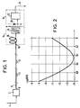
- Figure 1 shows an overview of a connection according to the present invention.
- FIG. 2 represents a diagram of variation of a transmission error rate as a function of a relative compensation deficit achieved on such a link.
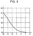
- FIG. 3 represents a diagram of variation of an optimal compensation deficit as a function of an average power.
- the link of FIG. 1 comprises various elements which, as regards the functions which will be indicated, are common to it with the first very long distance link previously mentioned.
- the correction means signal 14 further comprise a dispersion compensator 26 having a compensation dispersion of the same nature and opposite direction to that of the line dispersion, the absolute value of this compensation dispersion being less than that of this line dispersion, the difference of these two values constituting a compensation deficit which is chosen to be close to an optimal compensation deficit minimizing said error rate.
- This relative compensation deficit constituted by the compensation deficit related to the transmission dispersion.
- This relative compensation deficit is greater than 5% and preferably between 5 and 80%, the optimal value of this deficit being a function of the average power on the line, as shown in FIG. 3.
- the corrective filter bandwidth is between 0.2 and 0.9 nm and more preferably in the range 0.25 - 0.6 nm.
- the dispersion compensator is constituted by a dispersion compensation optical fiber having a compensating linear dispersion greater, in absolute values, than ten times the linear dispersion of line.
- the link which has just been described applies to the line output signal a processing method which can be applied with advantage whenever an optical signal carries information to be transmitted and has undergone nonlinear effects and dispersion.
- chromatic line According to this method, in order to collect this information with a minimum error rate, a chromatic compensation compensation is applied to this signal having a direction opposite to that of this line dispersion and a lower absolute value.
- the diagrams in Figures 2 and 3 were obtained by numerical simulation.
- the diagram in FIG. 2 shows on the abscissa a relative compensation deficit which can be applied to the output of such a line. It represents on the ordinate the logarithm of the resulting transmission error rate when this link includes amplifiers 50 km apart to provide an output power of -2.5 dBm corresponding to an average power of -6.6 dBm. It shows an optimal relative compensation deficit making this error rate minimal and close in this particular case to 0.45.
- the diagram in FIG. 3 represents the average power on such a line on the abscissa and the corresponding optimal compensation deficit on the ordinate.
Abstract
Description
La présente invention concerne la réalisation d'une liaison de communication optique lorsque des effets non linéaires affectent suffisamment la transmission d'informations par cette liaison pour nécessiter une correction de ces effets. Une telle liaison est typiquement une liaison à très grande distance telle que les liaisons intercontinentales dont les longueurs vont de 3 000 à 10 000 km environ et éventuellement plus.The present invention relates to the realization of an optical communication link when non-linear effects sufficiently affect the transmission of information by this link to require correction of these effects. Such a link is typically a very long distance link such as intercontinental links whose lengths range from 3,000 to 10,000 km approximately and possibly more.
Des liaisons de longueurs plus petites peuvent cependant être concernées par la présente invention si leurs puissances optiques moyennes sont importantes. Plus précisément cette invention s'applique lorsque l'intégrale de la puissance sur la longueur de la ligne : somme de P.dl, atteint des valeurs élevées faisant apparaître des effets non linéaires propres à créer des erreurs de transmission gênantes.Links of shorter lengths may however be concerned by the present invention if their average optical powers are large. More precisely, this invention applies when the integral of the power over the length of the line: sum of P.dl, reaches high values showing non-linear effects capable of creating annoying transmission errors.
Une telle liaison connue comporte des éléments qui sont communs à cette liaison et à une liaison selon la présente invention et qui comportent d'abord une ligne de transmission. Cette ligne est constituée d'une fibre optique de ligne présentant une dispersion linéique de nature chromatique de sens normal et inférieure à 1 et de préférence à 0,5 ps/nm.km de sorte que l'ensemble de cette ligne présente une dispersion de ligne qui déforme un signal transmis. Cette ligne est munie d'amplificateurs optiques répartis sur sa longueur de sorte qu'un signal optique guidé par cette fibre présente localement des amplitudes accrues faisant apparaître des effets non linéaires qui contribuent à déformer encore ce signal.Such a known link comprises elements which are common to this link and to a link according to the present invention and which first comprise a transmission line. This line consists of a line optical fiber having a linear dispersion of a chromatic nature of normal direction and less than 1 and preferably at 0.5 ps / nm.km so that the whole of this line has a dispersion of line that distorts a transmitted signal. This line is provided with optical amplifiers distributed over its length so that an optical signal guided by this fiber locally has increased amplitudes showing nonlinear effects which contribute to further distort this signal.
Ces éléments communs comportent encore des moyens de correction de signal optique pour recevoir le signal de sortie de ligne et pour le corriger de manière à obtenir un signal optique corrigé plus proche du signal d'entrée de ligne. Ces moyens de correction de signal comportent un filtre de sortie filtrant des fréquences optiques. Une largeur de bande passante de ce filtre constitue une largeur de bande de filtrage correctif.These common elements also include optical signal correction means for receiving the line output signal and for correcting it so as to obtain a corrected optical signal closer to the line input signal. These signal correction means include an output filter filtering optical frequencies. A bandwidth of this filter constitutes a corrective filtering bandwidth.
Ces éléments communs comportent enfin des moyens d'exploitation de signal optique pour recevoir le signal corrigé et pour en extraire une information à transmettre qui était portée par le signal d'entrée. Cette information est inévitablement extraite avec un taux d'erreur. La largeur de bande de filtrage correctif est choisie pour minimiser ce taux d'erreur.These common elements finally comprise optical signal processing means for receiving the corrected signal and for extracting therefrom information to be transmitted which was carried by the input signal. This information is inevitably extracted with an error rate. The corrective filter bandwidth is chosen to minimize this error rate.
Dans une première liaison à très grande distance connue, la largeur de bande de filtrage correctif est très petite. Il s'agit en effet d'éliminer autant que possible les composantes spectrales ajoutées par les effets non linéaires. Cette largeur est par exemple de 20 GHz c'est-à-dire de 0,16 nm.In a first known very long distance link, the corrective filter bandwidth is very small. It is indeed a question of eliminating as much as possible the spectral components added by the nonlinear effects. This width is for example 20 GHz, that is to say 0.16 nm.
Cette première liaison à très grande distance connue est proposée dans le Journal of lightwave technology, vol 9 n°3 Mars 1991. (D. Marcuse).This first known very long distance link is proposed in the Journal of lightwave technology,
Une deuxième liaison à très grande distance connue est décrite dans un article N.Henmi, et al."Dispersion compensation by prechirp technique in multigigabit optical amplifier repeater systems " (Topical Meeting on Optical Amplifiers and Their Applications" Août 1990).A second known very long distance link is described in an article by N. Henmi, et al. "Dispersion compensation by prechirp technique in multigigabit optical amplifier repeater systems" (Topical Meeting on Optical Amplifiers and Their Applications "August 1990).
La présente invention a notamment pour but de permettre de réaliser simplement une liaison de ce genre présentant un taux d'erreur diminué et/ou un débit de transmission augmenté.The object of the present invention is in particular to allow a connection of this kind to be produced simply with a reduced error rate and / or an increased transmission rate.
Dans ces buts elle propose de disposer, en sortis de la ligne de transmission, un compensateur de dispersion pour appliquer une dispersion de compensation de nature chromatique présentant un sens opposé à celui de la dispersion de ligne mais une valeur absolue inférieure faisant apparaître un déficit de compensation non nul. Elle a également pour objet un procédé de traitement de signal optique tel que celui qui est appliqué dans cette liaison.For these purposes, it proposes to have, at the end of the transmission line, a dispersion compensator for applying a compensation dispersion of chromatic nature having a direction opposite to that of the line dispersion but a lower absolute value showing a deficit of non-zero compensation. It also relates to an optical signal processing method such as that which is applied in this link.
Selon la présente invention certaines des composantes spectrales ajoutées par les effets non linéaires ne sont pas éliminées par le filtre de sortie comme dans la première liaison à très grande distance connue précédemment mentionnée. Grâce au compensateur de dispersion elles sont au contraire utilisées pour constituer un signal corrigé de qualité améliorée.According to the present invention, some of the spectral components added by the nonlinear effects are not eliminated by the output filter as in the first known very long distance link previously mentioned. Thanks to the dispersion compensator they are on the contrary used to constitute a corrected signal of improved quality.
On peut remarquer que l'utilisation d'un compensateur de dispersion constitué par une fibre optique en sortie d'une ligne de transmission a déjà été proposée par un article K.Hagimoto et al"A 17 Gb/s long-span fiber transmission experiment using a low noise broad-band receiver with optical amplification and equalization" (Topical Meeting on Optical Amplifiers and Their Applications" Août 1990.It can be noted that the use of a dispersion compensator constituted by an optical fiber at the output of a transmission line has already been proposed by an article K.Hagimoto et al "A 17 Gb / s long-span fiber transmission experiment using a low noise broad-band receiver with optical amplification and equalization "(Topical Meeting on Optical Amplifiers and Their Applications" August 1990.
Il s'agissait d'une liaison à distance modérée (150 km).It was a moderate distance link (150 km).
Dans une telle liaison à distance modérée les effets non linéaires sont négligeables et on utilise des fibres de ligne relativement peu coûteuses qui présentent des dispersions linéiques de ligne relativement élevées de l'ordre 1 ps/nm.km. Dans ces liaisons la distorsion du signal de sortie est donc une distorsion chromatique simple et il n'y a pratiquement pas de composantes spectrales ajoutées.In such a moderate distance link the non-linear effects are negligible and relatively inexpensive line fibers are used which have relatively high line linear dispersions of the order of 1 ps / nm.km. In these links the distortion of the output signal is therefore a simple chromatic distortion and there are practically no spectral components added.
A l'aide des figures schématiques ci-jointes on va décrire plus particulièrement ci-après, à titre d'exemple non limitatif, comment la présente invention peut être mise en oeuvre.Using the attached schematic figures, a more specific description will be given below, by way of non-limiting example, of how the present invention can be implemented.
La figure 1 représente une vue d'ensemble d'une liaison selon la présente invention.Figure 1 shows an overview of a connection according to the present invention.
La figure 2 représente un diagramme de variation d'un taux d'erreur de transmission en fonction d'un déficit de compensation relatif réalisé sur une telle liaison.FIG. 2 represents a diagram of variation of a transmission error rate as a function of a relative compensation deficit achieved on such a link.
La figure 3 représente un diagramme de variation d'un déficit de compensation optimal en fonction d'une puissance moyenne.FIG. 3 represents a diagram of variation of an optimal compensation deficit as a function of an average power.
La liaison de la figure 1 comporte divers éléments qui, quant aux fonctions qui vont être indiquées, lui sont communs avec la première liaison à très grande distance précédemment mentionnée.The link of FIG. 1 comprises various elements which, as regards the functions which will be indicated, are common to it with the first very long distance link previously mentioned.
Ces éléments communs sont les suivants :
- Des moyens d'émission 2 recevant un signal d'entrée de liaison de nature électrique par un conducteur électrique 4, et formant en réponse un signal d'entrée de ligne de nature optique portant une information à transmettre.
- Une ligne de
transmission 6 ayant uneentrée 8 pour recevoir ce signal d'entrée de ligne et unesortie 10 pour fournir un signal de sortie de ligne résultant de la transmission de ce signal d'entrée. Cette ligne a par exemple une longueur supérieure à 3 000 km. Elle est constituée d'une fibre optique de ligne présentant une dispersion linéique de nature chromatique de sens normal et inférieure par exemple à 0,5 ps/nm.km de sorte que l'ensemble de cette ligne présente une dispersion de ligne. Elle est munie d'amplificateurs optiques 12 répartis sur sa longueur de sorte qu'un signal optique guidé par cette fibre présente localement des amplitudes accrues faisant apparaître des effets non linéaires. Ces effets élargissent le spectre de ce signal par des composantes spectrales ajoutées. Il en résulte que le signal de sortie de ligne présente, par rapport au signal d'entrée de ligne, non seulement une distorsion chromatique simple résultant de l'effet de la dispersion de ligne sur ce signal d'entrée mais surtout une distorsion composite résultant de l'effet de la dispersion de ligne sur ces composantes spectrales ajoutées. - Des moyens de correction de signal optique 14 pour recevoir le signal de sortie de ligne et pour le traiter de manière à obtenir un signal optique corrigé plus proche du signal d'entrée de ligne. Ces moyens de correction de signal comportent un filtre de sortie 16 filtrant des fréquences optiques en présentant une largeur de bande passante qui constitue une largeur de bande de filtrage correctif.
- Des moyens d'exploitation de signal optique 18 pour recevoir ce signal corrigé et pour en extraire une information à transmettre qui était portée par le signal d'entrée. Cette information est extraite avec un taux d'erreur, ladite largeur de bande de filtrage correctif étant choisie pour minimiser ce taux d'erreur. Ces moyens d'exploitation de signal optique comportent un
détecteur 20 fournissant un signal détecté de nature électrique à des circuits électroniques d'exploitation 22 qui fournissent un signal de sortie de liaison sur une ligne électrique 24. C'est ce signal de sortie de liaison qui restitue l'information à transmettre et c'est sur lui que l'on mesure le taux d'erreur de la liaison.
- Emission means 2 receiving an electrical connection signal by an electrical conductor 4, and forming in response an optical line input signal carrying information to be transmitted.
- A
transmission line 6 having aninput 8 to receive this line input signal and anoutput 10 to provide a signal line output resulting from the transmission of this input signal. This line has for example a length greater than 3000 km. It is made up of a line optical fiber having a linear dispersion of a chromatic nature of normal direction and less than for example 0.5 ps / nm.km so that the whole of this line has a line dispersion. It is provided withoptical amplifiers 12 distributed over its length so that an optical signal guided by this fiber locally has increased amplitudes showing non-linear effects. These effects broaden the spectrum of this signal by adding spectral components. As a result, the line output signal presents, relative to the line input signal, not only a simple chromatic distortion resulting from the effect of line dispersion on this input signal but above all a composite distortion resulting the effect of line dispersion on these added spectral components. - Optical signal correction means 14 for receiving the line output signal and for processing it so as to obtain a corrected optical signal closer to the line input signal. These signal correction means comprise an output filter 16 filtering optical frequencies by having a bandwidth which constitutes a corrective filter bandwidth.
- Optical signal processing means 18 for receiving this corrected signal and for extracting from it information to be transmitted which was carried by the input signal. This information is extracted with an error rate, said corrective filtering bandwidth being chosen to minimize this error rate. These optical signal processing means comprise a
detector 20 providing a detected signal of an electrical nature toelectronic operating circuits 22 which supply a link output signal on an electrical line 24. It is this link output signal which restores the information to be transmitted and it is on it that we measure the link error rate.
Conformément à la présente invention les moyens de correction de signal 14 comportent en outre un compensateur de dispersion 26 présentant une dispersion de compensation de même nature et de sens opposé à celui de la dispersion de ligne, la valeur absolue de cette dispersion de compensation étant inférieure à celle de cette dispersion de ligne, la différence de ces deux valeurs constituant un déficit de compensation qui est choisi voisin d'un déficit de compensation optimal minimisant ledit taux d'erreur.In accordance with the present invention, the correction means
On peut définir un déficit de compensation relatif constitué par le déficit de compensation rapporté à la dispersion de transmission. Ce déficit de compensation relatif est supérieur à 5 % et de préférence compris entre 5 et 80 %, la valeur optimale de ce déficit étant fonction de la puissance moyenne sur la ligne, comme représenté à la figure 3.We can define a relative compensation deficit constituted by the compensation deficit related to the transmission dispersion. This relative compensation deficit is greater than 5% and preferably between 5 and 80%, the optimal value of this deficit being a function of the average power on the line, as shown in FIG. 3.
De préférence encore la largeur de bande de filtrage correctif est comprise entre 0,2 et 0,9 nm et de préférence encore dans l'intervalle 0,25 - 0,6 nm.More preferably, the corrective filter bandwidth is between 0.2 and 0.9 nm and more preferably in the range 0.25 - 0.6 nm.
De même que dans la liaison à distance moyenne connue précédemment mentionnée, et de préférence, le compensateur de dispersion est constitué par une fibre optique de compensation de dispersion présentant une dispersion linéïque de compensation supérieure, en valeurs absolues, à dix fois la dispersion linéïque de ligne.As in the previously mentioned known medium distance link, and preferably, the dispersion compensator is constituted by a dispersion compensation optical fiber having a compensating linear dispersion greater, in absolute values, than ten times the linear dispersion of line.
On comprendra que la liaison qui vient d'être décrite applique au signal de sortie de ligne un procédé de traitement qui peut être appliqué avec avantage chaque fois qu'un signal optique porte une information à transmettre et a subi des effets non linéaires et une dispersion de ligne de nature chromatique. Selon ce procédé, pour recueillir cette information avec un taux d'erreur minimal, on applique à ce signal une dispersion de compensation de nature chromatique présentant un sens opposé à celui de cette dispersion de ligne et une valeur absolue inférieure.It will be understood that the link which has just been described applies to the line output signal a processing method which can be applied with advantage whenever an optical signal carries information to be transmitted and has undergone nonlinear effects and dispersion. chromatic line. According to this method, in order to collect this information with a minimum error rate, a chromatic compensation compensation is applied to this signal having a direction opposite to that of this line dispersion and a lower absolute value.
Les diagrammes des figures 2 et 3 ont été obtenus par une simulation numérique. Le diagramme de la figure 2 représente en abscisses un déficit de compensation relatif pouvant être appliqué à la sortie d'une telle ligne. Il représente en ordonnées le logarithme du taux d'erreurs de transmission qui en résulte lorsque cette liaison comporte des amplificateurs distants de 50 km pour fournir une puissance de sortie de -2,5 dBm correspondant à une puissance moyenne de -6,6 dBm. Il fait apparaître un déficit de compensation relatif optimal rendant ce taux d'erreur minimal et voisin dans ce cas particulier de 0,45. Le diagramme de la figure 3 représente en abscisses la puissance moyenne sur une telle ligne et en ordonnées le déficit de compensation relatif optimal correspondant.The diagrams in Figures 2 and 3 were obtained by numerical simulation. The diagram in FIG. 2 shows on the abscissa a relative compensation deficit which can be applied to the output of such a line. It represents on the ordinate the logarithm of the resulting transmission error rate when this link includes amplifiers 50 km apart to provide an output power of -2.5 dBm corresponding to an average power of -6.6 dBm. It shows an optimal relative compensation deficit making this error rate minimal and close in this particular case to 0.45. The diagram in FIG. 3 represents the average power on such a line on the abscissa and the corresponding optimal compensation deficit on the ordinate.
Claims (9)
cette ligne étant munie d'amplificateurs optiques (12) répartis sur sa longueur de sorte qu'un signal optique guidé par cette fibre présente localement des amplitudes accrues faisant apparaître des effets non linéaires qui élargissent le spectre de ce signal par des composantes spectrales ajoutées, et que le signal de sortie de ligne présente, par rapport au signal d'entrée de ligne, non seulement une distorsion chromatique simple résultant de l'effet de la dispersion de ligne sur ce signal d'entrée mais surtout une distorsion composite résultant de l'effet de la dispersion de ligne sur ces composantes spectrales ajoutées,
cette ligne étant caractérisée par le fait que lesdits moyens de correction de signal (14) comportent en outre un compensateur de dispersion (26) présentant une dispersion de compensation de même nature et de sens opposé à celui de la dispersion de ligne, la valeur absolue de cette dispersion de compensation étant inférieure à celle de cette dispersion de ligne, la différence de ces deux valeurs constituant un déficit de compensation qui est choisi voisin d'un déficit de compensation optimal minimisant ledit taux d'erreur.
this line being provided with optical amplifiers (12) distributed over its length so that an optical signal guided by this fiber locally has increased amplitudes making nonlinear effects appear which widen the spectrum of this signal by added spectral components, and that the line output signal presents, with respect to the line input signal, not only a simple chromatic distortion resulting from the effect of line dispersion on this input signal but above all a composite distortion resulting from the effect of line dispersion on these added spectral components,
this line being characterized by the fact that said signal correction means (14) further comprises a dispersion compensator (26) having a compensation dispersion of the same nature and in the opposite direction to that of the line dispersion, the absolute value of this compensation dispersion being less than that of this line dispersion, the difference of these two values constituting a compensation deficit which is chosen to be close to an optimal compensation deficit minimizing said error rate.
Applications Claiming Priority (2)
| Application Number | Priority Date | Filing Date | Title |
|---|---|---|---|
| FR9111077A FR2681202B1 (en) | 1991-09-06 | 1991-09-06 | OPTICAL COMMUNICATION LINK WITH CORRECTION OF NON-LINEAR EFFECTS, AND METHOD FOR PROCESSING AN OPTICAL SIGNAL. |
| FR9111077 | 1991-09-06 |
Publications (2)
| Publication Number | Publication Date |
|---|---|
| EP0531210A1 true EP0531210A1 (en) | 1993-03-10 |
| EP0531210B1 EP0531210B1 (en) | 1998-03-04 |
Family
ID=9416731
Family Applications (1)
| Application Number | Title | Priority Date | Filing Date |
|---|---|---|---|
| EP92402401A Expired - Lifetime EP0531210B1 (en) | 1991-09-06 | 1992-09-03 | Optical communication link with non-linear effects correction and optical signal processing method |
Country Status (9)
| Country | Link |
|---|---|
| US (1) | US5355240A (en) |
| EP (1) | EP0531210B1 (en) |
| JP (1) | JP2711200B2 (en) |
| AU (1) | AU650161B2 (en) |
| CA (1) | CA2077481C (en) |
| DE (1) | DE69224569T2 (en) |
| ES (1) | ES2114922T3 (en) |
| FR (1) | FR2681202B1 (en) |
| NZ (1) | NZ244190A (en) |
Cited By (4)
| Publication number | Priority date | Publication date | Assignee | Title |
|---|---|---|---|---|
| GB2277651A (en) * | 1993-04-19 | 1994-11-02 | British Tech Group | Post transmission dispersion compensation of amplifier induced frequency jitter |
| US5365362A (en) * | 1993-09-10 | 1994-11-15 | At&T Bell Laboratories | Ultra-high capacity non-soliton optical transmission using optical phase conjugation |
| EP0626768A1 (en) * | 1993-05-28 | 1994-11-30 | AT&T Corp. | High capacity optical fiber network |
| FR2706225A1 (en) * | 1993-06-07 | 1994-12-16 | Mitsubishi Electric Corp | Fibre-optic telecommunications device |
Families Citing this family (33)
| Publication number | Priority date | Publication date | Assignee | Title |
|---|---|---|---|---|
| FR2681145A1 (en) * | 1991-09-06 | 1993-03-12 | Alcatel Cable | LARGE DISTANCE OPTICAL COMMUNICATION LINE AND METHOD FOR PRODUCING THE SAME |
| JP2760233B2 (en) * | 1992-09-29 | 1998-05-28 | 住友電気工業株式会社 | Optical communication device |
| FR2700901B1 (en) * | 1993-01-28 | 1995-02-24 | Alcatel Nv | Soliton transmission system and method. |
| FR2707442B1 (en) * | 1993-07-06 | 1995-09-15 | Pirio Francis | Transmission system on optical fiber with compensation for online distortions. |
| EP0684709B1 (en) * | 1994-05-25 | 2002-10-02 | AT&T Corp. | Optical communications system with adjustable dispersion compensation |
| US5539563A (en) * | 1994-05-31 | 1996-07-23 | At&T Corp. | System and method for simultaneously compensating for chromatic dispersion and self phase modulation in optical fibers |
| JP3846918B2 (en) * | 1994-08-02 | 2006-11-15 | 富士通株式会社 | Optical transmission system, optical multiplex transmission system and related technologies |
| JP3373333B2 (en) * | 1994-09-12 | 2003-02-04 | Kddi株式会社 | Optical amplification repeater transmission system |
| GB9524203D0 (en) | 1995-11-27 | 1996-01-31 | British Tech Group | Optical communications |
| US5940208A (en) * | 1996-04-02 | 1999-08-17 | Corning Incorporated | Switchable fiber optic device for fiber transmission system and components thereof |
| JP3522044B2 (en) * | 1996-04-19 | 2004-04-26 | 富士通株式会社 | Optical transmission system |
| JP3748652B2 (en) * | 1997-02-27 | 2006-02-22 | 富士通株式会社 | Optical transmission system using inline amplifier |
| JPH10242909A (en) | 1997-02-27 | 1998-09-11 | Fujitsu Ltd | Optical transmission system |
| US6191854B1 (en) | 1997-06-23 | 2001-02-20 | Pirelli Cavi E Sistemi S.P.A. | Optical telecommunications system |
| US6496300B2 (en) | 1998-02-27 | 2002-12-17 | Fujitsu Limited | Optical amplifier |
| US6441955B1 (en) | 1998-02-27 | 2002-08-27 | Fujitsu Limited | Light wavelength-multiplexing systems |
| EP1294114A4 (en) * | 2000-05-22 | 2006-07-19 | Sumitomo Electric Industries | Wdm transmission system |
| US7173551B2 (en) | 2000-12-21 | 2007-02-06 | Quellan, Inc. | Increasing data throughput in optical fiber transmission systems |
| US7149256B2 (en) | 2001-03-29 | 2006-12-12 | Quellan, Inc. | Multilevel pulse position modulation for efficient fiber optic communication |
| US7307569B2 (en) | 2001-03-29 | 2007-12-11 | Quellan, Inc. | Increasing data throughput in optical fiber transmission systems |
| US7215721B2 (en) | 2001-04-04 | 2007-05-08 | Quellan, Inc. | Method and system for decoding multilevel signals |
| AU2003211094A1 (en) | 2002-02-15 | 2003-09-09 | Quellan, Inc. | Multi-level signal clock recovery technique |
| US6816101B2 (en) | 2002-03-08 | 2004-11-09 | Quelian, Inc. | High-speed analog-to-digital converter using a unique gray code |
| AU2003256569A1 (en) | 2002-07-15 | 2004-02-02 | Quellan, Inc. | Adaptive noise filtering and equalization |
| US7934144B2 (en) | 2002-11-12 | 2011-04-26 | Quellan, Inc. | High-speed analog-to-digital conversion with improved robustness to timing uncertainty |
| DE60208651T2 (en) * | 2002-11-15 | 2006-08-10 | Alcatel | Digital signal processing receiver and method for its operation |
| DE112004001455B4 (en) | 2003-08-07 | 2020-04-23 | Intersil Americas LLC | Cross-talk cancellation method and system |
| US7804760B2 (en) | 2003-08-07 | 2010-09-28 | Quellan, Inc. | Method and system for signal emulation |
| JP4510832B2 (en) | 2003-11-17 | 2010-07-28 | ケラン インコーポレイテッド | Method and system for antenna interference cancellation |
| US7616700B2 (en) | 2003-12-22 | 2009-11-10 | Quellan, Inc. | Method and system for slicing a communication signal |
| US7522883B2 (en) | 2004-12-14 | 2009-04-21 | Quellan, Inc. | Method and system for reducing signal interference |
| US7725079B2 (en) | 2004-12-14 | 2010-05-25 | Quellan, Inc. | Method and system for automatic control in an interference cancellation device |
| KR101372361B1 (en) | 2006-04-26 | 2014-03-12 | 인터실 아메리카스 엘엘씨 | Method and system for reducing radiated emissions from a communications channel |
Citations (1)
| Publication number | Priority date | Publication date | Assignee | Title |
|---|---|---|---|---|
| US4969710A (en) * | 1988-04-08 | 1990-11-13 | Corning Incorporated | Optical fiber transmission path with dispersion compensation |
Family Cites Families (9)
| Publication number | Priority date | Publication date | Assignee | Title |
|---|---|---|---|---|
| JPS6265529A (en) * | 1985-09-17 | 1987-03-24 | Hitachi Cable Ltd | Decentralization compensation method for optical communication system |
| JPS6265530A (en) * | 1985-09-17 | 1987-03-24 | Hitachi Cable Ltd | Optical transmission system |
| JPS62178220A (en) * | 1986-01-31 | 1987-08-05 | Nec Corp | Optical transmission line |
| US4947134A (en) * | 1987-10-30 | 1990-08-07 | American Telephone And Telegraph Company | Lightwave systems using optical amplifiers |
| JP2522331B2 (en) * | 1987-11-16 | 1996-08-07 | 日本電気株式会社 | Optical transmission line |
| US5055795A (en) * | 1990-05-29 | 1991-10-08 | At&T Bell Laboratories | Traveling wave type transversal equalizer |
| DE69133133T2 (en) * | 1990-07-13 | 2003-02-06 | Nec Corp | Intensity modulated optical transmission device |
| US5218662A (en) * | 1992-05-06 | 1993-06-08 | Alcatel Network Systems, Inc. | Fiber-optic cable system and method for dispersion compensation at nodes between end points |
| US5224183A (en) * | 1992-07-23 | 1993-06-29 | Alcatel Network Systems, Inc. | Multiple wavelength division multiplexing signal compensation system and method using same |
-
1991
- 1991-09-06 FR FR9111077A patent/FR2681202B1/en not_active Expired - Fee Related
-
1992
- 1992-09-01 US US07/937,698 patent/US5355240A/en not_active Expired - Lifetime
- 1992-09-02 NZ NZ244190A patent/NZ244190A/en unknown
- 1992-09-03 EP EP92402401A patent/EP0531210B1/en not_active Expired - Lifetime
- 1992-09-03 ES ES92402401T patent/ES2114922T3/en not_active Expired - Lifetime
- 1992-09-03 CA CA002077481A patent/CA2077481C/en not_active Expired - Fee Related
- 1992-09-03 DE DE69224569T patent/DE69224569T2/en not_active Expired - Lifetime
- 1992-09-03 AU AU22074/92A patent/AU650161B2/en not_active Ceased
- 1992-09-04 JP JP4237074A patent/JP2711200B2/en not_active Expired - Fee Related
Patent Citations (1)
| Publication number | Priority date | Publication date | Assignee | Title |
|---|---|---|---|---|
| US4969710A (en) * | 1988-04-08 | 1990-11-13 | Corning Incorporated | Optical fiber transmission path with dispersion compensation |
Non-Patent Citations (4)
| Title |
|---|
| IEEE JOURNAL OF QUANTUM ELECTRONICS. vol. 25, no. 9, Septembre 1989, NEW YORK US pages 1981 - 1984 A.FRENKEL ET AL 'Compensation of dispersion in Optical Fibers for the 1.3-1.6 micrometer Region with a Grating and Telescope' * |
| IEEE PHOTONICS TECHNOLOGY LETTERS vol. 2, no. 8, Août 1990, NEW YORK, US pages 585 - 587 A.H.GNAUCK ET AL 'Optical Equalization of Fiber Chromatic Dispersion in a 5-Gb/s Transmission System' * |
| JOURNAL OF LIGHTWAVE TECHNOLOGY. vol. 8, no. 3, Mars 1990, NEW YORK US pages 367 - 375 K.IWASHITA ET AL 'Chromatic Dispersion Compensation in Coherent Optical Communications' * |
| PATENT ABSTRACTS OF JAPAN vol. 11, no. 257 (E-534)(2704) 20 Août 1987 & JP-A-62 065 530 ( HITACHI CABLE LTD ) * |
Cited By (8)
| Publication number | Priority date | Publication date | Assignee | Title |
|---|---|---|---|---|
| GB2277651A (en) * | 1993-04-19 | 1994-11-02 | British Tech Group | Post transmission dispersion compensation of amplifier induced frequency jitter |
| GB2277651B (en) * | 1993-04-19 | 1997-12-10 | British Tech Group | Optical communications |
| EP0626768A1 (en) * | 1993-05-28 | 1994-11-30 | AT&T Corp. | High capacity optical fiber network |
| US5587830A (en) * | 1993-05-28 | 1996-12-24 | Lucent Technologies Inc. | High capacity optical fiber network |
| US5719696A (en) * | 1993-05-28 | 1998-02-17 | Lucent Technologies Inc. | High capacity optical fiber network |
| FR2706225A1 (en) * | 1993-06-07 | 1994-12-16 | Mitsubishi Electric Corp | Fibre-optic telecommunications device |
| US5519528A (en) * | 1993-06-07 | 1996-05-21 | Mitsubishi Denki Kabushiki Kaisha | Method of optical fiber communication |
| US5365362A (en) * | 1993-09-10 | 1994-11-15 | At&T Bell Laboratories | Ultra-high capacity non-soliton optical transmission using optical phase conjugation |
Also Published As
| Publication number | Publication date |
|---|---|
| CA2077481A1 (en) | 1993-03-07 |
| AU650161B2 (en) | 1994-06-09 |
| FR2681202B1 (en) | 1993-11-12 |
| FR2681202A1 (en) | 1993-03-12 |
| JPH05204004A (en) | 1993-08-13 |
| DE69224569T2 (en) | 1998-06-25 |
| AU2207492A (en) | 1993-03-11 |
| ES2114922T3 (en) | 1998-06-16 |
| US5355240A (en) | 1994-10-11 |
| EP0531210B1 (en) | 1998-03-04 |
| JP2711200B2 (en) | 1998-02-10 |
| DE69224569D1 (en) | 1998-04-09 |
| CA2077481C (en) | 1996-10-01 |
| NZ244190A (en) | 1995-06-27 |
Similar Documents
| Publication | Publication Date | Title |
|---|---|---|
| CA2077481C (en) | Non linear effect correction optical communication line and light signal processing method | |
| FR2685835A1 (en) | VERY LONG DISTANCE TRANSMISSION SYSTEM ON OPTICAL FIBER COMPENSATED FOR DISTORTIONS AT RECEPTION. | |
| FR2768233A1 (en) | Optical transmission compensator | |
| FR2908250A1 (en) | COMPENSATION FIBER OF CHROMATIC DISPERSION | |
| EP0562953A1 (en) | Optical filter containing a Fabry-Perot interferometer tunable by rotation | |
| CA2177221C (en) | Process for incorporating binary data to a carrier wave, particularly a light wave, and transmission system using said process | |
| CA2166178A1 (en) | Filter for guided light and optical link including said filter | |
| FR2799068A1 (en) | High capacity wavelength multiplexing optical transmission system dispersion compensation having signal input separator inputting and dispersion compensation/faraday rotator sent with returned signal passing through compensator/third port | |
| FR2815418A1 (en) | Optical fibre for chromatic dispersion compensation, uses rectangular profile step index with slice to provide negative chromatic dispersion | |
| EP1030474B1 (en) | Transmission line and method of transmission using optical fibres | |
| EP0532388A1 (en) | Long distance optical communication line and method of making the same | |
| CA2103178C (en) | Optical transmission system, particularly for a videocommunication cable network | |
| EP1213595B1 (en) | Chromatic dispersion compensation in a fiber transmission system and compensation fiber | |
| EP1312950B1 (en) | Chromatic dispersion compensating fibre for fibre optic transmission system in U band | |
| CA2200224A1 (en) | Optical soliton transmission process and system | |
| FR2706638A1 (en) | Chromatic time dispersion method, dispersive optical device, and optical fiber transmission system using the device | |
| EP1291685B1 (en) | Optical fibre with continuously varying chromatic dispersion | |
| EP1361685A1 (en) | Accumulated chromatic dispersion compensation fibre in a negative chromatic dispersion fibre | |
| EP1311079B1 (en) | Phase controlled optical signal transmission system | |
| EP1288682B1 (en) | Optical fiber for wavelength division multiplexing system | |
| WO2024002925A1 (en) | Method and device for optical finite impulse response filtering and corresponding optical equipment | |
| FR2862453A1 (en) | CHROMATIC DISPERSION COMPENSATION MODULE | |
| FR2757720A1 (en) | Optical terminal adaptor manufacturing method | |
| CA2256174A1 (en) | Optical amplifier with gain optimizable as a function of input power | |
| EP1011216A1 (en) | Optical fiber transmission system including a reception filter with tunable bandwidth |
Legal Events
| Date | Code | Title | Description |
|---|---|---|---|
| PUAI | Public reference made under article 153(3) epc to a published international application that has entered the european phase |
Free format text: ORIGINAL CODE: 0009012 |
|
| AK | Designated contracting states |
Kind code of ref document: A1 Designated state(s): DE ES FR GB IT |
|
| 17P | Request for examination filed |
Effective date: 19930705 |
|
| 17Q | First examination report despatched |
Effective date: 19961212 |
|
| GRAG | Despatch of communication of intention to grant |
Free format text: ORIGINAL CODE: EPIDOS AGRA |
|
| GRAG | Despatch of communication of intention to grant |
Free format text: ORIGINAL CODE: EPIDOS AGRA |
|
| GRAH | Despatch of communication of intention to grant a patent |
Free format text: ORIGINAL CODE: EPIDOS IGRA |
|
| GRAH | Despatch of communication of intention to grant a patent |
Free format text: ORIGINAL CODE: EPIDOS IGRA |
|
| RAP1 | Party data changed (applicant data changed or rights of an application transferred) |
Owner name: ALCATEL ALSTHOM COMPAGNIE GENERALE D'ELECTRICITE |
|
| GRAA | (expected) grant |
Free format text: ORIGINAL CODE: 0009210 |
|
| AK | Designated contracting states |
Kind code of ref document: B1 Designated state(s): DE ES FR GB IT |
|
| ITF | It: translation for a ep patent filed |
Owner name: JACOBACCI & PERANI S.P.A. |
|
| GBT | Gb: translation of ep patent filed (gb section 77(6)(a)/1977) |
Effective date: 19980305 |
|
| REF | Corresponds to: |
Ref document number: 69224569 Country of ref document: DE Date of ref document: 19980409 |
|
| REG | Reference to a national code |
Ref country code: ES Ref legal event code: FG2A Ref document number: 2114922 Country of ref document: ES Kind code of ref document: T3 |
|
| PLBE | No opposition filed within time limit |
Free format text: ORIGINAL CODE: 0009261 |
|
| STAA | Information on the status of an ep patent application or granted ep patent |
Free format text: STATUS: NO OPPOSITION FILED WITHIN TIME LIMIT |
|
| 26N | No opposition filed | ||
| RAP4 | Party data changed (patent owner data changed or rights of a patent transferred) |
Owner name: ALCATEL |
|
| PGFP | Annual fee paid to national office [announced via postgrant information from national office to epo] |
Ref country code: ES Payment date: 19990917 Year of fee payment: 8 |
|
| REG | Reference to a national code |
Ref country code: FR Ref legal event code: CD |
|
| PG25 | Lapsed in a contracting state [announced via postgrant information from national office to epo] |
Ref country code: ES Free format text: LAPSE BECAUSE OF NON-PAYMENT OF DUE FEES Effective date: 20000904 |
|
| REG | Reference to a national code |
Ref country code: GB Ref legal event code: IF02 |
|
| REG | Reference to a national code |
Ref country code: ES Ref legal event code: FD2A Effective date: 20011011 |
|
| REG | Reference to a national code |
Ref country code: FR Ref legal event code: CD |
|
| PGFP | Annual fee paid to national office [announced via postgrant information from national office to epo] |
Ref country code: IT Payment date: 20100927 Year of fee payment: 19 |
|
| PGFP | Annual fee paid to national office [announced via postgrant information from national office to epo] |
Ref country code: FR Payment date: 20110928 Year of fee payment: 20 Ref country code: DE Payment date: 20110923 Year of fee payment: 20 Ref country code: GB Payment date: 20110920 Year of fee payment: 20 |
|
| REG | Reference to a national code |
Ref country code: DE Ref legal event code: R071 Ref document number: 69224569 Country of ref document: DE |
|
| REG | Reference to a national code |
Ref country code: DE Ref legal event code: R071 Ref document number: 69224569 Country of ref document: DE |
|
| REG | Reference to a national code |
Ref country code: GB Ref legal event code: PE20 Expiry date: 20120902 |
|
| PG25 | Lapsed in a contracting state [announced via postgrant information from national office to epo] |
Ref country code: DE Free format text: LAPSE BECAUSE OF EXPIRATION OF PROTECTION Effective date: 20120904 Ref country code: GB Free format text: LAPSE BECAUSE OF EXPIRATION OF PROTECTION Effective date: 20120902 |