EP0530301B1 - Method and apparatus for depositing moisture-absorbent and thermoplastic material in a substrate - Google Patents
Method and apparatus for depositing moisture-absorbent and thermoplastic material in a substrate Download PDFInfo
- Publication number
- EP0530301B1 EP0530301B1 EP91910503A EP91910503A EP0530301B1 EP 0530301 B1 EP0530301 B1 EP 0530301B1 EP 91910503 A EP91910503 A EP 91910503A EP 91910503 A EP91910503 A EP 91910503A EP 0530301 B1 EP0530301 B1 EP 0530301B1
- Authority
- EP
- European Patent Office
- Prior art keywords
- pad
- moisture
- thermoplastic
- fibrous material
- thermoplastic fibers
- Prior art date
- Legal status (The legal status is an assumption and is not a legal conclusion. Google has not performed a legal analysis and makes no representation as to the accuracy of the status listed.)
- Expired - Lifetime
Links
- 239000012815 thermoplastic material Substances 0.000 title claims abstract description 45
- 238000000034 method Methods 0.000 title claims abstract description 38
- 239000002250 absorbent Substances 0.000 title abstract description 134
- 239000000758 substrate Substances 0.000 title description 4
- 238000000151 deposition Methods 0.000 title description 3
- 239000000463 material Substances 0.000 claims abstract description 137
- 239000002657 fibrous material Substances 0.000 claims abstract description 134
- 229920001169 thermoplastic Polymers 0.000 claims abstract description 121
- 239000004416 thermosoftening plastic Substances 0.000 claims abstract description 121
- 239000000835 fiber Substances 0.000 claims description 121
- 239000000126 substance Substances 0.000 claims description 13
- 239000000203 mixture Substances 0.000 claims description 7
- 230000000284 resting effect Effects 0.000 claims description 7
- 239000002245 particle Substances 0.000 abstract description 51
- 239000000853 adhesive Substances 0.000 description 45
- 230000001070 adhesive effect Effects 0.000 description 45
- 239000007921 spray Substances 0.000 description 44
- 239000004094 surface-active agent Substances 0.000 description 35
- 239000004831 Hot glue Substances 0.000 description 16
- 239000011230 binding agent Substances 0.000 description 15
- 230000002745 absorbent Effects 0.000 description 9
- 239000012943 hotmelt Substances 0.000 description 8
- 239000011236 particulate material Substances 0.000 description 8
- 230000005012 migration Effects 0.000 description 7
- 238000013508 migration Methods 0.000 description 7
- -1 polyethylene Polymers 0.000 description 6
- 239000012530 fluid Substances 0.000 description 5
- 239000004952 Polyamide Substances 0.000 description 4
- 229920001131 Pulp (paper) Polymers 0.000 description 4
- 229920002678 cellulose Polymers 0.000 description 4
- 239000001913 cellulose Substances 0.000 description 4
- 229920002647 polyamide Polymers 0.000 description 4
- 238000011144 upstream manufacturing Methods 0.000 description 4
- 239000004698 Polyethylene Substances 0.000 description 3
- 210000001124 body fluid Anatomy 0.000 description 3
- 239000010839 body fluid Substances 0.000 description 3
- 238000004519 manufacturing process Methods 0.000 description 3
- 229920000573 polyethylene Polymers 0.000 description 3
- 230000000717 retained effect Effects 0.000 description 3
- 238000010521 absorption reaction Methods 0.000 description 2
- 230000015572 biosynthetic process Effects 0.000 description 2
- 238000001125 extrusion Methods 0.000 description 2
- 229920000642 polymer Polymers 0.000 description 2
- 239000000843 powder Substances 0.000 description 2
- 239000004753 textile Substances 0.000 description 2
- 239000002699 waste material Substances 0.000 description 2
- XLYOFNOQVPJJNP-UHFFFAOYSA-N water Substances O XLYOFNOQVPJJNP-UHFFFAOYSA-N 0.000 description 2
- VBICKXHEKHSIBG-UHFFFAOYSA-N 1-monostearoylglycerol Chemical class CCCCCCCCCCCCCCCCCC(=O)OCC(O)CO VBICKXHEKHSIBG-UHFFFAOYSA-N 0.000 description 1
- 229920000742 Cotton Polymers 0.000 description 1
- 206010021639 Incontinence Diseases 0.000 description 1
- 239000002202 Polyethylene glycol Substances 0.000 description 1
- 239000004743 Polypropylene Substances 0.000 description 1
- 229920000180 alkyd Polymers 0.000 description 1
- 230000004888 barrier function Effects 0.000 description 1
- 239000011248 coating agent Substances 0.000 description 1
- 238000000576 coating method Methods 0.000 description 1
- 230000006835 compression Effects 0.000 description 1
- 238000007906 compression Methods 0.000 description 1
- 238000011109 contamination Methods 0.000 description 1
- 230000008878 coupling Effects 0.000 description 1
- 238000010168 coupling process Methods 0.000 description 1
- 238000005859 coupling reaction Methods 0.000 description 1
- 235000014113 dietary fatty acids Nutrition 0.000 description 1
- ZBCBWPMODOFKDW-UHFFFAOYSA-N diethanolamine Chemical class OCCNCCO ZBCBWPMODOFKDW-UHFFFAOYSA-N 0.000 description 1
- 230000007613 environmental effect Effects 0.000 description 1
- 239000004744 fabric Substances 0.000 description 1
- 239000000194 fatty acid Substances 0.000 description 1
- 229930195729 fatty acid Natural products 0.000 description 1
- 238000001914 filtration Methods 0.000 description 1
- 239000008187 granular material Substances 0.000 description 1
- 239000007788 liquid Substances 0.000 description 1
- 238000004806 packaging method and process Methods 0.000 description 1
- 150000003014 phosphoric acid esters Chemical class 0.000 description 1
- 239000004014 plasticizer Substances 0.000 description 1
- 229920000570 polyether Polymers 0.000 description 1
- 229920001223 polyethylene glycol Polymers 0.000 description 1
- 229920001155 polypropylene Polymers 0.000 description 1
- 230000008569 process Effects 0.000 description 1
- 230000004044 response Effects 0.000 description 1
- 229920006395 saturated elastomer Polymers 0.000 description 1
- 150000003467 sulfuric acid derivatives Chemical class 0.000 description 1
Images



Classifications
-
- D—TEXTILES; PAPER
- D04—BRAIDING; LACE-MAKING; KNITTING; TRIMMINGS; NON-WOVEN FABRICS
- D04H—MAKING TEXTILE FABRICS, e.g. FROM FIBRES OR FILAMENTARY MATERIAL; FABRICS MADE BY SUCH PROCESSES OR APPARATUS, e.g. FELTS, NON-WOVEN FABRICS; COTTON-WOOL; WADDING ; NON-WOVEN FABRICS FROM STAPLE FIBRES, FILAMENTS OR YARNS, BONDED WITH AT LEAST ONE WEB-LIKE MATERIAL DURING THEIR CONSOLIDATION
- D04H1/00—Non-woven fabrics formed wholly or mainly of staple fibres or like relatively short fibres
- D04H1/40—Non-woven fabrics formed wholly or mainly of staple fibres or like relatively short fibres from fleeces or layers composed of fibres without existing or potential cohesive properties
- D04H1/54—Non-woven fabrics formed wholly or mainly of staple fibres or like relatively short fibres from fleeces or layers composed of fibres without existing or potential cohesive properties by welding together the fibres, e.g. by partially melting or dissolving
-
- A—HUMAN NECESSITIES
- A61—MEDICAL OR VETERINARY SCIENCE; HYGIENE
- A61F—FILTERS IMPLANTABLE INTO BLOOD VESSELS; PROSTHESES; DEVICES PROVIDING PATENCY TO, OR PREVENTING COLLAPSING OF, TUBULAR STRUCTURES OF THE BODY, e.g. STENTS; ORTHOPAEDIC, NURSING OR CONTRACEPTIVE DEVICES; FOMENTATION; TREATMENT OR PROTECTION OF EYES OR EARS; BANDAGES, DRESSINGS OR ABSORBENT PADS; FIRST-AID KITS
- A61F13/00—Bandages or dressings; Absorbent pads
- A61F13/15—Absorbent pads, e.g. sanitary towels, swabs or tampons for external or internal application to the body; Supporting or fastening means therefor; Tampon applicators
- A61F13/15577—Apparatus or processes for manufacturing
- A61F13/15617—Making absorbent pads from fibres or pulverulent material with or without treatment of the fibres
- A61F13/15658—Forming continuous, e.g. composite, fibrous webs, e.g. involving the application of pulverulent material on parts thereof
-
- A—HUMAN NECESSITIES
- A61—MEDICAL OR VETERINARY SCIENCE; HYGIENE
- A61F—FILTERS IMPLANTABLE INTO BLOOD VESSELS; PROSTHESES; DEVICES PROVIDING PATENCY TO, OR PREVENTING COLLAPSING OF, TUBULAR STRUCTURES OF THE BODY, e.g. STENTS; ORTHOPAEDIC, NURSING OR CONTRACEPTIVE DEVICES; FOMENTATION; TREATMENT OR PROTECTION OF EYES OR EARS; BANDAGES, DRESSINGS OR ABSORBENT PADS; FIRST-AID KITS
- A61F13/00—Bandages or dressings; Absorbent pads
- A61F13/15—Absorbent pads, e.g. sanitary towels, swabs or tampons for external or internal application to the body; Supporting or fastening means therefor; Tampon applicators
- A61F13/53—Absorbent pads, e.g. sanitary towels, swabs or tampons for external or internal application to the body; Supporting or fastening means therefor; Tampon applicators characterised by the absorbing medium
- A61F13/534—Absorbent pads, e.g. sanitary towels, swabs or tampons for external or internal application to the body; Supporting or fastening means therefor; Tampon applicators characterised by the absorbing medium having an inhomogeneous composition through the thickness of the pad
- A61F13/535—Absorbent pads, e.g. sanitary towels, swabs or tampons for external or internal application to the body; Supporting or fastening means therefor; Tampon applicators characterised by the absorbing medium having an inhomogeneous composition through the thickness of the pad inhomogeneous in the plane of the pad, e.g. core absorbent layers being of different sizes
Definitions
- This invention relates to a method and apparatus for making moisture-absorbent substrates, and, more particularly, to a method and apparatus for interspersing highly moisture-absorbent particles and thermoplastic hot melt adhesive material throughout predetermined portions of a fibrous material pad in a non-woven product.
- Hygienic articles such as disposable diapers, sanitary napkins, incontinence pads and sick bed sheets must have a high moisture absorption capacity to effectively retain eliminated body fluids for acceptable periods of time.
- Early hygienic articles of this type employed cellulose wadding, fluff cellulose or absorbent cotton as the absorbent materials.
- One problem with these materials is that their moisture-retaining capacity is relatively small compared to their volume.
- the volume of such absorbent materials in the hygienic article must be increased. This produces a bulky product which is unacceptable in many hygienic articles, particularly sanitary napkins.
- one layer of such articles comprises a non-woven pad formed of cellulose fluff, wood pulp, textile fibers or other non-woven fibrous materials in which highly moisture-absorbent material is combined within the fiber structure of the pad.
- These highly moisture-absorbent materials are preferably water-insoluble absorbent polymers having a high capacity for absorbing water and body fluids, which are partially or wholly synthetic and are commercially available in fine-grain, particulate form. See, for example, U.S. Patent Nos. 3,997,484; 3,661,815; 4,117,222; and, 3,936,441.
- U.S. Patent No. 3,984,272 One system for forming the non-woven fibrous materials into a non-woven pad is disclosed in U.S. Patent No. 3,984,272.
- a forming chamber having an inlet and outlet is connected by a feed conduit to a source of fibrous materials such as finely ground wood pulp.
- a perforated conveyor is movable through the forming chamber between its inlet and outlet, and structure is provided to draw a vacuum on one side of the perforated conveyor.
- the fibrous material introduced into the chamber is drawn onto the opposite side of the conveyor by the vacuum, and this fibrous material forms a non-woven pad on the conveyor which increases in thickness in a direction from the inlet of the chamber toward its outlet.
- the non-woven pad thus has a bottom surface resting atop the conveyor and a top surface which angles or slopes upwardly relative to the conveyor from the inlet of the chamber toward its outlet.
- a leveling or scarfing roller near the outlet of the forming chamber is operative to remove at least a portion of the fibrous material at the top of the non-woven pad to produce a non-woven pad of uniform thickness.
- the pad is then transmitted by the conveyor through the outlet of the forming chamber for subsequent operations to form the completed hygienic article.
- the highly moisture-absorbent material is injected into the same feed conduit which supplies the fibrous material into the interior of the chamber.
- the highly moisture-absorbent material and fibrous material are intermixed within the feed conduit to completely intersperse the moisture-absorbent material throughout the fibers prior to introduction into the forming chamber. This produces a non-woven pad atop the conveyor within the chamber in which the moisture-absorbent material is present throughout the entire thickness, width and length of the non-woven pad.
- moisture-absorbent material is distributed throughout the non-woven pad across its entire length, width and thickness. This produces substantial waste because in subsequent forming operations, the non-woven pad is cut to the desired length of the hygienic article.
- the application of moisture-absorbent material across the entire width of the non-woven pad may be unnecessary for some types of hygienic articles, particularly disposable diapers where the leg holes are cut at the edges of the layer.
- Another method of combining moisture-absorbent material with the non-woven pads employed in hygienic articles involves the application of moisture-absorbent material onto the top surface of the non-woven pad downstream from the leveling or scarfing rollers and outside of the forming chamber. Accordingly, a non-woven pad is produced having moisture-absorbent material concentrated on its top surface with substantially no moisture-absorbent material within the remaining thickness of the pad.
- One disadvantage of this second method relates to the handling and loss of the moisture-absorbent material applied to the pad. Because the application of moisture-absorbent material takes place outside of the forming chamber in this method, a relatively expensive collection system is required to capture the oversprayed moisture-absorbent material and prevent it from escaping to the environment. Migration of the moisture-absorbent material out of the pad is a particular problem in this method because all of the powder is concentrated at its top surface. In particulate or granular form, the moisture-absorbent material can be readily dislodged from the type of pads which are not sealed at the ends.
- Another problem with this second method of incorporating the highly moisture-absorbent material into the non-woven pad is that the material is concentrated on top of the pad. This causes so-called “gel blockage” wherein the moisture-absorbent material at the top of the non-woven pad become saturated with fluid and prevents the wicking or transfer of moisture to the fibrous material in the remaining portion of the pad. As a result, the fluid is retained at the surface of the pad in contact with the wearer of the hygienic article causing discomfort. Additionally, only a relatively small portion of the entire thickness of the pad is effectively employed to absorb the moisture.
- US-A-4,927,346 entitled “Apparatus For Depositing Moisture-Absorbent Material In A Substrate", which is commonly owned by the assignee of the instant application.
- the apparatus disclosed in US-A-4,927,346 employs essentially the same type of forming chamber disclosed in Patent No. 3,984,272, but is effective to intermix highly moisture-absorbent material with fibrous material in a predetermined portion of the thickness of the pad and, if desired, at longitudinally spaced locations therealong.
- a dispenser such as a spray gun, is located at least partially within the forming chamber at a predetermined location with respect to the upwardly sloping top surface of the non-woven pad of fibrous material being drawn onto the conveyor.
- the dispenser is effective to intermix highly moisture-absorbent material with a portion of the fibrous material being drawn onto the conveyor at such predetermined location. This forms a layer of intermixed fibrous material and particulate material within a predetermined portion of the thickness of the pad while maintaining another portion of the thickness of the non-woven pad substantially free of particulate material.
- the apparatus disclosed in US-A-4,927,346 forms a non-woven pad in which fibrous material is drawn onto the conveyor beginning at the inlet to the forming chamber, and such fibrous material begins to build up on the conveyor between the inlet and the location of the spray gun for the highly moisture-absorbent material.
- This forms a bottom layer of the non-woven pad resting directly on the conveyor which increases in thickness in the direction of movement of the conveyor through the chamber.
- the spray gun intermixes a second material, e.g., highly moisture-absorbent particulate material, with the fibrous material being drawn onto the conveyor at the predetermined location where the spray gun is positioned at least partially within the forming chamber.
- This intermixture of fibrous material and particulate material forms an intermediate layer which is drawn onto the bottom layer of fibrous material already accumulated on the conveyor upstream from the location of the spray gun.
- additional fibrous material is drawn toward the conveyor forming a top layer of fibrous material over the intermediate layer of intermixed fibrous material and moisture-absorbent material.
- a non-woven pad is formed having a bottom layer of fibrous material, an intermediate layer of intermixed fibrous material and particulate material and a top layer of fibrous material wherein the top and bottom layers of fibrous material are substantially free of moisture-absorbent material.
- the apparatus described above which is the subject of US-A-4,927,346 substantially improves upon the methods described above in a number of respects.
- the problem of gel blockage is substantially eliminated because the highly absorbent material is concentrated preferably at the core or center portion of the non-woven pad as opposed to near its upper surface.
- the loss of the particulate moisture-absorbent material is reduced and problems of over-spray of such material are substantially eliminated.
- by locating the moisture-absorbent material at selected areas within the thickness and length of the pad a substantial savings in the amount of moisture-absorbent material required is achieved.
- the non-woven pad it is desirable to increase the structural integrity of the non-woven pad, and particularly that portion of the thickness of the pad containing the highly moisture-absorbent material. It has been found that when the non-woven pad becomes wet, with such wetness being concentrated in the area of the highly moisture-absorbent material, the integrity and stability of the center of the pad is reduced and can present problems of tearing.
- US-A1-4,724,114 discloses a way of manufacturing non-woven mulitlayer fabrics which additionally contain a particulate superabsorbent material within at least one layer.
- This known way requires one melt blown apparatus per layer, of which the first apparatus deposits on a moving belt a fibrous material.
- a further meltblown apparatus deposits upon the moving fibrous material deposited by the first meltblown apparatus a second layer of fibrous material which may include the superabsorbent material.
- the different layers of the product are deposited stepwise with a relatively distinct borderline between every to adjacent layers.
- a second material such as moisture-absorbent material interspersed throughout a predetermined portion of the thickness of the non-woven pad
- the fibrous materials are introduced through a feed conduit into a forming chamber having an inlet and an outlet.
- a perforated conveyor is movable between the inlet and outlet of the forming chamber and a vacuum is applied on one side of the conveyor to draw the fibrous material onto the opposite side of the conveyor.
- the fibrous material forms a non-woven pad having a bottom surface resting atop the conveyor and a top surface which slopes upwardly relative to the conveyor from the inlet of the chamber toward its outlet.
- a dispenser located at least partially within the chamber is effective to intermix highly moisture-absorbent material with the fibrous material being drawn onto the conveyor at such predetermined location.
- a second dispenser also disposed at least partially within the interior of the chamber, is effective to intermix a thermoplastic hot melt adhesive in strand or fiber form, or other polymeric binder material, with the fibrous material and moisture-absorbent material being drawn onto the conveyor at such predetermined location.
- a layer of intermixed fibrous material, moisture-absorbent material and thermoplastic fibers is formed within a predetermined portion of the thickness of the non-woven pad while maintaining another portion of the thickness of the non-woven pad substantially free of the moisture-absorbent material and thermoplastic fibers.
- thermoplastic fibers in this embodiment are to become entangled with the fibrous material and moisture-absorbent material to help retain the moisture-absorbent material in position within such layer of the non-woven pad.
- the moisture-absorbent material is located at the center portion or layer of the pad, and the thermoplastic fibers are effective to substantially retain the moisture-absorbent material in such location and prevent its migration to the adjacent top and bottom layers of the non-woven pad. This reduces loss of the moisture-absorbent material, and thus enhances the moisture-absorbent capacity of such non-woven pad.
- thermoplastic fibers intermixed with the fibrous material and moisture-absorbent material at the center of the non-woven pad also function to enhance the stability and structural integrity of such layer. Particularly when the pad becomes wet, the center portion of the pad containing the moisture-absorbent material becomes heavy and concentrated with fluid because of the presence of the moisture-absorbent material and its capacity for absorbing a substantial volume of fluid.
- the thermoplastic fibers intermixed within this center layer of the non-woven pad helps stabilize such layer and increase its resistance to tearing, particularly when wet. It is contemplated that certain types of polymeric binder materials, such as polyamides, are particularly useful and effective to increase the tear strength and stability of such center layer of the non-woven pad formed in accordance with the method and apparatus of this invention.
- the amount of fibrous material used to form the pad can be reduced in that the invention permits the use of a greater amount of moisture-absorbent material.
- the thermoplastic fiber material supplied into the pad more effectively retains the moisture-absorbent material within the center portion of the pad where the moisture-absorbent material is typically originally applied.
- more moisture-absorbent material can be retained in the center portion of the pad without the problem of a significant portion of the moisture absorbent material drifting from the center of the pad to the bottom of the pad where it would be less effective in increasing the moisture-absorbent capacity of the pad.
- a liquid surfactant can be applied with the thermoplastic fiber material to enhance the wicking capability of the thermoplastic fibers to improve the moisture-absorbent capacity of the pad.
- This surfactant can be intermixed with the thermoplastic material in the thermoplastic material supply container, can be mixed in with the heated air supplied to the thermoplastic material die head, or can be sprayed into the forming chamber through a spray gun positioned adjacent to the thermoplastic material die head.
- two separate dispensers for thermoplastic fibers are at least partially disposed within the interior of the forming chamber to intermix two types of thermoplastic polymeric binder materials with the fibrous material and highly moisture-absorbent material being drawn onto a predetermined location relative to the conveyor and the non-woven pad formed thereon.
- One of these thermoplastic materials is preferably a polyamide, or another suitable type of thermoplastic polymeric binder material having relatively high tensile strength, so that the integrity and stability of the center, intermixed layer of the non-woven pad is enhanced.
- the other thermoplastic polymeric binder material intermixed within this center layer is preferably a polyethylene, or an equivalent, which helps maintain air gaps or spaces between the fibrous material in such layer. In this manner, the "loft" or thickness of the fluff or fibrous material forming such center layer is retained to enhance the softness and fluff-like feel of the overall non-woven pad.
- thermoplastic fiber material dispensers are employed to introduce thermoplastic fibers on either side of the predetermined location where the highly moisture-absorbent material is intermixed with fibrous material.
- One thermoplastic fiber material dispenser is positioned to intermix thermoplastic fibers with fibrous material being drawn onto the conveyor upstream from the predetermined location
- the other thermoplastic fiber material dispenser is positioned to intermix thermoplastic fibers with the fibrous material being drawn onto the conveyor downstream from such predetermined location.
- This produces a non-woven pad which is formed with three discreet layers within the thickness thereof including a center layer of intermixed fibrous material and moisture-absorbent material, and top and bottom layers of intermixed fibrous material and thermoplastic fibers on either side of the center layer.
- the purpose of these top and bottom layers of intermixed fibrous material and thermoplastic fibers is to form barriers on either side of the center layer to reduce or eliminate migration of the moisture-absorbent material outwardly from the interior of the pad.
- each of the dispensers employed to introduce thermoplastic polymeric binder material into the interior of the forming chamber are extrusion die heads which are effective to form relatively thin strands or fibers of polymeric binder material, such as hot melt adhesive, and direct such thermoplastic fibers into the forming chamber.
- the thermoplastic fiber producing die head herein comprises a die head body formed with an inlet which transmits hot melt adhesive material to a number of adhesive passageways.
- the die head body also includes an air cap connected to a source of heated air which transmits heated air into a number of air passageways formed in the die head body.
- a nozzle block is attached to the die head body which is formed with a central, adhesive discharge plenum having a plurality of discharge outlets, and a pair of air discharge plenums formed on either side of the adhesive discharge plenum.
- Hot melt adhesive is introduced through the inlet and adhesive passageways of the die head body into the adhesive discharge plenum in the nozzle block where it is ejected from the discharge outlets therein as a number of individual adhesive strands or extrusions.
- heated air is transmitted from the air cap and air passageways in the die head body into the air discharge plenums on either side of the nozzle block.
- the heated air is discharged from elongated outlets in the air discharge plenums, at an angle with respect to the adhesive strands, such that the heated air impacts the adhesive strands and forms elongated, thermoplastic fibers.
- These thermoplastic fibers are propelled by the force of the heated air into the forming chamber and toward the conveyor for intermixture with the fibrous material and/or moisture-absorbent material, as described above.
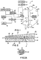
- FIG. 1 an apparatus 10 is illustrated for forming a pad of non-woven, fibrous material having moisture-absorbent material and thermoplastic fibers interspersed throughout selected portions of the pad as described below.
- the apparatus 10 comprises a forming chamber 12 having an inlet 14 and an outlet 16.
- An endless perforated conveyor 18 carried by feed rollers 20a-d is movable through the forming chamber 12 between its inlet 14 and outlet 16 in the direction indicated by the arrows in Fig. 1.
- the conveyor 18 is movable over a plenum 22 mounted on one side of the perforated conveyor 18, and this plenum 22 is connected to a vacuum source 24.
- a fiber supply conduit 26 is connected to the conveyor inlet end of forming chamber 12 at a position near the bottom of forming chamber 12 as viewed in Fig. 1.
- the fiber supply conduit 26 is connected to a source (not shown) of fibrous material 28 such as cellulose fluff, wood pulp, textile fibers or other suitable fibrous materials.
- fibrous material 28 is pulled into the forming chamber 12 and drawn onto the conveyor 18 by operation of the vacuum source 24 and plenum 22.
- the vacuum applied on one side of the conveyor 18 through the plenum 22 is effective to cause the fibrous material 28 to be drawn onto the opposite side of conveyor 18 between the inlet 14 of forming chamber 12, where the plenum 22 begins, and the outlet 16 of forming chamber 12 where the plenum 22 ends.
- non-woven pad 30 of intertwined wood pulp or fluff fibers whose thickness gradually increases from an area of minimum thickness near the inlet 14 of forming chamber 12 to an area of maximum thickness at the outlet 16 thereof.
- the non-woven pad 30 thus has a bottom surface 32 resting on one side of the conveyor 18, and a top surface 34 which slopes upwardly relative to the conveyor 18 from the inlet 14 toward the outlet 16 of forming chamber 12.
- a principal feature of this invention is the formation of a non-woven pad 30 in which highly moisture-absorbent material and thermoplastic, polymeric binder material are intermixed with selected portions of the fibrous material 28 being drawn onto the conveyor 18 such that the moisture-absorbent material and thermoplastic material are interspersed throughout selected portions of the thickness of the non-woven pad 30.
- the moisture-absorbent material employed in the method and apparatus of this invention is preferably a substantially water-insoluble absorbent polymer having a high capacity for absorbing water and body fluids, as disclosed, for example, in U.S. Patent Nos. 3,997,484; 3,661,815; 4,117,222; and, 3,936,441, the disclosures of which are incorporated by reference in their entireties herein.
- the moisture-absorbent material is depicted in the form of granules or particles 36, but it is contemplated that such moisture-absorbent material could take other forms such as strands or the like.
- the polymeric binder material discussed herein is intended to refer to thermoplastic materials such as hot melt adhesive material, preferably in the form of thermoplastic fibers 38, i.e., thin, strand-like strings or fibers of hot melt adhesive made with a die head of the type described below. It is contemplated, however, that such polymeric binder material could be introduced into the chamber 12 other than in fiber form, as desired.
- a method and apparatus for introducing moisture-absorbent particles 36 into a predetermined portion of the non-woven pad 30, while maintaining other portions of the non-woven pad 30 free of such particles 36 is disclosed in US-A-4,927,346 entitled “Apparatus For Depositing Moisture-Absorbent Material In A Substrate", which is commonly assigned to the assignee of this invention, and the disclosure of which is incorporated by reference in its entirety herein.
- the moisture-absorbent particles 36 are introduced into the non-woven pad 30 by a spray gun 40 of the type disclosed in U.S. Patent No.
- Particles 36 are supplied to spray gun 40 from a supply hopper 42 connected to an electrical controller 44, such as a programmable controller, which is also connected to an air supply 46.
- the spray gun 40 is operative to discharge the moisture-absorbent particles 36 into the interior of forming chamber 12 at a predetermined location 48 along the angled, top surface 34 of the non-woven pad 30 being formed on the conveyor 18.
- the moisture-absorbent particles 36 intermix with the fibrous material 28 being drawn onto the conveyor 18 at the predetermined location 48 to form a center layer 50 of intermixed fibrous material 28 and moisture-absorbent particles 36 within a predetermined portion of the thickness of non-woven pad 30 while maintaining the other portions of the non-woven pad 30 substantially free of moisture-absorbent particles 36. See Fig. 2.
- the separate, center layer 50 within the thickness of non-woven pad 30 is obtained, in part, by the discharge of moisture-absorbent particles 36 at the predetermined location 48.
- the fibrous material 28 introduced into the forming chamber 12 is drawn onto the conveyor 18 and begins to build up as the conveyor 18 moves through the forming chamber 12.
- a bottom section or layer 52 of the non-woven pad 30 has already been formed.
- the moisture-absorbent particles 36 discharged from the spray gun 40 intermix with the fibrous material 28 in the vicinity of the predetermined location 48, and this mixture is drawn toward the conveyor 18 atop the bottom layer 52 of the non-woven pad 30 which has already been formed.
- the center layer 50 of intermixed moisture-absorbent particles 36 and fibrous material 28 is formed atop the bottom layer 52.
- the conveyor 18 then continues to move toward the outlet 16 of forming chamber 12, downstream from the predetermined location 48 and spray gun 40, where additional fibrous material 28 is drawn toward the conveyor and atop the center layer 50 to form a top section or layer 54 of the non-woven pad 30.
- a non-woven pad 30 is thus formed having a bottom layer 52 of fibrous material 28, and intermediate or center layer 50 of intermixed moisture-absorbent particles 36 and fibrous material 28, and a top layer 54 of fibrous material 28 wherein the bottom and top layers 52, 54 are substantially free of moisture-absorbent particles 36.
- thermoplastic fibers 38 into the center layer 50 so that such center layer 50 is formed of an intermixture of fibrous material 28, moisture-absorbent particles 36 and thermoplastic fibers 38 as schematically illustrated in Figs. 2 and 2A.
- the purpose of adding the thermoplastic fibers 38 to this layer 50 is to help retain the moisture-absorbent particles 36 within such layer 50 and prevent their escape either completely out of the non-woven pad 30 or into the bottom and top sections 52, 54. This allows less fibrous material to be utilized in forming the non-woven pad 30 without reducing its moisture-absorbent capacity.
- the thermoplastic fibers 38 increase the stability and structural integrity of the center layer 50, as well as the tear strength thereof, particularly when the non-woven pad 30 becomes wet during use.
- thermoplastic material die head 56 is disposed at least partially within the interior of forming chamber and its discharge outlet 58 is oriented at approximately a 45° angle relative to the conveyor 18.
- the die head 56 is supplied with a polymeric binder material such as hot melt adhesive material from an adhesive spray gun 60 of the type disclosed in U.S. Patent No. 4,785,996, owned by the same assignee as this invention, the disclosure of which is incorporated by reference in its entirety herein.
- the spray gun 60 is effective to supply adhesive continuously or intermittently to the die head 56 in response to signals from an adhesive supply and controller 62 of the type sold by Nordson Corporation of Amherst, Ohio, the assignee of this invention, under the name "Series 3700 Applicator".
- This adhesive supply and controller 62 is effective to supply molten hot melt adhesive to the spray gun 60, and to control the operation of the spray gun 60, so that adhesive is supplied to the die head 56 as required.
- the die head 56 is also supplied with heated air from an air heater 64 connected to an air supply 66.
- the air heater 64 is a commercially available unit, and one preferred type of air heater 64 is sold under the trade name "Chromolox" by Anderson Bohls Company of Cleveland, Ohio.
- thermoplastic material die head 56 is effective to introduce thermoplastic fibers 38 into the interior of forming chamber 12 for intermixture with the fibrous material 28 and moisture-absorbent particles 36 being drawn onto the conveyor 18 at the predetermined location 48.
- the thermoplastic material die head 56 is located above the spray gun 40, and is angled at about 45° relative to conveyor 18, such that the thermoplastic fibers 38 are directed toward the conveyor 18 and across the path of the moisture-absorbent particles 36 discharged from spray gun 40. This produces an intermediate or center layer 50 within the non-woven pad 30 consisting of an intermixture of fibrous material 28, moisture-absorbent particles 36 and thermoplastic fibers 38.
- Fig. 1 the thermoplastic material die head 56 is effective to introduce thermoplastic fibers 38 into the interior of forming chamber 12 for intermixture with the fibrous material 28 and moisture-absorbent particles 36 being drawn onto the conveyor 18 at the predetermined location 48.
- the thermoplastic material die head 56 is located above the spray gun 40, and is angled at about 45° relative to conveyor 18, such that
- thermoplastic fibers 38 preferably intertwine with the fibrous material 28 and particles 36, and bond thereto, which binds or retains the particles 36 to the fibrous material 28 and substantially prevents the migration of such particles 36 from the center layer 50.
- the remaining areas of the thickness of non-woven pad 30, i.e., bottom layer 52 and top layer 54, are maintained substantially free of both moisture-absorbent particles 36 and thermoplastic fibers 38.
- the forming chamber 12 is a "Nuova Red" vertical forming chamber, sold by Nuova Red Italiana S.P.A. of Gropello Cairoli, Italy, having a height or vertical dimension as viewed in Fig. 1 of about 50 inches and a width of about 15.5 inches.
- the Nuova Red vertical forming chamber is operated to manufacture a non-woven pad 30, specifically for disposable diapers, at a rate of about 250 diapers per minute.
- a venturi powder pump mounted to a feed hopper is connected to a conduit located about 24 inches from the base or inlet 14 of forming chamber 12 in essentially the same position as spray gun 40 illustrated in Fig. 1.
- the thermoplastic material die head 56 is positioned above the spray gun 40 and angled at approximately 45° relative to the conveyor 18 so that the thermoplastic fibers 38 discharged therefrom are directed toward a location about 15 inches in height from the bottom or inlet 14 of forming chamber 12.
- the system operating parameters are as follows: Fibrous Material Flow Rate 36 grams per diaper Hot Melt Adhesive HL-6149X (polyamide) H.B.
- a non-woven pad 30 is obtained having a bottom layer 52 of fibrous material 28, a center layer 50 of intermixed fibrous material 28, moisture-absorbent particles 36 and thermoplastic fibers 38, and a top layer 54 of fibrous material 28 wherein the bottom and top layers 52, 54 are substantially free of both moisture-absorbent particles 36 and thermoplastic fibers 38.
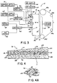
- thermoplastic material die head 68 located at least partially within the interior of forming chamber 12 in a position to introduce thermoplastic fibers toward the predetermined location 48.
- a second adhesive supply and controller 70 and a second adhesive spray gun 72 are associated with the second thermoplastic material die head 68, and this equipment is identical to the adhesive supply and controller 62 and spray gun 60 connected to thermoplastic material die head 56 illustrated in Fig. 3 and described above in connection with Figs. 1 and 2.
- the second die head 68 is located at least partially within the forming chamber 12 in position to introduce the thermoplastic fibers 74 at the predetermined location 48 relative to the conveyor 18 where the moisture-absorbent particles 36 are discharged from spray gun 40.
- a non-woven pad 76 is thus formed in the identical manner as described above in connection with the non-woven pad 30, having an angled top surface 77 and a bottom surface 79 resting on conveyor 18, except the non-woven pad 76 has an intermediate or center layer 78 formed of an intermixture of four materials, i.e., fibrous material 28, moisture-absorbent particles 36, thermoplastic fibers 38 and thermoplastic fibers 74.
- the top and bottom layers 80, 82, respectively, of non-woven pad 76 are maintained substantially free of moisture-absorbent particles 36 and thermoplastic fibers 38, 74 in the same manner described above in the embodiment of Figs. 1 and 2.
- thermoplastic fibers 38 and 74 introduced into the center or intermediate layer 78 of non-woven pad 76 are intended to produce specific properties in the center layer 78.
- the thermoplastic fibers 38 are formed from a polymeric binder material such as a polyamide thermoplastic hot melt adhesive, or other suitable materials having relatively high tensile strength.
- Such thermoplastic fibers 38 impart additional strength, stability and tear resistance to the intermediate layer 78, particularly when the non-woven pad 76 becomes wet.
- the thermoplastic fibers 74 are preferably formed from a material such as polyethylene, polypropylene or other suitable types of thermoplastic binder materials which aid in retaining the "loft" of the intermediate layer 78.
- thermoplastic fibers 74 formed of polyethylene material help maintain air gaps between the fibrous material 28 in the center layer 78 so that it retains a "fluff-like" consistency which is resistant to compression as, for example, when a baby sits on a disposable diaper made with a non-woven pad 76.
- the embodiment of Figs. 3 and 4 is essentially identical to that discussed above in connection with Figs. 1 and 2.
- thermoplastic material die head 83 is located at least partially within the forming chamber 12 in a position upstream from or below the particle spray gun 40 and the predetermined location 48 as viewed in Figs. 5 and 6, and an upper die head 84 is positioned at least partially within forming chamber 12 at a location above or downstream from the particle spray gun 40 and the predetermined location 48.
- Both of these die heads 83, 84 are identical to die heads 56 and 68, and are supplied with thermoplastic material in the same manner and with the same equipment depicted in Figs. 1-4A.
- die head 83 is supplied with thermoplastic material from an adhesive supply and controller 85 and spray gun 86, whereas die head 84 is supplied by adhesive supply and controller 87 and spray gun 88.
- fibrous material 28 is drawn onto the conveyor 18 in the embodiment of Figs. 5 and 6 in the identical manner as described above to produce a non-woven pad 89 having an angled top surface 90 and a bottom surface 91 resting on conveyor 18.
- thermoplastic fibers and moisture-absorbent material are introduced at different locations within the thickness of the non-woven pad 89.
- thermoplastic fibers 38 intermix with fibrous material 28 being drawn onto the conveyor 18 at a location upstream from the predetermined location 48, thus forming a bottom layer 92 of intermixed fibrous material 28 and thermoplastic fibers 38.
- moisture-absorbent particles 36 are discharged from particle spray gun 40 at the predetermined location 48 and these moisture-absorbent particles 36 intermix with the fibrous material 28 thereat to form a center layer 93 of intermixed fibrous material 28 and moisture-absorbent particles 36 atop the bottom layer 92.
- the upper thermoplastic material die head 84 discharges thermoplastic fibers 38 into an area between the predetermined location 48 where particle spray gun 40 is positioned and the outlet 16 of forming chamber 12.
- thermoplastic fibers 38 from upper thermoplastic material die head 84 intermix with fibrous material 28 being drawn onto conveyor 18 downstream from predetermined location 48 to form a top layer 94 of intermixed fibrous material 28 and thermoplastic fibers 38 atop the intermediate layer 93.
- the non-woven pad 89 thus comprises a bottom layer 92 of intermixed fibrous material 28 and thermoplastic fibers 38, and intermediate layer 93 of intermixed fibrous material 28 and moisture-absorbent particles 36 and a top layer 94 of intermixed fibrous material 28 and thermoplastic fibers 38.
- the bottom layer 92 and top layer 94 are intended to prevent or reduce the loss or migration of moisture-absorbent particles 36 from the interior of the non-woven pad 89.
- the thermoplastic fibers 38 within bottom layer 92 and top layer 94 are effective to resist the passage of moisture-absorbent particles 36 therethrough, but permit the passage of fluids into the intermediate layer 93 for absorption by the moisture-absorbent particles 36.
- FIGs. 10A-10D further alternative embodiments of the method and apparatus of this invention are illustrated.
- Figs. 10A and 10B each disclose an apparatus identical in structure and operation to that shown in Fig. 1, as described above, except for the addition of structure for positioning a moisture-wicking substance such as a surfactant at the exterior surface of the thermoplastic fibers 38 introduced into the forming chamber 12.
- Figs. 10C and 10D disclose apparatus identical in structure and operation to that illustrated in Fig. 5, as described above, except for the addition of structure to position a moisture-wicking substance at the exterior surface of the thermoplastic fibers 38 introduced into forming chamber 12.
- thermoplastic fibers 38 It may be desirable in some applications to increase the wicking or moisture transfer capability of the thermoplastic fibers 38 so that moisture is more efficiently transferred to the moisture-absorbent particles 36 within the non-woven pad.
- the embodiments of Figs. 10A and 10B form a non-woven pad 30, and the embodiments of Figs. 10C and 10D form a non-woven pad 89, in the identical manner described above in connection with Figs. 1 and 5, respectively.
- These pads 30, 89 each comprise bottom, center and top layers in which the moisture-absorbent material 36 is directed into the center layer and the thermoplastic fibers 38 are either directed into the center layer or into both the top and bottom layers, as described above.
- a moisture-wicking substance such as a surfactant applied at the exterior surface of the thermoplastic fibers 38 may increase the wicking capability of such fibers 38 so that moisture entering the top, bottom or center layers of the non-woven pads 30, 89 is wicked or transferred by the fibers 38 to the moisture-absorbent particles 36 within the center layer thereof. This enhances the moisture-absorbent capacity of the non-woven pads 30, 89.
- moisture-wicking substance is meant to refer to compositions such as surfactants or plasticizers, which, when present in an effective amount on the exterior surface of the thermoplastic fibers 38, are intended to increase the wicking or moisture transmitting capability of the thermoplastic fibers 38.
- surfactant believed to be suitable is Tritan-X 100 manufactured by Rohm & Haas Company of Philadelphia, Pennsylvania.
- examples of other moisture-wicking substances believed to be suitable include arylalkyd sulfates, polyethylene glycol, fatty acid esters, polyethers, phosphate esters, alkyd diethanolamines and glyceryl monostearates.
- surfactants for purposes of the present description, such moisture-wicking substances are referred to herein as "surfactants", it being understood that such term is used by way of example and is not intended to be restrictive of the types of moisture-wicking substances suitable for use.
- a surfactant supply 210 is connected to the adhesive supply and controller 62 through a manually operated valve 212.
- Surfactant is allowed to intermix with the hot melt adhesive within the adhesive supply and controller 62, with the valve 212 in an open position, and this mixture or blend is transmitted to the die head 56.
- the die head 56 produces thermoplastic fibers 38 in which at least some of the surfactant is located on the exterior surface thereof, and these fibers 38 are discharged into the forming chamber 12.
- the surfactant supply 210 is a pressure pot of the type sold commercially by Nordson Corporation of Amherst, Ohio under Nordson Part No. 270,963.
- the surfactant could be supplied from a 55 gallon drum, for example, through a piston pump such as a Model 25B pump, manufactured by Nordson Corporation of Amherst, Ohio.
- the manual valve 212 can be essentially any suitable type of commercially available valve, or, alternatively, an automatically operated valve such as a solenoid valve controlled by the adhesive supply and controller 62.
- surfactant is introduced by a spray gun 214 directly into the forming chamber 12 in the path of the thermoplastic fibers 38 discharged from die head 56 so that the exterior surface of at least some of the thermoplastic fibers 38 is coated with the surfactant to increase their moisture-wicking capability.
- the spray gun 214 is supplied with surfactant by a surfactant supply 216 connected to a pump 218.
- the spray gun 214 is a Model A7A airless spray gun sold by Nordson Corporation of Amherst, Ohio.
- the surfactant supply 216 and pump 218 can be any commercially available components suitable for use with surfactants, such as a drum and the Nordson Model 25B pump mentioned above.
- Figs. 10C and 10D each disclose structure for positioning a surfactant at the exterior surface of the thermoplastic fibers 38 in the top and bottom layers 94, 92 of non-woven pad 89.
- a surfactant supply 220 is connected by a line, carrying a valve 222 to a mixer block 224.
- the mixer block 224 is formed with a throughbore 226 connected to a transverse bore 228. One end of the throughbore 226 is connected to the air heater 64 and the transverse bore 228 is connected to the line from surfactant supply 210.
- the heated air and surfactant are intermixed within the mixer block 224 and discharged through the opposite end of throughbore 226 into a line which connects to each die head 83 and 84.
- the intermixed surfactant and heated air is then combined with the thermoplastic material within each die head 83, 84 to form a blend.
- Each of the die heads 83, 84 is effective to discharge thermoplastic fibers 38 into the non-woven pad 89, as described in connection with Fig. 5, wherein at least a portion of the surfactant is located or positioned at the exterior surface of the fibers 38 in an effective amount so that the moisture-wicking capability of the fibers 38 is increased.
- FIG. 10D A still further embodiment illustrating structure for introducing surfactant into the forming chamber 12 is illustrated in Fig. 10D.
- a pump 230 is mounted to a surfactant supply 232 and is connected to a first spray gun 234 located near die head 84 and a second spray gun 236 located near die head 83.
- Each of these spray guns 234, 236 are preferably airless spray guns such as spray gun 214.
- the spray guns 234, 236 are effective to introduce surfactant into the interior of forming chamber 12 in the path of the thermoplastic fibers 38 discharged from die heads 84 and 83, respectively, so that the exterior surface of at least some of the fibers 238 become at least partially coated with surfactant to increase the moisture-wicking capability thereof.
- a non-woven pad 200 which includes a series of longitudinally spaced areas 202 of intermixed fibrous material 28, moisture-absorbent particles 36 and thermoplastic fibers 204 located within a portion of the thickness of the non-woven pad 200.
- This non-woven pad 200 can be formed with the equipment and method depicted in any of the embodiments illustrated in Figs. 1-6 and 10A-10D, as desired.
- the longitudinally spaced areas 202 are formed of intermixed fibrous material 28, moisture-absorbent particles 36 and thermoplastic fibers 38 located approximately in the center of non-woven pad 202.
- the longitudinally spaced areas 202 are formed of intermixed fibrous material 28, moisture-absorbent particles 36 and thermoplastic fibers 38 located approximately in the center of non-woven pad 202.
- the longitudinally spaced areas 202 are also located at the center of non-woven pad 200 but two types of thermoplastic fibers 38, 74 are intermixed with the fibrous material 28 and moisture-absorbent particles 36 thereat.
- the non-woven pad 200 made in accordance with the method and apparatus of Fig. 5 has longitudinally spaced areas 202 within the three layers of the pad, in vertical alignment with one another, wherein one area 202 at the bottom of the pad 200 includes intermixed fibrous material 28 and thermoplastic fibers 38, another area 202 at the center of pad 200 includes intermixed fibrous material 28 and moisture-absorbent particles 36 and a third area 202 at the top of the pad 200 includes intermixed fibrous material 28 and thermoplastic fibers 38.
- the longitudinally spaced areas 202 in pad 200 formed in accordance with the method of each of the embodiments of Figs. 1-6 are obtained by operating the spray gun 40 and the die heads 56, 68, 83 and/or 84 intermittently so that moisture-absorbent particles 36 and thermoplastic fibers 38 or 74 are introduced only in the longitudinally spaced areas 202 of pad 200.
- the controller 44 is operative to control the intermittent operation of spray gun 40, and the identical adhesive supply and controllers 62, 70, 85 and/or 87 are operative to control the supply of thermoplastic material to the die heads 56, 68, 83 and 84, respectively.
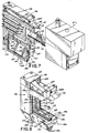
- thermoplastic material die head 56, 68, 83 and 84 the detailed structure of thermoplastic material die head 56, 68, 83 and 84, all of which are identical, is illustrated.
- Each of these thermoplastic material die heads comprises a die head body 96 formed with an adhesive inlet 98 which is connected by a vertical passage 100 to a transfer passage 102.
- This transfer passage 102 is connected to four ports 104 formed at the base 106 of die head body 96.
- the side wall 108 of die head body 96 mounts an adaptor plate 110 having a passage 112 which communicates with the adhesive inlet 98 in die head body 96.
- This adaptor plate 110 has a coupling 114 which mounts to the nozzle 116 of an adhesive dispenser gun such as dispenser 60 illustrated in Fig. 1.
- the adhesive dispenser 60 is effective to introduce the thermoplastic hot melt adhesive, continuously or intermittently as controlled by adhesive supply and controller 62, into the die head body 96 through the adaptor plate 110 and the adhesive inlet 98 in die head body 96.
- the hot melt adhesive is maintained in a molten state by three heaters 115a-c, each carried within bores formed in the center portion of die head body 96 above transfer passage 102.
- An RTD 117 is also mounted in the die head body 96 near the heaters 115a-c to monitor the temperature thereat.
- the top wall of die head body 96 as viewed in Fig. 7 mounts a rectangular-shaped air cap 118 having a hollow interior forming an air chamber 120. Heated air is supplied into the air chamber 120 through ports 122a,b on either side thereof, each of which are connected to the air heater 64 mentioned above. See Fig. 1. As best shown in Fig. 8, the heated air introduced into the air chamber 120 of air cap 118 is distributed into air passages 124, 126 formed in opposite sides of the die head body 96. Preferably, there are four air passages 124 on one side of die head body 96, and another four air passages 126 on the opposite side thereof.
- the base 106 of die head body 96 mounts a nozzle block 126.
- the nozzle block 126 is formed with a center, hot melt discharge plenum 128 and two air plenums 130, 132 located on either side of the hot melt discharge plenum 128.
- the hot melt discharge plenum 128 has an oval-shaped projection 134 which rests against the base 106 of die head body 96 so that the adhesive ports 104 in the die head body 96 communicate with the interior of hot melt discharge plenum 128 in the nozzle block 126.
- This projection 134 forms a shoulder 136 which mounts downwardly projecting flanges 138, 139 formed on each end of the base 106 of die head body 96.
- an O-ring 140 is interposed between the flanges 138, 139 and projection 134 to form a fluid-tight seal therebetween.
- the nozzle block 126 and die head body 96 are preferably interconnected by screws 141.
- the bottom portion of the hot melt discharge plenum 128 in nozzle block 126 is formed with a plurality of discharge outlets 142 located side-by-side along the length of the hot melt discharge plenum 128.
- Each of these discharge outlets 142 is effective to eject a separate strand 144 of thermoplastic hot melt adhesive, as depicted by the arrows in Fig. 7.
- the hot melt adhesive is transmitted to the discharge outlets 142 by the above described adhesive flow path, i.e., adhesive is first introduced from the adhesive spray gun 60 into the passage 112 of adaptor plate 110 where it flows into the adhesive inlet 98 of die head body 96.
- the adhesive is directed through the vertical passage 100 of die head body 96 to the transfer passage 102.
- Each of the ports 104 at the base 106 of die head body 96 connected to transfer passage 102 transmit the adhesive into the hot melt discharge plenum 128 of nozzle block 126 from which it is ejected through the discharge outlets 142.
- the adhesive strands 144 are impacted with a jet or fan of heated air after they are ejected from discharge outlets 142.
- opposite sides of the nozzle block 126 are formed with recesses 146, 147, respectively, each having an inner wall 149 and an angled outer wall 150.
- a cover plate 152 is mounted to the angled outer wall 150 over recess 146 and a cover plate 154 is mounted over the angled outer wall 150 over recess 147 to form the air plenums 130, 132, respectively.
- Each of the plates 152, 154 is formed with a longitudinally extending slot 155 in their bottom interior surfaces which form elongated discharge openings 156 at the base of each air plenum 130 and 132.
- the size of these discharge openings 156 can be varied, as desired, by employing plates 152 or 154 having longitudinal slots 155 of different size.
- Heated air entering the air chamber 120 of air cap 118 in die head body 96 is thus transmitted through the air passages 124, 126 on either side of die head body 96 into the air plenums 130 and 132. Because the cover plates 152, 154 are mounted at an angle relative to the inner walls 149 of air plenums 130, 132, the heated air discharged through the discharge opening 156 in each air plenum 130, 132 is directed at an angle relative to the path of the adhesive strands 144 ejected from discharge outlets 142 of hot melt discharge plenum 128.
- thermoplastic fibers 38 are directed by the force of the heated air emitted from air plenums 130, 132 into the interior of forming chamber 12 for combination with the fibrous material 28 and/or moisture-absorbent particles 36 as described in detail above.
- thermoplastic, polymeric binder materials are mentioned above for combination at various locations within the thickness of the non-woven pad formed in accordance with the method of this invention. It is contemplated, however, that other types of thermoplastic binder materials could be employed to achieve the same or different characteristics of the non-woven pad as desired.
- thermoplastic materials mentioned herein are thus not intended to be restrictive, it being understood that other types of materials could be injected at various, discreet locations along the non-woven pad formed within the forming chamber 12, as desired.
- Figs. 10A-10D for introducing surfactant as a coating for the thermoplastic fibers are essentially interchangeable with one another and can be used with the embodiment of Fig. 3.
- the surfactant supply 210 and valve 212 shown in Fig. 10A can also be employed to introduce surfactant into the adhesive supply and controllers 62, 70 of Fig. 3 and/or the adhesive supply and controllers 85, 87 of Fig. 5.
- the mixer head 224 and associated structure illustrated in Fig. 10C can be employed to supply surfactant to the die head 56 of Fig. 1 and/or the die heads 56, 68 of Fig. 3.
Landscapes
- Health & Medical Sciences (AREA)
- Engineering & Computer Science (AREA)
- Animal Behavior & Ethology (AREA)
- General Health & Medical Sciences (AREA)
- Biomedical Technology (AREA)
- Heart & Thoracic Surgery (AREA)
- Vascular Medicine (AREA)
- Life Sciences & Earth Sciences (AREA)
- Veterinary Medicine (AREA)
- Epidemiology (AREA)
- Public Health (AREA)
- Textile Engineering (AREA)
- Manufacturing & Machinery (AREA)
- Absorbent Articles And Supports Therefor (AREA)
- Processing And Handling Of Plastics And Other Materials For Molding In General (AREA)
- Nonwoven Fabrics (AREA)
Abstract
Description
- This invention relates to a method and apparatus for making moisture-absorbent substrates, and, more particularly, to a method and apparatus for interspersing highly moisture-absorbent particles and thermoplastic hot melt adhesive material throughout predetermined portions of a fibrous material pad in a non-woven product.
- Hygienic articles such as disposable diapers, sanitary napkins, incontinence pads and sick bed sheets must have a high moisture absorption capacity to effectively retain eliminated body fluids for acceptable periods of time. Early hygienic articles of this type employed cellulose wadding, fluff cellulose or absorbent cotton as the absorbent materials. One problem with these materials is that their moisture-retaining capacity is relatively small compared to their volume. In order to improve the moisture-retaining capacity of hygienic articles made from these materials, the volume of such absorbent materials in the hygienic article must be increased. This produces a bulky product which is unacceptable in many hygienic articles, particularly sanitary napkins.
- In an effort to reduce the volume and size of hygienic articles, and increase their absorbent capacity, one layer of such articles comprises a non-woven pad formed of cellulose fluff, wood pulp, textile fibers or other non-woven fibrous materials in which highly moisture-absorbent material is combined within the fiber structure of the pad. These highly moisture-absorbent materials are preferably water-insoluble absorbent polymers having a high capacity for absorbing water and body fluids, which are partially or wholly synthetic and are commercially available in fine-grain, particulate form. See, for example, U.S. Patent Nos. 3,997,484; 3,661,815; 4,117,222; and, 3,936,441.
- One system for forming the non-woven fibrous materials into a non-woven pad is disclosed in U.S. Patent No. 3,984,272. In this system, a forming chamber having an inlet and outlet is connected by a feed conduit to a source of fibrous materials such as finely ground wood pulp. A perforated conveyor is movable through the forming chamber between its inlet and outlet, and structure is provided to draw a vacuum on one side of the perforated conveyor. The fibrous material introduced into the chamber is drawn onto the opposite side of the conveyor by the vacuum, and this fibrous material forms a non-woven pad on the conveyor which increases in thickness in a direction from the inlet of the chamber toward its outlet. The non-woven pad thus has a bottom surface resting atop the conveyor and a top surface which angles or slopes upwardly relative to the conveyor from the inlet of the chamber toward its outlet. A leveling or scarfing roller near the outlet of the forming chamber is operative to remove at least a portion of the fibrous material at the top of the non-woven pad to produce a non-woven pad of uniform thickness. The pad is then transmitted by the conveyor through the outlet of the forming chamber for subsequent operations to form the completed hygienic article.
- Two methods have been employed to incorporate highly moisture-absorbent material into the non-woven pad formed within the forming chamber in systems of the type disclosed in Patent No. 3,984,272 and described above. In one method, the highly moisture-absorbent material is injected into the same feed conduit which supplies the fibrous material into the interior of the chamber. The highly moisture-absorbent material and fibrous material are intermixed within the feed conduit to completely intersperse the moisture-absorbent material throughout the fibers prior to introduction into the forming chamber. This produces a non-woven pad atop the conveyor within the chamber in which the moisture-absorbent material is present throughout the entire thickness, width and length of the non-woven pad.
- One problem with the above-described method is the loss of moisture-absorbent material through the perforated conveyor in the forming chamber. As the fibers and moisture-absorbent material mixture is drawn onto the perforated conveyor to form the non-woven pad, moisture-absorbent material at the lower portion of the non-woven pad is drawn through the conveyor into a filter-reclamation system. Some of the moisture-absorbent material is lost. Additionally, the moisture-absorbent material is difficult to contain even with the filtering system, and environmental contamination can result.
- Another problem with this method is that the moisture-absorbent material is distributed throughout the non-woven pad across its entire length, width and thickness. This produces substantial waste because in subsequent forming operations, the non-woven pad is cut to the desired length of the hygienic article. In addition, the application of moisture-absorbent material across the entire width of the non-woven pad may be unnecessary for some types of hygienic articles, particularly disposable diapers where the leg holes are cut at the edges of the layer.
- Another method of combining moisture-absorbent material with the non-woven pads employed in hygienic articles involves the application of moisture-absorbent material onto the top surface of the non-woven pad downstream from the leveling or scarfing rollers and outside of the forming chamber. Accordingly, a non-woven pad is produced having moisture-absorbent material concentrated on its top surface with substantially no moisture-absorbent material within the remaining thickness of the pad.
- One disadvantage of this second method relates to the handling and loss of the moisture-absorbent material applied to the pad. Because the application of moisture-absorbent material takes place outside of the forming chamber in this method, a relatively expensive collection system is required to capture the oversprayed moisture-absorbent material and prevent it from escaping to the environment. Migration of the moisture-absorbent material out of the pad is a particular problem in this method because all of the powder is concentrated at its top surface. In particulate or granular form, the moisture-absorbent material can be readily dislodged from the type of pads which are not sealed at the ends.
- Another problem with this second method of incorporating the highly moisture-absorbent material into the non-woven pad is that the material is concentrated on top of the pad. This causes so-called "gel blockage" wherein the moisture-absorbent material at the top of the non-woven pad become saturated with fluid and prevents the wicking or transfer of moisture to the fibrous material in the remaining portion of the pad. As a result, the fluid is retained at the surface of the pad in contact with the wearer of the hygienic article causing discomfort. Additionally, only a relatively small portion of the entire thickness of the pad is effectively employed to absorb the moisture.
- These problems have been addressed in US-A-4,927,346 entitled "Apparatus For Depositing Moisture-Absorbent Material In A Substrate", which is commonly owned by the assignee of the instant application. The apparatus disclosed in US-A-4,927,346 employs essentially the same type of forming chamber disclosed in Patent No. 3,984,272, but is effective to intermix highly moisture-absorbent material with fibrous material in a predetermined portion of the thickness of the pad and, if desired, at longitudinally spaced locations therealong. A dispenser, such as a spray gun, is located at least partially within the forming chamber at a predetermined location with respect to the upwardly sloping top surface of the non-woven pad of fibrous material being drawn onto the conveyor. The dispenser is effective to intermix highly moisture-absorbent material with a portion of the fibrous material being drawn onto the conveyor at such predetermined location. This forms a layer of intermixed fibrous material and particulate material within a predetermined portion of the thickness of the pad while maintaining another portion of the thickness of the non-woven pad substantially free of particulate material.
- Expressed in other terms, the apparatus disclosed in US-A-4,927,346 forms a non-woven pad in which fibrous material is drawn onto the conveyor beginning at the inlet to the forming chamber, and such fibrous material begins to build up on the conveyor between the inlet and the location of the spray gun for the highly moisture-absorbent material. This forms a bottom layer of the non-woven pad resting directly on the conveyor which increases in thickness in the direction of movement of the conveyor through the chamber. The spray gun intermixes a second material, e.g., highly moisture-absorbent particulate material, with the fibrous material being drawn onto the conveyor at the predetermined location where the spray gun is positioned at least partially within the forming chamber. This intermixture of fibrous material and particulate material forms an intermediate layer which is drawn onto the bottom layer of fibrous material already accumulated on the conveyor upstream from the location of the spray gun. As the conveyor continues moving toward the outlet of the forming chamber, additional fibrous material is drawn toward the conveyor forming a top layer of fibrous material over the intermediate layer of intermixed fibrous material and moisture-absorbent material. As a result, a non-woven pad is formed having a bottom layer of fibrous material, an intermediate layer of intermixed fibrous material and particulate material and a top layer of fibrous material wherein the top and bottom layers of fibrous material are substantially free of moisture-absorbent material.
- The apparatus described above which is the subject of US-A-4,927,346 substantially improves upon the methods described above in a number of respects. The problem of gel blockage is substantially eliminated because the highly absorbent material is concentrated preferably at the core or center portion of the non-woven pad as opposed to near its upper surface. The loss of the particulate moisture-absorbent material is reduced and problems of over-spray of such material are substantially eliminated. Additionally, by locating the moisture-absorbent material at selected areas within the thickness and length of the pad, a substantial savings in the amount of moisture-absorbent material required is achieved.
- Despite the improvements obtained by the apparatus disclosed in US-A-4,927,346 certain limitations have been observed in the manufacture of non-woven pads for some types of hygienic articles. For example, even though the highly moisture-absorbent, particulate material is concentrated within the center layer of the non-woven core using such method and apparatus, migration of the particulate material through the surrounding fibrous material layers can still occur. Given the further steps required in the process for forming the completed hygienic article, and the packaging and shipment of such hygienic articles, migration of the highly absorbent particulate material into the surrounding fibrous material or entirely through the non-woven pad is a possibility.
- Additionally, it is desirable to increase the structural integrity of the non-woven pad, and particularly that portion of the thickness of the pad containing the highly moisture-absorbent material. It has been found that when the non-woven pad becomes wet, with such wetness being concentrated in the area of the highly moisture-absorbent material, the integrity and stability of the center of the pad is reduced and can present problems of tearing.
- US-A1-4,724,114 discloses a way of manufacturing non-woven mulitlayer fabrics which additionally contain a particulate superabsorbent material within at least one layer. This known way requires one melt blown apparatus per layer, of which the first apparatus deposits on a moving belt a fibrous material. A further meltblown apparatus deposits upon the moving fibrous material deposited by the first meltblown apparatus a second layer of fibrous material which may include the superabsorbent material. Thus, the different layers of the product are deposited stepwise with a relatively distinct borderline between every to adjacent layers.
- It is therefore among the objectives of this invention to provide a method and apparatus for the formation of a pad of non-woven fibrous material containing a second material such as moisture-absorbent material interspersed throughout a predetermined portion of the thickness of the non-woven pad, which minimizes waste of the moisture-absorbent material, which increases the structural integrity and stability of the non-woven pad and which permits the use of less fibrous material while maintaining the moisture-retaining capacity of the non-woven pad.
- The objectives are accomplished in a method and apparatus of forming a non-moving pad of fibrous material in accordance with the teaching of claims 1 or 5. According thereto, the fibrous materials are introduced through a feed conduit into a forming chamber having an inlet and an outlet. A perforated conveyor is movable between the inlet and outlet of the forming chamber and a vacuum is applied on one side of the conveyor to draw the fibrous material onto the opposite side of the conveyor. In the course of being drawn onto the perforated conveyor, the fibrous material forms a non-woven pad having a bottom surface resting atop the conveyor and a top surface which slopes upwardly relative to the conveyor from the inlet of the chamber toward its outlet. At a predetermined location relative to the sloped, top surface of the non-woven pad, a dispenser located at least partially within the chamber is effective to intermix highly moisture-absorbent material with the fibrous material being drawn onto the conveyor at such predetermined location. Simultaneously, a second dispenser, also disposed at least partially within the interior of the chamber, is effective to intermix a thermoplastic hot melt adhesive in strand or fiber form, or other polymeric binder material, with the fibrous material and moisture-absorbent material being drawn onto the conveyor at such predetermined location. As a result, a layer of intermixed fibrous material, moisture-absorbent material and thermoplastic fibers is formed within a predetermined portion of the thickness of the non-woven pad while maintaining another portion of the thickness of the non-woven pad substantially free of the moisture-absorbent material and thermoplastic fibers.
- This invention is therefore predicated upon the concept, in one presently preferred embodiment, of forming a non-woven pad having a discreet layer of intermixed fibrous material, moisture-absorbent material and thermoplastic fibers within a predetermined portion of the thickness of the pad while the remainder of the pad is maintained substantially free of the moisture-absorbent material and thermoplastic fibers. One purpose of the thermoplastic fibers in this embodiment is to become entangled with the fibrous material and moisture-absorbent material to help retain the moisture-absorbent material in position within such layer of the non-woven pad. Preferably, the moisture-absorbent material is located at the center portion or layer of the pad, and the thermoplastic fibers are effective to substantially retain the moisture-absorbent material in such location and prevent its migration to the adjacent top and bottom layers of the non-woven pad. This reduces loss of the moisture-absorbent material, and thus enhances the moisture-absorbent capacity of such non-woven pad.
- In another aspect of this embodiment, the thermoplastic fibers intermixed with the fibrous material and moisture-absorbent material at the center of the non-woven pad also function to enhance the stability and structural integrity of such layer. Particularly when the pad becomes wet, the center portion of the pad containing the moisture-absorbent material becomes heavy and concentrated with fluid because of the presence of the moisture-absorbent material and its capacity for absorbing a substantial volume of fluid. The thermoplastic fibers intermixed within this center layer of the non-woven pad helps stabilize such layer and increase its resistance to tearing, particularly when wet. It is contemplated that certain types of polymeric binder materials, such as polyamides, are particularly useful and effective to increase the tear strength and stability of such center layer of the non-woven pad formed in accordance with the method and apparatus of this invention.
- In another aspect of this invention, the amount of fibrous material used to form the pad can be reduced in that the invention permits the use of a greater amount of moisture-absorbent material. This is because the thermoplastic fiber material supplied into the pad more effectively retains the moisture-absorbent material within the center portion of the pad where the moisture-absorbent material is typically originally applied. Thus, more moisture-absorbent material can be retained in the center portion of the pad without the problem of a significant portion of the moisture absorbent material drifting from the center of the pad to the bottom of the pad where it would be less effective in increasing the moisture-absorbent capacity of the pad.
- In another aspect of this invention, a liquid surfactant can be applied with the thermoplastic fiber material to enhance the wicking capability of the thermoplastic fibers to improve the moisture-absorbent capacity of the pad. This surfactant can be intermixed with the thermoplastic material in the thermoplastic material supply container, can be mixed in with the heated air supplied to the thermoplastic material die head, or can be sprayed into the forming chamber through a spray gun positioned adjacent to the thermoplastic material die head.
- In an alternative embodiment of this invention, two separate dispensers for thermoplastic fibers are at least partially disposed within the interior of the forming chamber to intermix two types of thermoplastic polymeric binder materials with the fibrous material and highly moisture-absorbent material being drawn onto a predetermined location relative to the conveyor and the non-woven pad formed thereon. This produces a layer within the interior of the non-woven pad comprising intermixed fibrous material, moisture-absorbent material and the two types of thermoplastic materials. One of these thermoplastic materials is preferably a polyamide, or another suitable type of thermoplastic polymeric binder material having relatively high tensile strength, so that the integrity and stability of the center, intermixed layer of the non-woven pad is enhanced. The other thermoplastic polymeric binder material intermixed within this center layer is preferably a polyethylene, or an equivalent, which helps maintain air gaps or spaces between the fibrous material in such layer. In this manner, the "loft" or thickness of the fluff or fibrous material forming such center layer is retained to enhance the softness and fluff-like feel of the overall non-woven pad.
- In another embodiment of this invention, two thermoplastic fiber material dispensers are employed to introduce thermoplastic fibers on either side of the predetermined location where the highly moisture-absorbent material is intermixed with fibrous material. One thermoplastic fiber material dispenser is positioned to intermix thermoplastic fibers with fibrous material being drawn onto the conveyor upstream from the predetermined location, and the other thermoplastic fiber material dispenser is positioned to intermix thermoplastic fibers with the fibrous material being drawn onto the conveyor downstream from such predetermined location. This produces a non-woven pad which is formed with three discreet layers within the thickness thereof including a center layer of intermixed fibrous material and moisture-absorbent material, and top and bottom layers of intermixed fibrous material and thermoplastic fibers on either side of the center layer. The purpose of these top and bottom layers of intermixed fibrous material and thermoplastic fibers is to form barriers on either side of the center layer to reduce or eliminate migration of the moisture-absorbent material outwardly from the interior of the pad.
- In the presently preferred embodiment, each of the dispensers employed to introduce thermoplastic polymeric binder material into the interior of the forming chamber are extrusion die heads which are effective to form relatively thin strands or fibers of polymeric binder material, such as hot melt adhesive, and direct such thermoplastic fibers into the forming chamber. The thermoplastic fiber producing die head herein comprises a die head body formed with an inlet which transmits hot melt adhesive material to a number of adhesive passageways. The die head body also includes an air cap connected to a source of heated air which transmits heated air into a number of air passageways formed in the die head body. A nozzle block is attached to the die head body which is formed with a central, adhesive discharge plenum having a plurality of discharge outlets, and a pair of air discharge plenums formed on either side of the adhesive discharge plenum.
- Hot melt adhesive is introduced through the inlet and adhesive passageways of the die head body into the adhesive discharge plenum in the nozzle block where it is ejected from the discharge outlets therein as a number of individual adhesive strands or extrusions. At the same time, heated air is transmitted from the air cap and air passageways in the die head body into the air discharge plenums on either side of the nozzle block. The heated air is discharged from elongated outlets in the air discharge plenums, at an angle with respect to the adhesive strands, such that the heated air impacts the adhesive strands and forms elongated, thermoplastic fibers. These thermoplastic fibers are propelled by the force of the heated air into the forming chamber and toward the conveyor for intermixture with the fibrous material and/or moisture-absorbent material, as described above.
- The structure, operation and advantages of the presently preferred embodiment of this invention will become further apparent upon consideration of the following description, taken in conjunction with the accompanying drawings, wherein:
- Fig. 1 is a schematic, elevational view of one embodiment of the method and apparatus of this invention;
- Fig. 2 is an enlarged, partial view of the non-woven pad formed by the apparatus of Fig. 1;
- Fig. 2A is an enlarged, schematic view of the circled area in Fig. 2;
- Fig. 3 is a schematic, elevational view of an alternative embodiment of the apparatus of this invention;
- Fig. 4 is an enlarged, partial view of the non-woven pad formed with the apparatus of Fig. 3;
- Fig. 4A is an enlarged, schematic view of the circled area in Fig. 4;
- Fig. 5 is a schematic, elevational view of a still further embodiment of the apparatus of this invention;
- Fig. 6 is an enlarged, partial view of the non-woven pad formed in accordance with the apparatus of Fig. 5;
- Fig. 7 is an elevational view in partial cross section of the thermoplastic material die head of this invention;
- Fig. 8 is a cross sectional view of the thermoplastic material die head shown in Fig. 7, taken generally along line 8-8 thereof;
- Fig. 9 is a plan view of a non-woven pad formed with longitudinally spaced areas of intermixed fibrous material, moisture-absorbent material and thermoplastic fibers;
- Figs. 10A and 10B are schematic views, similar to Fig. 1, of alternative embodiments for introducing a surfactant onto the thermoplastic fibers discharged from the thermoplastic material die heads; and
- Figs. 10C and 10D are schematic views, similar to Fig. 5, of alternative embodiments for introducing a surfactant onto the thermoplastic fibers discharged from the thermoplastic material die heads.
- Referring now to Figs. 1 and 2, an
apparatus 10 is illustrated for forming a pad of non-woven, fibrous material having moisture-absorbent material and thermoplastic fibers interspersed throughout selected portions of the pad as described below. Theapparatus 10 comprises a formingchamber 12 having aninlet 14 and anoutlet 16. An endlessperforated conveyor 18 carried byfeed rollers 20a-d is movable through the formingchamber 12 between itsinlet 14 andoutlet 16 in the direction indicated by the arrows in Fig. 1. Theconveyor 18 is movable over aplenum 22 mounted on one side of theperforated conveyor 18, and thisplenum 22 is connected to avacuum source 24. - A
fiber supply conduit 26 is connected to the conveyor inlet end of formingchamber 12 at a position near the bottom of formingchamber 12 as viewed in Fig. 1. Thefiber supply conduit 26 is connected to a source (not shown) offibrous material 28 such as cellulose fluff, wood pulp, textile fibers or other suitable fibrous materials. Thefibrous material 28 is pulled into the formingchamber 12 and drawn onto theconveyor 18 by operation of thevacuum source 24 andplenum 22. As illustrated in Figs. 1 and 2, the vacuum applied on one side of theconveyor 18 through theplenum 22 is effective to cause thefibrous material 28 to be drawn onto the opposite side ofconveyor 18 between theinlet 14 of formingchamber 12, where theplenum 22 begins, and theoutlet 16 of formingchamber 12 where theplenum 22 ends. As theconveyor 18 moves through the formingchamber 12, progressively morefibrous material 28 is drawn onto theconveyor 18 forming anon-woven pad 30 of intertwined wood pulp or fluff fibers whose thickness gradually increases from an area of minimum thickness near theinlet 14 of formingchamber 12 to an area of maximum thickness at theoutlet 16 thereof. Thenon-woven pad 30 thus has abottom surface 32 resting on one side of theconveyor 18, and atop surface 34 which slopes upwardly relative to theconveyor 18 from theinlet 14 toward theoutlet 16 of formingchamber 12. - A principal feature of this invention is the formation of a
non-woven pad 30 in which highly moisture-absorbent material and thermoplastic, polymeric binder material are intermixed with selected portions of thefibrous material 28 being drawn onto theconveyor 18 such that the moisture-absorbent material and thermoplastic material are interspersed throughout selected portions of the thickness of thenon-woven pad 30. The moisture-absorbent material employed in the method and apparatus of this invention is preferably a substantially water-insoluble absorbent polymer having a high capacity for absorbing water and body fluids, as disclosed, for example, in U.S. Patent Nos. 3,997,484; 3,661,815; 4,117,222; and, 3,936,441, the disclosures of which are incorporated by reference in their entireties herein. As viewed in the Figs., the moisture-absorbent material is depicted in the form of granules orparticles 36, but it is contemplated that such moisture-absorbent material could take other forms such as strands or the like. Additionally, the polymeric binder material discussed herein is intended to refer to thermoplastic materials such as hot melt adhesive material, preferably in the form ofthermoplastic fibers 38, i.e., thin, strand-like strings or fibers of hot melt adhesive made with a die head of the type described below. It is contemplated, however, that such polymeric binder material could be introduced into thechamber 12 other than in fiber form, as desired. - A method and apparatus for introducing moisture-
absorbent particles 36 into a predetermined portion of thenon-woven pad 30, while maintaining other portions of thenon-woven pad 30 free ofsuch particles 36, is disclosed in US-A-4,927,346 entitled "Apparatus For Depositing Moisture-Absorbent Material In A Substrate", which is commonly assigned to the assignee of this invention, and the disclosure of which is incorporated by reference in its entirety herein. As discussed in detail in US-A-4,927,346 the moisture-absorbent particles 36 are introduced into thenon-woven pad 30 by aspray gun 40 of the type disclosed in U.S. Patent No. 4,600,603, assigned to the same assignee as this invention, the disclosure of which is incorporated by reference in its entirety herein.Particles 36 are supplied tospray gun 40 from asupply hopper 42 connected to anelectrical controller 44, such as a programmable controller, which is also connected to anair supply 46. Thespray gun 40 is operative to discharge the moisture-absorbent particles 36 into the interior of formingchamber 12 at apredetermined location 48 along the angled,top surface 34 of thenon-woven pad 30 being formed on theconveyor 18. Depending on the position of thespray gun 40 and the velocity at which the moisture-absorbent particles 36 are discharged therefrom, as discussed in detail in US-A-4,927,346 the moisture-absorbent particles 36 intermix with thefibrous material 28 being drawn onto theconveyor 18 at thepredetermined location 48 to form a center layer 50 of intermixedfibrous material 28 and moisture-absorbent particles 36 within a predetermined portion of the thickness ofnon-woven pad 30 while maintaining the other portions of thenon-woven pad 30 substantially free of moisture-absorbent particles 36. See Fig. 2. - As viewed in Figs. 1 and 2, the separate, center layer 50 within the thickness of
non-woven pad 30 is obtained, in part, by the discharge of moisture-absorbent particles 36 at thepredetermined location 48. Thefibrous material 28 introduced into the formingchamber 12 is drawn onto theconveyor 18 and begins to build up as theconveyor 18 moves through the formingchamber 12. By the time theconveyor 18 reaches thepredetermined location 48 where thespray gun 40 is positioned, a bottom section orlayer 52 of thenon-woven pad 30 has already been formed. The moisture-absorbent particles 36 discharged from thespray gun 40 intermix with thefibrous material 28 in the vicinity of thepredetermined location 48, and this mixture is drawn toward theconveyor 18 atop thebottom layer 52 of thenon-woven pad 30 which has already been formed. Accordingly, the center layer 50 of intermixed moisture-absorbent particles 36 andfibrous material 28 is formed atop thebottom layer 52. Theconveyor 18 then continues to move toward theoutlet 16 of formingchamber 12, downstream from thepredetermined location 48 andspray gun 40, where additionalfibrous material 28 is drawn toward the conveyor and atop the center layer 50 to form a top section or layer 54 of thenon-woven pad 30. As viewed in Fig. 2, anon-woven pad 30 is thus formed having abottom layer 52 offibrous material 28, and intermediate or center layer 50 of intermixed moisture-absorbent particles 36 andfibrous material 28, and a top layer 54 offibrous material 28 wherein the bottom andtop layers 52, 54 are substantially free of moisture-absorbent particles 36. - In one presently preferred embodiment of this invention, it has been found desirable to incorporate
thermoplastic fibers 38 into the center layer 50 so that such center layer 50 is formed of an intermixture offibrous material 28, moisture-absorbent particles 36 andthermoplastic fibers 38 as schematically illustrated in Figs. 2 and 2A. The purpose of adding thethermoplastic fibers 38 to this layer 50 is to help retain the moisture-absorbent particles 36 within such layer 50 and prevent their escape either completely out of thenon-woven pad 30 or into the bottom andtop sections 52, 54. This allows less fibrous material to be utilized in forming thenon-woven pad 30 without reducing its moisture-absorbent capacity. Additionally, thethermoplastic fibers 38 increase the stability and structural integrity of the center layer 50, as well as the tear strength thereof, particularly when thenon-woven pad 30 becomes wet during use. - The system for introducing
thermoplastic fibers 38 into the intermediate or center layer 50 ofnon-woven pad 30 is schematically illustrated in Fig. 1. In the presently preferred embodiment, a thermoplastic material diehead 56, described in detail below, is disposed at least partially within the interior of forming chamber and its discharge outlet 58 is oriented at approximately a 45° angle relative to theconveyor 18. Thedie head 56 is supplied with a polymeric binder material such as hot melt adhesive material from anadhesive spray gun 60 of the type disclosed in U.S. Patent No. 4,785,996, owned by the same assignee as this invention, the disclosure of which is incorporated by reference in its entirety herein. Thespray gun 60 is effective to supply adhesive continuously or intermittently to thedie head 56 in response to signals from an adhesive supply andcontroller 62 of the type sold by Nordson Corporation of Amherst, Ohio, the assignee of this invention, under the name "Series 3700 Applicator". This adhesive supply andcontroller 62 is effective to supply molten hot melt adhesive to thespray gun 60, and to control the operation of thespray gun 60, so that adhesive is supplied to thedie head 56 as required. Thedie head 56 is also supplied with heated air from anair heater 64 connected to anair supply 66. Theair heater 64 is a commercially available unit, and one preferred type ofair heater 64 is sold under the trade name "Chromolox" by Anderson Bohls Company of Cleveland, Ohio. - In the embodiment of Figs. 1-2A, the thermoplastic material die
head 56 is effective to introducethermoplastic fibers 38 into the interior of formingchamber 12 for intermixture with thefibrous material 28 and moisture-absorbent particles 36 being drawn onto theconveyor 18 at thepredetermined location 48. As viewed in Fig. 1, the thermoplastic material diehead 56 is located above thespray gun 40, and is angled at about 45° relative toconveyor 18, such that thethermoplastic fibers 38 are directed toward theconveyor 18 and across the path of the moisture-absorbent particles 36 discharged fromspray gun 40. This produces an intermediate or center layer 50 within thenon-woven pad 30 consisting of an intermixture offibrous material 28, moisture-absorbent particles 36 andthermoplastic fibers 38. As viewed in Fig. 2A, thethermoplastic fibers 38 preferably intertwine with thefibrous material 28 andparticles 36, and bond thereto, which binds or retains theparticles 36 to thefibrous material 28 and substantially prevents the migration ofsuch particles 36 from the center layer 50. The remaining areas of the thickness ofnon-woven pad 30, i.e.,bottom layer 52 and top layer 54, are maintained substantially free of both moisture-absorbent particles 36 andthermoplastic fibers 38. - One example of conditions under which a
non-woven pad 30 is formed employing the method and apparatus described with reference to Figs. 1 and 2 is given below. In this example, the formingchamber 12 is a "Nuova Red" vertical forming chamber, sold by Nuova Red Italiana S.P.A. of Gropello Cairoli, Italy, having a height or vertical dimension as viewed in Fig. 1 of about 50 inches and a width of about 15.5 inches. The Nuova Red vertical forming chamber is operated to manufacture anon-woven pad 30, specifically for disposable diapers, at a rate of about 250 diapers per minute. A venturi powder pump mounted to a feed hopper is connected to a conduit located about 24 inches from the base orinlet 14 of formingchamber 12 in essentially the same position asspray gun 40 illustrated in Fig. 1. The thermoplastic material diehead 56 is positioned above thespray gun 40 and angled at approximately 45° relative to theconveyor 18 so that thethermoplastic fibers 38 discharged therefrom are directed toward a location about 15 inches in height from the bottom orinlet 14 of formingchamber 12. The system operating parameters are as follows:Fibrous Material Flow Rate 36 grams per diaper Hot Melt Adhesive HL-6149X (polyamide) H.B. Fuller Company, Vadnais Heights, Minnesota Adhesive Temperature 200°C (400°F) Die Head Adhesive Pressure 5,5 bar (80 psi) Die Head Adhesive Flow Rate 3.75 grams per diaper Air Temperature 160-175°C (325-350°F) at die head Die Head Air Pressure 1,4 bar (20 psi) Moisture-Absorbent Material Kendal Superabsorbent Material, Kendal Company Boston, Massachusetts Flow Rate Moisture-Absorbent Material 6 grams per diaper non-woven pad 30 is obtained having abottom layer 52 offibrous material 28, a center layer 50 of intermixedfibrous material 28, moisture-absorbent particles 36 andthermoplastic fibers 38, and a top layer 54 offibrous material 28 wherein the bottom andtop layers 52, 54 are substantially free of both moisture-absorbent particles 36 andthermoplastic fibers 38. - Referring now to Figs. 3-4A, an alternative embodiment of the method of this invention is illustrated which employs the
same apparatus 10 as described in connection with Figs. 1-2A except for the addition of a second thermoplastic material diehead 68 located at least partially within the interior of formingchamber 12 in a position to introduce thermoplastic fibers toward thepredetermined location 48. In this embodiment, a second adhesive supply and controller 70 and a second adhesive spray gun 72 are associated with the second thermoplastic material diehead 68, and this equipment is identical to the adhesive supply andcontroller 62 andspray gun 60 connected to thermoplastic material diehead 56 illustrated in Fig. 3 and described above in connection with Figs. 1 and 2. - The purpose of employing two separate die heads 56, 68, and their associated thermoplastic material supply equipment, is to introduce two different types of thermoplastic materials into a predetermined portion of the thickness of a
non-woven pad 76, i.e.,thermoplastic fibers 38 fromdie head 56 shown in solid lines in Fig. 4A andthermoplastic fibers 74 fromsecond die head 68 shown in dotted lines in Fig. 4A. Preferably, thesecond die head 68 is located at least partially within the formingchamber 12 in position to introduce thethermoplastic fibers 74 at thepredetermined location 48 relative to theconveyor 18 where the moisture-absorbent particles 36 are discharged fromspray gun 40. Anon-woven pad 76 is thus formed in the identical manner as described above in connection with thenon-woven pad 30, having an angled top surface 77 and a bottom surface 79 resting onconveyor 18, except thenon-woven pad 76 has an intermediate orcenter layer 78 formed of an intermixture of four materials, i.e.,fibrous material 28, moisture-absorbent particles 36,thermoplastic fibers 38 andthermoplastic fibers 74. The top andbottom layers 80, 82, respectively, ofnon-woven pad 76 are maintained substantially free of moisture-absorbent particles 36 andthermoplastic fibers - The two types of
thermoplastic fibers intermediate layer 78 ofnon-woven pad 76 are intended to produce specific properties in thecenter layer 78. Preferably, thethermoplastic fibers 38 are formed from a polymeric binder material such as a polyamide thermoplastic hot melt adhesive, or other suitable materials having relatively high tensile strength. Suchthermoplastic fibers 38 impart additional strength, stability and tear resistance to theintermediate layer 78, particularly when thenon-woven pad 76 becomes wet. Thethermoplastic fibers 74 are preferably formed from a material such as polyethylene, polypropylene or other suitable types of thermoplastic binder materials which aid in retaining the "loft" of theintermediate layer 78. Thethermoplastic fibers 74 formed of polyethylene material help maintain air gaps between thefibrous material 28 in thecenter layer 78 so that it retains a "fluff-like" consistency which is resistant to compression as, for example, when a baby sits on a disposable diaper made with anon-woven pad 76. Other than employing two die heads 56, 68 to discharge two different types ofthermoplastic fibers - With reference to Figs. 5 and 6, a still further embodiment of the method of this invention is illustrated. This embodiment is identical to the embodiment disclosed in Figs. 1-2A, except a lower thermoplastic material die
head 83 is located at least partially within the formingchamber 12 in a position upstream from or below theparticle spray gun 40 and thepredetermined location 48 as viewed in Figs. 5 and 6, and anupper die head 84 is positioned at least partially within formingchamber 12 at a location above or downstream from theparticle spray gun 40 and thepredetermined location 48. Both of these die heads 83, 84 are identical to dieheads head 83 is supplied with thermoplastic material from an adhesive supply andcontroller 85 and spray gun 86, whereas diehead 84 is supplied by adhesive supply andcontroller 87 andspray gun 88. In addition,fibrous material 28 is drawn onto theconveyor 18 in the embodiment of Figs. 5 and 6 in the identical manner as described above to produce anon-woven pad 89 having an angled top surface 90 and abottom surface 91 resting onconveyor 18. The difference in this embodiment, however, is that thermoplastic fibers and moisture-absorbent material are introduced at different locations within the thickness of thenon-woven pad 89. - As viewed in Figs. 5 and 6, the
lower die head 83 is positioned with respect to theinlet 14 of formingchamber 12 to dischargethermoplastic fibers 38 toward theinlet 14 in the area where thenon-woven pad 89 is just beginning to be formed. Thesethermoplastic fibers 38 intermix withfibrous material 28 being drawn onto theconveyor 18 at a location upstream from thepredetermined location 48, thus forming abottom layer 92 of intermixedfibrous material 28 andthermoplastic fibers 38. As theconveyor 18 continues moving through the formingchamber 12 to thepredetermined location 48, moisture-absorbent particles 36 are discharged fromparticle spray gun 40 at thepredetermined location 48 and these moisture-absorbent particles 36 intermix with thefibrous material 28 thereat to form acenter layer 93 of intermixedfibrous material 28 and moisture-absorbent particles 36 atop thebottom layer 92. As theconveyor 18 continues its movement toward theoutlet 16 of formingchamber 12, the upper thermoplastic material diehead 84 dischargesthermoplastic fibers 38 into an area between thepredetermined location 48 whereparticle spray gun 40 is positioned and theoutlet 16 of formingchamber 12. Thesethermoplastic fibers 38 from upper thermoplastic material diehead 84 intermix withfibrous material 28 being drawn ontoconveyor 18 downstream frompredetermined location 48 to form atop layer 94 of intermixedfibrous material 28 andthermoplastic fibers 38 atop theintermediate layer 93. - As viewed in Fig. 6, the
non-woven pad 89 thus comprises abottom layer 92 of intermixedfibrous material 28 andthermoplastic fibers 38, andintermediate layer 93 of intermixedfibrous material 28 and moisture-absorbent particles 36 and atop layer 94 of intermixedfibrous material 28 andthermoplastic fibers 38. Thebottom layer 92 andtop layer 94 are intended to prevent or reduce the loss or migration of moisture-absorbent particles 36 from the interior of thenon-woven pad 89. Thethermoplastic fibers 38 withinbottom layer 92 andtop layer 94 are effective to resist the passage of moisture-absorbent particles 36 therethrough, but permit the passage of fluids into theintermediate layer 93 for absorption by the moisture-absorbent particles 36. - Referring now to Figs. 10A-10D, further alternative embodiments of the method and apparatus of this invention are illustrated. Figs. 10A and 10B each disclose an apparatus identical in structure and operation to that shown in Fig. 1, as described above, except for the addition of structure for positioning a moisture-wicking substance such as a surfactant at the exterior surface of the
thermoplastic fibers 38 introduced into the formingchamber 12. Similarly, the embodiments shown in Figs. 10C and 10D disclose apparatus identical in structure and operation to that illustrated in Fig. 5, as described above, except for the addition of structure to position a moisture-wicking substance at the exterior surface of thethermoplastic fibers 38 introduced into formingchamber 12. - It may be desirable in some applications to increase the wicking or moisture transfer capability of the
thermoplastic fibers 38 so that moisture is more efficiently transferred to the moisture-absorbent particles 36 within the non-woven pad. The embodiments of Figs. 10A and 10B form anon-woven pad 30, and the embodiments of Figs. 10C and 10D form anon-woven pad 89, in the identical manner described above in connection with Figs. 1 and 5, respectively. Thesepads absorbent material 36 is directed into the center layer and thethermoplastic fibers 38 are either directed into the center layer or into both the top and bottom layers, as described above. In both types ofnon-woven pads thermoplastic fibers 38 may increase the wicking capability ofsuch fibers 38 so that moisture entering the top, bottom or center layers of thenon-woven pads fibers 38 to the moisture-absorbent particles 36 within the center layer thereof. This enhances the moisture-absorbent capacity of thenon-woven pads - In the presently preferred embodiment, the term "moisture-wicking substance" is meant to refer to compositions such as surfactants or plasticizers, which, when present in an effective amount on the exterior surface of the
thermoplastic fibers 38, are intended to increase the wicking or moisture transmitting capability of thethermoplastic fibers 38. One commercially available surfactant believed to be suitable is Tritan-X 100 manufactured by Rohm & Haas Company of Philadelphia, Pennsylvania. Examples of other moisture-wicking substances believed to be suitable include arylalkyd sulfates, polyethylene glycol, fatty acid esters, polyethers, phosphate esters, alkyd diethanolamines and glyceryl monostearates. For purposes of the present description, such moisture-wicking substances are referred to herein as "surfactants", it being understood that such term is used by way of example and is not intended to be restrictive of the types of moisture-wicking substances suitable for use. - Referring to Figs. 10A and 10B, alternative embodiments are illustrated for positioning surfactant at the exterior surface of the
thermoplastic fibers 38 introduced into the center layer 50 ofnon-woven pad 30. In Fig. 10A, a surfactant supply 210 is connected to the adhesive supply andcontroller 62 through a manually operatedvalve 212. Surfactant is allowed to intermix with the hot melt adhesive within the adhesive supply andcontroller 62, with thevalve 212 in an open position, and this mixture or blend is transmitted to thedie head 56. Thedie head 56 producesthermoplastic fibers 38 in which at least some of the surfactant is located on the exterior surface thereof, and thesefibers 38 are discharged into the formingchamber 12. It is contemplated that the surfactant supply 210 is a pressure pot of the type sold commercially by Nordson Corporation of Amherst, Ohio under Nordson Part No. 270,963. Alternatively, the surfactant could be supplied from a 55 gallon drum, for example, through a piston pump such as a Model 25B pump, manufactured by Nordson Corporation of Amherst, Ohio. Additionally, themanual valve 212 can be essentially any suitable type of commercially available valve, or, alternatively, an automatically operated valve such as a solenoid valve controlled by the adhesive supply andcontroller 62. - In the alternative embodiment shown in Fig. 10B, surfactant is introduced by a
spray gun 214 directly into the formingchamber 12 in the path of thethermoplastic fibers 38 discharged fromdie head 56 so that the exterior surface of at least some of thethermoplastic fibers 38 is coated with the surfactant to increase their moisture-wicking capability. Thespray gun 214 is supplied with surfactant by asurfactant supply 216 connected to apump 218. Preferably, thespray gun 214 is a Model A7A airless spray gun sold by Nordson Corporation of Amherst, Ohio. Thesurfactant supply 216 and pump 218 can be any commercially available components suitable for use with surfactants, such as a drum and the Nordson Model 25B pump mentioned above. - Figs. 10C and 10D each disclose structure for positioning a surfactant at the exterior surface of the
thermoplastic fibers 38 in the top andbottom layers non-woven pad 89. In the embodiment of Fig. 10C, asurfactant supply 220 is connected by a line, carrying avalve 222 to amixer block 224. Themixer block 224 is formed with athroughbore 226 connected to atransverse bore 228. One end of thethroughbore 226 is connected to theair heater 64 and thetransverse bore 228 is connected to the line from surfactant supply 210. The heated air and surfactant are intermixed within themixer block 224 and discharged through the opposite end ofthroughbore 226 into a line which connects to each diehead head thermoplastic fibers 38 into thenon-woven pad 89, as described in connection with Fig. 5, wherein at least a portion of the surfactant is located or positioned at the exterior surface of thefibers 38 in an effective amount so that the moisture-wicking capability of thefibers 38 is increased. - A still further embodiment illustrating structure for introducing surfactant into the forming
chamber 12 is illustrated in Fig. 10D. In this embodiment, apump 230 is mounted to a surfactant supply 232 and is connected to afirst spray gun 234 located neardie head 84 and asecond spray gun 236 located neardie head 83. Each of thesespray guns spray gun 214. Thespray guns chamber 12 in the path of thethermoplastic fibers 38 discharged from die heads 84 and 83, respectively, so that the exterior surface of at least some of the fibers 238 become at least partially coated with surfactant to increase the moisture-wicking capability thereof. - Referring now to Fig. 9, a
non-woven pad 200 is illustrated which includes a series of longitudinally spacedareas 202 of intermixedfibrous material 28, moisture-absorbent particles 36 and thermoplastic fibers 204 located within a portion of the thickness of thenon-woven pad 200. Thisnon-woven pad 200 can be formed with the equipment and method depicted in any of the embodiments illustrated in Figs. 1-6 and 10A-10D, as desired. For example, employing the equipment and method depicted in Fig. 1, the longitudinally spacedareas 202 are formed of intermixedfibrous material 28, moisture-absorbent particles 36 andthermoplastic fibers 38 located approximately in the center ofnon-woven pad 202. In the embodiment of Fig. 3, the longitudinally spacedareas 202 are also located at the center ofnon-woven pad 200 but two types ofthermoplastic fibers fibrous material 28 and moisture-absorbent particles 36 thereat. Thenon-woven pad 200 made in accordance with the method and apparatus of Fig. 5 has longitudinally spacedareas 202 within the three layers of the pad, in vertical alignment with one another, wherein onearea 202 at the bottom of thepad 200 includes intermixedfibrous material 28 andthermoplastic fibers 38, anotherarea 202 at the center ofpad 200 includes intermixedfibrous material 28 and moisture-absorbent particles 36 and athird area 202 at the top of thepad 200 includes intermixedfibrous material 28 andthermoplastic fibers 38. - The longitudinally spaced
areas 202 inpad 200 formed in accordance with the method of each of the embodiments of Figs. 1-6 are obtained by operating thespray gun 40 and the die heads 56, 68, 83 and/or 84 intermittently so that moisture-absorbent particles 36 andthermoplastic fibers areas 202 ofpad 200. Thecontroller 44 is operative to control the intermittent operation ofspray gun 40, and the identical adhesive supply andcontrollers - Referring now to Figs. 7 and 8, the detailed structure of thermoplastic material die
head die head body 96 formed with anadhesive inlet 98 which is connected by avertical passage 100 to atransfer passage 102. Thistransfer passage 102 is connected to fourports 104 formed at thebase 106 ofdie head body 96. In the presently preferred embodiment, theside wall 108 ofdie head body 96 mounts anadaptor plate 110 having apassage 112 which communicates with theadhesive inlet 98 indie head body 96. Thisadaptor plate 110 has acoupling 114 which mounts to thenozzle 116 of an adhesive dispenser gun such asdispenser 60 illustrated in Fig. 1. Theadhesive dispenser 60 is effective to introduce the thermoplastic hot melt adhesive, continuously or intermittently as controlled by adhesive supply andcontroller 62, into thedie head body 96 through theadaptor plate 110 and theadhesive inlet 98 indie head body 96. Preferably, the hot melt adhesive is maintained in a molten state by three heaters 115a-c, each carried within bores formed in the center portion ofdie head body 96 abovetransfer passage 102. AnRTD 117 is also mounted in thedie head body 96 near the heaters 115a-c to monitor the temperature thereat. - The top wall of
die head body 96 as viewed in Fig. 7 mounts a rectangular-shapedair cap 118 having a hollow interior forming anair chamber 120. Heated air is supplied into theair chamber 120 through ports 122a,b on either side thereof, each of which are connected to theair heater 64 mentioned above. See Fig. 1. As best shown in Fig. 8, the heated air introduced into theair chamber 120 ofair cap 118 is distributed intoair passages die head body 96. Preferably, there are fourair passages 124 on one side ofdie head body 96, and another fourair passages 126 on the opposite side thereof. - In the presently preferred embodiment, the
base 106 ofdie head body 96 mounts anozzle block 126. Thenozzle block 126 is formed with a center, hotmelt discharge plenum 128 and twoair plenums melt discharge plenum 128. The hotmelt discharge plenum 128 has an oval-shapedprojection 134 which rests against thebase 106 ofdie head body 96 so that theadhesive ports 104 in thedie head body 96 communicate with the interior of hotmelt discharge plenum 128 in thenozzle block 126. Thisprojection 134 forms ashoulder 136 which mounts downwardly projectingflanges base 106 ofdie head body 96. Preferably, an O-ring 140 is interposed between theflanges projection 134 to form a fluid-tight seal therebetween. Thenozzle block 126 and diehead body 96 are preferably interconnected byscrews 141. - As viewed in Fig. 7, the bottom portion of the hot
melt discharge plenum 128 innozzle block 126 is formed with a plurality ofdischarge outlets 142 located side-by-side along the length of the hotmelt discharge plenum 128. Each of thesedischarge outlets 142 is effective to eject a separate strand 144 of thermoplastic hot melt adhesive, as depicted by the arrows in Fig. 7. The hot melt adhesive is transmitted to thedischarge outlets 142 by the above described adhesive flow path, i.e., adhesive is first introduced from theadhesive spray gun 60 into thepassage 112 ofadaptor plate 110 where it flows into theadhesive inlet 98 ofdie head body 96. The adhesive is directed through thevertical passage 100 ofdie head body 96 to thetransfer passage 102. Each of theports 104 at thebase 106 ofdie head body 96 connected to transferpassage 102, in turn, transmit the adhesive into the hotmelt discharge plenum 128 of nozzle block 126 from which it is ejected through thedischarge outlets 142. - In order to form the adhesive strands 144 into
thermoplastic fibers 38, the adhesive strands 144 are impacted with a jet or fan of heated air after they are ejected fromdischarge outlets 142. As viewed in Fig. 8, opposite sides of thenozzle block 126 are formed withrecesses inner wall 149 and an angled outer wall 150. Acover plate 152 is mounted to the angled outer wall 150 overrecess 146 and acover plate 154 is mounted over the angled outer wall 150 overrecess 147 to form theair plenums plates longitudinally extending slot 155 in their bottom interior surfaces which form elongateddischarge openings 156 at the base of eachair plenum discharge openings 156 can be varied, as desired, by employingplates longitudinal slots 155 of different size. - Heated air entering the
air chamber 120 ofair cap 118 indie head body 96 is thus transmitted through theair passages die head body 96 into theair plenums cover plates inner walls 149 ofair plenums discharge opening 156 in eachair plenum discharge outlets 142 of hotmelt discharge plenum 128. An essentially continuous stream or fan of heated air, emitted from theelongated discharge slots 156 ofair plenums thermoplastic fibers 38. Thesethermoplastic fibers 38 are directed by the force of the heated air emitted fromair plenums chamber 12 for combination with thefibrous material 28 and/or moisture-absorbent particles 36 as described in detail above. - For example, certain types of thermoplastic, polymeric binder materials are mentioned above for combination at various locations within the thickness of the non-woven pad formed in accordance with the method of this invention. It is contemplated, however, that other types of thermoplastic binder materials could be employed to achieve the same or different characteristics of the non-woven pad as desired. The particular types of thermoplastic materials mentioned herein are thus not intended to be restrictive, it being understood that other types of materials could be injected at various, discreet locations along the non-woven pad formed within the forming
chamber 12, as desired. - Additionally, it should be understood that the various embodiments shown in Figs. 10A-10D for introducing surfactant as a coating for the thermoplastic fibers are essentially interchangeable with one another and can be used with the embodiment of Fig. 3. For example, the surfactant supply 210 and
valve 212 shown in Fig. 10A can also be employed to introduce surfactant into the adhesive supply andcontrollers 62, 70 of Fig. 3 and/or the adhesive supply andcontrollers mixer head 224 and associated structure illustrated in Fig. 10C can be employed to supply surfactant to thedie head 56 of Fig. 1 and/or the die heads 56, 68 of Fig. 3. - Further, while the method and apparatus of this invention have been illustrated in connection with a vertical forming
chamber 12, it should be understood that other types of forming chambers could be utilized and are considered within the scope of this invention. For example, horizontal forming chambers can be utilized as well as forming chambers of the general type disclosed in United Kingdom Patent Application 2,150,033A wherein a drum having circumferentially spaced pad forming pockets is rotatably mounted within a forming chamber and is movable between stations at which fibrous material and/or moisture absorbent material are drawn into the pockets on the drum.
Claims (9)
- Apparatus (10) for forming a non-woven pad (30) of fibrous material (28) with a first material (36) and a thermoplastic material (38) interspersed throughout a selected portion of the thickness of said non-woven pad (30), characterized bya forming chamber (12) having an interior and having an inlet (14) and an outlet (16)pad support means for supporting said non-woven pad, said pad support means (18) being movable in a first direction within said interior of said forming chamber;means for introducing fibrous material into said interior of said forming chamber;vacuum means (22, 24) for applying a vacuum to draw said fibrous material into said forming chamber and onto said pad support means, said fibrous material forming said non-woven pad on said pad support means which increases in thickness in said first direction of movement of said pad support means, thereby sloping upwardly relative to said support means from said inlet (14) toward the outlet (16) of said forming chamber (12);first dispenser means (40) for intermixing said first material (36) with a portion of said fibrous material (28) being drawn onto said pad support means at a predetermined location (48) within said forming chamber;second dispenser means (56) for forming thermoplastic fibers from said thermoplastic material and for dispensing said thermoplastic fibers into said forming chamber for intermixing with said first material and said fibrous material being drawn onto said pad support means at said predetermined location (48) to form a layer (50) of intermixed fibrous material, first material and thermoplastic fibers within a predetermined portion of said thickness of said non-woven pad while maintaining another portion (52, 54) of said thickness of said non-woven pad (34) substantially free of said first material and said thermoplastic fibers.
- The apparatus of claim 1 in which said pad support means is a conveyor (18).
- The apparatus of claim 1 in which said second dispenser means comprises:a die head (56; 68; 83; 84) formed with at least one first passageway (98) for transmitting thermoplastic material, and at least one second passageway (122) for transmitting air;a nozzle block formed (126) with a first discharge plenum (128) having a plurality of discharge outlets (142) and at least one second discharge plenum (130, 132) having an outlet (156) oriented at an angle relative to the axes of said discharge outlets, said nozzle block (126) being mounted to said die head (56; 68; 83; 84) so that said first passageway (98) transmits said thermoplastic material into said first discharge plenum (128) and through said discharge outlets (142) thereof, and so that said second passageway (122) transmits air into said second discharge plenum (130, 132) and through said outlet (156) thereof for engagement with said thermoplastic material ejected from said discharge outlets (142).
- The apparatus of any of claims 1 - 3, further comprising:
third dispenser means (68; 83, 84) for intermixing a third material (74) with said fibrous material, first material and thermoplastic fibers being drawn onto said pad support means at said predetermined location to form a layer of intermixed fibrous material, first material, thermoplastic fibers and third material within a predetermined portion of said thickness of said non-woven pad while maintaining another portion of said thickness of said non-woven pad substantially free of said first material, thermoplastic fibers and third material. - A method of forming a non-woven pad (30) of fibrous material (28) with a first material (36) and a thermoplastic material (38) interspersed throughout a selected portion of the thickness thereof, characterized by the steps ofintroducing fibrous material into a forming chamber (12), said chamber having an inlet (14) and an outlet (16);applying a vacuum to draw said fibrous material into said chamber (12) and onto a pad support (18) moving in a first direction within said chamber, said fibrous material forming a non-woven pad on said pad support which increases in thickness in said first direction of movement of said pad support, thereby sloping upwardly relative to said support means from said inlet (14) toward the outlet (16) of said forming chamber (12);intermixing said first material (36) with a portion of said fibrous material (28) being drawn onto said pad support at a predetermined location (48) within said chamber;forming thermoplastic fibers from said thermoplastic material in a dispenser means (56) and dispensing said thermoplastic fibers from said dispenser means into said chamber for intermixing with said fibrous material and said first material being drawn onto said pad support at said predetermined location to form a layer of intermixed fibrous material, first material and thermoplastic fibers within a predetermined portion of said thickness of said pad while maintaining another portion of said thickness of said pad substantially free of said first material and said thermoplastic fibers.
- The method of claim 5 wherein a third material (74) is intermixed with said fibrous material (28), said first material (36) and said thermoplastic fibers (38) being drawn onto said pad support (18) at said predetermined location (48) to form a layer (50) of intermixed fibrous material, first material, thermoplastic fibers and said third material (74) within a predetermined portion of the thickness of said non-woven pad while maintaining another portion of said thickness of said non-woven pad substantially free of said first material, thermoplastic fibers and said third material.
- The method of claims 5 or 6 wherein the vacuum is applied in said chamber (12) to draw said fibrous material (28) onto a conveyor (18) moving through said chamber, said fibrous material forming the non-woven pad (30) having a bottom surface resting on one side of said conveyor and a top surface which slopes upwardly relative to said conveyor from the inlet toward the outlet of said chamber;dispensing said first material (36) into said chamber at a predetermined location along said upwardly sloping top surface of said non-woven pad;the method further comprising positioning a moisture-wicking substance at the exterior surface of said thermoplastic material in an effective amount so that said exterior surfaces of said thermoplastic fibers formed therefrom are capable of wicking moisture, whereby a layer of intermixed fibrous material, first material and thermoplastic fibers having moisture-wicking material at the exterior surface thereof is formed within a predetermined portion of said thickness of said pad.
- The method of claim 7 in which said step of positioning a moisture-wicking substance comprises intermixing said thermoplastic material and said moisture-wicking substance to form a blend in which at least a portion of said moisture-wicking substance is located at the exterior surface of said thermoplastic material.
- The method of claim 7 in which said step of dispensing said thermoplastic fibers formed from said thermoplastic material comprises dispensing fibers having an exterior surface, said step of positioning a moisture-wicking substance comprises applying the moisture-wicking substance onto said exterior surface of said fibers.
Applications Claiming Priority (3)
| Application Number | Priority Date | Filing Date | Title |
|---|---|---|---|
| US07/525,880 US5143680A (en) | 1990-05-17 | 1990-05-17 | Method and apparatus for depositing moisture-absorbent and thermoplastic material in a substrate |
| US525880 | 1990-05-17 | ||
| PCT/US1991/003428 WO1991018137A1 (en) | 1990-05-17 | 1991-05-16 | Method and apparatus for depositing moisture-absorbent and thermoplastic material in a substrate |
Publications (3)
| Publication Number | Publication Date |
|---|---|
| EP0530301A1 EP0530301A1 (en) | 1993-03-10 |
| EP0530301A4 EP0530301A4 (en) | 1993-08-04 |
| EP0530301B1 true EP0530301B1 (en) | 1997-08-20 |
Family
ID=24094979
Family Applications (1)
| Application Number | Title | Priority Date | Filing Date |
|---|---|---|---|
| EP91910503A Expired - Lifetime EP0530301B1 (en) | 1990-05-17 | 1991-05-16 | Method and apparatus for depositing moisture-absorbent and thermoplastic material in a substrate |
Country Status (9)
| Country | Link |
|---|---|
| US (1) | US5143680A (en) |
| EP (1) | EP0530301B1 (en) |
| JP (1) | JPH05507324A (en) |
| KR (1) | KR0154099B1 (en) |
| AU (1) | AU638198B2 (en) |
| BR (1) | BR9106450A (en) |
| CA (1) | CA2081916A1 (en) |
| DE (1) | DE69127363T2 (en) |
| WO (1) | WO1991018137A1 (en) |
Families Citing this family (46)
| Publication number | Priority date | Publication date | Assignee | Title |
|---|---|---|---|---|
| US5213817A (en) * | 1991-12-12 | 1993-05-25 | Mcneil-Ppc, Inc. | Apparatus for intermittently applying particulate powder material to a fibrous substrate |
| FI94325C (en) * | 1992-05-27 | 1995-08-25 | Valmet Paper Machinery Inc | Process and apparatus for producing a fiber product |
| FI93181C (en) * | 1993-09-09 | 1998-06-02 | Valmet Paper Machinery Inc | Process for making a fiber product |
| US5294459A (en) * | 1992-08-27 | 1994-03-15 | Nordson Corporation | Air assisted apparatus and method for selective coating |
| TW320647B (en) * | 1993-02-24 | 1997-11-21 | ||
| US5447677A (en) * | 1993-06-02 | 1995-09-05 | Mcneil-Ppc, Inc. | Apparatus and method for making absorbent products containing a first material dispersed within a second material |
| US5525407A (en) * | 1994-01-03 | 1996-06-11 | Mcneil-Ppc, Inc. | Integrated absorbent structures with density and liquid affinity gradients |
| US5429788A (en) * | 1994-03-28 | 1995-07-04 | Kimberly-Clark Corporation | Apparatus and method for depositing particulate material in a composite substrate |
| US5599335A (en) * | 1994-03-29 | 1997-02-04 | The Procter & Gamble Company | Absorbent members for body fluids having good wet integrity and relatively high concentrations of hydrogel-forming absorbent polymer |
| US5560878A (en) * | 1994-11-30 | 1996-10-01 | The Procter & Gamble Company | Method and apparatus for making stretchable absorbent articles |
| MY116007A (en) * | 1994-12-28 | 2003-10-31 | Kao Corp | Absorbent sheet, process for producing the same and absorbent article |
| US5879751A (en) * | 1995-12-18 | 1999-03-09 | The Procter & Gamble Company | Method and apparatus for making absorbent structures having divided particulate zones |
| US5679042A (en) * | 1996-04-25 | 1997-10-21 | Kimberly-Clark Worldwide, Inc. | Nonwoven fabric having a pore size gradient and method of making same |
| US5866173A (en) * | 1996-11-18 | 1999-02-02 | The Procter & Gamble Company | Apparatus for producing absorbent products |
| US6060115A (en) | 1996-12-17 | 2000-05-09 | Kimberly-Clark Worldwide, Inc. | Method of making an absorbent pad |
| WO1998026742A1 (en) * | 1996-12-17 | 1998-06-25 | Kimberly-Clark Worldwide, Inc. | Method and system for making an absorbent pad for use in absorbent articles |
| EP0948676A4 (en) * | 1996-12-20 | 2002-05-08 | Procter & Gamble | DRY STRUCTURE CONTAINING A PARTICULATE MATERIAL |
| US6649099B2 (en) | 1998-10-30 | 2003-11-18 | Kimberly-Clark Worldwide, Inc. | Method of incorporating fluid treatment agents into absorbent composites |
| US20030065297A1 (en) * | 2001-09-28 | 2003-04-03 | The Procter & Gamble Company | Process for manufacturing disposable fluid-handling article |
| JP2003135524A (en) * | 2001-11-07 | 2003-05-13 | Uni Charm Corp | Throwaway diaper |
| US20030119402A1 (en) * | 2001-12-20 | 2003-06-26 | Kimberly-Clark Worldwide, Inc. | Absorbent article with stabilized absorbent structure |
| US20030119406A1 (en) | 2001-12-20 | 2003-06-26 | Abuto Francis Paul | Targeted on-line stabilized absorbent structures |
| US6846448B2 (en) | 2001-12-20 | 2005-01-25 | Kimberly-Clark Worldwide, Inc. | Method and apparatus for making on-line stabilized absorbent materials |
| US20030118814A1 (en) * | 2001-12-20 | 2003-06-26 | Workman Jerome James | Absorbent structures having low melting fibers |
| US20030119405A1 (en) * | 2001-12-20 | 2003-06-26 | Kimberly-Clark Worldwide, Inc. | Absorbent article with stabilized absorbent structure |
| US6971981B2 (en) * | 2002-10-16 | 2005-12-06 | Kimberly-Clark Worldwide, Inc. | Method and apparatus for making interlabial pads |
| US7103445B2 (en) | 2002-11-27 | 2006-09-05 | Kimberly-Clark Worldwide, Inc. | System and method for controlling the dispense rate of particulate material |
| US20050054253A1 (en) * | 2003-09-05 | 2005-03-10 | The Procter & Gamble Company | Absorbent article including airlaid mixture material containing thermoplastic fibers treated with phosphate ester or sulfate ester |
| US7662745B2 (en) | 2003-12-18 | 2010-02-16 | Kimberly-Clark Corporation | Stretchable absorbent composites having high permeability |
| US7097411B2 (en) * | 2004-04-20 | 2006-08-29 | Honeywell International, Inc. | Turbomachine compressor scroll with load-carrying inlet vanes |
| US7247215B2 (en) | 2004-06-30 | 2007-07-24 | Kimberly-Clark Worldwide, Inc. | Method of making absorbent articles having shaped absorbent cores on a substrate |
| US7938813B2 (en) | 2004-06-30 | 2011-05-10 | Kimberly-Clark Worldwide, Inc. | Absorbent article having shaped absorbent core formed on a substrate |
| US7772456B2 (en) | 2004-06-30 | 2010-08-10 | Kimberly-Clark Worldwide, Inc. | Stretchable absorbent composite with low superaborbent shake-out |
| US7896940B2 (en) * | 2004-07-09 | 2011-03-01 | 3M Innovative Properties Company | Self-supporting pleated filter media |
| US20060204723A1 (en) * | 2005-03-11 | 2006-09-14 | Rachelle Bentley | Method of making absorbent core structures |
| US20060206073A1 (en) * | 2005-03-11 | 2006-09-14 | Crane Patrick L | Insitube-formed absorbent core structures |
| US20060202380A1 (en) * | 2005-03-11 | 2006-09-14 | Rachelle Bentley | Method of making absorbent core structures with undulations |
| US20060202379A1 (en) * | 2005-03-11 | 2006-09-14 | Rachelle Bentley | Method of making absorbent core structures with encapsulated superabsorbent material |
| US7694379B2 (en) | 2005-09-30 | 2010-04-13 | First Quality Retail Services, Llc | Absorbent cleaning pad and method of making same |
| US7962993B2 (en) | 2005-09-30 | 2011-06-21 | First Quality Retail Services, Llc | Surface cleaning pad having zoned absorbency and method of making same |
| FR2932491B1 (en) * | 2008-06-13 | 2010-08-27 | Bostik Sa | NOVEL THERMOFUSIBLE ADHESIVE COMPOSITION BASED ON POLYAMIDE |
| US20110162989A1 (en) * | 2010-01-06 | 2011-07-07 | Ducker Paul M | Ultra thin laminate with particulates in dense packages |
| US9549858B2 (en) | 2010-01-06 | 2017-01-24 | Ching-Yun Morris Yang | Ultra-thin absorbent article |
| US9302248B2 (en) | 2013-04-10 | 2016-04-05 | Evonik Corporation | Particulate superabsorbent polymer composition having improved stability |
| US9375507B2 (en) | 2013-04-10 | 2016-06-28 | Evonik Corporation | Particulate superabsorbent polymer composition having improved stability |
| CN116261440B (en) | 2020-08-25 | 2026-02-13 | 金伯利-克拉克环球有限公司 | Absorption structures and methods for manufacturing absorption structures |
Family Cites Families (46)
| Publication number | Priority date | Publication date | Assignee | Title |
|---|---|---|---|---|
| DE8209936U1 (en) * | 1982-10-07 | Chemische Fabrik Stockhausen GmbH, 4150 Krefeld | Layered absorbent body as a flat structure | |
| NL70708C (en) * | 1941-03-01 | |||
| US2466906A (en) * | 1946-11-23 | 1949-04-12 | Ransburg Electro Coating Corp | Method and apparatus for forming fibrous webs |
| US2707690A (en) * | 1951-04-10 | 1955-05-03 | Owens Corning Fiberglass Corp | Method and apparatus for applying liquid materials to fibers |
| NL131118C (en) * | 1965-07-15 | 1900-01-01 | ||
| US3670731A (en) * | 1966-05-20 | 1972-06-20 | Johnson & Johnson | Absorbent product containing a hydrocolloidal composition |
| US3669103A (en) * | 1966-05-31 | 1972-06-13 | Dow Chemical Co | Absorbent product containing a hydrocelloidal composition |
| US3715251A (en) * | 1969-10-09 | 1973-02-06 | Exxon Research Engineering Co | Laminated non-woven sheet |
| US3939532A (en) * | 1972-05-15 | 1976-02-24 | Conwed Corporation | Manufacture of fibrous web structures |
| US4045833A (en) * | 1973-08-06 | 1977-09-06 | Johnson & Johnson | Absorbent bed pad |
| US3984272A (en) * | 1974-07-25 | 1976-10-05 | Riegel Textile Corporation | Method and apparatus for successively forming disposable diapers |
| FR2316364A1 (en) * | 1975-06-30 | 1977-01-28 | Rudloff Bernard | NON-TISSUE TAPPING PROCESS AND DEVICE FOR IMPLEMENTING THIS PROCESS |
| US3967623A (en) * | 1975-06-30 | 1976-07-06 | Johnson & Johnson | Disposable absorbent pad |
| US4186165A (en) * | 1976-06-14 | 1980-01-29 | Johnson & Johnson | Method of producing an absorbent panel having densified portion with hydrocolloid material fixed therein |
| CA1073648A (en) * | 1976-08-02 | 1980-03-18 | Edward R. Hauser | Web of blended microfibers and crimped bulking fibers |
| US4260265A (en) * | 1978-07-07 | 1981-04-07 | The Babcock & Wilcox Company | Fiber-resin blending technique |
| US4381783A (en) * | 1978-10-24 | 1983-05-03 | Johnson & Johnson | Absorbent article |
| US4319870A (en) * | 1979-08-27 | 1982-03-16 | American Can Company | Apparatus for the manufacture of fibrous webs |
| JPS5710334A (en) * | 1980-06-23 | 1982-01-19 | Kao Corp | Absorptive article |
| US4333463A (en) * | 1980-11-17 | 1982-06-08 | Johnson & Johnson Baby Products Company | Absorbent structure containing superabsorbent |
| US4340556A (en) * | 1980-12-05 | 1982-07-20 | Personal Products Company | Production of fibrous sliver having particulate matter distributed therethrough |
| FR2499965B1 (en) * | 1981-02-19 | 1985-06-14 | Saint Gobain Isover | PROCESS AND DEVICE FOR THE MANUFACTURE OF FIBERS FROM STRETCHABLE MATERIALS |
| JPS57207826A (en) * | 1981-06-17 | 1982-12-20 | Hideo Nagasaka | Measuring device for flow rate of pulverulent body |
| US4415388A (en) * | 1981-06-22 | 1983-11-15 | Johnson & Johnson | Method of making absorbent bearing products |
| EP0080383B1 (en) * | 1981-11-24 | 1987-02-11 | Kimberly-Clark Limited | Microfibre web product |
| IN157924B (en) * | 1982-01-22 | 1986-07-26 | Chicopee | |
| EP0085729B1 (en) * | 1982-02-09 | 1985-11-06 | Nordson Corporation | Process and apparatus for coating a substrate with a highly absorbent material, in particular a hygienic article |
| US4429001A (en) * | 1982-03-04 | 1984-01-31 | Minnesota Mining And Manufacturing Company | Sheet product containing sorbent particulate material |
| US4610678A (en) * | 1983-06-24 | 1986-09-09 | Weisman Paul T | High-density absorbent structures |
| DE3342963A1 (en) * | 1983-11-26 | 1985-06-05 | Winkler & Dünnebier, Maschinenfabrik und Eisengießerei GmbH & Co KG, 5450 Neuwied | METHOD AND DEVICE FOR PRODUCING SUCTION CUSHIONS FOR ABSORBING BODY LIQUID |
| US4724114A (en) * | 1984-04-23 | 1988-02-09 | Kimberly-Clark Corporation | Selective layering of superabsorbents in meltblown substrates |
| US4640810A (en) * | 1984-06-12 | 1987-02-03 | Scan Web Of North America, Inc. | System for producing an air laid web |
| US4551191A (en) * | 1984-06-29 | 1985-11-05 | The Procter & Gamble Company | Method for uniformly distributing discrete particles on a moving porous web |
| US4559050A (en) * | 1984-08-17 | 1985-12-17 | Personal Products Company | Thin, soft, absorbent product |
| US4650479A (en) * | 1984-09-04 | 1987-03-17 | Minnesota Mining And Manufacturing Company | Sorbent sheet product |
| US4894277A (en) * | 1985-01-16 | 1990-01-16 | Nordson Corporation | Application method and products that use a foamed hot melt adhesive |
| GB2175024B (en) * | 1985-04-15 | 1988-07-06 | Procter & Gamble | Absorbent structures |
| GB8512206D0 (en) * | 1985-05-14 | 1985-06-19 | Kimberly Clark Ltd | Non-woven material |
| US4666647A (en) * | 1985-12-10 | 1987-05-19 | Kimberly-Clark Corporation | Apparatus and process for forming a laid fibrous web |
| US4812283A (en) * | 1986-05-02 | 1989-03-14 | Allied-Signal Inc. | Method of manufacture of formed article |
| US4908175A (en) * | 1986-05-28 | 1990-03-13 | The Procter & Gamble Company | Apparatus for and methods of forming airlaid fibrous webs having a multiplicity of components |
| IL82511A (en) * | 1986-05-28 | 1992-09-06 | Procter & Gamble | Apparatus for and methods of airlaying fibrous webs having discrete particles therein |
| DE3624269A1 (en) * | 1986-07-18 | 1988-01-21 | Winkler Duennebier Kg Masch | METHOD AND DEVICE IN HYGIENE MACHINES FOR THE PRODUCTION OF DISPOSAL DIAPERS, LADIES 'BADGES, SLIP INSERTS AND THE LIKE. FOR SPREADING A PRODUCT TRAIN WITH SUPER ABSORBENT SOURCES |
| US4927582A (en) * | 1986-08-22 | 1990-05-22 | Kimberly-Clark Corporation | Method and apparatus for creating a graduated distribution of granule materials in a fiber mat |
| US4927346A (en) * | 1986-12-08 | 1990-05-22 | Nordson Corporation | Apparatus for depositing particulate material into a pad of fibrous material in a forming chamber |
| US4773903A (en) * | 1987-06-02 | 1988-09-27 | The Procter & Gamble Co. | Composite absorbent structures |
-
1990
- 1990-05-17 US US07/525,880 patent/US5143680A/en not_active Expired - Fee Related
-
1991
- 1991-05-16 KR KR1019920702894A patent/KR0154099B1/en not_active Expired - Fee Related
- 1991-05-16 WO PCT/US1991/003428 patent/WO1991018137A1/en not_active Ceased
- 1991-05-16 JP JP91510221A patent/JPH05507324A/en active Pending
- 1991-05-16 CA CA002081916A patent/CA2081916A1/en not_active Abandoned
- 1991-05-16 DE DE69127363T patent/DE69127363T2/en not_active Expired - Fee Related
- 1991-05-16 BR BR919106450A patent/BR9106450A/en not_active Application Discontinuation
- 1991-05-16 AU AU79578/91A patent/AU638198B2/en not_active Ceased
- 1991-05-16 EP EP91910503A patent/EP0530301B1/en not_active Expired - Lifetime
Also Published As
| Publication number | Publication date |
|---|---|
| JPH05507324A (en) | 1993-10-21 |
| EP0530301A4 (en) | 1993-08-04 |
| KR0154099B1 (en) | 1998-12-01 |
| CA2081916A1 (en) | 1991-11-18 |
| US5143680A (en) | 1992-09-01 |
| AU638198B2 (en) | 1993-06-17 |
| DE69127363D1 (en) | 1997-09-25 |
| BR9106450A (en) | 1993-05-18 |
| AU7957891A (en) | 1991-12-10 |
| EP0530301A1 (en) | 1993-03-10 |
| DE69127363T2 (en) | 1997-12-18 |
| WO1991018137A1 (en) | 1991-11-28 |
Similar Documents
| Publication | Publication Date | Title |
|---|---|---|
| US5143680A (en) | Method and apparatus for depositing moisture-absorbent and thermoplastic material in a substrate | |
| US5017324A (en) | Method for depositing particulate material into a pad of fibrous material in a forming chamber | |
| US4927346A (en) | Apparatus for depositing particulate material into a pad of fibrous material in a forming chamber | |
| JP3032212B2 (en) | Apparatus for depositing a pattern of material on a substrate, a method thereof and an absorbent article manufactured by the method | |
| EP0796068B1 (en) | Process for forming laminated absorbent structures having reduced delamination tendencies | |
| JP4223561B2 (en) | Absorbent pad manufacturing method and system for absorbent articles | |
| EP0873102B1 (en) | Method and apparatus for making absorbent structures having divided particulate zones | |
| US5227107A (en) | Process and apparatus for forming nonwovens within a forming chamber | |
| AU606648B2 (en) | Moisture-absorbent substrate | |
| KR100737409B1 (en) | Method and apparatus for making an absorbent composite | |
| EP0956192A1 (en) | Nonwoven web laminate having relatively hydrophilic zone and related method for its manufacture | |
| JP4879751B2 (en) | Apparatus and method for forming composite web structure, and absorbent structure comprising said composite web | |
| KR100742699B1 (en) | Method and apparatus for making an absorbent composite | |
| KR100742700B1 (en) | Method and apparatus for making an absorbent composite | |
| KR100346973B1 (en) | Hygroscopic sheet material, manufacturing method of liquid absorbent sheet material, manufacturing method of sheet material and sanitary article using liquid absorbent sheet material | |
| KR100742707B1 (en) | Method and apparatus for making an absorbent composite | |
| KR100740136B1 (en) | Method and apparatus for making an absorbent composite | |
| EP0470594B1 (en) | Process for forming a nonwoven material | |
| KR100742706B1 (en) | Method and apparatus for making an absorbent composite | |
| US8013207B2 (en) | Apparatus and method of forming a composite web structure and an absorbent structure comprising said web | |
| MXPA99005656A (en) | Method and system for making an absorbent pad for use in absorbent articles |
Legal Events
| Date | Code | Title | Description |
|---|---|---|---|
| PUAI | Public reference made under article 153(3) epc to a published international application that has entered the european phase |
Free format text: ORIGINAL CODE: 0009012 |
|
| 17P | Request for examination filed |
Effective date: 19921103 |
|
| AK | Designated contracting states |
Kind code of ref document: A1 Designated state(s): DE FR GB IT SE |
|
| A4 | Supplementary search report drawn up and despatched |
Effective date: 19930611 |
|
| AK | Designated contracting states |
Kind code of ref document: A4 Designated state(s): DE FR GB IT SE |
|
| 17Q | First examination report despatched |
Effective date: 19941108 |
|
| GRAG | Despatch of communication of intention to grant |
Free format text: ORIGINAL CODE: EPIDOS AGRA |
|
| GRAH | Despatch of communication of intention to grant a patent |
Free format text: ORIGINAL CODE: EPIDOS IGRA |
|
| GRAH | Despatch of communication of intention to grant a patent |
Free format text: ORIGINAL CODE: EPIDOS IGRA |
|
| GRAA | (expected) grant |
Free format text: ORIGINAL CODE: 0009210 |
|
| AK | Designated contracting states |
Kind code of ref document: B1 Designated state(s): DE FR GB IT SE |
|
| REF | Corresponds to: |
Ref document number: 69127363 Country of ref document: DE Date of ref document: 19970925 |
|
| ITF | It: translation for a ep patent filed | ||
| ET | Fr: translation filed | ||
| PLBE | No opposition filed within time limit |
Free format text: ORIGINAL CODE: 0009261 |
|
| STAA | Information on the status of an ep patent application or granted ep patent |
Free format text: STATUS: NO OPPOSITION FILED WITHIN TIME LIMIT |
|
| 26N | No opposition filed | ||
| REG | Reference to a national code |
Ref country code: GB Ref legal event code: IF02 |
|
| PGFP | Annual fee paid to national office [announced via postgrant information from national office to epo] |
Ref country code: GB Payment date: 20020501 Year of fee payment: 12 |
|
| PGFP | Annual fee paid to national office [announced via postgrant information from national office to epo] |
Ref country code: FR Payment date: 20020517 Year of fee payment: 12 |
|
| PGFP | Annual fee paid to national office [announced via postgrant information from national office to epo] |
Ref country code: DE Payment date: 20020520 Year of fee payment: 12 |
|
| PGFP | Annual fee paid to national office [announced via postgrant information from national office to epo] |
Ref country code: SE Payment date: 20020523 Year of fee payment: 12 |
|
| PG25 | Lapsed in a contracting state [announced via postgrant information from national office to epo] |
Ref country code: GB Free format text: LAPSE BECAUSE OF NON-PAYMENT OF DUE FEES Effective date: 20030516 |
|
| PG25 | Lapsed in a contracting state [announced via postgrant information from national office to epo] |
Ref country code: SE Free format text: LAPSE BECAUSE OF NON-PAYMENT OF DUE FEES Effective date: 20030517 |
|
| PG25 | Lapsed in a contracting state [announced via postgrant information from national office to epo] |
Ref country code: DE Free format text: LAPSE BECAUSE OF NON-PAYMENT OF DUE FEES Effective date: 20031202 |
|
| EUG | Se: european patent has lapsed | ||
| GBPC | Gb: european patent ceased through non-payment of renewal fee |
Effective date: 20030516 |
|
| PG25 | Lapsed in a contracting state [announced via postgrant information from national office to epo] |
Ref country code: FR Free format text: LAPSE BECAUSE OF NON-PAYMENT OF DUE FEES Effective date: 20040130 |
|
| REG | Reference to a national code |
Ref country code: FR Ref legal event code: ST |
|
| PG25 | Lapsed in a contracting state [announced via postgrant information from national office to epo] |
Ref country code: IT Free format text: LAPSE BECAUSE OF NON-PAYMENT OF DUE FEES;WARNING: LAPSES OF ITALIAN PATENTS WITH EFFECTIVE DATE BEFORE 2007 MAY HAVE OCCURRED AT ANY TIME BEFORE 2007. THE CORRECT EFFECTIVE DATE MAY BE DIFFERENT FROM THE ONE RECORDED. Effective date: 20050516 |