EP0530026B1 - Vacuum cleaner headlight - Google Patents
Vacuum cleaner headlight Download PDFInfo
- Publication number
- EP0530026B1 EP0530026B1 EP92307826A EP92307826A EP0530026B1 EP 0530026 B1 EP0530026 B1 EP 0530026B1 EP 92307826 A EP92307826 A EP 92307826A EP 92307826 A EP92307826 A EP 92307826A EP 0530026 B1 EP0530026 B1 EP 0530026B1
- Authority
- EP
- European Patent Office
- Prior art keywords
- light pipe
- light
- prismatic
- elements
- pipe
- Prior art date
- Legal status (The legal status is an assumption and is not a legal conclusion. Google has not performed a legal analysis and makes no representation as to the accuracy of the status listed.)
- Expired - Lifetime
Links
Images


Classifications
-
- A—HUMAN NECESSITIES
- A47—FURNITURE; DOMESTIC ARTICLES OR APPLIANCES; COFFEE MILLS; SPICE MILLS; SUCTION CLEANERS IN GENERAL
- A47L—DOMESTIC WASHING OR CLEANING; SUCTION CLEANERS IN GENERAL
- A47L9/00—Details or accessories of suction cleaners, e.g. mechanical means for controlling the suction or for effecting pulsating action; Storing devices specially adapted to suction cleaners or parts thereof; Carrying-vehicles specially adapted for suction cleaners
- A47L9/28—Installation of the electric equipment, e.g. adaptation or attachment to the suction cleaner; Controlling suction cleaners by electric means
- A47L9/2857—User input or output elements for control, e.g. buttons, switches or displays
-
- A—HUMAN NECESSITIES
- A47—FURNITURE; DOMESTIC ARTICLES OR APPLIANCES; COFFEE MILLS; SPICE MILLS; SUCTION CLEANERS IN GENERAL
- A47L—DOMESTIC WASHING OR CLEANING; SUCTION CLEANERS IN GENERAL
- A47L9/00—Details or accessories of suction cleaners, e.g. mechanical means for controlling the suction or for effecting pulsating action; Storing devices specially adapted to suction cleaners or parts thereof; Carrying-vehicles specially adapted for suction cleaners
- A47L9/28—Installation of the electric equipment, e.g. adaptation or attachment to the suction cleaner; Controlling suction cleaners by electric means
- A47L9/2836—Installation of the electric equipment, e.g. adaptation or attachment to the suction cleaner; Controlling suction cleaners by electric means characterised by the parts which are controlled
- A47L9/2847—Surface treating elements
-
- A—HUMAN NECESSITIES
- A47—FURNITURE; DOMESTIC ARTICLES OR APPLIANCES; COFFEE MILLS; SPICE MILLS; SUCTION CLEANERS IN GENERAL
- A47L—DOMESTIC WASHING OR CLEANING; SUCTION CLEANERS IN GENERAL
- A47L9/00—Details or accessories of suction cleaners, e.g. mechanical means for controlling the suction or for effecting pulsating action; Storing devices specially adapted to suction cleaners or parts thereof; Carrying-vehicles specially adapted for suction cleaners
- A47L9/28—Installation of the electric equipment, e.g. adaptation or attachment to the suction cleaner; Controlling suction cleaners by electric means
- A47L9/30—Arrangement of illuminating devices
-
- Y—GENERAL TAGGING OF NEW TECHNOLOGICAL DEVELOPMENTS; GENERAL TAGGING OF CROSS-SECTIONAL TECHNOLOGIES SPANNING OVER SEVERAL SECTIONS OF THE IPC; TECHNICAL SUBJECTS COVERED BY FORMER USPC CROSS-REFERENCE ART COLLECTIONS [XRACs] AND DIGESTS
- Y10—TECHNICAL SUBJECTS COVERED BY FORMER USPC
- Y10S—TECHNICAL SUBJECTS COVERED BY FORMER USPC CROSS-REFERENCE ART COLLECTIONS [XRACs] AND DIGESTS
- Y10S385/00—Optical waveguides
- Y10S385/901—Illuminating or display apparatus
Definitions
- This invention relates to a light pipe for use in a vacuum cleaner headlight assembly.
- a headlight at the front of a vacuum cleaner to illuminate the surface to be cleaned.
- Such headlights are particularly useful to illuminate corners of rooms where the ambient light is not that bright, and for cleaning under furniture.
- Headlights can be provided both on the base of an upright vacuum cleaner and on the motor-driven nozzle of a canister vacuum cleaner.
- vacuum cleaner will be used to refer to both the base of an upright vacuum cleaner and the motor-driven nozzle of a canister vacuum cleaner, unless otherwise noted.
- the simplest and most common form of vacuum cleaner headlight includes one or more bulbs mounted behind a lens near the front of the vacuum cleaner.
- the bulbs are usually mounted in a reflector housing.
- the headlight must illuminate the area immediately in front of the vacuum cleaner.
- the bulb and lens are placed as far forward as possible to avoid casting the shadow of the vacuum cleaner itself on the floor in front of the vacuum cleaner.
- the size of the bulb and reflector housing can add significantly to the height of the vacuum cleaner, making it more difficult for the vacuum cleaner to be used under furniture. For that reason, in some cases the bulb is moved further back, but that results in shadows in the area immediately in front of the vacuum cleaner, which is precisely the area to be cleaned.
- a light pipe which is an optical waveguide, usually rigid, formed from glass, quartz, or optical grade plastics such as methacrylate plastics.
- a light pipe for use in a vacuum cleaner headlight assembly which is wider in a first direction than a second direction, both directions being substantially perpendicular to a direction of propagation of light passing through the entry face and exit face of the light pipe, having primary reflex optical prismatic elements on at least one surface which extends between the entry and exit faces, each primary reflex optical prismatic element defining an optical channel, the primary reflex optical prismatic elements being spaced in the first direction across the at least one surface so as to channel light from the entry face to regions spread across the exit face.
- a vacuum cleaner headlight assembly including a housing having a front wall, a light pipe chamber within the housing communicating with a headlight aperture in the front wall, a light source within the housing remote from the headlight aperture, and a substantially planar light pipe within the light pipe chamber.
- a reflex optical reflector is also provided.
- the vacuum cleaner headlight system of the present invention provides substantially uniform illumination on the floor in front of a vacuum cleaner, as close as possible to the vacuum cleaner, by using a light pipe to horizontally distribute light from a light source, such as a bulb, within the vacuum cleaner and to project it from the front of the vacuum cleaner onto the floor.
- a light source such as a bulb
- a light pipe' is a molded optical waveguide, usually rigid, formed from any optical grade light transmissive material.
- optical waveguide fibers fiber optics
- light pipes can direct light because of the phenomenon of total internal reflection, which is a consequence of Snell's Law of Refraction.
- n1sin ⁇ 1 n2sin ⁇ 2, where n1 and n2 are the indices of refraction in the first and second media, respectively, and ⁇ 1 and ⁇ 2 are the angles between the normal and the incident and refracted light rays, respectively, otherwise known as the "angle of incidence” and the "angle of refraction.”
- Previously known light pipes did not control the lateral distribution of the light passing through the light pipe. That is, for a light pipe of high aspect ratio -- much wider in a first direction perpendicular to the direction of light travel than it is in a second direction perpendicular to the direction of light travel, previously known vacuum cleaner light pipes did nothing to control the distribution of light in the first direction, or indeed to prevent the escape of light out the side walls in that direction. As a result, there was some leakage out the sides of previously known vacuum cleaner light pipes and, more importantly, light exiting the previously known light pipes tended to be concentrated at points along the width of the exit end that were directly opposite the points along the width of the entrance end at which the light sources were located.
- the present invention addresses these difficulties of high-aspect ratio light pipes by providing reflex optical elements on surfaces of the light pipe, using total internal reflection to increase control of light propagating through the light pipe.
- Reflex optical elements are optical elements that reflect light.
- the reflex optical elements are triangular prismatic elements arranged along lines extending substantially radially from a single point behind the entrance end of the light pipe.
- the light source of the vacuum cleaner is intended to be mounted at this virtual center point of the array of prismatic elements.
- the prismatic elements in the preferred embodiment have cross sections that are substantially isosceles right triangles, although they need not be.
- the apex angle of the prismatic elements is chosen so that in addition to preventing light from escaping from the light pipe, total internal reflection keeps light within the prismatic elements.
- the prismatic elements thereby become channels for collimating the light into a desired distribution at the front face of the light pipe.
- FIGS. 1-3 A vacuum cleaner assembly 10 incorporating a light pipe 40 according to the present invention is shown in FIGS. 1-3.
- the present invention can be used in the motor-driven nozzle of a canister vacuum cleaner, or in the base of an upright vacuum cleaner; vacuum cleaner assembly 10 as shown in the drawings is a motor-driven nozzle.
- Motor-driven nozzle 10 has a suction chamber 20 housing a rotating (when operating) agitator brush 21.
- Brush 21 helps dislodge dirt from the surface to be cleaned, which is then sucked through suction passage 22 into connector 11, which connects to the wand and suction hose (neither shown) of a canister vacuum unit.
- Wheels 23 (one shown) make it easier to move motor-driven nozzle 10 over the surface to be cleaned.
- Power cord 12 provides power to motor 30 which drives brush 21 via belt 31.
- Switch 32 can be provided to turn motor 30 on and off, depending on the nature of the surface to be cleaned (e.g., carpeted or not carpeted), and possibly to change the speed of motor 30.
- Light bulb 24 illuminates the surface to be cleaned through light pipe 40 in accordance with the invention.
- a reflector 25 which according to a preferred embodiment of the invention employs reflex optics, reflects light from bulb 24 through light pipe 40.
- a bumper strip 15 extends around the perimeter of motor-driven nozzle 10 to protect furniture and walls from impacts with motor-driven nozzle 10.
- Suction chamber 20 contributes a certain minimum height, and a traditional headlight would add too much height for motor-driven nozzle 10 to be truly useful if the headlight were at the front edge 26. And if the headlight were not at the front edge 26, front edge 26 would cast a shadow in the surface to be cleaned that would prevent illumination of the immediate area to be cleaned.
- light pipe 40 which is relatively thin, is provided to direct light out front edge 26, without light bulb 24 having to be over suction chamber 20.
- Light pipe 40 is preferably made of an optical grade plastic such as polymethyl methacrylate, which has an index of refraction of about 1.489. Entrance end 33 of light pipe 40 is preferably shaped to allow light rays from bulb 24 to enter easily into light pipe 40.
- the upper and lower surfaces 60, 61 of light pipe 40 bear a pattern of primary reflex prismatic elements 50 and secondary reflex prismatic elements 51.
- Primary prismatic elements 50 preferably extend along lines that radiate from a point that is preferably centered on the filament of bulb 24, and are provided to collimate and channel light uniformly from bulb 24 to the front exit end 41 of light pipe 40. That prevents a concentration of light directly in front of bulb 24, spreading the light across the width of light pipe 40.
- the apex angle of primary prismatic elements 50 is chosen with regard to the index of refraction of the material of light pipe 40 and the desired channeling effect. If the apex angle is too small, the sides of elements 50 will be too steep and light may escape, but if the apex angle is too large, the sides of elements 50 may be too shallow to provide the desired channeling. In a particularly preferred embodiment, the apex angle is between about 89.5° and about 90.5°.
- the cross section of secondary prismatic elements 51 is preferably mathematically similar to that of primary prismatic elements 50, with the same particularly preferred apex angle of between about 89.5° and about 90.5°. However, because secondary prismatic elements 51 are designed to fill the increasingly wide gaps between primary prismatic elements 50, the cross section of each secondary prismatic element 51 preferably begins as substantially a point, and increases in size gradually, until it reaches exit end 41.
- each of primary prismatic elements 50 also starts substantially as a point at its virtual origin, centered on the filament of bulb 24, and increases as it extends toward exit end 41.
- Secondary prismatic elements 51 pick up light rays that stray into the voids between primary prismatic elements 50 and direct them to exit end 41, resulting in a substantially uniformly bright illumination at exit end 41.
- Exit end 41 of light pipe 40 is preferably formed at an incline, with the top further back than the bottom. This results in refraction of exiting light rays downward, so that the surface to be cleaned can be illuminated immediately in front of motor-driven nozzle 10.
- the angle of inclination in the preferred embodiment is about 17°.
- Light pipe 40 can be molded or otherwise formed as a single piece. However, especially when molding light pipe 40 from an optical grade plastic, it is advantageous to form light pipe 40 in two pieces, i.e., an upper half-pipe 120 and a lower half-pipe 121, as best seen in FIG. 12 and FIGS. 6-8. Molding light pipe 40 as two half-pipes 120, 121 allows faster cooling of light pipe 40, as it is well known that a given volume cools faster as smaller pieces than as a single larger volume. Moreover, the two half-pipes 120, 121 function as independent waveguides, and as discussed above, the narrower the waveguide, the smaller the fraction of entering light rays that will escape through the sides.
- the lower surface 122 of upper half-pipe 120 and the upper surface 123 of lower half-pipe 121 meet along parting plane 62.
- surfaces 122, 123 are perfectly smooth and flat and meet perfectly along plane 62.
- upper half-pipe 120 is not identical to that of lower half-pipe 121.
- Upper half-pipe 120 has indentation 52 at side 53.
- Indentation 52 is provided solely to enable light pipe 40 to fit within the housing of motor-driven nozzle 10 without interfering with sloping surface 13.
- Front face 41 of upper half-pipe 120 is extended over indentation 52. In a motor-driven nozzle of different design, indentation 52 may not be necessary.
- Upper and lower half-pipes 120, 121 may be fastened together in any convenient way that does not interfere with their optical function or with their proper fit with one another.
- an adhesive that is effective in a thin layer may be used, or mechanical clips may be applied around the outside edges of sides 53, 54.
- Mechanical clips that extend into half-pipes 120, 121 may also be used, but may create baffles or shadows inside light pipe 40 that decrease the uniformity of light distribution.
- the most preferred method of fastening is to provide posts on one of the half-pipes and corresponding holes in the other half-pipe (not shown). The posts are aligned to engage the holes in a press fit manner to hold the half-pipes together. Even where adhesive or clips are used, it may be advantageous to provide short posts and corresponding holes for alignment purposes.
- lower half-pipe 121 has depending flange 42.
- Flange 42 is provided solely for decorative purposes and in the illustrated embodiment is clear. As a result, when the headlight system is operating, bottom edge 43 of flange 42 is illuminated. It is also possible to provide other decorative treatments on flange 42, including ribs, grooves, matte stripes, etc.
- light pipe 40 is preferably provided with supplemental reflex prismatic elements 100 at sides 53, 54.
- Supplemental reflex prismatic elements 100 are designed to capture, by total internal reflection, any such stray or misdirected light rays, and channel them either back into the body of light pipe 40 or along sides 53, 54 to front exit edge 41.
- supplemental elements 100 are provided on the side edges of both half-pipes 120, 121.
- the cross section of each supplemental prismatic element 100 is preferably an isosceles triangle whose apex angle is chosen to assure the proper amount of internal reflection while still allowing the desired channeling.
- the apex angle is between about 89.5° and about 90.5°.
- exit edge 41 of light pipe 40 is formed with prismatic shifting elements 55, which are angled to refract exiting light rays, preferably by varying angular amounts, toward the area 14 of motor-driven nozzle 10 to which light pipe 40 does not extend.
- Prismatic shifting elements 55 preferably are of progressively smaller angle as one proceeds from side 53 toward side 54. In the preferred embodiment, prismatic shifting elements 55 are divided into nineteen groups.
- the prism angle facing side 54 increases from about 14.65° to about 75.0°, and proceeding from side 54 to side 53, the prism angle facing side 53 ranges from about 15.0° to about 90.0°.
- the angles are chosen to assure that area 14 is illuminated, as well as to assure that areas not directly in front of nozzle 10 are not needlessly illuminated.
- some of the groups near the center of exit end 41 are preferably inclined at a greater angle than the approximately 17° inclination of the remaining groups, to provide more effective illumination of the surface to be cleaned immediately in front of nozzle 10.
- shifting elements 55 are shown in FIG. 1, where area 16 represents the area that would be illuminated in the absence of shifting elements 55, while area 17 represents the area illuminated when shifting elements 55 are provided.
- shifting elements 55 are provided on both half-pipes 120, 121.
- shifting elements 55 it is possible to provide shifting elements 55 on only one of half-pipes 120, 121.
- reflex optical reflector 25 is provided to better utilize the light from bulb 24.
- Reflector 25 is made reflective by providing a plurality of prismatic reflecting elements 140 on the rear surface of reflector 25 (away from bulb 24), in place of the traditional metallization applied to such surfaces in conventional mirrors. This decreases the absorption caused by traditional metallization techniques such as vacuum metallization. All of the material of reflector 25 is intrinsically transparent. However, the apex angle of each of elements 140 is preferably chosen so that substantially all light rays entering face 150 of reflector 25 are reflected back toward bulb 24 and entrance edge 33 of light pipe 40. Tabs 130 are provided for attaching reflector 25 to motor-driven nozzle 10.
- the horizontal cross section of face 150 is preferably a circular arc, most preferably a semicircle, substantially centered on the filament of bulb 24 (i.e., substantially the same virtual center point from which elements 50, 51 radiate).
- reflector 25 should be part-spherical; however, with the dimensions involved in motor-driven nozzle 10, a part-cylindrical shape is a sufficient approximation.
- all light rays are impinging substantially normally on surface 150 and continuing back to elements 140. It is desired that no light ray impinge on a side of any element 140 at less than 41.8° from the normal, or more than 48.2° from the surface of that side.
- the preferred apex angle is no greater than 96.4° (twice 48.2°).
- the particularly preferred apex angle is between about 89.5° and about 90.5°.
- Reflector 25 increases the amount of light entering light pipe 40.
- the semicircular shape directs reflected light rays into light pipe 40 at substantially the same angle as direct light from bulb 24. Accordingly, the available light is increased while the number of stray rays that would affect the uniformity of light distribution is minimized.
- a vacuum cleaner headlight which does not excessively increase the height of the front of a vacuum cleaner, which illuminates the area immediately in front of the vacuum cleaner, and which has an effective distribution of light across the width of the vacuum cleaner, as well as a vacuum cleaner, incorporating a light pipe, which only requires one light pipe and one light bulb or other light source, are provided.
- a vacuum cleaner headlight which does not excessively increase the height of the front of a vacuum cleaner, which illuminates the area immediately in front of the vacuum cleaner, and which has an effective distribution of light across the width of the vacuum cleaner, as well as a vacuum cleaner, incorporating a light pipe, which only requires one light pipe and one light bulb or other light source, are provided.
Landscapes
- Engineering & Computer Science (AREA)
- Mechanical Engineering (AREA)
- Non-Portable Lighting Devices Or Systems Thereof (AREA)
- Electric Vacuum Cleaner (AREA)
- Light Guides In General And Applications Therefor (AREA)
Description
- This invention relates to a light pipe for use in a vacuum cleaner headlight assembly.
- It is well known to include a headlight at the front of a vacuum cleaner to illuminate the surface to be cleaned. Such headlights are particularly useful to illuminate corners of rooms where the ambient light is not that bright, and for cleaning under furniture. Headlights can be provided both on the base of an upright vacuum cleaner and on the motor-driven nozzle of a canister vacuum cleaner. Hereafter, the term "vacuum cleaner" will be used to refer to both the base of an upright vacuum cleaner and the motor-driven nozzle of a canister vacuum cleaner, unless otherwise noted.
- The simplest and most common form of vacuum cleaner headlight includes one or more bulbs mounted behind a lens near the front of the vacuum cleaner. In such a headlight the bulbs are usually mounted in a reflector housing. To be most useful, the headlight must illuminate the area immediately in front of the vacuum cleaner. To achieve that result, the bulb and lens are placed as far forward as possible to avoid casting the shadow of the vacuum cleaner itself on the floor in front of the vacuum cleaner. However, the size of the bulb and reflector housing can add significantly to the height of the vacuum cleaner, making it more difficult for the vacuum cleaner to be used under furniture. For that reason, in some cases the bulb is moved further back, but that results in shadows in the area immediately in front of the vacuum cleaner, which is precisely the area to be cleaned.
- It is also known to use light pipes in vacuum cleaner headlights, see for example United States Patent US 4,757,574. In such a headlight system, the bulb can be placed within the body of the vacuum cleaner remote from the front face, and the light is conducted to the front face by a light pipe, which is an optical waveguide, usually rigid, formed from glass, quartz, or optical grade plastics such as methacrylate plastics.
- However, in known vacuum cleaner light pipe headlight systems, the light exiting the front face of the light pipe tended to be concentrated directly in front of the bulb, so that even if the light pipe exit end were wide, the light pattern would not cover the full area in front of the vacuum cleaner. To provide a useful distribution of light, it has been known to use multiple bulbs and, in at least one case, multiple light pipes across the width of the vacuum cleaner.
- It would be desirable to be able to provide a vacuum cleaner headlight which does not excessively increase the height of the front of a vacuum cleaner.
- It would also be desirable to be able to provide a vacuum cleaner headlight which illuminates the area immediately in front of the vacuum cleaner.
- It would further be desirable to be able to provide a vacuum cleaner headlight which has an even distribution of light across the width of the vacuum cleaner.
- It would still further be desirable to provide such a vacuum cleaner, incorporating a light pipe, which only required one light pipe and one light bulb or other light source.
- In accordance with this invention, there is provided a light pipe for use in a vacuum cleaner headlight assembly, which is wider in a first direction than a second direction, both directions being substantially perpendicular to a direction of propagation of light passing through the entry face and exit face of the light pipe, having primary reflex optical prismatic elements on at least one surface which extends between the entry and exit faces, each primary reflex optical prismatic element defining an optical channel, the primary reflex optical prismatic elements being spaced in the first direction across the at least one surface so as to channel light from the entry face to regions spread across the exit face.
- There is also provides a vacuum cleaner headlight assembly including a housing having a front wall, a light pipe chamber within the housing communicating with a headlight aperture in the front wall, a light source within the housing remote from the headlight aperture, and a substantially planar light pipe within the light pipe chamber.
- A reflex optical reflector is also provided.
- The above and other objects and advantages of the invention will be apparent upon consideration of the following detailed description, taken in conjunction with the accompanying drawings, in which like reference characters refer to like parts throughout, and in which:
- FIG. 1 is a perspective view of a vacuum cleaner incorporating the headlight system of the present invention;
- FIG. 2 is a vertical cross-sectional view of the vacuum cleaner of FIG. 1, taken from line 2-2 of FIG. 1;
- FIG. 3 is a horizontal cross-sectional view of the vacuum cleaner of FIGS. 1 and 2, taken from line 3-3 of FIG. 1;
- FIG. 4 is a perspective view of a light pipe according to the present invention;
- FIG. 5 is a top plan view of the light pipe of FIG. 4, taken from line 5-5 of FIG. 4;
- FIG. 6 is a right side elevational view of the light pipe of FIGS. 4 and 5, taken from line 6-6 of FIG. 5;
- FIG. 7 is a vertical cross-sectional view of the light pipe of FIGS. 4-6, taken from line 7-7 of FIG. 5;
- FIG. 8 is a left side elevational view of the light pipe of FIGS. 4-7, taken from line 8-8 of FIG. 5;
- FIG. 9 is a front elevational view of the light pipe of FIGS. 4-8, taken from line 9-9 of FIG. 5;
- FIG. 10 is a rear elevational view of the light pipe of FIGS. 4-9, taken from line 10-10 of FIG. 5;
- FIG. 11 is a bottom plan view of the light pipe of FIGS. 4-10, taken from line 11-11 of FIG. 4;
- FIG. 12 is an exploded perspective view of the light pipe of FIGS. 4-11;
- FIG. 13 is a front elevational view of a reflex optical reflector according to the present invention;
- FIG. 14 is a rear elevational view of a reflex optical reflector according to the present invention; and
- FIG. 15 is a top plan view of a reflex optical reflector according to the present invention, taken from line 15-15 of FIG. 13.
- The vacuum cleaner headlight system of the present invention provides substantially uniform illumination on the floor in front of a vacuum cleaner, as close as possible to the vacuum cleaner, by using a light pipe to horizontally distribute light from a light source, such as a bulb, within the vacuum cleaner and to project it from the front of the vacuum cleaner onto the floor.
- As discussed in part above, a light pipe'is a molded optical waveguide, usually rigid, formed from any optical grade light transmissive material. Like optical waveguide fibers ("fiber optics"), light pipes can direct light because of the phenomenon of total internal reflection, which is a consequence of Snell's Law of Refraction.
- According to Snell's Law, light travelling from a first medium having a first index of refraction to a second medium having a second different index of refraction, and approaching the interface between those media at a non-zero angle relative to a line normal to the interface, will change directions at the interface because of refraction. If the second index of refraction is greater than the first, the angle between the refracted light rays and the normal line will be smaller in the second medium than it was in the first medium. If the second index of refraction is less than the first, the angle between the refracted light rays and the normal line will be greater in the second medium than it was in the first medium.
- Snell's Law can be expressed mathematically as follows:

where n₁ and n₂ are the indices of refraction in the first and second media, respectively, and ϑ₁ and ϑ₂ are the angles between the normal and the incident and refracted light rays, respectively, otherwise known as the "angle of incidence" and the "angle of refraction." - Total internal reflection occurs when light is passing from a medium of higher index of refraction to one of lower index of refraction and the angle of refraction (ϑ₂) reaches, or just exceeds, 90°, at which point the light ray is refracted so far from the normal that it is effectively reflected back into the first medium. Because
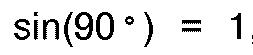

so that total internal reflection occurs, for two media having indices of refraction n₁ and n₂, when the angle of incidence just exceeds
This angle will obviously differ for each pair of media having different indices of refraction. - As an approximation to most of the optical grade materials that can be used in the present invention, glass has an index of refraction of approximately 1.5, while air has an index of refraction of approximately 1 (the index of refraction of a vacuum is exactly 1). Therefore, for light rays traveling in glass, total internal reflection occurs when the angle of incidence exceeds

- Thus for a light pipe of glass or an optical medium of similar index of refraction, only those light rays having angles of incidence of less than 41.8° would escape through the sides of the waveguide. If the direction of the light rays that enter through the entrance end of the light pipe are sufficiently well-controlled, one can almost guarantee that no light rays will escape before reaching the exit end. Only those light rays that enter at random angles (e.g., light rays from ambient sources) might be sufficiently close to being perpendicular to the side walls of the light pipe to escape. If the dimension of the light pipe perpendicular to the direction of desired transmission of light is small enough, only a small number of random light rays will escape near the entrance end of the light pipe.
- Previously known light pipes did not control the lateral distribution of the light passing through the light pipe. That is, for a light pipe of high aspect ratio -- much wider in a first direction perpendicular to the direction of light travel than it is in a second direction perpendicular to the direction of light travel, previously known vacuum cleaner light pipes did nothing to control the distribution of light in the first direction, or indeed to prevent the escape of light out the side walls in that direction. As a result, there was some leakage out the sides of previously known vacuum cleaner light pipes and, more importantly, light exiting the previously known light pipes tended to be concentrated at points along the width of the exit end that were directly opposite the points along the width of the entrance end at which the light sources were located.
- The present invention addresses these difficulties of high-aspect ratio light pipes by providing reflex optical elements on surfaces of the light pipe, using total internal reflection to increase control of light propagating through the light pipe. Reflex optical elements are optical elements that reflect light.
- In the present invention, the reflex optical elements are triangular prismatic elements arranged along lines extending substantially radially from a single point behind the entrance end of the light pipe. The light source of the vacuum cleaner is intended to be mounted at this virtual center point of the array of prismatic elements. The prismatic elements in the preferred embodiment have cross sections that are substantially isosceles right triangles, although they need not be. The apex angle of the prismatic elements is chosen so that in addition to preventing light from escaping from the light pipe, total internal reflection keeps light within the prismatic elements. The prismatic elements thereby become channels for collimating the light into a desired distribution at the front face of the light pipe. By shaping the entrance end so that light enters substantially uniformly across the entrance end, light can be directed to exit substantially uniformly across the exit end. In the case of a vacuum cleaner headlight, this results in more uniform lighting.
- A vacuum
cleaner assembly 10 incorporating alight pipe 40 according to the present invention is shown in FIGS. 1-3. As explained above, the present invention can be used in the motor-driven nozzle of a canister vacuum cleaner, or in the base of an upright vacuum cleaner; vacuumcleaner assembly 10 as shown in the drawings is a motor-driven nozzle. - Motor-driven
nozzle 10 has asuction chamber 20 housing a rotating (when operating)agitator brush 21.Brush 21 helps dislodge dirt from the surface to be cleaned, which is then sucked throughsuction passage 22 intoconnector 11, which connects to the wand and suction hose (neither shown) of a canister vacuum unit. Wheels 23 (one shown) make it easier to move motor-drivennozzle 10 over the surface to be cleaned.Power cord 12 provides power tomotor 30 which drivesbrush 21 viabelt 31.Switch 32 can be provided to turnmotor 30 on and off, depending on the nature of the surface to be cleaned (e.g., carpeted or not carpeted), and possibly to change the speed ofmotor 30.Light bulb 24 illuminates the surface to be cleaned throughlight pipe 40 in accordance with the invention. Areflector 25, which according to a preferred embodiment of the invention employs reflex optics, reflects light frombulb 24 throughlight pipe 40. Abumper strip 15 extends around the perimeter of motor-drivennozzle 10 to protect furniture and walls from impacts with motor-drivennozzle 10. - It is desirable for the
front 26 of motor-driven nozzle 10 (or of an upright vacuum cleaner base) to be as low as possible to maximize the utility of the vacuum cleaner for cleaning under furniture and beds.Suction chamber 20 contributes a certain minimum height, and a traditional headlight would add too much height for motor-drivennozzle 10 to be truly useful if the headlight were at thefront edge 26. And if the headlight were not at thefront edge 26,front edge 26 would cast a shadow in the surface to be cleaned that would prevent illumination of the immediate area to be cleaned. - Therefore, in accordance with the present invention,
light pipe 40, which is relatively thin, is provided to direct light outfront edge 26, withoutlight bulb 24 having to be oversuction chamber 20. -
Light pipe 40 is preferably made of an optical grade plastic such as polymethyl methacrylate, which has an index of refraction of about 1.489.Entrance end 33 oflight pipe 40 is preferably shaped to allow light rays frombulb 24 to enter easily intolight pipe 40. - The upper and
lower surfaces light pipe 40 bear a pattern of primary reflexprismatic elements 50 and secondary reflexprismatic elements 51. Primaryprismatic elements 50 preferably extend along lines that radiate from a point that is preferably centered on the filament ofbulb 24, and are provided to collimate and channel light uniformly frombulb 24 to thefront exit end 41 oflight pipe 40. That prevents a concentration of light directly in front ofbulb 24, spreading the light across the width oflight pipe 40. - The apex angle of primary
prismatic elements 50 is chosen with regard to the index of refraction of the material oflight pipe 40 and the desired channeling effect. If the apex angle is too small, the sides ofelements 50 will be too steep and light may escape, but if the apex angle is too large, the sides ofelements 50 may be too shallow to provide the desired channeling. In a particularly preferred embodiment, the apex angle is between about 89.5° and about 90.5°. - As
primary elements 50 extend away fromentrance end 33, because they are extending radially from a point, they diverge. If this divergence were not compensated for, it would result in gaps atexit end 41 between the ends of the variousprismatic elements 50. When the headlight was operating, such gaps would manifest themselves as dark, or dim, spots between the bright spots formed byelements 50. To eliminate such a pattern of alternating bright and dim spots, secondary reflexprismatic elements 51 are provided. - The cross section of secondary
prismatic elements 51 is preferably mathematically similar to that of primaryprismatic elements 50, with the same particularly preferred apex angle of between about 89.5° and about 90.5°. However, because secondaryprismatic elements 51 are designed to fill the increasingly wide gaps between primaryprismatic elements 50, the cross section of each secondaryprismatic element 51 preferably begins as substantially a point, and increases in size gradually, until it reachesexit end 41. (Actually, the cross section of each of primaryprismatic elements 50 also starts substantially as a point at its virtual origin, centered on the filament ofbulb 24, and increases as it extends towardexit end 41.) Secondaryprismatic elements 51 pick up light rays that stray into the voids between primaryprismatic elements 50 and direct them to exitend 41, resulting in a substantially uniformly bright illumination atexit end 41. -
Exit end 41 oflight pipe 40 is preferably formed at an incline, with the top further back than the bottom. This results in refraction of exiting light rays downward, so that the surface to be cleaned can be illuminated immediately in front of motor-drivennozzle 10. The angle of inclination in the preferred embodiment is about 17°. -
Light pipe 40 can be molded or otherwise formed as a single piece. However, especially when moldinglight pipe 40 from an optical grade plastic, it is advantageous to formlight pipe 40 in two pieces, i.e., an upper half-pipe 120 and a lower half-pipe 121, as best seen in FIG. 12 and FIGS. 6-8. Moldinglight pipe 40 as two half-pipes light pipe 40, as it is well known that a given volume cools faster as smaller pieces than as a single larger volume. Moreover, the two half-pipes - The
lower surface 122 of upper half-pipe 120 and theupper surface 123 of lower half-pipe 121 meet along partingplane 62. Preferably surfaces 122, 123 are perfectly smooth and flat and meet perfectly alongplane 62. However, it is acceptable if upper and lower half-pipes rear edges pipes edge bulb 24 may be visible to the user whenbulb 24 is illuminated. If half-pipes front edge 41, whether or not they meet atrear edge 33, there will be an unsightly gap. It is of little consequence, however, whether or notsurfaces plane 62, because, as long as eachsurface pipe surfaces - As best seen in FIG. 5, the horizontal cross section of upper half-
pipe 120 is not identical to that of lower half-pipe 121. Upper half-pipe 120 has indentation 52 atside 53.Indentation 52 is provided solely to enablelight pipe 40 to fit within the housing of motor-drivennozzle 10 without interfering with slopingsurface 13.Front face 41 of upper half-pipe 120 is extended overindentation 52. In a motor-driven nozzle of different design,indentation 52 may not be necessary. - Upper and lower half-
pipes sides pipes light pipe 40 that decrease the uniformity of light distribution. The most preferred method of fastening, however, is to provide posts on one of the half-pipes and corresponding holes in the other half-pipe (not shown). The posts are aligned to engage the holes in a press fit manner to hold the half-pipes together. Even where adhesive or clips are used, it may be advantageous to provide short posts and corresponding holes for alignment purposes. - In the preferred embodiment, as illustrated in the FIGURES, lower half-
pipe 121 has dependingflange 42.Flange 42 is provided solely for decorative purposes and in the illustrated embodiment is clear. As a result, when the headlight system is operating,bottom edge 43 offlange 42 is illuminated. It is also possible to provide other decorative treatments onflange 42, including ribs, grooves, matte stripes, etc. - Even with the provision of
prismatic elements end 33 may tend to stray outsides light pipe 40. That is particularly so in the case of certain ofelements bulb 24, terminate atside 53 orside 54, rather than atfront edge 41. Accordingly,light pipe 40 is preferably provided with supplemental reflexprismatic elements 100 atsides - Supplemental reflex
prismatic elements 100 are designed to capture, by total internal reflection, any such stray or misdirected light rays, and channel them either back into the body oflight pipe 40 or alongsides front exit edge 41. In the preferred embodiment having two half-pipes supplemental elements 100 are provided on the side edges of both half-pipes prismatic elements prismatic element 100 is preferably an isosceles triangle whose apex angle is chosen to assure the proper amount of internal reflection while still allowing the desired channeling. In a particularly preferred embodiment, the apex angle is between about 89.5° and about 90.5°. - Because
light pipe 40 does not extend across the full width of motor-drivennozzle 10, it would not ordinarily illuminate the entire surface immediately in front of motor-drivennozzle 10. In order to provide such illumination,exit edge 41 oflight pipe 40 is formed with prismatic shiftingelements 55, which are angled to refract exiting light rays, preferably by varying angular amounts, toward thearea 14 of motor-drivennozzle 10 to whichlight pipe 40 does not extend. Prismatic shiftingelements 55 preferably are of progressively smaller angle as one proceeds fromside 53 towardside 54. In the preferred embodiment, prismatic shiftingelements 55 are divided into nineteen groups. In that preferred embodiment, proceeding from group to group fromside 53 towardside 54, the prismangle facing side 54 increases from about 14.65° to about 75.0°, and proceeding fromside 54 toside 53, the prismangle facing side 53 ranges from about 15.0° to about 90.0°. The angles are chosen to assure thatarea 14 is illuminated, as well as to assure that areas not directly in front ofnozzle 10 are not needlessly illuminated. In addition, some of the groups near the center ofexit end 41 are preferably inclined at a greater angle than the approximately 17° inclination of the remaining groups, to provide more effective illumination of the surface to be cleaned immediately in front ofnozzle 10. - The effects of shifting
elements 55 are shown in FIG. 1, wherearea 16 represents the area that would be illuminated in the absence of shiftingelements 55, whilearea 17 represents the area illuminated when shiftingelements 55 are provided. - In the preferred embodiment of
light pipe 40 having upper and lower half-pipes elements 55 are provided on both half-pipes elements 55 on only one of half-pipes - As stated above, reflex
optical reflector 25 is provided to better utilize the light frombulb 24.Reflector 25 is made reflective by providing a plurality of prismatic reflectingelements 140 on the rear surface of reflector 25 (away from bulb 24), in place of the traditional metallization applied to such surfaces in conventional mirrors. This decreases the absorption caused by traditional metallization techniques such as vacuum metallization. All of the material ofreflector 25 is intrinsically transparent. However, the apex angle of each ofelements 140 is preferably chosen so that substantially all lightrays entering face 150 ofreflector 25 are reflected back towardbulb 24 andentrance edge 33 oflight pipe 40.Tabs 130 are provided for attachingreflector 25 to motor-drivennozzle 10. - The horizontal cross section of
face 150 is preferably a circular arc, most preferably a semicircle, substantially centered on the filament of bulb 24 (i.e., substantially the same virtual center point from whichelements reflector 25 should be part-spherical; however, with the dimensions involved in motor-drivennozzle 10, a part-cylindrical shape is a sufficient approximation. In this case, all light rays are impinging substantially normally onsurface 150 and continuing back toelements 140. It is desired that no light ray impinge on a side of anyelement 140 at less than 41.8° from the normal, or more than 48.2° from the surface of that side. Hence the preferred apex angle is no greater than 96.4° (twice 48.2°). The particularly preferred apex angle is between about 89.5° and about 90.5°. -
Reflector 25 increases the amount of light enteringlight pipe 40. The semicircular shape directs reflected light rays intolight pipe 40 at substantially the same angle as direct light frombulb 24. Accordingly, the available light is increased while the number of stray rays that would affect the uniformity of light distribution is minimized. - Thus it is seen that a vacuum cleaner headlight which does not excessively increase the height of the front of a vacuum cleaner, which illuminates the area immediately in front of the vacuum cleaner, and which has an effective distribution of light across the width of the vacuum cleaner, as well as a vacuum cleaner, incorporating a light pipe, which only requires one light pipe and one light bulb or other light source, are provided. One skilled in the art will appreciate that the present invention can be practiced by other than the described embodiments, which are presented for purposes of illustration and not of limitation, and the present invention is limited only by the claims which follow.
Claims (26)
- A light pipe (40) for use in a vacuum cleaner headlight assembly (10), which is wider in a first direction than a second direction, both directions being substantially perpendicular to a direction of propagation of light passing through the entry face (33) and exit face (41) of the light pipe (40), having primary reflex optical prismatic elements (50) on at least one surface (60,61) which extends between the entry and exit faces, each primary reflex optical prismatic element (50) defining an optical channel, the primary reflex optical prismatic elements (50) being spaced in the first direction across the at least one surface so as to channel light from the entry face (33) to regions spread across the exit face (41).
- A light pipe (40) according to claim 1 in which the primary prismatic elements (50) are arranged in a divergent array.
- A light pipe (40) according to claim 2 in which separation between primary prismatic elements (50) increases from the entry (33) to the exit face (41).
- A light pipe (40) according to claim 2 or 3 in which the primary prismatic elements (50) in the divergent array diverge substantially radially from a point outside the light pipe (40).
- A light pipe according to any preceding claim in which the cross section of the primary prismatic elements (50) increases with distance from the entry face (33) of the light pipe (40).
- A light pipe (40) according to any preceding claim further comprising secondary prismatic elements (51) disposed between the primary prismatic elements (50).
- A light pipe (40) according to claim 6 in which the cross section of the secondary prismatic elements (51) increases with distance from the entry face (33) of the light pipe (40).
- A light pipe (40) according to any preceding claim further comprising supplemental prismatic elements (100) disposed on at least one lateral side (53, 54) of the light pipe (40), the supplemental prismatic elements (100) positioned to reflect back into the light pipe (40) light rays which would otherwise exit laterally through the side (53, 54) of the light pipe (40).
- A light pipe (40) according to any preceding claim in which any of the prismatic elements (50), (51), (100) has an isosceles triangular cross section.
- A light pipe (40) according to claim 9 in which the apex angle of the isosceles triangular cross section is between 89.5° and 90.5°.
- A light pipe (40) according to any preceding claim further comprising a plurality of prismatic shifting elements (55) on the exit face (41) of the light pipe (40) for changing the direction of propagation of light rays passing through the exit face (41).
- A light pipe (40) according to claim 11 in which the direction of propagation of light rays passing through the exit face (41) is shifted laterally relative to the direction of propagation through a primary prismatic element (50).
- A light pipe (40) according to claim 11 or 12 in which the prismatic shifting elements (100) vary in size across the exit face (41) of the light pipe (40).
- A light pipe (40) according to claim 11, 12 or 13 in which each of the prismatic shifting element (100) has an apex angle, the prismatic shifting elements (100) varying in apex angle across the exit face (41) of the light pipe (40).
- A light pipe (40) according to any of claims 11 to 14 in which the lateral extent of the exit face (41) of the light pipe (40) is substantially covered by the prismatic shifting elements (100).
- A light pipe (40) according to any of the preceding claims in which the exit face (41) of the light pipe (40) is inclined to the plane of the light pipe (40).
- A light pipe (40) according to claim 16 in which the angle of inclination is about 17°.
- A light pipe (40) according to claim 16 in which portions of the exit face (41) of the light pipe (40) are inclined at a greater angle than other portions.
- A lighting assembly comprising a light pipe (40) in accordance with any preceding claim, and a light source (24), the light source (24) being positioned relative to the light pipe (40) such that the light from the light source (24) propagates through the light pipe (40) towards the exit face (41).
- A lighting assembly according to claim 19 when appendant on claim 3 in which the light source (24) is centred on the point of divergence of the primary prismatic elements (50).
- A lighting assembly according to claim 19 or 20 further comprising an optical reflector (25) spaced from the light source (24) in a first direction for reflecting light in a second direction opposite the first direction toward the entry face (33) of the light pipe (40), the optical reflector (25) comprising a substantially transparent part-cylindrical element whose axis is substantially centred on the light source (24), and a plurality of prismatic elements (140) arranged on the surface facing away from the light source (24) which extend substantially parallel to the axis of the part-cylindrical element.
- A lighting assembly according to claim 21 in which the prismatic elements (140) of the optical reflector (25) have an isosceles triangular cross section.
- A lighting assembly according to claim 22 in which the apex angle is less than 96.4°.
- A lighting assembly according to claim 22 or 23 in which the apex angle is between 89.5° and 90.5°.
- A lighting assembly according to any of claims 21 to 24 in which the surface facing away from the light source (24) is substantially covered by the prismatic elements (140).
- A vacuum cleaning headlight assembly (10) comprising a lighting assembly in accordance with any of claims 19 to 25, the lighting assembly being positioned such that the light source (24) is remote from the front wall (26) of the vacuum cleaner, with the light pipe (40) being disposed between the light source (24) and an aperture in the front wall (26) to channel light from the light source (24) through the aperture.
Applications Claiming Priority (2)
| Application Number | Priority Date | Filing Date | Title |
|---|---|---|---|
| US07/750,304 US5207498A (en) | 1991-08-27 | 1991-08-27 | Vacuum cleaner headlight |
| US750304 | 1991-08-27 |
Publications (2)
| Publication Number | Publication Date |
|---|---|
| EP0530026A1 EP0530026A1 (en) | 1993-03-03 |
| EP0530026B1 true EP0530026B1 (en) | 1995-11-08 |
Family
ID=25017307
Family Applications (1)
| Application Number | Title | Priority Date | Filing Date |
|---|---|---|---|
| EP92307826A Expired - Lifetime EP0530026B1 (en) | 1991-08-27 | 1992-08-27 | Vacuum cleaner headlight |
Country Status (8)
| Country | Link |
|---|---|
| US (1) | US5207498A (en) |
| EP (1) | EP0530026B1 (en) |
| JP (1) | JPH0815476B2 (en) |
| AU (1) | AU2087792A (en) |
| CA (1) | CA2075424C (en) |
| DE (1) | DE69205926T2 (en) |
| ES (1) | ES2082380T3 (en) |
| MX (1) | MX9204938A (en) |
Families Citing this family (48)
| Publication number | Priority date | Publication date | Assignee | Title |
|---|---|---|---|---|
| USD349371S (en) | 1992-01-10 | 1994-08-02 | Trc Acquisition Corporation | Base for an upright vacuum cleaner |
| CA2108876C (en) * | 1993-01-25 | 1996-04-09 | Arnold L. Sepke | Vacuum cleaner with illuminated belt view |
| US5381508A (en) * | 1993-08-25 | 1995-01-10 | Krumenacher; Paul F. | Suction and light guide assembly |
| ITMO940022A1 (en) * | 1994-02-22 | 1995-08-22 | Giancarlo Fini | GENERAL SURFACE CLEANING TOOL |
| US5481637A (en) * | 1994-11-02 | 1996-01-02 | The University Of British Columbia | Hollow light guide for diffuse light |
| KR100208128B1 (en) * | 1996-04-13 | 1999-07-15 | 최진호 | Vacuum cleaner |
| USD392779S (en) | 1996-07-22 | 1998-03-24 | The Scott Fetzer Company | Headlight cap assembly for vacuum cleaner or similar article |
| JP2997229B2 (en) * | 1996-09-10 | 2000-01-11 | 三星光州電子株式会社 | Vacuum cleaner |
| US6256833B1 (en) | 1999-01-20 | 2001-07-10 | Bissell Homecare, Inc. | Upright vacuum cleaner with handle-mounted lamp assembly and height adjustment |
| MXPA03002383A (en) * | 2000-09-18 | 2003-10-15 | Ecolab Inc | Portable radiation cure device. |
| US6499183B1 (en) * | 2000-09-29 | 2002-12-31 | Oreck Holdings, Llc | Low-profile and highly-maneuverable vacuum cleaner having a headlight, a sidelight, anti-ingestion bars, side brushes, a squeegee, and a scent cartridge |
| US6493903B1 (en) | 2001-05-18 | 2002-12-17 | Quest Industries, Inc. | Hand-held vacuum cleaner with headlamp |
| AU2003303200A1 (en) * | 2002-12-18 | 2004-07-14 | Matsushita Electric Corporation Of America | Lighted wand assembly |
| US7331083B2 (en) * | 2002-12-18 | 2008-02-19 | Panasonic Corporation Of North America | Lighted wand assembly with remote light source |
| DE10353456A1 (en) * | 2003-11-15 | 2005-06-16 | Düpro AG | Cleaning tool for floor surfaces with a work area lighting |
| USD522198S1 (en) | 2004-04-30 | 2006-05-30 | Proteam, Inc. | Vacuum cleaner nozzle |
| US6856113B1 (en) | 2004-05-12 | 2005-02-15 | Cube Investments Limited | Central vacuum cleaning system motor control circuit mounting post, mounting configuration, and mounting methods |
| CA2580282C (en) * | 2004-09-17 | 2014-04-15 | Cube Investments Limited | Cleaner handle and cleaner handle housing sections |
| US20060096057A1 (en) * | 2004-11-08 | 2006-05-11 | Chatfield Dean M | Illumination accessory assembly for vacuum cleaner |
| US20060215390A1 (en) * | 2005-03-24 | 2006-09-28 | Jones Terry G | Lighted cleaning implement |
| US8732895B2 (en) * | 2005-10-07 | 2014-05-27 | Cube Investments Limited | Central vacuum cleaner multiple vacuum source control |
| US7690075B2 (en) | 2005-10-07 | 2010-04-06 | Cube Investments Limited | Central vacuum cleaner control, unit and system with contaminant sensor |
| US7900315B2 (en) * | 2005-10-07 | 2011-03-08 | Cube Investments Limited | Integrated central vacuum cleaner suction device and control |
| CA2562804C (en) | 2005-10-07 | 2014-12-09 | Cube Investments Limited | Vacuum cleaner cross-control |
| US7328479B2 (en) * | 2006-04-13 | 2008-02-12 | Electrolux Home Care Products Ltd. | Lighting apparatus for a vacuum cleaner |
| US20080127447A1 (en) * | 2006-11-30 | 2008-06-05 | Overaag Chad D | Floor care apparatus equipped with electroluminescent light source |
| US7627927B2 (en) | 2007-06-08 | 2009-12-08 | Tacony Corporation | Vacuum cleaner with sensing system |
| WO2009002907A2 (en) * | 2007-06-22 | 2008-12-31 | Electrolux Home Care Products, Inc. | Vacuum cleaner nozzle height indicator |
| US20090059569A1 (en) * | 2007-08-29 | 2009-03-05 | Quattrini Jr Richard J | Hand pushed floor cleaning tool with an integrated illumination source |
| US20090059590A1 (en) * | 2007-08-29 | 2009-03-05 | Quattrini Jr Richard J | Portable surface skimming illumination device for locating small items on a planar surface |
| US7736008B2 (en) * | 2007-08-30 | 2010-06-15 | Quattrini Jr Richard J | Dustpan with an integrated illumination source |
| US8214968B2 (en) | 2008-01-17 | 2012-07-10 | Bissell Homecare, Inc. | Vacuum accessory tool |
| US20100238661A1 (en) * | 2009-03-20 | 2010-09-23 | Sylvan R. Shemitz Designs Incorporated | Asymmetrical light producing baffle and luminaire inclusive thereof |
| JP5899427B2 (en) * | 2012-04-17 | 2016-04-06 | パナソニックIpマネジメント株式会社 | Vacuum cleaner suction tool and vacuum cleaner using the same |
| JP2013220206A (en) * | 2012-04-17 | 2013-10-28 | Panasonic Corp | Suction tool for vacuum cleaner and the vacuum cleaner using the same |
| FR3003744B1 (en) * | 2013-03-26 | 2015-09-04 | Seb Sa | VACUUM SQUEEGEE COMPRISING A LIGHT SOURCE |
| CN103479299A (en) * | 2013-09-17 | 2014-01-01 | 无锡莱吉特信息科技有限公司 | Dust collector sucker capable of lighting |
| JP6459424B2 (en) * | 2014-07-23 | 2019-01-30 | パナソニックIpマネジメント株式会社 | Vacuum cleaner and its suction tool |
| USD781514S1 (en) | 2014-07-29 | 2017-03-14 | Electrolux Home Care Products, Inc. | Vacuum cleaner nozzle hood |
| USD778517S1 (en) | 2014-07-29 | 2017-02-07 | Electrolux Home Care Products, Inc. | Vacuum cleaner nozzle hood |
| JP6689000B2 (en) | 2014-11-10 | 2020-04-28 | パナソニックIpマネジメント株式会社 | Lighting device for vacuum cleaner |
| JP6358438B2 (en) * | 2015-01-20 | 2018-07-18 | パナソニックIpマネジメント株式会社 | Display illumination device and electric vacuum cleaner provided with the same |
| GB2600656B (en) * | 2018-10-02 | 2022-10-05 | Sharkninja Operating Llc | Surface cleaning apparatus illumination system |
| DE102019117761A1 (en) * | 2019-07-02 | 2019-10-17 | Miele & Cie. Kg | Floor nozzle and vacuum cleaner |
| US11617486B2 (en) | 2019-11-25 | 2023-04-04 | Bissell Inc. | Surface cleaning apparatus with task lighting |
| CN212913072U (en) * | 2020-06-09 | 2021-04-09 | 天佑电器(苏州)有限公司 | Floor brush for dust collector and dust collector |
| JP7517932B2 (en) * | 2020-09-28 | 2024-07-17 | 日立グローバルライフソリューションズ株式会社 | Suction nozzle of vacuum cleaner and vacuum cleaner equipped with same |
| US20250326011A1 (en) * | 2024-04-22 | 2025-10-23 | Emerson Professional Tool, LLC | Drain cleaners with a top-mounted light assembly |
Family Cites Families (29)
| Publication number | Priority date | Publication date | Assignee | Title |
|---|---|---|---|---|
| US1028721A (en) * | 1910-08-16 | 1912-06-04 | A H Heisey & Co Inc | Illuminator. |
| US2208523A (en) * | 1936-09-03 | 1940-07-16 | Lenslite Co Inc | Sighting means for suction cleaners |
| US2217174A (en) * | 1937-04-30 | 1940-10-08 | Singer Mfg Co | Vacuum cleaner |
| US2274971A (en) * | 1939-04-24 | 1942-03-03 | Hoover Co | Suction cleaner |
| US2471800A (en) * | 1943-07-19 | 1949-05-31 | Mulinen Egbert Von | Shadow image projection indicating apparatus |
| US2480178A (en) * | 1946-05-08 | 1949-08-30 | Ivan H Zinberg | Light conductor |
| US2475400A (en) * | 1947-04-23 | 1949-07-05 | Eureka Williams Corp | Hood for suction cleaners and the like |
| US2673288A (en) * | 1948-10-12 | 1954-03-23 | Westinghouse Brake & Signal | Reflector for the production of light beams |
| US2730750A (en) * | 1951-05-05 | 1956-01-17 | Hoover Co | Low height suction cleaner arrangement |
| US2737573A (en) * | 1953-10-28 | 1956-03-06 | Gen Electric | Lighting means for automatic clothes washers |
| US3278738A (en) * | 1964-01-02 | 1966-10-11 | Bausch & Lomb | Light deflector |
| US3546438A (en) * | 1967-05-25 | 1970-12-08 | Farrington Electronics Inc | Illumination system |
| US3619591A (en) * | 1970-02-19 | 1971-11-09 | Gen Dynamics Corp | Illuminated pushbuttons using piped light |
| US4282560A (en) * | 1979-01-15 | 1981-08-04 | A.C.A. Products, Inc. | Light distributor |
| US4322781A (en) * | 1980-07-03 | 1982-03-30 | The Singer Company | Uniformly lighted pattern display |
| JPS5768801A (en) * | 1980-10-17 | 1982-04-27 | Fuji Photo Optical Co Ltd | Linear lighting equipment |
| US4528617A (en) * | 1982-02-08 | 1985-07-09 | Sheltered Workshop For The Disabled, Inc. | Light distribution apparatus |
| EP0167721B1 (en) * | 1984-07-02 | 1989-10-11 | Mitsubishi Rayon Co., Ltd. | Light diffuser |
| JPS6134583A (en) * | 1984-07-26 | 1986-02-18 | シャープ株式会社 | Lighting apparatus |
| US4805984A (en) * | 1985-11-21 | 1989-02-21 | Minnesota Mining And Manufacturing Company | Totally internally reflecting light conduit |
| US4716507A (en) * | 1986-05-12 | 1987-12-29 | The United States Of America As Represented By The Secretary Of The Army | Optical collimator target illumination |
| US4834495A (en) * | 1987-05-08 | 1989-05-30 | Minnesota Mining And Manufacturing Company | Collapsible light pipe |
| US5107565A (en) * | 1987-05-22 | 1992-04-28 | Whirlpool Corporation | Light system for vacuum cleaner |
| US4791700A (en) * | 1987-12-29 | 1988-12-20 | The Scott Fetzer Company | Fresnel lens illuminator for vacuum cleaner |
| US4757574A (en) * | 1988-01-25 | 1988-07-19 | The Singer Company | Light plate for vacuum cleaner |
| US4991918A (en) * | 1988-03-03 | 1991-02-12 | Eastman Kodak Company | Light collector for stimulable phosphor imaging apparatus |
| US4996632A (en) * | 1988-10-07 | 1991-02-26 | Gulton Industries, Inc. | Multi-color illuminating system |
| US5005108A (en) * | 1989-02-10 | 1991-04-02 | Lumitex, Inc. | Thin panel illuminator |
| US5009475A (en) * | 1989-12-27 | 1991-04-23 | Advance Display Technologies, Inc. | Image transfer device and method of manufacture |
-
1991
- 1991-08-27 US US07/750,304 patent/US5207498A/en not_active Expired - Lifetime
-
1992
- 1992-08-06 CA CA002075424A patent/CA2075424C/en not_active Expired - Lifetime
- 1992-08-07 AU AU20877/92A patent/AU2087792A/en not_active Abandoned
- 1992-08-27 MX MX9204938A patent/MX9204938A/en not_active IP Right Cessation
- 1992-08-27 ES ES92307826T patent/ES2082380T3/en not_active Expired - Lifetime
- 1992-08-27 DE DE69205926T patent/DE69205926T2/en not_active Expired - Fee Related
- 1992-08-27 EP EP92307826A patent/EP0530026B1/en not_active Expired - Lifetime
- 1992-08-27 JP JP4228362A patent/JPH0815476B2/en not_active Expired - Lifetime
Also Published As
| Publication number | Publication date |
|---|---|
| ES2082380T3 (en) | 1996-03-16 |
| EP0530026A1 (en) | 1993-03-03 |
| DE69205926T2 (en) | 1996-07-04 |
| US5207498A (en) | 1993-05-04 |
| AU2087792A (en) | 1993-03-04 |
| JPH05192281A (en) | 1993-08-03 |
| MX9204938A (en) | 1993-04-01 |
| CA2075424A1 (en) | 1993-02-28 |
| CA2075424C (en) | 1997-09-30 |
| JPH0815476B2 (en) | 1996-02-21 |
| DE69205926D1 (en) | 1995-12-14 |
Similar Documents
| Publication | Publication Date | Title |
|---|---|---|
| US5207498A (en) | Vacuum cleaner headlight | |
| CA1316161C (en) | Light fixture providing normalized output | |
| US5107565A (en) | Light system for vacuum cleaner | |
| US5165772A (en) | Visual display device | |
| US5590945A (en) | Illuminated line of light using point light source | |
| US5444606A (en) | Prismatic reflector and prismatic lens | |
| US6367950B1 (en) | Vehicle lamp fixture and method of use | |
| US6474826B1 (en) | Lighting apparatus | |
| JP2002525791A (en) | Lighting equipment | |
| JP6689000B2 (en) | Lighting device for vacuum cleaner | |
| CN1220002A (en) | Illumination system comprising microprisms with blocking means | |
| EP0453092A1 (en) | Uniform illumination of large, thin surfaces particularly suited for automotive applications | |
| US4510560A (en) | Device for controlling light images | |
| US6867826B2 (en) | Lighting panel for a display | |
| JP3567819B2 (en) | Light distribution control panel and equipment using it | |
| CN118896273A (en) | Lamp with optical device and lighting light guide | |
| ES2255737T3 (en) | WAVE GUIDE STRUCTURES FOR VEHICLE LIGHTING. | |
| CN217209199U (en) | Lighting lens of high-ceiling lamp for corridor passage | |
| JPH06342159A (en) | Surface light source and method for manufacturing surface light source | |
| US5791772A (en) | Lamp assembly with light pipe, light pipe and light pipe/lens assembly | |
| WO1990010823A1 (en) | Light diffuser | |
| JPH0232320A (en) | Back lighting device | |
| JPH09258029A (en) | Lighting equipment | |
| JPH0572593U (en) | Car light lighting grill | |
| JPH09101520A (en) | LCD backlight device |
Legal Events
| Date | Code | Title | Description |
|---|---|---|---|
| PUAI | Public reference made under article 153(3) epc to a published international application that has entered the european phase |
Free format text: ORIGINAL CODE: 0009012 |
|
| AK | Designated contracting states |
Kind code of ref document: A1 Designated state(s): BE DE DK ES FR GB GR IE IT LU NL PT |
|
| 17P | Request for examination filed |
Effective date: 19930303 |
|
| 17Q | First examination report despatched |
Effective date: 19940329 |
|
| RAP1 | Party data changed (applicant data changed or rights of an application transferred) |
Owner name: ELECTROLUX CORPORATION |
|
| GRAA | (expected) grant |
Free format text: ORIGINAL CODE: 0009210 |
|
| AK | Designated contracting states |
Kind code of ref document: B1 Designated state(s): BE DE DK ES FR GB GR IE IT LU NL PT |
|
| PG25 | Lapsed in a contracting state [announced via postgrant information from national office to epo] |
Ref country code: GR Free format text: LAPSE BECAUSE OF FAILURE TO SUBMIT A TRANSLATION OF THE DESCRIPTION OR TO PAY THE FEE WITHIN THE PRESCRIBED TIME-LIMIT Effective date: 19951108 Ref country code: DK Effective date: 19951108 Ref country code: BE Effective date: 19951108 |
|
| REG | Reference to a national code |
Ref country code: IE Ref legal event code: FG4D Free format text: 66057 |
|
| REF | Corresponds to: |
Ref document number: 69205926 Country of ref document: DE Date of ref document: 19951214 |
|
| ITF | It: translation for a ep patent filed | ||
| ET | Fr: translation filed | ||
| REG | Reference to a national code |
Ref country code: ES Ref legal event code: FG2A Ref document number: 2082380 Country of ref document: ES Kind code of ref document: T3 |
|
| PG25 | Lapsed in a contracting state [announced via postgrant information from national office to epo] |
Ref country code: IE Free format text: LAPSE BECAUSE OF NON-PAYMENT OF DUE FEES Effective date: 19960827 |
|
| PG25 | Lapsed in a contracting state [announced via postgrant information from national office to epo] |
Ref country code: LU Free format text: LAPSE BECAUSE OF NON-PAYMENT OF DUE FEES Effective date: 19960831 |
|
| PLBE | No opposition filed within time limit |
Free format text: ORIGINAL CODE: 0009261 |
|
| STAA | Information on the status of an ep patent application or granted ep patent |
Free format text: STATUS: NO OPPOSITION FILED WITHIN TIME LIMIT |
|
| 26N | No opposition filed | ||
| PGFP | Annual fee paid to national office [announced via postgrant information from national office to epo] |
Ref country code: ES Payment date: 19970806 Year of fee payment: 6 |
|
| PGFP | Annual fee paid to national office [announced via postgrant information from national office to epo] |
Ref country code: GB Payment date: 19970822 Year of fee payment: 6 |
|
| PGFP | Annual fee paid to national office [announced via postgrant information from national office to epo] |
Ref country code: FR Payment date: 19970829 Year of fee payment: 6 |
|
| PGFP | Annual fee paid to national office [announced via postgrant information from national office to epo] |
Ref country code: NL Payment date: 19970831 Year of fee payment: 6 |
|
| PGFP | Annual fee paid to national office [announced via postgrant information from national office to epo] |
Ref country code: DE Payment date: 19971030 Year of fee payment: 6 |
|
| PG25 | Lapsed in a contracting state [announced via postgrant information from national office to epo] |
Ref country code: GB Free format text: LAPSE BECAUSE OF NON-PAYMENT OF DUE FEES Effective date: 19980827 |
|
| PG25 | Lapsed in a contracting state [announced via postgrant information from national office to epo] |
Ref country code: ES Free format text: THE PATENT HAS BEEN ANNULLED BY A DECISION OF A NATIONAL AUTHORITY Effective date: 19980828 |
|
| PG25 | Lapsed in a contracting state [announced via postgrant information from national office to epo] |
Ref country code: NL Free format text: LAPSE BECAUSE OF NON-PAYMENT OF DUE FEES Effective date: 19990301 |
|
| GBPC | Gb: european patent ceased through non-payment of renewal fee |
Effective date: 19980827 |
|
| PG25 | Lapsed in a contracting state [announced via postgrant information from national office to epo] |
Ref country code: FR Free format text: LAPSE BECAUSE OF NON-PAYMENT OF DUE FEES Effective date: 19990430 |
|
| NLV4 | Nl: lapsed or anulled due to non-payment of the annual fee |
Effective date: 19990301 |
|
| PG25 | Lapsed in a contracting state [announced via postgrant information from national office to epo] |
Ref country code: DE Free format text: LAPSE BECAUSE OF NON-PAYMENT OF DUE FEES Effective date: 19990601 |
|
| REG | Reference to a national code |
Ref country code: FR Ref legal event code: ST |
|
| REG | Reference to a national code |
Ref country code: ES Ref legal event code: FD2A Effective date: 20001204 |
|
| PG25 | Lapsed in a contracting state [announced via postgrant information from national office to epo] |
Ref country code: IT Free format text: LAPSE BECAUSE OF NON-PAYMENT OF DUE FEES Effective date: 20050827 |
|
| PG25 | Lapsed in a contracting state [announced via postgrant information from national office to epo] |
Ref country code: PT Free format text: LAPSE BECAUSE OF NON-PAYMENT OF DUE FEES Effective date: 19960408 |