EP0529676B1 - Induction system for an internal combustion engine - Google Patents
Induction system for an internal combustion engine Download PDFInfo
- Publication number
- EP0529676B1 EP0529676B1 EP92114868A EP92114868A EP0529676B1 EP 0529676 B1 EP0529676 B1 EP 0529676B1 EP 92114868 A EP92114868 A EP 92114868A EP 92114868 A EP92114868 A EP 92114868A EP 0529676 B1 EP0529676 B1 EP 0529676B1
- Authority
- EP
- European Patent Office
- Prior art keywords
- valve
- intake passage
- intake
- engine
- control valve
- Prior art date
- Legal status (The legal status is an assumption and is not a legal conclusion. Google has not performed a legal analysis and makes no representation as to the accuracy of the status listed.)
- Expired - Lifetime
Links
Images


Classifications
-
- F—MECHANICAL ENGINEERING; LIGHTING; HEATING; WEAPONS; BLASTING
- F02—COMBUSTION ENGINES; HOT-GAS OR COMBUSTION-PRODUCT ENGINE PLANTS
- F02M—SUPPLYING COMBUSTION ENGINES IN GENERAL WITH COMBUSTIBLE MIXTURES OR CONSTITUENTS THEREOF
- F02M35/00—Combustion-air cleaners, air intakes, intake silencers, or induction systems specially adapted for, or arranged on, internal-combustion engines
- F02M35/10—Air intakes; Induction systems
- F02M35/10006—Air intakes; Induction systems characterised by the position of elements of the air intake system in direction of the air intake flow, i.e. between ambient air inlet and supply to the combustion chamber
- F02M35/10078—Connections of intake systems to the engine
- F02M35/10085—Connections of intake systems to the engine having a connecting piece, e.g. a flange, between the engine and the air intake being foreseen with a throttle valve, fuel injector, mixture ducts or the like
-
- F—MECHANICAL ENGINEERING; LIGHTING; HEATING; WEAPONS; BLASTING
- F01—MACHINES OR ENGINES IN GENERAL; ENGINE PLANTS IN GENERAL; STEAM ENGINES
- F01L—CYCLICALLY OPERATING VALVES FOR MACHINES OR ENGINES
- F01L3/00—Lift-valve, i.e. cut-off apparatus with closure members having at least a component of their opening and closing motion perpendicular to the closing faces; Parts or accessories thereof
- F01L3/06—Valve members or valve-seats with means for guiding or deflecting the medium controlled thereby, e.g. producing a rotary motion of the drawn-in cylinder charge
-
- F—MECHANICAL ENGINEERING; LIGHTING; HEATING; WEAPONS; BLASTING
- F02—COMBUSTION ENGINES; HOT-GAS OR COMBUSTION-PRODUCT ENGINE PLANTS
- F02B—INTERNAL-COMBUSTION PISTON ENGINES; COMBUSTION ENGINES IN GENERAL
- F02B31/00—Modifying induction systems for imparting a rotation to the charge in the cylinder
- F02B31/04—Modifying induction systems for imparting a rotation to the charge in the cylinder by means within the induction channel, e.g. deflectors
- F02B31/06—Movable means, e.g. butterfly valves
- F02B31/08—Movable means, e.g. butterfly valves having multiple air inlets, i.e. having main and auxiliary intake passages
- F02B31/085—Movable means, e.g. butterfly valves having multiple air inlets, i.e. having main and auxiliary intake passages having two inlet valves
-
- F—MECHANICAL ENGINEERING; LIGHTING; HEATING; WEAPONS; BLASTING
- F02—COMBUSTION ENGINES; HOT-GAS OR COMBUSTION-PRODUCT ENGINE PLANTS
- F02D—CONTROLLING COMBUSTION ENGINES
- F02D9/00—Controlling engines by throttling air or fuel-and-air induction conduits or exhaust conduits
- F02D9/08—Throttle valves specially adapted therefor; Arrangements of such valves in conduits
- F02D9/12—Throttle valves specially adapted therefor; Arrangements of such valves in conduits having slidably-mounted valve members; having valve members movable longitudinally of conduit
- F02D9/16—Throttle valves specially adapted therefor; Arrangements of such valves in conduits having slidably-mounted valve members; having valve members movable longitudinally of conduit the members being rotatable
-
- F—MECHANICAL ENGINEERING; LIGHTING; HEATING; WEAPONS; BLASTING
- F02—COMBUSTION ENGINES; HOT-GAS OR COMBUSTION-PRODUCT ENGINE PLANTS
- F02F—CYLINDERS, PISTONS OR CASINGS, FOR COMBUSTION ENGINES; ARRANGEMENTS OF SEALINGS IN COMBUSTION ENGINES
- F02F1/00—Cylinders; Cylinder heads
- F02F1/24—Cylinder heads
- F02F1/42—Shape or arrangement of intake or exhaust channels in cylinder heads
- F02F1/4214—Shape or arrangement of intake or exhaust channels in cylinder heads specially adapted for four or more valves per cylinder
-
- F—MECHANICAL ENGINEERING; LIGHTING; HEATING; WEAPONS; BLASTING
- F02—COMBUSTION ENGINES; HOT-GAS OR COMBUSTION-PRODUCT ENGINE PLANTS
- F02M—SUPPLYING COMBUSTION ENGINES IN GENERAL WITH COMBUSTIBLE MIXTURES OR CONSTITUENTS THEREOF
- F02M35/00—Combustion-air cleaners, air intakes, intake silencers, or induction systems specially adapted for, or arranged on, internal-combustion engines
- F02M35/10—Air intakes; Induction systems
- F02M35/10209—Fluid connections to the air intake system; their arrangement of pipes, valves or the like
- F02M35/10216—Fuel injectors; Fuel pipes or rails; Fuel pumps or pressure regulators
-
- F—MECHANICAL ENGINEERING; LIGHTING; HEATING; WEAPONS; BLASTING
- F02—COMBUSTION ENGINES; HOT-GAS OR COMBUSTION-PRODUCT ENGINE PLANTS
- F02M—SUPPLYING COMBUSTION ENGINES IN GENERAL WITH COMBUSTIBLE MIXTURES OR CONSTITUENTS THEREOF
- F02M35/00—Combustion-air cleaners, air intakes, intake silencers, or induction systems specially adapted for, or arranged on, internal-combustion engines
- F02M35/10—Air intakes; Induction systems
- F02M35/10242—Devices or means connected to or integrated into air intakes; Air intakes combined with other engine or vehicle parts
- F02M35/10262—Flow guides, obstructions, deflectors or the like
-
- F—MECHANICAL ENGINEERING; LIGHTING; HEATING; WEAPONS; BLASTING
- F02—COMBUSTION ENGINES; HOT-GAS OR COMBUSTION-PRODUCT ENGINE PLANTS
- F02M—SUPPLYING COMBUSTION ENGINES IN GENERAL WITH COMBUSTIBLE MIXTURES OR CONSTITUENTS THEREOF
- F02M35/00—Combustion-air cleaners, air intakes, intake silencers, or induction systems specially adapted for, or arranged on, internal-combustion engines
- F02M35/10—Air intakes; Induction systems
- F02M35/104—Intake manifolds
- F02M35/108—Intake manifolds with primary and secondary intake passages
- F02M35/1085—Intake manifolds with primary and secondary intake passages the combustion chamber having multiple intake valves
-
- F—MECHANICAL ENGINEERING; LIGHTING; HEATING; WEAPONS; BLASTING
- F02—COMBUSTION ENGINES; HOT-GAS OR COMBUSTION-PRODUCT ENGINE PLANTS
- F02M—SUPPLYING COMBUSTION ENGINES IN GENERAL WITH COMBUSTIBLE MIXTURES OR CONSTITUENTS THEREOF
- F02M35/00—Combustion-air cleaners, air intakes, intake silencers, or induction systems specially adapted for, or arranged on, internal-combustion engines
- F02M35/10—Air intakes; Induction systems
- F02M35/104—Intake manifolds
- F02M35/112—Intake manifolds for engines with cylinders all in one line
-
- F—MECHANICAL ENGINEERING; LIGHTING; HEATING; WEAPONS; BLASTING
- F02—COMBUSTION ENGINES; HOT-GAS OR COMBUSTION-PRODUCT ENGINE PLANTS
- F02B—INTERNAL-COMBUSTION PISTON ENGINES; COMBUSTION ENGINES IN GENERAL
- F02B2275/00—Other engines, components or details, not provided for in other groups of this subclass
- F02B2275/18—DOHC [Double overhead camshaft]
-
- F—MECHANICAL ENGINEERING; LIGHTING; HEATING; WEAPONS; BLASTING
- F02—COMBUSTION ENGINES; HOT-GAS OR COMBUSTION-PRODUCT ENGINE PLANTS
- F02B—INTERNAL-COMBUSTION PISTON ENGINES; COMBUSTION ENGINES IN GENERAL
- F02B2275/00—Other engines, components or details, not provided for in other groups of this subclass
- F02B2275/48—Tumble motion in gas movement in cylinder
-
- F—MECHANICAL ENGINEERING; LIGHTING; HEATING; WEAPONS; BLASTING
- F02—COMBUSTION ENGINES; HOT-GAS OR COMBUSTION-PRODUCT ENGINE PLANTS
- F02F—CYLINDERS, PISTONS OR CASINGS, FOR COMBUSTION ENGINES; ARRANGEMENTS OF SEALINGS IN COMBUSTION ENGINES
- F02F1/00—Cylinders; Cylinder heads
- F02F1/24—Cylinder heads
- F02F2001/244—Arrangement of valve stems in cylinder heads
- F02F2001/245—Arrangement of valve stems in cylinder heads the valve stems being orientated at an angle with the cylinder axis
-
- Y—GENERAL TAGGING OF NEW TECHNOLOGICAL DEVELOPMENTS; GENERAL TAGGING OF CROSS-SECTIONAL TECHNOLOGIES SPANNING OVER SEVERAL SECTIONS OF THE IPC; TECHNICAL SUBJECTS COVERED BY FORMER USPC CROSS-REFERENCE ART COLLECTIONS [XRACs] AND DIGESTS
- Y02—TECHNOLOGIES OR APPLICATIONS FOR MITIGATION OR ADAPTATION AGAINST CLIMATE CHANGE
- Y02T—CLIMATE CHANGE MITIGATION TECHNOLOGIES RELATED TO TRANSPORTATION
- Y02T10/00—Road transport of goods or passengers
- Y02T10/10—Internal combustion engine [ICE] based vehicles
- Y02T10/12—Improving ICE efficiencies
Definitions
- This invention relates to an induction system for an internal combustion engine having a cylinder head and a cylinder block, said cylinder head at least partially defining a combustion chamber, and an intake passage arrangement for each cylinder to serve a plurality of intake valves, with a main throttle valve arrangement being provided at an upstream side of the intake passage arrangement.
- Swirl is a flow of the charge in the combustion chamber in a generally circumferential direction around the axis of the cylinder. Swirl is generally generated by use of swirl ports in the induction system. However, the generation of swirl can reduce the volumetric efficiency at high speed. This is because swirl ports have higher flow resistance than non-swirl ports. In addition, there are some phases of running of the engine when swirl is not desirable even though some form of motion of the charge in the chamber is desirable.
- Tumble is a swirling motion of the intake charge about an axis that generally extends transversely to the cylinder bore axis. With such a flow arrangement, the charge tends to flow across the cylinder head, down one side of the cylinder bore, back across the cylinder bore across the top of the head of the piston and then up the other side of the cylinder bore back to the cylinder head with this flow pattern repeating.
- This type of motion also requires the formation of a specially formed port which will provide flow resistance and reduce volumetric efficiency under high speed. Like swirl, tumble is more effective at some speed than other speeds.
- One way in which the flow pattern in the combustion chamber can be varied under varying speed and load conditions is to provide a control valve in the induction passage that changes the effective configuration of the induction passage as the control valve is moved.
- the control valve can then be moved in response to varying speed and load conditions so as to provide the desired flow pattern.
- Such arrangements however, as previously proposed have only permitted the establishment of either one type of swirling motion (either swirl or tumble) or substantially no turbulence.
- One technique for changing the flow pattern from an intake passage in an internal combustion engine employs an additional passage that intersects the main intake passage upstream of the valve seat and through which another higher velocity flow is established.
- This can be done through the provision of a control valve but if another control valve is also employed for changing the effective configuration of the port, then the engine becomes very complicated.
- it may be physically impossible to employ two such valves in the cylinder head of an engine, where the intake port is normally formed.
- one way in which the flow patten within a combustion chamber may he altered is by providing a control valve that operates in the intake passage of the engine.
- a control valve that operates in the intake passage of the engine.
- some obstruction to the flow through the intake passage may occur. This can be either by direct flow resistance of the valve or a mounting portion of it extending into the induction passage even when the valve is fully opened.
- the control valve in its fully open position or some portion associated with it can give rise to a less than smooth intake passage which will induce turbulence within the intake passage itself and, accordingly, adversely effect volumetric efficiency.
- US 4 317 438 shows an induction system of the above-mentioned type.
- This induction system is, however, unsatisfactory, as it has the above-mentioned drawbacks such as an unwanted flow resistance for some running conditions.
- the intake passage arrangement is controlled by an intake air control valve for varying the cross section of the flow passage area of said intake passage arrangement, which is rotatably supported at the lower side of the intake passage arrangement in the cylinder head, the engine being considered in an upright position with the cylinder head at the top of it, the axis of the control valve extends transversely to the flow path of an intake charge flowing through the intake passage arrangement and in the direction of the axis of an overhead camshaft, said control valve being disposed at least in the vicinity of an end portion of the intake passage close to the combustion chamber, and in that, an auxiliary throttle valve is disposed between the main throttle valve and the control valve to control at least a part of the cross section of the intake passage arrangement, said auxiliary throttle valve being designed to prevent an obstruction of at least a part of the cross section of the intake passage irrespective of the angular position of the auxiliary throttle valve, but to obstruct the flow through a remainder part of the cross section of the intake passage
- the induction system according to the present invention has the advantageous effect that, while the intake air amount is small, as is for example the case during the low to medium speed engine operating range, the auxiliary throttle valve partly closes the intake passage or primary and secondary sub-intake passages of a Siamese type intake passage arrangement, leaving only the remaining intake passage or sub-intake passage open and the intake air control valve is rotated to its closed position and throttles that intake passage or sub-intake passage on the bottom valve side of the flow passage which was left open by the auxiliary throttle valve. Under such a condition, the intake air flows along one side through the intake passage or one of the primary or secondary sub-intake passages on the side left open by the auxiliary throttle valve and in a one-sided orientation along the ceiling wall side of the intake passage.
- a valve operating control system is provided to operate said control valve, which, most preferably, is disposed at a bight of the respective intake passage or at least one of primary or secondary sub-intake passages, and said valve operating control system is similarly provided to operate the auxiliary throttle valve, both of said control and auxiliary throttle valves are operated in response to engine running conditions such as to close said valves in the range of low to medium engine speed or engine load.
- control valve comprises a plate-shaped valve body having control cutouts for controlling a plurality of sub-intake passages of a single cylinder of the engine.
- a rectifier plate arrangement (partition plate) is provided for dividing the portion of the intake passage downstream of the intake air control valve into a ceiling wall side portion and a bottom wall side portion.
- Said partition plate or rectifier plate arrangement has a plate portion which establishes a stop for the control valve rotated to its fully closed position.
- the plate portion of the rectifier plate arrangement partitioning the intake passage is to make nearly contact with the control valve rotated to its fully closed position.
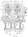
- FIG. 1 an internal combustion engine constructed in accordance with this embodiment of the invention is illustrated partially and is identified primarily by the reference numeral 1.
- the invention deals primarily with the induction system for the engine 1 and for that reason only the induction portion of the engine has been illustrated in detail along with certain adjacent components for orientation purposes.
- a cross-sectional view taken through a single cylinder of the engine 11 is all that is believed to be necessary to understand the construction and operation of the invention. It is believed obvious to those skilled in the art how the invention can be employed in conjunction with multiple cylinder engines of configuration.
- this embodiment could be seen as a part of a water-cooled four-cycle parallel four-cylinder four-valve engine having a structure in which a cylinder block 3 and a cylinder head 4 are stacked and joined with a forward inclination on the crank case 2 through head bolts, and the mating plane of the head cover side of the cylinder head 4 is covered with head covers 5.
- head covers 5 In each of the four cylinder bores 3a formed in the cylinder block 3 is slideably inserted at a piston 7 which is connected with a crank shaft (not shown) through a connecting rod 8.
- the cylinder head 4 has a lower surface 4a that is matingly engaged with the upper portion of the cylinder block 3 and cylinder bore 3a and which defines a combustion chamber in part by means of a combustion cavity 4b formed in the lower surface of the cylinder head 4.
- a combustion cavity 4b formed in the lower surface of the cylinder head 4.
- each a pair of intake valve openings 4c and exhaust valve openings 4d is disposed on each exhaust valve opening 4d.
- On each exhaust valve opening 4d is disposed a valve plate 10 a of an exhaust valve 10 and on each intake valve opening 4c is disposed a valve plate 11a of an intake valve 11 for opening/closing the valve openings 4d, 4c respectively.
- valve stems of the exhaust and intake valves 10 and 11 extend aslant upward generally in the direction of the cylinder axis under a definite angle therebetween as seen in the cam shaft direction and exhaust and intake lifters 12, 13 are mounted on the upper end of each of the valve stems 10b and 11 respectively.
- An exhaust cam shaft 14 and an intake cam shaft 15 extend respectively above each lifter 12, 13 in parallel to each other and perpendicularly to the axis of the cylinder bore, said lifters 12, 13 being driven by the cam shaft 14, 15.
- the two exhaust valve openings 4d are led out to the side of the front wall 4f of the cylinder head 4 through a biforcated exhaust passage 16 to the wall surface opening 16a to which an exhaust pipe (not shown) is connected.
- the two intake valve openings 4c are led out to the side of the rear wall 49 of the cylinder head 4 through a bifurcated intake passage 17 composed of a sub-passage 17g turning inside and a sub-passage 17h turning outside.
- these passages are also designated as primary and secondary intake passages or first and second sub-intake passages, formed in the cylinder head 4.
- each combustion chamber is served by such a pair of intake passages 17g, 17h while the present invention may also be employed in conjunction with engines having only a single intake passage for each combustion chamber or more than two intake passages for each combustion chamber.
- This intake passage 17 extends generally rectangularly to the cam shaft 15 as seen in the direction of the cylinder axis and extends generally straight after being bent obliquely from the intake valve opening 4c to the side of the rear wall 4g of the cylinder head, as seen in the direction of the camshaft.
- a manually operated main throttle valve 30 is positioned in a manifold 24 for controlling the speed of the operation of the engine 1 in a known manner.
- Said manifold 24 is in register with the intake passage 17 through a joint portion 18 which supports an auxiliary throttle valve 27 which is disposed at an opening 17a of the walls of the intake passage 17 extending transversely across the flow of air through the intake passages 17 and the manifold 24.
- An air cleaner 200 is disposed upstream of the manifold 24.
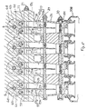
- valve bore 17c in the camshaft direction. That valve bore 17c is formed so as to have its axis positioned near the surface of a bottom wall 17d of the intake passage 17 and closely adjacent to the bight 17b between the stem 11b of the intake valve 11 and a cylinder head bolt at the intake side of the cylinder head 4, said valve bore 17c penetrating two adjacent intake passages 17, i.e. the first and second sub-intake passages 17h, 17g servicing a first cylinder and the first and second sub-intake passages 17g and 17h servicing the neighbouring cylinder as shown in Fig. 2.
- the valve bore 17c rotatably supports an intake air control valve 21 for varying the cross-section of the flow passage area of said intake passages 17 of the bifurcated type.
- a pair of left and right control valves 21 is disposed one by one at both sides of a cam chain (not shown) disposed at a centre portion of the engine.
- Each control valve 21 is formed of a round bar having four valve cutouts 21a and comprising a drive arm 21b fastened to an outer projecting end of the control valve 21. In a fully opened position of the control valve 21 the cutouts 21a form the bottom surface 17d of the wall and a corner of the side wall surface of the intake passage, i.e. of the bifurcated branch passages 17h, 17g. When the control valve 21 is rotated in its fully closed position, these cutouts 21a are effective to throttle the bottom wall side portion of the intake passage 17, leaving its ceiling wall side portion open.
- the air/fuel mixture of a charge to be burnt into the respective combustion chambers is formed by injecting fuel by a fuel injector 26 (fuel injection valve) injecting fuel respectively at the ceiling wall side of the first sub-intake passage 17h (turning outside) of the intake passage 17.
- the injection nozzle of the fuel injector 26 is directed from a fuel injection hole 26a (see Fig. 1) to an intake valve opening 4c of the sub-intake passage 17h for each cylinder of the engine.
- the invention is not restricted to a fuel injection type engine but, of course, a similar valve arrangement could also be applied to a carburettor type engine.
- an auxiliary valve 27 is disposed comprising a valve shaft 28 to which an auxiliary valve plate 29 is fastened through bolts for each of the intake passages 17.
- Said valve shaft 28 is rotatably supported through a valve support member in the camshaft direction and is driven by a drive arm 28b attached to an outwardly projecting end of the valve shaft 28.
- the auxiliary valve plate 29 is disposed such that a cutout 29a formed at a valve plate portion which is orientated to the outwardly turning sub-intake passage 17h respectively, into which fuel is discharged by the respective fuel injector 26. Therefore, when the auxiliary throttle valve 27, i.e. the auxiliary valve shaft 28, is rotated to its closed position, as shown in Fig. 3, only the second sub-intake passage 17g turning inside, to which the fuel injector 26 does not discharge, is closed.
- the main throttle valve 30 has a structure in which a pair of throttle valve plates 30a is fastened through bolts on a throttle valve shaft 30c extending transversely through the manifold side induction passage 24 in the camshaft direction and the throttle valve shaft 30c is driven through a drive arm 30b secured to its outwardly projecting end. That drive arm 30b is connected to a throttle grip 25 through a drive cable 25a (Fig. 1).
- a valve operating control system 31 comprising a CPU 31a and drive motors (Stepper motors) 31b, 31c connected to the drive arms 28b and 21b of the auxiliary throttle valve 27 and control valve 21 respectively.
- the CPU 31a receives an input indicative of engine speed as provided by an engine speed sensor that cooperates the engine crank shaft as known and an input indicative of the position of the main throttle valve 30.
- the Stepper motor 31c is connected by means of a connection B to the drive arm 21b whereas the Stepor motor 31b is connected by means of a connection A to the drive arm 28b that is connected to the auxiliary valve shaft 28.
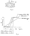
- Fig. 4 shows the relation of the valves 27, 21 and 30 between their fully closed position 0% and their fully opened position 100% in relation to engine speed. Also shown are the respective swirl and tumble conditions.
- the main throttle valve 30 is opened in linear fashion and during initial opening of the main throttle valve 30, the control valve 21 and, in this embodiment, also the auxiliary throttle valve 27 are maintained closed.
- the intake air is blown into the combustion chamber with high speed only through the sub-intake passage 17h respectively left open, in a one-sided manner along its ceiling wall, producing swirls flowing from the sub-intake passage side 17h to the opposite side and further produces tumble flowing downward from the ceiling wall side.
- the swirl effect will be reduced while tumble will be kept strong yet.
- the auxiliary throttle valve 27 begins to open and then the intake air control valve 21 begins to open.
- the tumble will then be weakened and a period where weak tumble and weak swirl are both maintained will occur up through the mid-range performance until all valves are opened, at which time there will be substantially no tumble or swirl. This may provide excellent performance throughout the entire range of engine speed and engine load.
- both swirl and tumble can be simultaneously produced in a condition of a low amount of intake air. Therefore, lean mixture combustion can be stabilised by promoting fuel atomisation and uniformisation of the distribution of the air/fuel mixture can be improved, leading to a correspondingly improved lower fuel consumption.
- Fig. 5 shows yet another alternative embodiment of the invention which differs from the afore-described embodiment of Figs. 1 to 4 only in the fact that the auxiliary throttle valve 27 in this embodiment has only a single valve plate 29 which cooperates to control the flow through the sub-intake passage 17g.
- the auxiliary throttle valve 27 was shifted to a more downward position, i.e. to the bifurcated area of the intake passage 17. In this way the restriction of flow through the sub-intake passage 17h is very low under all conditions and hence even better volumetric efficiency can be achieved.
- FIG. 6 to 10 Another embodiment of the present invention is explained hereinafter referring to Figs. 6 to 10. Substantially the engine and its basic construction complies with that above-described above with respect to Figs. 1 to 4 and, therefore, a repetitious explanation of said basic structure of the engine is not considered to be necessary and is, therefore, omitted. Like parts as in the above-mentioned first embodiment are denoted with the same reference numerals also in the embodiment hereinafter described with reference to Figs. 6 to 10.
- the induction system includes a charge former 19 in the form of a variable venturi carburettor which draws atmospheric air from an air cleaner (not shown).
- the carburettor 19 is formed with an intake passage 24 in which a sliding throttle piston 19b is automatically operated through the intake vacuum of the engine, said throttle piston 19b being supported for reciprocation.
- the piston 19b is operated to maintain a constant pressure drop through the intake passage 24 regardless of the running speed of the engine.
- a metering rod 19a is affixed to the throttle piston 19b for controlling the supply of fuel delivered to the manifold induction passage 24 by the idle and main circuits (not shown) of the carburettor 19.
- the manually operated main throttle valve 30 is positioned in the carburettor intake passage 24 for controlling the speed of operation of the engine 1 in a known manner.
- the carburettor 19 is of the type normally used in a motor cycle and the engine 1 in this embodiment may be employed to drive a motor cycle.
- the invention may be practised in conjunction with other applications for internal combustion engines. This embodiment, however, has particular utility in conjunction with engines that operate over widely varying speed and load ranges.
- the carburettor 19 supplies its air/fuel charge to a short Siamese type intake manifold 18 that has a single inlet opening that registers with the carburettor intake passage 24 and a pair of outward openings which respectively communicate with the inlet openings of the pair of intake passages 17g, 17h formed in the cylinder head 4.
- each combustion chamber is served by the pair of intake passages 17h, 17g with the intake passage 17h being considered as the primary or first sub-intake passage and the intake passage 17g being considered as the secondary sub-intake passage.
- this embodiment can be employed in conjunction with engines having only a single intake passage for each combustion chamber or more than than two intake passages for each combustion chamber.
- each of the intake passages 17h, 17g has a generally L-shaped configuration with a straight section running from the inlet openings that communicate with the manifold 18 and a shorter section that is angularly disposed to the first section and which communicates directly with the combustion chamber 4b. These sections meet at a bight at which again the control valve 21 is rotatably supported.
- This embodiment is to further enhance generating a tumble and/or swirl action in the combustion chamber 4b under low and mid range operations.
- the flow path of the intake charge entering the combustion chamber 4b from the intake passages 17h, 17g is varied under certain running conditions so as to induce turbulence, improving flame propogation and to ensure complete combustion within the combustion chamber 4b, even under extreme idle and low speed conditions.
- a rectifier plate arrangement 20 is positioned in the primary intake passage 17h.
- the intake air control valve 21 can be rotated between its fully opened position, at which the valve portion 21a is immersed in the valve bore 17c to be flush with the inner surface of the corresponding intake passage, and its fully closed position, at which the valve cutout 21a is erected from the bottom wall 17d nearly perpendicular to throttle the intake passage 17 nearly to one-half.
- the control valve 21 rotates so that the outer periphery of the cutouts 21a may be positioned on the upstream side.
- the auxiliary throttle valve 27 In the intake manifold 18 is disposed the auxiliary throttle valve 27, the valve shaft 28 of which extends in parallel to the control valve 21 and supports a valve plate 29 to open or close the secondary intake passage 17g.
- control pulley 22a which is connected to the drive pulley 22b secured to a control motor through a cable.
- a changeover pulley 27c which is connected to the drive pulley 27d secured on a changeover motor through a cable.
- the rotations of the control motors are controlled by an ECU 23 which again receives a main throttle opening representing signal of the main throttle valve 30 from a throttle opening sensor 25a and the engine speed representing signal from the rotation sensor 25b.
- the ECU 23 outputs a control signal A to the control motor for rotating the control valve 21 towards its fully closed position as the amount of intake air becomes smaller as is the case within the low to medium speed/low to medium load engine operating ranges or toward its fully open position as the amount of intake air becomes larger as is the case within the high speed/high load engine operating range.
- the CPU outputs another control signal B to the changeover motor indicated above to close the auxiliary throttle valve 27 in the engine operating range where the amount of intake air is smaller than a specified value or to open the auxiliary throttle valve 27 in an engine operating range where the amount of intake air exceeds the specified value mentioned above.
- a partitioning rectifer plate arrangement 20 is provided in the intake passage 17h to which the valve plate 29 of the auxiliary throttle valve 27 is not orientated and said partition plate or rectifier plate arrangement 20 is disposed downstream of the intake air control valve 21.
- the partition plate arrangement 20 is composed of a tongue-like partition plate portion 20a and a cylindrical base portion 20b which forms an angular holder ring and is secured on the downstream end portion of the partition plate portion 20a. Said cylindrical base portion 20b is caught and held at its holder ring portion by a valve seat of an intake valve 11, fitted and mounted in the intake valve opening 4c.
- the reference numeral 20c denotes a groove formed for avoiding any interference between the partition plate 20 and the valve stem 11a of the intake valve 11.
- the partition plate portion 20a extends generally along a centre line of the intake passage 17h and has a width nearly equal to that of the intake passage 17h to divide it into two portions, one on each side of the axis of the intake valve 11.
- the flow controlling position of the control valve 21 is such that there is no cavity formed in the intake passage upstream of the control valve 21 when in its flow controlling position in which fuel could tend to condense and accummulate.
- the cutout 21a of the control valve 21 forms a continuous surface with the rectifier plate portion 20a.
- the partition plate portion 20a divides the intake passage 17h into the ceiling wall side portion C and the bottom wall side portion D.
- the ECU 23 positions the auxiliary throttle valve 27 in its closed position and the control valve 21 in its flow controlling position when the engine is operating at idle or off idle. This induces maximum turbulence in the combustion chamber and a helical flow pattern so as to ensure rapid flame propagation when the spark plug 9 is fired and so as to also ensure that a stoichiometric fuel/air mixture will be present at the gap of the spark plug 9 at the time of ignition.
- the intake air is concentrated into the remaining intake passage 17h and only flows into the cylinder through the upper side intake valve opening 4c of Figure 9. Moreover, it only flows through the sealing wallside portion C of the passage 17h divided by the rectifier plate arrangement 20.
- a direction of the flow of intake air can be obtained even when the amount of intake air is small and a helical flow pattern is produced in which the intake air flows along the cylinder inner surface laterally as seen in the direction of the cylinder axis and flows longitudinally along the axis of the cylinder as seen in the camshaft direction.
- auxiliary throttle valve 27 is first opened while the control valve 21 is still maintained in its flow controlling position. This changes the motion within the combustion chamber 4b from the helical flow pattern to a tumble type of flow pattern. Then, as the speed and load further increase, the control valve 21 is positioned in its open position so as to permit unresricted flow into the combustion chamber 4b and maximum volumetric efficiency. As has been noted, this is only a preferred sequence of operation and whereas other sequences of operation may be employed depending upon the type of motion desired in the combustion chamber 4b under various running conditions.
- the rectifier plate portion 20a had the effect of dividing the primary intake passage 17h into two substantially equal flow areas.
- Figures 11-13 show another embodiment of the invention wherein the configuration of the rectifier plate arrangement is such as to provide a substantially smaller flow area than one-half through the intake passage 17h when the control valve 21 is in its closed position.
- the partitioning plate portion 20c of the rectifier plate arrangement 20 extends outwardly from the cylindrical base portion 20b and has a generally V-shaped configuration terminating a generally flat upstream portion 20a which forms a plane generally continued from the cut out 21a of the intake air control valve 21, said upstream and forming also a stopper for limiting the movement of the cut out 21a of the control valve 21 into its flow controlling position.
- the V-shape of the plate portion 30c defines a relatively small flow area which is directed more towards the centre of the cylinder and which will generate a higher flow velocity and more tubulence then created in the previously described embodiment.
- such a rectifier plate can be positioned in only one of a plurality of intake passage serving the same cylinder or, alternatively, may be provided in all of the intake passages serving the same cylinder.
- such a configuration may be employed in engines having only one intake passage per cylinder.
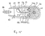
- FIGS 14 and 15 illustrate another embodiment which is generally the same as the previously described ones and, for that reason, components of this embodiment which are the same or substantially the same have been identified by the same reference numerals and will not be described again, except in so far as is necessary to understand the construction and operation of this embodiment.
- the engine is designed primarily for automotive application.
- the engine 1 is provided with an induction system comprising a plenum chamber 29.
- the intake passage is bifurcated into the intake passages 17h and 17g and the auxiliary throttle valve 27 for opening/closing the lower side of the intake passage 17h is disposed at their joining portion.
- a fuel/air charge is generated by the fuel injector 26 which is mounted to each manifold runner 18 and which sprays fuel therein under an appropriate control strategy.
- auxiliary throttle valve 27 had a shaft portion 28 extended through the primary intake passage 17h and, thus, provided some, although minimal, flow resistance in this passage.
- the advantage of the construction of the previously described embodiments was that all of the auxiliary throttle valves 27 could be fixed to a common throttle valve shaft 28.
- the auxiliary throttle valve arrangement 27 is provided for each cylinder of the engine separately.
- This auxiliary throttle valve 27 has a structure in which its valve plate 29 is secured on one end of its shaft portion 28 which is inserted into the intake passge 17h from above and is rotatable about a vertical axis.
- valve plate 29 when in its closed position, substantially precludes any flow through the secondary intake passage 17g and, hence, will divert all of the flow through the primary intake passage 17h with the effect as afore-mentioned.
- the valve plate 29 When the auxiliary throttle valve 27 is rotated the valve plate 29 will extend parallel to the flow path and provide only minimal resistance.
- Each of the throttle valves 27 is provided with an outwardly extending arm which allows all auxiliary throttle valves 27 of the engine to be interconnected to each other as to provide simultaneous movement therebetween.
- this embodiment means that the engine has three steps of different intake flow patterns beyond the full range of engine speed. Namely, the first stage is acquired when the valve plate 29 assumes its closed position and control valve 21 also assumes its closed position, whereas the second stage is obtained when the valve plate 29 assumes its closed position and the control valve 21 assumes its open position while finally, the third stage is characterized in that all valves including the valve plate 29 and the control valve 21 assumes its open position.
- the fuel injection valve 26 may be set so as to inject fuel nearly toward the space between the rectifier plate arrangement 20 and the sealing wall of the associated intake passage 17h.
- the method for directing the intake flow of air is not limited to that disposal of the auxiliary throttle valve 27 as described above.
- similar concentration of the air flow can be realised by stopping the operation of one intake valve at its closed state.
- the rectifier plate arrangement 20 is disposed in the intake passage on the side where the operation of the intake valve is not stopped.
Description
- This invention relates to an induction system for an internal combustion engine having a cylinder head and a cylinder block, said cylinder head at least partially defining a combustion chamber, and an intake passage arrangement for each cylinder to serve a plurality of intake valves, with a main throttle valve arrangement being provided at an upstream side of the intake passage arrangement.
- As is well known, most internal combustion engines are called upon, in their application, to operate over widely varying speed and load ranges. This is particularly true in connection with vehicular applications such as automobiles and motorcycles. As is also well known, because of this speed and load variation over which the engine is operated, there are many compromises in the design of the engine. This is particularly true in the area of the induction system.
- It has been well known that combustion at low engine speeds and low engine loads can be significantly improved with attendant improvements in fuel economy and exhaust emission control if a high degree of turbulence is induced into the intake charge and in the combustion chamber. However, all turbulence increasing devices in the induction system tend to offer some flow resistance. Therefore, the use of turbulence increasing devices in the induction system reduces the maximum power output of the engine. Thus, most induction systems are designed as compromise between good low speed performance and good high speed performance.
- One form of turbulence which is generated in the combustion chamber is characterized as "swirl". Swirl is a flow of the charge in the combustion chamber in a generally circumferential direction around the axis of the cylinder. Swirl is generally generated by use of swirl ports in the induction system. However, the generation of swirl can reduce the volumetric efficiency at high speed. This is because swirl ports have higher flow resistance than non-swirl ports. In addition, there are some phases of running of the engine when swirl is not desirable even though some form of motion of the charge in the chamber is desirable.
- Another form of motion in the combustion chamber is called "tumble". Tumble is a swirling motion of the intake charge about an axis that generally extends transversely to the cylinder bore axis. With such a flow arrangement, the charge tends to flow across the cylinder head, down one side of the cylinder bore, back across the cylinder bore across the top of the head of the piston and then up the other side of the cylinder bore back to the cylinder head with this flow pattern repeating. This type of motion also requires the formation of a specially formed port which will provide flow resistance and reduce volumetric efficiency under high speed. Like swirl, tumble is more effective at some speed than other speeds.
- Of course, even more turbulence may be generated in the intake charge if both swirl and tumble can be generated at the same time. However, generating both such motions through a single port configuration can further increase the flow resistance and reduce high speed performance.
- One way in which the flow pattern in the combustion chamber can be varied under varying speed and load conditions is to provide a control valve in the induction passage that changes the effective configuration of the induction passage as the control valve is moved. The control valve can then be moved in response to varying speed and load conditions so as to provide the desired flow pattern. Such arrangements, however, as previously proposed have only permitted the establishment of either one type of swirling motion (either swirl or tumble) or substantially no turbulence.
- One technique for changing the flow pattern from an intake passage in an internal combustion engine employs an additional passage that intersects the main intake passage upstream of the valve seat and through which another higher velocity flow is established. However, like other flow altering devices, there are some running conditions when it is not desirable to have this small port be effective. This can be done through the provision of a control valve but if another control valve is also employed for changing the effective configuration of the port, then the engine becomes very complicated. Furthermore, it may be physically impossible to employ two such valves in the cylinder head of an engine, where the intake port is normally formed.
- As has been noted, one way in which the flow patten within a combustion chamber may he altered is by providing a control valve that operates in the intake passage of the engine. However, where such a control valve is provided, even when the control valve is in a wide open position, some obstruction to the flow through the intake passage may occur. This can be either by direct flow resistance of the valve or a mounting portion of it extending into the induction passage even when the valve is fully opened. In addition, the control valve in its fully open position or some portion associated with it can give rise to a less than smooth intake passage which will induce turbulence within the intake passage itself and, accordingly, adversely effect volumetric efficiency.
- US 4 317 438 shows an induction system of the above-mentioned type. This induction system is, however, unsatisfactory, as it has the above-mentioned drawbacks such as an unwanted flow resistance for some running conditions.
- Moreover, in addition to providing swirl and tumble actions simultaneously it is desirable to improve the engine fuel consumption in the ranges of low to medium engine speed or engine load. In this way also a lean mixture combustion could be stabilised by improving the fuel atomisation and uniformised mixture distribution in order to improve the fuel consumption of the engine.
- Accordingly, it is an objective of the present invention to provide an improved induction system for an internal combustion engine which permits the generation of swirl and or tumble depending on the running conditions of the engine allowing not only to selectively increase the turbulence of the charge in the combustion chamber under some running conditions while adjusting different flow patterns under other running conditions but should also improve stabilised lean mixture combustion in the low engine performance range.
- According to the present invention, the above-mentioned objective is performed in that the intake passage arrangement is controlled by an intake air control valve for varying the cross section of the flow passage area of said intake passage arrangement, which is rotatably supported at the lower side of the intake passage arrangement in the cylinder head, the engine being considered in an upright position with the cylinder head at the top of it, the axis of the control valve extends transversely to the flow path of an intake charge flowing through the intake passage arrangement and in the direction of the axis of an overhead camshaft, said control valve being disposed at least in the vicinity of an end portion of the intake passage close to the combustion chamber, and in that, an auxiliary throttle valve is disposed between the main throttle valve and the control valve to control at least a part of the cross section of the intake passage arrangement, said auxiliary throttle valve being designed to prevent an obstruction of at least a part of the cross section of the intake passage irrespective of the angular position of the auxiliary throttle valve, but to obstruct the flow through a remainder part of the cross section of the intake passage in a fully closed position of the auxiliary throttle valve.
- The induction system according to the present invention has the advantageous effect that, while the intake air amount is small, as is for example the case during the low to medium speed engine operating range, the auxiliary throttle valve partly closes the intake passage or primary and secondary sub-intake passages of a Siamese type intake passage arrangement, leaving only the remaining intake passage or sub-intake passage open and the intake air control valve is rotated to its closed position and throttles that intake passage or sub-intake passage on the bottom valve side of the flow passage which was left open by the auxiliary throttle valve. Under such a condition, the intake air flows along one side through the intake passage or one of the primary or secondary sub-intake passages on the side left open by the auxiliary throttle valve and in a one-sided orientation along the ceiling wall side of the intake passage. Consequently, the intake air will be blown into the combustion chamber producing horizontal swirl flowing from the intake valve opening on that side left open through the auxiliary throttle valve towards the upper side and, moreover, producing tumble action flowing downward from the ceiling wall side. Therefore, tumble and swirl is produced simultaneously and the atomisation of fuel as well as the uniformisation of the distribution of the air/fuel mixture are promoted.
- According to a preferred embodiment of the present invention, a valve operating control system is provided to operate said control valve, which, most preferably, is disposed at a bight of the respective intake passage or at least one of primary or secondary sub-intake passages, and said valve operating control system is similarly provided to operate the auxiliary throttle valve, both of said control and auxiliary throttle valves are operated in response to engine running conditions such as to close said valves in the range of low to medium engine speed or engine load.
- According to another preferred embodiment of the present invention the control valve comprises a plate-shaped valve body having control cutouts for controlling a plurality of sub-intake passages of a single cylinder of the engine.
- In order to avoid that some vacancy which is generated on the downstream side of the control valve causing flow disturbances during low speed operation it is preferred that a rectifier plate arrangement (partition plate) is provided for dividing the portion of the intake passage downstream of the intake air control valve into a ceiling wall side portion and a bottom wall side portion. Said partition plate or rectifier plate arrangement has a plate portion which establishes a stop for the control valve rotated to its fully closed position. Within the framework of this arrangement it is also possible that the plate portion of the rectifier plate arrangement partitioning the intake passage is to make nearly contact with the control valve rotated to its fully closed position.
- Other preferred embodiments of the present invention are laid down in the further sub-claims.
- The latter-mentioned embodiments, namely the provision of a partition plate or rectifier plate arrangement downstream of the control valve which preferably is disposed at a bight of the associated portion of the intake passage close to a combustion chamber, further improves the tumble action of the charge in the combustion chamber as said area of the intake passage can be adjusted to show a small cross-section of the passage area thus increasing the speed of the charge introducing the intake air into the cylinder in a vertical direction and enabling the mixture to be combusted stablised. Moreover, said system allows a wide variability of adjusting the amount and distribution of the intake charge to meet specifically low load engine running conditions.
- In the following the present invention is explained in greater detail by means of several embodiments in conjunction with the accompanying drawings:
- Fig. 1 is an end elevational view of an internal combustion engine constructed in accordance with an embodiment of the present invention with portions broken away and showing a cross-section and certain portions of the engine eliminated and certain of its components shown schematically, representing a cross-section along the lines II-II in Fig. 2,
- Fig. 2 is a sectional plane view showing an intake air control system according to Fig. 1,
- Fig. 3 is a sectional view taken along the line III-III of Fig. 2,
- Fig. 4 is a graphical view showing how the various valves are operated in conjunction with this embodiment in relation to valve opening and engine speed,
- Fig. 5 is a sectional end view showing a modification of the arrangement and disposition of the auxiliary throttle valve, in part similar to Fig. 2,
- Fig. 6 is an end elevational view of an internal combustion engine constructed in accordance with another embodiment of the present invention with portions broken away and showing cross-section and certain portions of the engine eliminated and certain of its controls shown sechematically, similar to Fig. 1,
- Fig. 7 is a further enlarged view of the combustion chamber area of the engine and an intake valve taken along the same plane as of Fig. 1,
- Fig. 8 is a cross-sectional view taken along the line III-III of Fig. 7,
- Fig. 9 is an enlarged cross-sectional view taken along the line IV-IV of Fig. 6,
- Fig. 10 is an enlarged perspective view showing a cooperation of the control valve with the rectifier plate arrangement,
- Fig. 11 is a cross-sectional view, in part similar to Fig. 7, showing another embodiment of the present invention,
- Fig. 12 is a cross-sectional view taken along the line VII-VII of Fig. 11,
- Fig. 13 is a perspective view, in part similar to Fig. 10, showing the cooperation of the control valve with the rectifier plate of said embodiment,
- Fig. 14 is a side elevational view of an internal combustion engine constructed in accordance with another embodiment of the present invention with a portion broken away, and
- Fig. 15 is a cross-sectional view taken along the line IX-IX of Fig. 14.
- Referring first to the embodiment of Figs. 1 to 4 and initially primarily to Fig. 1, an internal combustion engine constructed in accordance with this embodiment of the invention is illustrated partially and is identified primarily by the reference numeral 1. The invention deals primarily with the induction system for the engine 1 and for that reason only the induction portion of the engine has been illustrated in detail along with certain adjacent components for orientation purposes. In addition, a cross-sectional view taken through a single cylinder of the
engine 11 is all that is believed to be necessary to understand the construction and operation of the invention. It is believed obvious to those skilled in the art how the invention can be employed in conjunction with multiple cylinder engines of configuration. Accordingly, this embodiment could be seen as a part of a water-cooled four-cycle parallel four-cylinder four-valve engine having a structure in which acylinder block 3 and acylinder head 4 are stacked and joined with a forward inclination on the crankcase 2 through head bolts, and the mating plane of the head cover side of thecylinder head 4 is covered with head covers 5. In each of the fourcylinder bores 3a formed in thecylinder block 3 is slideably inserted at apiston 7 which is connected with a crank shaft (not shown) through a connectingrod 8. Thecylinder head 4 has alower surface 4a that is matingly engaged with the upper portion of thecylinder block 3 and cylinder bore 3a and which defines a combustion chamber in part by means of acombustion cavity 4b formed in the lower surface of thecylinder head 4. At the centre of thecombustion cavity 4b is screwed in anignition plug 9 and around thisignition plug 9 is disposed each a pair ofintake valve openings 4c andexhaust valve openings 4d. On eachexhaust valve opening 4d is disposed avalve plate 10 a of anexhaust valve 10 and on each intake valve opening 4c is disposed avalve plate 11a of anintake valve 11 for opening/closing thevalve openings intake valves intake lifters exhaust cam shaft 14 and anintake cam shaft 15 extend respectively above eachlifter lifters cam shaft - The two
exhaust valve openings 4d are led out to the side of the front wall 4f of thecylinder head 4 through abiforcated exhaust passage 16 to the wall surface opening 16a to which an exhaust pipe (not shown) is connected. The twointake valve openings 4c are led out to the side of therear wall 49 of thecylinder head 4 through abifurcated intake passage 17 composed of a sub-passage 17g turning inside and a sub-passage 17h turning outside. Within the framework of this application these passages are also designated as primary and secondary intake passages or first and second sub-intake passages, formed in thecylinder head 4. It is to be understood that in this embodiment each combustion chamber is served by such a pair ofintake passages intake passage 17 extends generally rectangularly to thecam shaft 15 as seen in the direction of the cylinder axis and extends generally straight after being bent obliquely from the intake valve opening 4c to the side of the rear wall 4g of the cylinder head, as seen in the direction of the camshaft. - A manually operated
main throttle valve 30 is positioned in a manifold 24 for controlling the speed of the operation of the engine 1 in a known manner. Saidmanifold 24 is in register with theintake passage 17 through ajoint portion 18 which supports anauxiliary throttle valve 27 which is disposed at anopening 17a of the walls of theintake passage 17 extending transversely across the flow of air through theintake passages 17 and the manifold 24. Anair cleaner 200 is disposed upstream of the manifold 24. - At a
bight 17b of theintake passage 17 bent arcutely extends avalve bore 17c in the camshaft direction. That valve bore 17c is formed so as to have its axis positioned near the surface of abottom wall 17d of theintake passage 17 and closely adjacent to the bight 17b between thestem 11b of theintake valve 11 and a cylinder head bolt at the intake side of thecylinder head 4, said valve bore 17c penetrating twoadjacent intake passages 17, i.e. the first and secondsub-intake passages sub-intake passages air control valve 21 for varying the cross-section of the flow passage area of saidintake passages 17 of the bifurcated type. A pair of left andright control valves 21 is disposed one by one at both sides of a cam chain (not shown) disposed at a centre portion of the engine. Eachcontrol valve 21 is formed of a round bar having fourvalve cutouts 21a and comprising adrive arm 21b fastened to an outer projecting end of thecontrol valve 21. In a fully opened position of thecontrol valve 21 thecutouts 21a form thebottom surface 17d of the wall and a corner of the side wall surface of the intake passage, i.e. of thebifurcated branch passages control valve 21 is rotated in its fully closed position, thesecutouts 21a are effective to throttle the bottom wall side portion of theintake passage 17, leaving its ceiling wall side portion open. - In this embodiment the air/fuel mixture of a charge to be burnt into the respective combustion chambers is formed by injecting fuel by a fuel injector 26 (fuel injection valve) injecting fuel respectively at the ceiling wall side of the first
sub-intake passage 17h (turning outside) of theintake passage 17. The injection nozzle of thefuel injector 26 is directed from afuel injection hole 26a (see Fig. 1) to an intake valve opening 4c of thesub-intake passage 17h for each cylinder of the engine. As is apparent also from other embodiments of the present invention explained below, the invention is not restricted to a fuel injection type engine but, of course, a similar valve arrangement could also be applied to a carburettor type engine. Downstream of themain throttle valve 30 but upstream of thecontrol valve 21 and the fuel injection into the respectivesub-intake passage 17h anauxiliary valve 27 is disposed comprising avalve shaft 28 to which anauxiliary valve plate 29 is fastened through bolts for each of theintake passages 17. Saidvalve shaft 28 is rotatably supported through a valve support member in the camshaft direction and is driven by adrive arm 28b attached to an outwardly projecting end of thevalve shaft 28. As shown in Figs. 2 and 3 theauxiliary valve plate 29 is disposed such that acutout 29a formed at a valve plate portion which is orientated to the outwardly turningsub-intake passage 17h respectively, into which fuel is discharged by therespective fuel injector 26. Therefore, when theauxiliary throttle valve 27, i.e. theauxiliary valve shaft 28, is rotated to its closed position, as shown in Fig. 3, only the secondsub-intake passage 17g turning inside, to which thefuel injector 26 does not discharge, is closed. - The
main throttle valve 30 has a structure in which a pair ofthrottle valve plates 30a is fastened through bolts on athrottle valve shaft 30c extending transversely through the manifoldside induction passage 24 in the camshaft direction and thethrottle valve shaft 30c is driven through adrive arm 30b secured to its outwardly projecting end. Thatdrive arm 30b is connected to athrottle grip 25 through adrive cable 25a (Fig. 1). - In order to control the
control valve 21 and the auxiliary throttle valve 27 a valveoperating control system 31 is provided comprising aCPU 31a and drive motors (Stepper motors) 31b, 31c connected to thedrive arms auxiliary throttle valve 27 andcontrol valve 21 respectively. TheCPU 31a receives an input indicative of engine speed as provided by an engine speed sensor that cooperates the engine crank shaft as known and an input indicative of the position of themain throttle valve 30. The Stepper motor 31c is connected by means of a connection B to thedrive arm 21b whereas theStepor motor 31b is connected by means of a connection A to thedrive arm 28b that is connected to theauxiliary valve shaft 28. The sequence of cooperation of opening and closing the respectiveauxiliary throttle valve 27 andcontrol valve 21 may be understood by reference to Fig. 4. TheCPU 31a provides the control signals to theStepper motors 31b, 31c such that thevalves valves closed position 0% and their fully openedposition 100% in relation to engine speed. Also shown are the respective swirl and tumble conditions. As may be seen, themain throttle valve 30 is opened in linear fashion and during initial opening of themain throttle valve 30, thecontrol valve 21 and, in this embodiment, also theauxiliary throttle valve 27 are maintained closed. While bothvalves auxiliary throttle valve 27 begins to open. As theauxiliary throttle valve 27 begins to open, the swirl effect will be reduced while tumble will still be maintained strong. Thus, when the engine speed is in the low speed range or when the engine is operating in the low load operating range where the throttle opening is small and theauxiliary throttle valve 27 and thecontrol valve 21 are rotated to their fully closed positions, theauxiliary throttle valve 27 only closes thesub-intake passage 17g and thecontrol valve 21 throttles eachintake passage bottom wall side 17d leaving the ceiling wall side portion open. Consequently, the intake air is blown into the combustion chamber with high speed only through thesub-intake passage 17h respectively left open, in a one-sided manner along its ceiling wall, producing swirls flowing from thesub-intake passage side 17h to the opposite side and further produces tumble flowing downward from the ceiling wall side. As afore-mentioned with the opening of theauxiliary throttle valve 27 the swirl effect will be reduced while tumble will be kept strong yet. - When the engine speed increases further and comes into the medium speed range, or when the engine is operating in the medium low range where the throttle opening is medium, at first the
auxiliary throttle valve 27 begins to open and then the intakeair control valve 21 begins to open. Thus, when a position is reached before theauxiliary throttle valve 27 is fully opened and thecontrol valve 21 has begun to open the tumble will then be weakened and a period where weak tumble and weak swirl are both maintained will occur up through the mid-range performance until all valves are opened, at which time there will be substantially no tumble or swirl. This may provide excellent performance throughout the entire range of engine speed and engine load. In the course of opening theauxiliary throttle valve 27 and, decelerated thereagainst, thecontrol valve 21, the intake air flow into thesub-intake passage 17g gradually increases and the flow along the ceiling wall of thesub-intake passage 17h becomes weaker. Therefore, swirl becomes weaker first and then tumble also becomes weaker until said effects substantially will disappear as afore-mentioned (high speed operating range, high load operating range). - According to this embodiment, as the
auxiliary throttle valve 27 closes the secondsub-intake passage 17g (turning inside) leaving the firstsub-intake passage 17h open (turning outside) while thecontrol valve 21 throttles the intake passage from the bottom wall side 13d leaving the ceiling wall side portion open in the low speed operating range (or low load operating range) as described above, both swirl and tumble can be simultaneously produced in a condition of a low amount of intake air. Therefore, lean mixture combustion can be stabilised by promoting fuel atomisation and uniformisation of the distribution of the air/fuel mixture can be improved, leading to a correspondingly improved lower fuel consumption. - Fig. 5 shows yet another alternative embodiment of the invention which differs from the afore-described embodiment of Figs. 1 to 4 only in the fact that the
auxiliary throttle valve 27 in this embodiment has only asingle valve plate 29 which cooperates to control the flow through thesub-intake passage 17g. Thus, in this case, theauxiliary throttle valve 27 was shifted to a more downward position, i.e. to the bifurcated area of theintake passage 17. In this way the restriction of flow through thesub-intake passage 17h is very low under all conditions and hence even better volumetric efficiency can be achieved. - Another embodiment of the present invention is explained hereinafter referring to Figs. 6 to 10. Substantially the engine and its basic construction complies with that above-described above with respect to Figs. 1 to 4 and, therefore, a repetitious explanation of said basic structure of the engine is not considered to be necessary and is, therefore, omitted. Like parts as in the above-mentioned first embodiment are denoted with the same reference numerals also in the embodiment hereinafter described with reference to Figs. 6 to 10.
- In this embodiment the induction system includes a charge former 19 in the form of a variable venturi carburettor which draws atmospheric air from an air cleaner (not shown). The
carburettor 19 is formed with anintake passage 24 in which a slidingthrottle piston 19b is automatically operated through the intake vacuum of the engine, saidthrottle piston 19b being supported for reciprocation. Thepiston 19b is operated to maintain a constant pressure drop through theintake passage 24 regardless of the running speed of the engine. In addition a metering rod 19a is affixed to thethrottle piston 19b for controlling the supply of fuel delivered to themanifold induction passage 24 by the idle and main circuits (not shown) of thecarburettor 19. The manually operatedmain throttle valve 30 is positioned in thecarburettor intake passage 24 for controlling the speed of operation of the engine 1 in a known manner. Thecarburettor 19 is of the type normally used in a motor cycle and the engine 1 in this embodiment may be employed to drive a motor cycle. Of course, the invention may be practised in conjunction with other applications for internal combustion engines. This embodiment, however, has particular utility in conjunction with engines that operate over widely varying speed and load ranges. - The
carburettor 19 supplies its air/fuel charge to a short Siamesetype intake manifold 18 that has a single inlet opening that registers with thecarburettor intake passage 24 and a pair of outward openings which respectively communicate with the inlet openings of the pair ofintake passages cylinder head 4. In this embodiment each combustion chamber is served by the pair ofintake passages intake passage 17h being considered as the primary or first sub-intake passage and theintake passage 17g being considered as the secondary sub-intake passage. As noted above, also this embodiment can be employed in conjunction with engines having only a single intake passage for each combustion chamber or more than than two intake passages for each combustion chamber. Again each of theintake passages combustion chamber 4b. These sections meet at a bight at which again thecontrol valve 21 is rotatably supported. - This embodiment is to further enhance generating a tumble and/or swirl action in the
combustion chamber 4b under low and mid range operations. The flow path of the intake charge entering thecombustion chamber 4b from theintake passages combustion chamber 4b, even under extreme idle and low speed conditions. For this reason, in addition to the provision of thecontrol valve 21 and theauxiliary throttle valve 27, arectifier plate arrangement 20 is positioned in theprimary intake passage 17h. The intakeair control valve 21 can be rotated between its fully opened position, at which thevalve portion 21a is immersed in the valve bore 17c to be flush with the inner surface of the corresponding intake passage, and its fully closed position, at which thevalve cutout 21a is erected from thebottom wall 17d nearly perpendicular to throttle theintake passage 17 nearly to one-half. In this case thecontrol valve 21 rotates so that the outer periphery of thecutouts 21a may be positioned on the upstream side. In theintake manifold 18 is disposed theauxiliary throttle valve 27, thevalve shaft 28 of which extends in parallel to thecontrol valve 21 and supports avalve plate 29 to open or close thesecondary intake passage 17g. - At the outer end portion of the
control valve 21 is secured acontrol pulley 22a which is connected to the drivepulley 22b secured to a control motor through a cable. To the outer end portion of theauxiliary throttle valve 27 is secured a changeover pulley 27c which is connected to the drive pulley 27d secured on a changeover motor through a cable. The rotations of the control motors are controlled by anECU 23 which again receives a main throttle opening representing signal of themain throttle valve 30 from athrottle opening sensor 25a and the engine speed representing signal from the rotation sensor 25b. TheECU 23 outputs a control signal A to the control motor for rotating thecontrol valve 21 towards its fully closed position as the amount of intake air becomes smaller as is the case within the low to medium speed/low to medium load engine operating ranges or toward its fully open position as the amount of intake air becomes larger as is the case within the high speed/high load engine operating range. Moreover, the CPU outputs another control signal B to the changeover motor indicated above to close theauxiliary throttle valve 27 in the engine operating range where the amount of intake air is smaller than a specified value or to open theauxiliary throttle valve 27 in an engine operating range where the amount of intake air exceeds the specified value mentioned above. In order to further improve tumble motion a partitioningrectifer plate arrangement 20 is provided in theintake passage 17h to which thevalve plate 29 of theauxiliary throttle valve 27 is not orientated and said partition plate orrectifier plate arrangement 20 is disposed downstream of the intakeair control valve 21. Thepartition plate arrangement 20 is composed of a tongue-likepartition plate portion 20a and acylindrical base portion 20b which forms an angular holder ring and is secured on the downstream end portion of the partition plate portion 20a. Saidcylindrical base portion 20b is caught and held at its holder ring portion by a valve seat of anintake valve 11, fitted and mounted in theintake valve opening 4c. Thereference numeral 20c denotes a groove formed for avoiding any interference between thepartition plate 20 and thevalve stem 11a of theintake valve 11. Thepartition plate portion 20a extends generally along a centre line of theintake passage 17h and has a width nearly equal to that of theintake passage 17h to divide it into two portions, one on each side of the axis of theintake valve 11. - As may be apparent from Figs. 6 and 7, when the
control valve 21 rotates from is fully open position in a clockwise direction thecutout 21a is positioned so that it will contact anupper edge 20d of therectifier plate portion 20a and, thus, provide an effective seal across this side of theintake passage 17g so as to substantially preclude any flow through said one side of theintake passage 17g. As a result, substantially all of the flow will be channelled to the other side so as to further promote the tumble operation. In addition, this contact of thecontrol valve cutout 21a with therectifier plate edge 20d will act as a stop so as to limit the degree of rotation of thecontrol valve 21 into its flow controlling position. - In addition to this advantage, in should be noted that the flow controlling position of the
control valve 21 is such that there is no cavity formed in the intake passage upstream of thecontrol valve 21 when in its flow controlling position in which fuel could tend to condense and accummulate. When thecontrol valve 21 is in its fully closed position abutting against theupper edge 20d of therectifer plate portion 20a thecutout 21a of thecontrol valve 21 forms a continuous surface with therectifier plate portion 20a. With such a structure, thepartition plate portion 20a divides theintake passage 17h into the ceiling wall side portion C and the bottom wall side portion D. - Although a wide variety of control strategies may be employed, preferably the
ECU 23 positions theauxiliary throttle valve 27 in its closed position and thecontrol valve 21 in its flow controlling position when the engine is operating at idle or off idle. This induces maximum turbulence in the combustion chamber and a helical flow pattern so as to ensure rapid flame propagation when thespark plug 9 is fired and so as to also ensure that a stoichiometric fuel/air mixture will be present at the gap of thespark plug 9 at the time of ignition. In such a position the intake air is concentrated into the remainingintake passage 17h and only flows into the cylinder through the upper side intake valve opening 4c of Figure 9. Moreover, it only flows through the sealing wallside portion C of thepassage 17h divided by therectifier plate arrangement 20. Consequently, a direction of the flow of intake air can be obtained even when the amount of intake air is small and a helical flow pattern is produced in which the intake air flows along the cylinder inner surface laterally as seen in the direction of the cylinder axis and flows longitudinally along the axis of the cylinder as seen in the camshaft direction. - As the engine speed and/or load increases the
auxiliary throttle valve 27 is first opened while thecontrol valve 21 is still maintained in its flow controlling position. This changes the motion within thecombustion chamber 4b from the helical flow pattern to a tumble type of flow pattern. Then, as the speed and load further increase, thecontrol valve 21 is positioned in its open position so as to permit unresricted flow into thecombustion chamber 4b and maximum volumetric efficiency. As has been noted, this is only a preferred sequence of operation and whereas other sequences of operation may be employed depending upon the type of motion desired in thecombustion chamber 4b under various running conditions. - In the embodiment of Figures 6-10, the
rectifier plate portion 20a had the effect of dividing theprimary intake passage 17h into two substantially equal flow areas. Figures 11-13 show another embodiment of the invention wherein the configuration of the rectifier plate arrangement is such as to provide a substantially smaller flow area than one-half through theintake passage 17h when thecontrol valve 21 is in its closed position. - By the way, although this invention is applied to a motor cycle engine provided with a carburettor in the embodiment mentioned above, it may of course also be applied to an automobile engine.
- In the afore-mentioned case of the embodiment of Figures 11-13 the
partitioning plate portion 20c of therectifier plate arrangement 20 extends outwardly from thecylindrical base portion 20b and has a generally V-shaped configuration terminating a generally flatupstream portion 20a which forms a plane generally continued from the cut out 21a of the intakeair control valve 21, said upstream and forming also a stopper for limiting the movement of the cut out 21a of thecontrol valve 21 into its flow controlling position. The V-shape of theplate portion 30c defines a relatively small flow area which is directed more towards the centre of the cylinder and which will generate a higher flow velocity and more tubulence then created in the previously described embodiment. As in the previously described embodiments, such a rectifier plate can be positioned in only one of a plurality of intake passage serving the same cylinder or, alternatively, may be provided in all of the intake passages serving the same cylinder. In addition, such a configuration may be employed in engines having only one intake passage per cylinder. - Figures 14 and 15 illustrate another embodiment which is generally the same as the previously described ones and, for that reason, components of this embodiment which are the same or substantially the same have been identified by the same reference numerals and will not be described again, except in so far as is necessary to understand the construction and operation of this embodiment.
- In that case, the engine is designed primarily for automotive application. The engine 1 is provided with an induction system comprising a
plenum chamber 29. The intake passage is bifurcated into theintake passages auxiliary throttle valve 27 for opening/closing the lower side of theintake passage 17h is disposed at their joining portion. In this embodiment a fuel/air charge is generated by thefuel injector 26 which is mounted to eachmanifold runner 18 and which sprays fuel therein under an appropriate control strategy. - In the previous described embodiment the
auxiliary throttle valve 27 had ashaft portion 28 extended through theprimary intake passage 17h and, thus, provided some, although minimal, flow resistance in this passage. The advantage of the construction of the previously described embodiments was that all of theauxiliary throttle valves 27 could be fixed to a commonthrottle valve shaft 28. However, in this embodiment the auxiliarythrottle valve arrangement 27 is provided for each cylinder of the engine separately. Thisauxiliary throttle valve 27 has a structure in which itsvalve plate 29 is secured on one end of itsshaft portion 28 which is inserted into theintake passge 17h from above and is rotatable about a vertical axis. As shown in Figure 15, thevalve plate 29, when in its closed position, substantially precludes any flow through thesecondary intake passage 17g and, hence, will divert all of the flow through theprimary intake passage 17h with the effect as afore-mentioned. When theauxiliary throttle valve 27 is rotated thevalve plate 29 will extend parallel to the flow path and provide only minimal resistance. - Each of the
throttle valves 27 is provided with an outwardly extending arm which allows allauxiliary throttle valves 27 of the engine to be interconnected to each other as to provide simultaneous movement therebetween. - Thus, this embodiment means that the engine has three steps of different intake flow patterns beyond the full range of engine speed. Namely, the first stage is acquired when the
valve plate 29 assumes its closed position and controlvalve 21 also assumes its closed position, whereas the second stage is obtained when thevalve plate 29 assumes its closed position and thecontrol valve 21 assumes its open position while finally, the third stage is characterized in that all valves including thevalve plate 29 and thecontrol valve 21 assumes its open position. - The
fuel injection valve 26 may be set so as to inject fuel nearly toward the space between therectifier plate arrangement 20 and the sealing wall of the associatedintake passage 17h. - Although the intake air is directed to flow through one of the intake passages while providing the other intake passage with an auxiliary throttle valve, the method for directing the intake flow of air is not limited to that disposal of the
auxiliary throttle valve 27 as described above. For example, similar concentration of the air flow can be realised by stopping the operation of one intake valve at its closed state. In this case therectifier plate arrangement 20 is disposed in the intake passage on the side where the operation of the intake valve is not stopped.
Claims (14)
- Induction system for an internal combustion engine having a cylinder head (4) and a cylinder block (3), said cylinder head (4) at least partially defining a combustion chamber, and an intake passage arrangement (17) for each cylinder to serve a plurality of intake valves (11), with a main throttle valve arrangement (30) being provided at an upstream side of the intake passage arrangement (17), wherein said intake passage arrangement (17) is controlled by an intake air control valve (21) for varying the cross section of the flow passage area of said intake passage arrangement (17), which is rotatably supported at the lower side of the intake passage arrangement (17) in the cylinder head (4), the engine being considered in an upright position with the cylinder head (4) at the top of it, the axis of the control valve (21) extends transversely to the flow path of an intake charge flowing through the intake passage arrangement (17) and in the direction of the axis of an overhead camshaft (15), said control valve (21) being disposed at least in the vicinity of an end portion of the intake passage (17) close to the combustion chamber (4b), and wherein, an auxiliary throttle valve (27) is disposed between the main throttle valve (30) and the control valve (21) to control at least a part of the cross section of the intake passage arrangement (17), said auxiliary throttle valve (27) being designed to prevent an obstruction of at least a part of the cross section of the intake passage (17) irrespective of the angular position of the auxiliary throttle valve (27), but to obstruct the flow through a remainder part of the cross section of the intake passage (17) in a fully closed position of the auxiliary throttle valve (27).
- Induction system as claimed in claim 1, characterized in that a valve operating control system (31) is provided to operate said control valve (21) and said auxiliary throttle valve (27) in response to engine running conditions so as to close said valves (21,27) in the range of low to medium engine speed or engine load.
- Induction system as claimed in claims 1 or 2, characterized in that, the control valve (21) comprises a rod shaped valve body having control cut-outs (21a) for controlling a plurality of intake passages (17g, 17h) of a single cylinder of the engine.
- Induction system as claimed in at least one of the preceding claims 1-3, characterized in that, the control valve (21) is arranged to control, a plurality of intake passages (17) of a plurality of cylinders of the engine.
- Induction system as claimed in at least one of the preceding claims 1-4, characterized in that, said intake passage arrangement comprises a bifurcated intake passage (17,17h,17g) for each cylinder of the engine.
- Induction system as claimed in at least one of the preceding claims 1-5, characterized in that, the auxiliary control valve (27) is disposed upstream of a bifurcated area of the intake passage (17) having a common auxiliary valve shaft (28) for all intake passages (17) of a multi-cylinder engine, said auxiliary valve shaft (28) supporting for each cylinder a valve plate (29) having a cut-out (29a) which is oriented to said passage (17h) of the bifurcated intake passage (17) served by a fuel injector (26) so as to leave said branch passage (17h) of the bifurcated intake passage (17) unobstructed under all angular positions of the auxiliary control valve (27).
- Induction system as claimed in at least one of the preceding claims 1-5, characterized in that, the auxiliary control valve (27) comprises a common auxiliary valve shaft (28) for all intake passges (17) of a multi-cylinder engine, said auxiliary valve shaft (28) being disposed to extend across through the bifurcated downstream side of the intake passage (17,17h,17g), supporting an auxiliary valve plate (29) in compliance with said branch passage (17g) of the bifurcated intake passage (17) which is not serviced by a fuel injector (26).
- Induction system as claimed in at least one of the preceding claims 1-7, characterized in that, a rectifier plate arrangement (20) is disposed in a downstream end portion of at least a part of the intake passage (17).
- Induction system as claimed in claim 8, characterised in that said rectifier plate arrangement (20) extends from a valve seat portion of an intake valve assembly (11) upwardly into the intake passage (17).
- Induction system as claimed in at least one of the preceding claims 8 or 9, characterised in that said rectifier plate divides a primary intake passage (17) into two substantially equal flow areas.
- Induction system as claimed in at least one of the preceding claims 8-10, characterised in that said rectifier plate portion (20) provides a flow area substantially smaller than one half of the cross-section of the intake passage (17) when the control valve (21) is in its closed position.
- Induction system as claimed in at least one of the preceding claims 8-11, characterised in that the cross-section of an upper part of the intake passage (17,17g, 17h) defined by the rectifier plate portion (20a) is decreasing toward the opening of the intake passage (17,17g,17h) to the combustion chamber.
- Induction system as claimed in at least one of the preceding claims, 1-12, characterised in that the engine has three stages of different intake flow beyond the full range of engine speed, wherein the first stage is acquired when the valve plate (29) assumes its closed position and the control valve (21) assumes also its closed position, whereas the second stage is obtained when the valve plate (29) assumes its closed position and the control valve (21) assumes its open position, while the third stage is adjusted when all valves including the valve plate (29) and the control valve (21) assume their open position.
- Induction system as claimed in at least one of the preceding claims 1-13, characterised in that the control valve (21) is disposed between head bolts for bolting the cylinder head (4) to the cylinder block (3) and the intake valve (11).
Applications Claiming Priority (4)
| Application Number | Priority Date | Filing Date | Title |
|---|---|---|---|
| JP24701591A JP3279600B2 (en) | 1991-08-30 | 1991-08-30 | Engine intake control device |
| JP247015/91 | 1991-08-30 | ||
| JP360129/91 | 1991-12-27 | ||
| JP36012991A JP3258056B2 (en) | 1991-12-27 | 1991-12-27 | Engine intake control device |
Publications (2)
| Publication Number | Publication Date |
|---|---|
| EP0529676A1 EP0529676A1 (en) | 1993-03-03 |
| EP0529676B1 true EP0529676B1 (en) | 1995-12-13 |
Family
ID=26538019
Family Applications (1)
| Application Number | Title | Priority Date | Filing Date |
|---|---|---|---|
| EP92114868A Expired - Lifetime EP0529676B1 (en) | 1991-08-30 | 1992-08-31 | Induction system for an internal combustion engine |
Country Status (2)
| Country | Link |
|---|---|
| EP (1) | EP0529676B1 (en) |
| DE (1) | DE69206719T2 (en) |
Families Citing this family (14)
| Publication number | Priority date | Publication date | Assignee | Title |
|---|---|---|---|---|
| DE4317433A1 (en) * | 1993-05-26 | 1994-12-01 | Opel Adam Ag | Internal combustion engine, each with a double inlet channel for gas to be supplied to each cylinder space |
| EP0641921B1 (en) * | 1993-08-30 | 1998-04-15 | Yamaha Hatsudoki Kabushiki Kaisha | Tumble valve arrangement for engine |
| JPH07119592A (en) * | 1993-09-06 | 1995-05-09 | Yamaha Motor Co Ltd | Engine with twin valve of fuel injection type |
| FR2712028B1 (en) * | 1993-11-04 | 1995-12-15 | Renault | Internal combustion engine with indirect fuel injection. |
| DE4405664C1 (en) * | 1994-02-22 | 1995-06-29 | Maurer Hans Juergen Dipl Ing F | Device for feed of air to cylinder of IC engine |
| GB2300225A (en) * | 1995-04-29 | 1996-10-30 | Ford Motor Co | I.c.engine charge tumble intake system |
| FR2743111B1 (en) * | 1995-12-29 | 1998-02-13 | Renault | INTAKE DEVICE FOR INTERNAL COMBUSTION ENGINE |
| DE59705848D1 (en) * | 1996-06-20 | 2002-01-31 | Volkswagen Ag | Method and device for operating a spark-ignition reciprocating internal combustion engine |
| FR2752878B1 (en) * | 1996-09-05 | 1998-10-09 | Peugeot | DEVICE FOR DEVIATION OF GAS ALLOWED IN A COMBUSTION CHAMBER |
| FR2764940B1 (en) * | 1997-06-23 | 1999-09-03 | Coutier Moulage Gen Ind | DEVICE FOR SEALING INTAKE DUCTS OF AN EXPLOSION ENGINE |
| JP3523529B2 (en) * | 1999-06-15 | 2004-04-26 | 株式会社クボタ | Direct intake port and helical intake port of engine |
| FR2824360B1 (en) * | 2001-05-02 | 2003-09-12 | Solvay | DEVICE FOR SEALING AIR INTAKE DUCTS OF AN ENGINE |
| DE10243659A1 (en) * | 2002-09-19 | 2004-04-01 | Bastra Dipl.-Ing. Otten Gmbh & Co. | Combustion engine comprises has suction passage divided into suction paths by deflecting element which for radial deflection of gas flow is fitted radially in axial direction in suction passage and twisted in spiral fashion |
| TWI751808B (en) * | 2020-11-25 | 2022-01-01 | 宏佳騰動力科技股份有限公司 | Single air intake channel type air intake regulating structure |
Family Cites Families (4)
| Publication number | Priority date | Publication date | Assignee | Title |
|---|---|---|---|---|
| JPS595769B2 (en) * | 1978-10-06 | 1984-02-07 | 本田技研工業株式会社 | High output engine |
| US4320725A (en) * | 1980-02-25 | 1982-03-23 | Rychlik Frank J | Puffing swirler |
| JPS6036723A (en) * | 1983-08-10 | 1985-02-25 | Mazda Motor Corp | Intake apparatus for engine |
| JPH076395B2 (en) * | 1985-11-08 | 1995-01-30 | トヨタ自動車株式会社 | Internal combustion engine intake system |
-
1992
- 1992-08-31 EP EP92114868A patent/EP0529676B1/en not_active Expired - Lifetime
- 1992-08-31 DE DE69206719T patent/DE69206719T2/en not_active Expired - Fee Related
Also Published As
| Publication number | Publication date |
|---|---|
| DE69206719D1 (en) | 1996-01-25 |
| DE69206719T2 (en) | 1996-05-02 |
| EP0529676A1 (en) | 1993-03-03 |
Similar Documents
| Publication | Publication Date | Title |
|---|---|---|
| US5852994A (en) | Induction control system for multi-valve engine | |
| US6035822A (en) | Combustion chamber for direct injected engine | |
| EP0529676B1 (en) | Induction system for an internal combustion engine | |
| US4877004A (en) | Internal combustion engine for a vehicle | |
| US5255649A (en) | Intake air control system for the engine | |
| US7273032B2 (en) | Engine induction system | |
| JPH0821342A (en) | Fuel injection type engine | |
| US5487365A (en) | Induction system for engine | |
| US6253729B1 (en) | Induction control for direct injected engine | |
| EP0711906B1 (en) | Internal combustion engine | |
| EP0773356B1 (en) | A two-stroke cycle internal combustion engine and a method of charging same | |
| EP0595316B1 (en) | Cylinder head and valve arrangement of a multi-valve internal combustion engine | |
| JPS5990717A (en) | Intake device for 4-cycle internal-combustion engine | |
| EP0610679B1 (en) | Induction system for engine | |
| EP0520518B1 (en) | Induction system for an internal combustion engine | |
| EP1111218A2 (en) | Charge motion control valve in upper intake manifold | |
| US5549088A (en) | Induction system for engine | |
| EP0751286B1 (en) | Internal combustion engine having a fuel supply apparatus | |
| US5651344A (en) | Induction and injection system for multi-valve engine | |
| EP0640754A1 (en) | Internal combustion engine | |
| JPH10231729A (en) | Intake device for internal combustion engine | |
| JP3506769B2 (en) | Engine intake control device | |
| JP3612875B2 (en) | In-cylinder injection engine | |
| JP3279600B2 (en) | Engine intake control device | |
| JP3727357B2 (en) | 4-cycle engine fuel injection control system |
Legal Events
| Date | Code | Title | Description |
|---|---|---|---|
| PUAI | Public reference made under article 153(3) epc to a published international application that has entered the european phase |
Free format text: ORIGINAL CODE: 0009012 |
|
| AK | Designated contracting states |
Kind code of ref document: A1 Designated state(s): DE FR GB IT |
|
| 17P | Request for examination filed |
Effective date: 19930827 |
|
| 17Q | First examination report despatched |
Effective date: 19940329 |
|
| GRAA | (expected) grant |
Free format text: ORIGINAL CODE: 0009210 |
|
| AK | Designated contracting states |
Kind code of ref document: B1 Designated state(s): DE FR GB IT |
|
| PG25 | Lapsed in a contracting state [announced via postgrant information from national office to epo] |
Ref country code: IT Free format text: LAPSE BECAUSE OF FAILURE TO SUBMIT A TRANSLATION OF THE DESCRIPTION OR TO PAY THE FEE WITHIN THE PRE;WARNING: LAPSES OF ITALIAN PATENTS WITH EFFECTIVE DATE BEFORE 2007 MAY HAVE OCCURRED AT ANY TIME BEFORE 2007. THE CORRECT EFFECTIVE DATE MAY BE DIFFERENT FROM THE ONE RECORDED.SCRIBED TIME-LIMIT Effective date: 19951213 |
|
| REF | Corresponds to: |
Ref document number: 69206719 Country of ref document: DE Date of ref document: 19960125 |
|
| ET | Fr: translation filed | ||
| PLBE | No opposition filed within time limit |
Free format text: ORIGINAL CODE: 0009261 |
|
| STAA | Information on the status of an ep patent application or granted ep patent |
Free format text: STATUS: NO OPPOSITION FILED WITHIN TIME LIMIT |
|
| 26N | No opposition filed | ||
| REG | Reference to a national code |
Ref country code: GB Ref legal event code: IF02 |
|
| PGFP | Annual fee paid to national office [announced via postgrant information from national office to epo] |
Ref country code: FR Payment date: 20060808 Year of fee payment: 15 |
|
| PGFP | Annual fee paid to national office [announced via postgrant information from national office to epo] |
Ref country code: DE Payment date: 20060824 Year of fee payment: 15 |
|
| PGFP | Annual fee paid to national office [announced via postgrant information from national office to epo] |
Ref country code: GB Payment date: 20060830 Year of fee payment: 15 |
|
| GBPC | Gb: european patent ceased through non-payment of renewal fee |
Effective date: 20070831 |
|
| REG | Reference to a national code |
Ref country code: FR Ref legal event code: ST Effective date: 20080430 |
|
| PG25 | Lapsed in a contracting state [announced via postgrant information from national office to epo] |
Ref country code: DE Free format text: LAPSE BECAUSE OF NON-PAYMENT OF DUE FEES Effective date: 20080301 |
|
| PG25 | Lapsed in a contracting state [announced via postgrant information from national office to epo] |
Ref country code: FR Free format text: LAPSE BECAUSE OF NON-PAYMENT OF DUE FEES Effective date: 20070831 |
|
| PG25 | Lapsed in a contracting state [announced via postgrant information from national office to epo] |
Ref country code: GB Free format text: LAPSE BECAUSE OF NON-PAYMENT OF DUE FEES Effective date: 20070831 |