EP0528004B1 - Hydraulic pump for a vehicle engine - Google Patents
Hydraulic pump for a vehicle engine Download PDFInfo
- Publication number
- EP0528004B1 EP0528004B1 EP92906271A EP92906271A EP0528004B1 EP 0528004 B1 EP0528004 B1 EP 0528004B1 EP 92906271 A EP92906271 A EP 92906271A EP 92906271 A EP92906271 A EP 92906271A EP 0528004 B1 EP0528004 B1 EP 0528004B1
- Authority
- EP
- European Patent Office
- Prior art keywords
- engine
- collar
- cap
- crankshaft
- hydraulic pump
- Prior art date
- Legal status (The legal status is an assumption and is not a legal conclusion. Google has not performed a legal analysis and makes no representation as to the accuracy of the status listed.)
- Expired - Lifetime
Links
- 230000005540 biological transmission Effects 0.000 claims description 11
- 230000002093 peripheral effect Effects 0.000 claims 2
- 238000007789 sealing Methods 0.000 abstract description 4
- 230000001788 irregular Effects 0.000 description 3
- 238000005461 lubrication Methods 0.000 description 3
- 238000004519 manufacturing process Methods 0.000 description 3
- 230000004323 axial length Effects 0.000 description 1
- 238000002485 combustion reaction Methods 0.000 description 1
- 239000000498 cooling water Substances 0.000 description 1
- 238000007689 inspection Methods 0.000 description 1
Images


Classifications
-
- F—MECHANICAL ENGINEERING; LIGHTING; HEATING; WEAPONS; BLASTING
- F04—POSITIVE - DISPLACEMENT MACHINES FOR LIQUIDS; PUMPS FOR LIQUIDS OR ELASTIC FLUIDS
- F04C—ROTARY-PISTON, OR OSCILLATING-PISTON, POSITIVE-DISPLACEMENT MACHINES FOR LIQUIDS; ROTARY-PISTON, OR OSCILLATING-PISTON, POSITIVE-DISPLACEMENT PUMPS
- F04C11/00—Combinations of two or more machines or pumps, each being of rotary-piston or oscillating-piston type; Pumping installations
-
- F—MECHANICAL ENGINEERING; LIGHTING; HEATING; WEAPONS; BLASTING
- F01—MACHINES OR ENGINES IN GENERAL; ENGINE PLANTS IN GENERAL; STEAM ENGINES
- F01M—LUBRICATING OF MACHINES OR ENGINES IN GENERAL; LUBRICATING INTERNAL COMBUSTION ENGINES; CRANKCASE VENTILATING
- F01M1/00—Pressure lubrication
- F01M1/02—Pressure lubrication using lubricating pumps
-
- F—MECHANICAL ENGINEERING; LIGHTING; HEATING; WEAPONS; BLASTING
- F01—MACHINES OR ENGINES IN GENERAL; ENGINE PLANTS IN GENERAL; STEAM ENGINES
- F01M—LUBRICATING OF MACHINES OR ENGINES IN GENERAL; LUBRICATING INTERNAL COMBUSTION ENGINES; CRANKCASE VENTILATING
- F01M1/00—Pressure lubrication
- F01M1/02—Pressure lubrication using lubricating pumps
- F01M2001/0207—Pressure lubrication using lubricating pumps characterised by the type of pump
- F01M2001/0238—Rotary pumps
-
- F—MECHANICAL ENGINEERING; LIGHTING; HEATING; WEAPONS; BLASTING
- F01—MACHINES OR ENGINES IN GENERAL; ENGINE PLANTS IN GENERAL; STEAM ENGINES
- F01M—LUBRICATING OF MACHINES OR ENGINES IN GENERAL; LUBRICATING INTERNAL COMBUSTION ENGINES; CRANKCASE VENTILATING
- F01M1/00—Pressure lubrication
- F01M1/02—Pressure lubrication using lubricating pumps
- F01M2001/0253—Pressure lubrication using lubricating pumps characterised by the pump driving means
- F01M2001/0269—Pressure lubrication using lubricating pumps characterised by the pump driving means driven by the crankshaft
Definitions
- the present invention concerns a hydraulic pump, especially an oil pump, for a vehicle engine, provided with a pinion driven by the engine's crankshaft and with a centre-displaced ring- gear cooperating with it, and the pinion and the ring-gear are enclosed in a pump housing formed by an end cover fastened to the engine and another part secured thereto, of which at least the end cover has an aperture for the crankshaft.
- an oil pump in the form of a gearpump which is installed concentrically about, and is driven by, the engine's crankshaft is known for vehicle engines with pressure lubrication system.
- the oil pump gear-wheel is placed in a separate pump housing which is bolted firmly to sealing contact with the outside of an end cover which is placed on one end of the engine block and creates together with the sides of the engine block part of the seal of the inside of the engine.
- This end-cover preferably forms a transmission cover which contains the engine's camshaft transmission and possibly also its balance- shaft transmission, both of which are driven by a drive placed on the end of the crankshaft.
- One object of the invention is to achieve a hydraulic pump which is intended for a vehicle engine and is simpler and quicker to fit than previously. Another object is to make it possible to reduce the overall length of a vehicle engine with a hydraulic pump placed around and driven by the engine's crankshaft. A further object is to simplify and improve the sealing of this type of hydraulic pump.
- the first part consists of an end-cover which together with the sides of the engine block encloses the inside of the engine laterally.
- This end-cover may preferably be a transmission cover which contains at least a transmission driven by the crankshaft.
- Using the end-cover of the engine block to form a pump housing which is closed by a cap secured only by a locking ring allows substantially simpler fitting and removal than previously.
- the fact that the oil pump's axial enlargement of the engine can thus be reduced makes it possible to pack the parts belonging to the engine closer together in the axial direction, thus reducing the overall axial length of the engine. This has great advantages in that the engine can be made accessible even on vehicles with little engine space, and/or other equipment in available engine space can be packed tighter.
- crankshaft 3 mounted in the engine block 2 protrudes from the latter.
- the crankshaft end successively bears an inner sprocket 4, an outer sprocket 5, a dog 6 and a belt pulley 7, all of which are fitted nonrotatably on the crankshaft end by means of a key 8.
- the sprocket 4 drives via a chain 9 the engine's two camshafts (not shown) and the sprocket 5 correspondingly drives via a chain 10 the engine's two balancing-shafts (not shown).
- the end-cover 11 is provided with a surrounding collar 14 which faces away from the engine block 2 and supports internally a cap 15.
- a locking ring 17 fitted in a groove 16 in the collar 14 holds the cap 15 in position in the collar 14.
- the cap 15 seals partly by means of a seal 18 of the O-ring type placed in a circumferential groove in the cap, against the inside of the collar 14 on the end-cover 11 and partly by means of a seal 19 of the shaft seal type against a neck 20 of the belt pulley 7. Should there be no belt pulley on this crankshaft end, the cap 15 may cover the crankshaft end.
- Fig. 2 the belt pulley 7 and the cap 15 have been removed to show more clearly the inside of the oil pump 12.
- the dog 6 meshes with a pinion 21 which meshes in turn with a centre-displaced internally toothed ring-gear 22.
- the pinion 21 and the ring-gear 22 have between them in a usual manner a crescent-shaped spacing device 23 which is here integral with the end-cover 11 and is situated in the same cavity as the pinion 21 and the ring-gear 22.
- the suction side of the pump 12 is connected to the engine's oil sump via an inlet 24, a suction duct 25 and the suction line 13. From the pump outlet 26, oil on the pump's pressure side is supplied to the lubrication points in the engine via a pressure reducing valve 27 placed in the transmission cover 11. Oil returning from the pressure reducing valve 27 can reach the pump's suction side via a return port 28.
- a drain duct 29 to remove leakage oil.
- the drain duct 29 is connected to the engine's crankcase and oil sump via a duct 30 in the end- cover 11.
- a groove 31 which runs along the pinion 21 along part of the latter's periphery (see Figs. 1 and 2) on the pump's suction side.
- This groove communicates with the pump's pressure side and has the function, by means of pressurised oil, of preventing air being drawn in radially from the crankshaft 3. The tightness of the pump is thus improved.
- pressurised oil runs from the outlet 26 via a duct 32 and the pressure reducing valve 27 to a distribution duct 33 which is situated in the engine block 2 and from which it can in known manner be distributed in the engine.
- the duct 32 which is horizontal, communicates via a vertical duct 34 and a pressure control device not shown here in detail with a return duct 35 via which oil can make its way back to the return port 28 of the pump 12.
- the end-cover 11 is provided with a number of screw holes 36, some of which are shown in Figs. 2 and 6.
- the more detailed design of the arrangement for fixing the cap 15 in the collar 14 of the end-cover 11 is illustrated in Fig. 8.
- the locking ring 17 is of the well-known Seger ring type and is held in place in the groove 16 by the fact that it springs radially outwards.
- the cap 15 is thus effectively locked in the collar 14, but is extremely easy to fit and remove.
- the wall 37 (on the left in Fig. 8) of the groove 16 is somewhat inclined so that the groove 16 broadens radially inwards.
- the locking ring 17 is of substantially rectangular cross-section but has in its radial outer portion a chamfer 38 which matches the angle of inclination of, and is intended to cooperate with, the wall 37.
- the belt pulley 7 may be so designed as at least partly to enclose the collar 14, thus allowing it to be placed closer to the engine block 2 than was previously possible. This contributes to achieving a desired shorter overall engine length.
- the simplified design of the oil pump 12 is advantageous from both the manufacturing and the fitting points of view.
- the engine end-cover and the pump housing incorporated in it can preferably be preassembled as a unit, thereby reducing engine assembling time. All that has to be done after the pinion 21 mounted in the end-cover and accompanied by the end cap has been engaged with the dog 6 is to tighten the screws of the end-cover. Inspection and servicing of the hydraulic pump are also facilitated, as all that has to be removed after the belt pulley is the locking ring and the cap. Engine assembly is also facilitated by the fact that the pressure reducing valve 27 is also incorporated in the transmission cover 11.
Landscapes
- Engineering & Computer Science (AREA)
- Mechanical Engineering (AREA)
- General Engineering & Computer Science (AREA)
- Lubrication Of Internal Combustion Engines (AREA)
- Rotary Pumps (AREA)
- Lubrication Details And Ventilation Of Internal Combustion Engines (AREA)
- Cylinder Crankcases Of Internal Combustion Engines (AREA)
Abstract
Description
- The present invention concerns a hydraulic pump, especially an oil pump, for a vehicle engine, provided with a pinion driven by the engine's crankshaft and with a centre-displaced ring- gear cooperating with it, and the pinion and the ring-gear are enclosed in a pump housing formed by an end cover fastened to the engine and another part secured thereto, of which at least the end cover has an aperture for the crankshaft.
- The use of an oil pump in the form of a gearpump which is installed concentrically about, and is driven by, the engine's crankshaft is known for vehicle engines with pressure lubrication system. According to a usual design, EP,A, 376 901, the oil pump gear-wheel is placed in a separate pump housing which is bolted firmly to sealing contact with the outside of an end cover which is placed on one end of the engine block and creates together with the sides of the engine block part of the seal of the inside of the engine. This end-cover preferably forms a transmission cover which contains the engine's camshaft transmission and possibly also its balance- shaft transmission, both of which are driven by a drive placed on the end of the crankshaft. Outside the oil pump, there has usually been outermost on the end of the crankshaft a belt pulley for driving various auxiliary units such as cooling- water pump, generator and steering servo-pump. In such cases the end of the crankshaft passes through both the end-cover and the separate pump housing, which have cooperating machined planar contact surfaces which have to be sealed against leakage from the oil pressurised in the oil pump. The conventional version of the separate pump housing with all the feed and delivery ducts integrated in the pump housing has given the pump housing irregular contours. The seal between the contact planes is provided by an O-ring which is fitted in a groove in the contact plane of the pump housing and follows the irregular contours of the oil pump. This design results in relatively time-consuming fitting and removal of the oil pump, as a number of screws placed around the periphery of the pump housing are required for the fixing and sealing contact of the pump housing on the end-cover. Fitting a separate pump housing on the outside of the engine block end-cover also increases the engine's overall length. The irregular seal also entails leakage risks, as the O-ring may spring out of its groove while being fitted.
- According to US-A-4 382 756, fixing a cap in a pump housing by means of a grooved ring with circular cross-section is known per se in a hydraulic pump. In such cases the cap covers the shaft end and provides its bearing. To ensure good pump function, internal parts of the pump are spring-loaded towards the cap, which is thus pressed outwards and held against the locking ring.
- Also known in another context is the fitting of a circular end-cap to a turbo-unit or power steering pumps, the latter use shown in JP-A-59-115 485, by means of a locking ring which is bevelled so as to press the cap inwards. The intention is to make it possible to fit the cap in the desired rotational position relative to the turbo-unit or pump housing.
- A similar end cap is shown in US,A, 3 303 783, but without bevelled locking ring.
- The automotive industry is increasingly endeavouring to simplify manufacture and assembly, but none of the previously known solutions for gearpumps installed about crankshaft ends achieves the desired simplicity in the case of an engine- mounted hydraulic pump.
- One object of the invention is to achieve a hydraulic pump which is intended for a vehicle engine and is simpler and quicker to fit than previously. Another object is to make it possible to reduce the overall length of a vehicle engine with a hydraulic pump placed around and driven by the engine's crankshaft. A further object is to simplify and improve the sealing of this type of hydraulic pump.
- These objects are achieved according to the invention by the features stated in the characterising portion of
claim 1. - According to a particularly advantageous embodiment, the first part consists of an end-cover which together with the sides of the engine block encloses the inside of the engine laterally. This end-cover may preferably be a transmission cover which contains at least a transmission driven by the crankshaft. Using the end-cover of the engine block to form a pump housing which is closed by a cap secured only by a locking ring allows substantially simpler fitting and removal than previously. The fact that the oil pump's axial enlargement of the engine can thus be reduced makes it possible to pack the parts belonging to the engine closer together in the axial direction, thus reducing the overall axial length of the engine. This has great advantages in that the engine can be made accessible even on vehicles with little engine space, and/or other equipment in available engine space can be packed tighter.
- The invention is explained below in greater detail by means of an embodiment example illustrated in the accompanying drawings, in which:
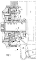
- Fig. 1 shows a longitudinal section through an oil pump according to the invention, along the line I-I in Fig. 2,
- Fig. 2 shows a front view of an oil pump according to the invention, with cap removed,
- Fig. 3 shows a section along the line III-III in Fig. 2,
- Fig. 4 shows a section along the line IV-IV in Fig. 2,
- Fig. 5 shows a section along the line V-V in Fig. 2,
- Fig.6 shows a section VI-VI in Fig. 2,
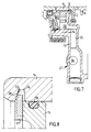
- Fig. 7 shows a section along the line VII-VII in Fig. 2, and
- Fig. 8 shows an enlarged detail of Fig. 2.
- In an
internal combustion engine 1 illustrated in Fig. 1, one end of acrankshaft 3 mounted in theengine block 2 protrudes from the latter. Starting from theengine block 2, the crankshaft end successively bears an inner sprocket 4, anouter sprocket 5, adog 6 and a belt pulley 7, all of which are fitted nonrotatably on the crankshaft end by means of a key 8. The sprocket 4 drives via a chain 9 the engine's two camshafts (not shown) and thesprocket 5 correspondingly drives via achain 10 the engine's two balancing-shafts (not shown). These two chain transmissions run in the inside of the engine, are lubricated by the engine's oil lubrication system and are enclosed in a normal manner by an end-cover 11 fastened to the end of theengine block 2. The end-cover 11 accommodates anoil pump 12 which is driven by means of thecrankshaft 3 and thedog 6 and is connected by asuction line 13 to an oil sump at the bottom of the engine. - As illustrated in Fig. 1, the end-
cover 11 is provided with a surroundingcollar 14 which faces away from theengine block 2 and supports internally acap 15. Alocking ring 17 fitted in a groove 16 in thecollar 14 holds thecap 15 in position in thecollar 14. Thecap 15 seals partly by means of aseal 18 of the O-ring type placed in a circumferential groove in the cap, against the inside of thecollar 14 on the end-cover 11 and partly by means of aseal 19 of the shaft seal type against aneck 20 of the belt pulley 7. Should there be no belt pulley on this crankshaft end, thecap 15 may cover the crankshaft end. - In Fig. 2, the belt pulley 7 and the
cap 15 have been removed to show more clearly the inside of theoil pump 12. As illustrated, thedog 6 meshes with apinion 21 which meshes in turn with a centre-displaced internally toothed ring-gear 22. Thepinion 21 and the ring-gear 22 have between them in a usual manner a crescent-shaped spacing device 23 which is here integral with the end-cover 11 and is situated in the same cavity as thepinion 21 and the ring-gear 22. - The suction side of the
pump 12 is connected to the engine's oil sump via aninlet 24, asuction duct 25 and thesuction line 13. From thepump outlet 26, oil on the pump's pressure side is supplied to the lubrication points in the engine via apressure reducing valve 27 placed in thetransmission cover 11. Oil returning from thepressure reducing valve 27 can reach the pump's suction side via areturn port 28. - To reduce the load on the
seal 19 between thecap 15 and the belt pulley 7 there is in the cap 15 (see Fig. 3) adrain duct 29 to remove leakage oil. Thedrain duct 29 is connected to the engine's crankcase and oil sump via aduct 30 in the end-cover 11. - On the inside of the
cap 15 is agroove 31 which runs along thepinion 21 along part of the latter's periphery (see Figs. 1 and 2) on the pump's suction side. This groove communicates with the pump's pressure side and has the function, by means of pressurised oil, of preventing air being drawn in radially from thecrankshaft 3. The tightness of the pump is thus improved. - As shown in Fig. 4, pressurised oil runs from the
outlet 26 via aduct 32 and thepressure reducing valve 27 to adistribution duct 33 which is situated in theengine block 2 and from which it can in known manner be distributed in the engine. Theduct 32, which is horizontal, communicates via avertical duct 34 and a pressure control device not shown here in detail with areturn duct 35 via which oil can make its way back to thereturn port 28 of thepump 12. For fastening to theengine block 2, the end-cover 11 is provided with a number ofscrew holes 36, some of which are shown in Figs. 2 and 6.
The more detailed design of the arrangement for fixing thecap 15 in thecollar 14 of the end-cover 11 is illustrated in Fig. 8. Thelocking ring 17 is of the well-known Seger ring type and is held in place in the groove 16 by the fact that it springs radially outwards. Thecap 15 is thus effectively locked in thecollar 14, but is extremely easy to fit and remove. As illustrated, the wall 37 (on the left in Fig. 8) of the groove 16 is somewhat inclined so that the groove 16 broadens radially inwards. Thelocking ring 17 is of substantially rectangular cross-section but has in its radial outer portion achamfer 38 which matches the angle of inclination of, and is intended to cooperate with, thewall 37. The result is that upon radial expansion of the locking ring 17 (depicted in broken lines) it endeavours to move inwards towards theengine block 2, thereby urging thecap 15 to move in the same direction and consequently press the parts of the pump together to create between them good axial contact without play. This means that the thickness of thecap 15, as also the placing of the groove 16 in the axial direction, can be varied within certain limits without jeopardising the functioning of the pump, with consequent great advantages both during manufacture and during fitting. It is according to the invention essential that the lockingring 17 and the groove 16 cooperate in such a manner that the locking ring, when it expands in the groove, simultaneously moves towards the engine. This can also be achieved with an unchamfered locking ring but the version with chamfered locking ring illustrated is more advantageous from the force transmission point of view and creates better contact between the locking ring and the cap. The function intended can also be achieved with shapes of locking ring and groove other than shown here. - As clearly shown in Fig. 1, the belt pulley 7 may be so designed as at least partly to enclose the
collar 14, thus allowing it to be placed closer to theengine block 2 than was previously possible. This contributes to achieving a desired shorter overall engine length.
The simplified design of theoil pump 12 is advantageous from both the manufacturing and the fitting points of view. The engine end-cover and the pump housing incorporated in it can preferably be preassembled as a unit, thereby reducing engine assembling time. All that has to be done after thepinion 21 mounted in the end-cover and accompanied by the end cap has been engaged with thedog 6 is to tighten the screws of the end-cover. Inspection and servicing of the hydraulic pump are also facilitated, as all that has to be removed after the belt pulley is the locking ring and the cap. Engine assembly is also facilitated by the fact that thepressure reducing valve 27 is also incorporated in thetransmission cover 11.
Claims (6)
- Hydraulic pump of an engine with a crankshaft(3), especially oil pump of a vehicle engine, provided with a pinion(21) driven by the engine crankshaft(3) and with a ring gear(22) being enclosed in a pump housing formed by an end cover(11) fastened to the engine and by another part(15), the end cover(11) and the other part(15) have an aperture for the crankshaft(3), wherein the end cover has an axial cavity containing the pinion(21) and the ring gear (22) and a collar(14) placed around the cavity, the inside of the collar(14) centering the other part(15), which takes the form of a cap so as to close the cavity, wherein
the end cover(11) is a transmission cover, and containing at least one transmission (5,10,4,9) driven by the engine crankshaft, characterised in that
the collar(14) of the end cover(11) faces axially away from the engine and in that the collar(14) is provided with a peripheral groove(16) in which a locking ring(17) is so placed that by cooperation with the groove(16) it urges the cap towards the interior of the cavity,
that the collar(14) is surrounded radially externally by a portion of a partly socket-shaped belt pulley(7) fitted axially outside the pump(12) and driven by the crankshaft(3) so that the socket-shaped part of the belt pulley and the collar are at least partly in the same plane as one another. - Hydraulic pump according to claim 1, characterised in that the groove (16) broadens radially inwards and that the groove's side (37) is planar and is inclined radially inwards away from the cavity so that when the locking ring (17) expands radially in contact with the latter the locking ring moves towards the interior of the cavity.
- Hydraulic pump according to claim 2, characterised in that the locking ring (17) is of substantially rectangular cross-section but with a chamfer (38) on the radial outer portion of one side.
- Hydraulic pump according to any of claims 1-3, characterised in that between the inside of the collar (14) and the shell surface of the cap (15) which matches the inside of the collar there is a seal (18), suitably in the form of an O-ring seal, placed in a peripheral groove in the cap.
- Hydraulic pump according to any of claims 1-4, characterised in that the cap (15) has a hole for the outer end and that this hole has in it a seal (19) which is intended to seal against a device connected to the outer end of the crankshaft, suitably a neck portion (20) of a belt pulley (7).
- Hydraulic pump according to any of claims 1-5, characterised in that a crescent-shaped spacing device (23) intended to be located between the pinion (21) and the ring-gear (22) is integral with the endcover (11).
Applications Claiming Priority (3)
| Application Number | Priority Date | Filing Date | Title |
|---|---|---|---|
| SE9100635 | 1991-03-05 | ||
| SE9100635A SE468058B (en) | 1991-03-05 | 1991-03-05 | HYDRAULIC PUMP FOR A VEHICLE ENGINE |
| PCT/SE1992/000131 WO1992015773A1 (en) | 1991-03-05 | 1992-03-03 | Hydraulic pump for a vehicle engine |
Publications (2)
| Publication Number | Publication Date |
|---|---|
| EP0528004A1 EP0528004A1 (en) | 1993-02-24 |
| EP0528004B1 true EP0528004B1 (en) | 1995-05-17 |
Family
ID=20382054
Family Applications (1)
| Application Number | Title | Priority Date | Filing Date |
|---|---|---|---|
| EP92906271A Expired - Lifetime EP0528004B1 (en) | 1991-03-05 | 1992-03-03 | Hydraulic pump for a vehicle engine |
Country Status (6)
| Country | Link |
|---|---|
| US (1) | US5314319A (en) |
| EP (1) | EP0528004B1 (en) |
| JP (1) | JP3380548B2 (en) |
| DE (1) | DE69202533T2 (en) |
| SE (1) | SE468058B (en) |
| WO (1) | WO1992015773A1 (en) |
Families Citing this family (16)
| Publication number | Priority date | Publication date | Assignee | Title |
|---|---|---|---|---|
| US5662462A (en) * | 1995-06-07 | 1997-09-02 | Hydraulic Power Systems, Inc. | Sealing arrangement for a hydraulic motor and pump |
| DE19632024C2 (en) * | 1996-08-08 | 1998-07-02 | Daimler Benz Ag | Oil pump for an internal combustion engine |
| JP3575180B2 (en) * | 1996-08-30 | 2004-10-13 | アイシン精機株式会社 | Oil pump |
| US6244239B1 (en) | 1997-11-19 | 2001-06-12 | Simpson Industries | Integrated front end accessory drive system |
| US6183230B1 (en) * | 1999-03-19 | 2001-02-06 | General Motors Corporation | Isolated engine oil pump drive |
| JP2001295618A (en) | 2000-04-18 | 2001-10-26 | Yamaha Motor Co Ltd | Oil pump arrangement structure of internal combustion engine |
| DE102004008154B4 (en) * | 2004-02-19 | 2010-07-01 | Audi Ag | Drive arrangement for secondary drives of internal combustion engines |
| FR2879650B1 (en) * | 2004-12-21 | 2007-02-23 | Renault Sas | OIL PUMP ARRANGEMENT |
| FR2927942A1 (en) * | 2008-02-25 | 2009-08-28 | Peugeot Citroen Automobiles Sa | LUBRICATION CIRCUIT AND ASSOCIATED PUMP. |
| CN101929365B (en) * | 2010-07-30 | 2012-07-04 | 天津大学 | Hydraulic self-adaption air valve correct-timing variable system of diesel engine and control method thereof |
| US8718759B2 (en) | 2011-08-04 | 2014-05-06 | Galvani Ltd. | Multi-modal electrotherapy method and apparatus |
| US8750990B1 (en) | 2012-12-12 | 2014-06-10 | Galvani, Ltd. | Coordinated medium voltage therapy for improving effectiveness of defibrillation therapy |
| FR3014940B1 (en) * | 2013-12-17 | 2016-01-15 | Poclain Hydraulics Ind | HYDRAULIC SYSTEM WITH DRAIN CARTER |
| DE202014002634U1 (en) * | 2014-03-26 | 2015-07-01 | GM Global Technology Operations LLC (n. d. Gesetzen des Staates Delaware) | Optimized oil supply to a crankshaft |
| JP6747840B2 (en) * | 2016-03-28 | 2020-08-26 | 本田技研工業株式会社 | Power unit |
| US11981201B2 (en) * | 2019-12-18 | 2024-05-14 | TSI Products, Inc. | Accessory rotary drive system and method |
Citations (2)
| Publication number | Priority date | Publication date | Assignee | Title |
|---|---|---|---|---|
| US3303783A (en) * | 1964-07-01 | 1967-02-14 | Tuthill Pump Co | Fluid pump apparatus |
| JPS59115485A (en) * | 1982-12-22 | 1984-07-03 | Koyo Seiko Co Ltd | Pump for power steering |
Family Cites Families (7)
| Publication number | Priority date | Publication date | Assignee | Title |
|---|---|---|---|---|
| FR668805A (en) * | 1928-05-18 | 1929-11-07 | Improvements to mechanical grids | |
| DE2836766A1 (en) * | 1978-08-23 | 1980-03-06 | Volkswagenwerk Ag | INTERNAL COMBUSTION ENGINE WITH AN OIL PUMP |
| US4382756A (en) * | 1981-06-08 | 1983-05-10 | General Motors Corporation | Bearing and seal assembly for a hydraulic pump |
| DE3416400C2 (en) * | 1984-05-03 | 1993-10-07 | Schwaebische Huettenwerke Gmbh | Motor vehicle oil pump |
| IT1224053B (en) * | 1988-12-30 | 1990-09-26 | Fiat Auto Spa | INTERNAL COMBUSTION ENGINE PARTICULARLY FOR VEHICLES |
| JP2546407Y2 (en) * | 1991-02-19 | 1997-09-03 | 株式会社ユニシアジェックス | Oil pump |
| US5085187A (en) * | 1991-03-11 | 1992-02-04 | Chrysler Corporation | Integral engine oil pump and pressure regulator |
-
1991
- 1991-03-05 SE SE9100635A patent/SE468058B/en not_active IP Right Cessation
-
1992
- 1992-03-03 EP EP92906271A patent/EP0528004B1/en not_active Expired - Lifetime
- 1992-03-03 US US07/946,294 patent/US5314319A/en not_active Expired - Lifetime
- 1992-03-03 WO PCT/SE1992/000131 patent/WO1992015773A1/en not_active Ceased
- 1992-03-03 JP JP50611992A patent/JP3380548B2/en not_active Expired - Lifetime
- 1992-03-03 DE DE69202533T patent/DE69202533T2/en not_active Expired - Lifetime
Patent Citations (2)
| Publication number | Priority date | Publication date | Assignee | Title |
|---|---|---|---|---|
| US3303783A (en) * | 1964-07-01 | 1967-02-14 | Tuthill Pump Co | Fluid pump apparatus |
| JPS59115485A (en) * | 1982-12-22 | 1984-07-03 | Koyo Seiko Co Ltd | Pump for power steering |
Also Published As
| Publication number | Publication date |
|---|---|
| SE9100635L (en) | 1992-09-06 |
| WO1992015773A1 (en) | 1992-09-17 |
| US5314319A (en) | 1994-05-24 |
| SE9100635D0 (en) | 1991-03-05 |
| DE69202533D1 (en) | 1995-06-22 |
| SE468058B (en) | 1992-10-26 |
| JP3380548B2 (en) | 2003-02-24 |
| EP0528004A1 (en) | 1993-02-24 |
| DE69202533T2 (en) | 1995-12-21 |
| JPH05506291A (en) | 1993-09-16 |
Similar Documents
| Publication | Publication Date | Title |
|---|---|---|
| US5314319A (en) | Hydraulic pump for a vehicle engine | |
| US4607601A (en) | Detachable timing gear cassette unit for an explosion or internal combustion engine | |
| EP0789165B1 (en) | Rotary shaft lubricating structure | |
| US7114926B2 (en) | Water pump for cooling engine | |
| US4436067A (en) | Engine driven pump arrangement | |
| KR20030007902A (en) | Integrated power transmission drive and method | |
| US5876188A (en) | Oil pump arrangement for four-cycle outboard motor | |
| US7363904B2 (en) | Lubrication device of engine | |
| JP4063401B2 (en) | Engine oil pump structure for outboard motors | |
| US6904884B2 (en) | Balance device for engines | |
| US6161284A (en) | Method for improved service of engine mounted accessories | |
| US7293756B2 (en) | Engine fastening structure | |
| US5188072A (en) | Fuel pump designed as rotor pump | |
| GB2140083A (en) | Driving I.C. engine fuel pump and distributor | |
| US5975970A (en) | Oil pump unit for outboard motor | |
| US5267537A (en) | Lubricating structure for power transmission chain | |
| JP2000008987A (en) | Fuel pump arrangement structure for fuel injection engine | |
| US6186844B1 (en) | Outboard motor | |
| EP1489279B1 (en) | Water pump for internal combustion engine | |
| US20040136838A1 (en) | Electronic pressure relief valve for engine oil pump | |
| US6564905B1 (en) | Lubrication system for a marine engine | |
| US4444162A (en) | Internal combustion engine with a secondary aggregate | |
| JPH0248668Y2 (en) | ||
| US20070122294A1 (en) | Pump | |
| US3924577A (en) | Accessory shaft drive for a rotary machine |
Legal Events
| Date | Code | Title | Description |
|---|---|---|---|
| PUAI | Public reference made under article 153(3) epc to a published international application that has entered the european phase |
Free format text: ORIGINAL CODE: 0009012 |
|
| 17P | Request for examination filed |
Effective date: 19921124 |
|
| AK | Designated contracting states |
Kind code of ref document: A1 Designated state(s): DE GB |
|
| 17Q | First examination report despatched |
Effective date: 19940202 |
|
| GRAA | (expected) grant |
Free format text: ORIGINAL CODE: 0009210 |
|
| AK | Designated contracting states |
Kind code of ref document: B1 Designated state(s): DE GB |
|
| REF | Corresponds to: |
Ref document number: 69202533 Country of ref document: DE Date of ref document: 19950622 |
|
| PG25 | Lapsed in a contracting state [announced via postgrant information from national office to epo] |
Ref country code: GB Effective date: 19960303 |
|
| PLBE | No opposition filed within time limit |
Free format text: ORIGINAL CODE: 0009261 |
|
| STAA | Information on the status of an ep patent application or granted ep patent |
Free format text: STATUS: NO OPPOSITION FILED WITHIN TIME LIMIT |
|
| 26N | No opposition filed | ||
| GBPC | Gb: european patent ceased through non-payment of renewal fee |
Effective date: 19960303 |
|
| PGFP | Annual fee paid to national office [announced via postgrant information from national office to epo] |
Ref country code: DE Payment date: 20110328 Year of fee payment: 20 |
|
| REG | Reference to a national code |
Ref country code: DE Ref legal event code: R071 Ref document number: 69202533 Country of ref document: DE |
|
| REG | Reference to a national code |
Ref country code: DE Ref legal event code: R071 Ref document number: 69202533 Country of ref document: DE |
|
| PG25 | Lapsed in a contracting state [announced via postgrant information from national office to epo] |
Ref country code: DE Free format text: LAPSE BECAUSE OF EXPIRATION OF PROTECTION Effective date: 20120304 |