EP0526879A1 - Coordinate input apparatus - Google Patents
Coordinate input apparatus Download PDFInfo
- Publication number
- EP0526879A1 EP0526879A1 EP92113286A EP92113286A EP0526879A1 EP 0526879 A1 EP0526879 A1 EP 0526879A1 EP 92113286 A EP92113286 A EP 92113286A EP 92113286 A EP92113286 A EP 92113286A EP 0526879 A1 EP0526879 A1 EP 0526879A1
- Authority
- EP
- European Patent Office
- Prior art keywords
- vibration
- distance
- deriving
- coordinate
- derived
- Prior art date
- Legal status (The legal status is an assumption and is not a legal conclusion. Google has not performed a legal analysis and makes no representation as to the accuracy of the status listed.)
- Granted
Links
Images


Classifications
-
- G—PHYSICS
- G06—COMPUTING; CALCULATING OR COUNTING
- G06F—ELECTRIC DIGITAL DATA PROCESSING
- G06F3/00—Input arrangements for transferring data to be processed into a form capable of being handled by the computer; Output arrangements for transferring data from processing unit to output unit, e.g. interface arrangements
- G06F3/01—Input arrangements or combined input and output arrangements for interaction between user and computer
- G06F3/03—Arrangements for converting the position or the displacement of a member into a coded form
- G06F3/041—Digitisers, e.g. for touch screens or touch pads, characterised by the transducing means
- G06F3/043—Digitisers, e.g. for touch screens or touch pads, characterised by the transducing means using propagating acoustic waves
- G06F3/0433—Digitisers, e.g. for touch screens or touch pads, characterised by the transducing means using propagating acoustic waves in which the acoustic waves are either generated by a movable member and propagated within a surface layer or propagated within a surface layer and captured by a movable member
Definitions
- the present invention relates to a coordinate input apparatus and others for detecting indicated coordinates on the basis of the vibration transmission time obtainable from the vibrating source on a vibration transfer diaphragm, for example.
- the type using ultrasonic wave is such that the positioned coordinates are worked out by detecting the delay time of the wave being propagated on the tablet which serves as the input plane, and no fabrication of matrix wirings and others are needed at all on the tablet. It is therefore possible to provide an apparatus at a low manufacturing cost. Moreover, if a transparent glass plate is employed for the tablet, it is possible to construct a coordinate input apparatus having a higher transparency than the input plates using the other systems.
- the waveform of the detected signal of an output wave from its sensor are not only caused to vary its amplitude level by the attenuation of the wave due to the distances between the vibrating input pen and the sensor, but also are largely dependent on the degrees of the tool forces of the input pen exerted by an operator. Consequently, when the delay time is detected with the detected signal waveform exceeding a given level as a specific point (whose level over a given level is required in order to distinguish it from noise), the leading portion of the waveform of the detecting signal is not detected, and the second cycle and third cycle (refer to Figs.
- the point on the temporal axis lagged behind the leading portion (of the detected signal waveform) of the wave being propagated on the vibration transmission plate is made as the detection point, the wave which has advanced before the detection point is reflected at the end of the vibration transfer diaphragm and is allowed to be superposed with the detected signal waveforms by the direct wave, and accordingly, there is a possibility that the detected signal waveform for measuring the delay time is distorted. This causes the accuracy of the coordinate detection of the coordinate input apparatus to be significantly lowered.
- either the reflection at the end should be eliminated, or the distance to the end should be made longer so that the time for the reflected wave to return is delayed to avoid its superposition with the detection point in the detected signal waveform.
- Fig. 8 is a schematic view showing a relationship between the distances and the delay times in wave arrival when this wave is used with the detection points of the phase delay time being set above a predetermined level and also with the peak of the envelope given as each of the detection points of the group delay time.
- the group delay time is continuous, it has a relationship showing greater fluctuations of the widths, and the phase delay time has a stepwise relationship. Such relationships are caused by the nature of the plate wave which has different phase velocity and group velocity.
- the present invention has been made in consideration of the above-mentioned prior example. It is an object of the invention to provide an coordinate input apparatus capable of calculating coordinate accurately only with the phase information of the detecting signal waveforms without affect of the level fluctuations of the detecting signal waveforms, further the apparatus being structured compactly by saving circuits, leading to a low power consumption as well as a low cost of its fabrication.
- Fig. 1 is a structural view showing a coordinate input apparatus embodying the present invention, in which a reference numeral 8 designates a vibration transfer plate and 6, a vibration sensor comprising the piezoelectric element for detecting elastic waves.
- a reference numeral 8 designates a vibration transfer plate and 6, a vibration sensor comprising the piezoelectric element for detecting elastic waves.
- four vibration sensors 6 are provided each on every side of the circumference of the vibration transfer plate 8.
- a reference numeral 7 designates a vibration-proof member for removing reverberation of the elastic waves on the vibration transfer plate 8.
- a reference numeral 3 designates a vibrating input pen, and a piezoelectric element 4 in the vibrating input pen 3 is driven by a vibrator driving circuit 2.
- the vibrator driving circuit 2 generates pulse trains of specific frequency for a certain periodic cycle to drive a vibrator 4 in the vibrating input pen 3.
- the vibrational energy thus generated enters the vibration transfer plate 8 through a horn portion 5.
- the waves propagating on the vibration transfer plate 8 are detected by the vibration sensor 6 and are amplified by preamplifier circuits 9 to 12 and then inputted into waveform detection circuits 13 to 16.
- the waveform detection circuits 13 to 16 detect an arrival timing of given waveform components by waveform processing of each detection signal, thus enabling latch circuits 17 to 20 to latch the timing information from a time counter 21 in accordance with this detection output.
- the timing information thus latched by the latch circuits 17 to 20, namely the arrival delay time information of the elastic wave from its input point to each vibratory sensor 6, is inputted into a controller 1 comprising a microcomputer and others.
- the controller 1 calculates the coordinates at the input point from said latched timing information in such a manner as described later and inputs the information into some other information processing apparatus for example, a personal computer.
- a reference numeral 31 designates a microcomputer for constituting the controller 1 and having ROM, RAM and internal counter.
- the microcomputer 31 resets the latch circuits 17 to 20 and time counter 21 by a clear signal at first.
- a pen down detection circuit 22 detects a vibration waveform generated when the vibrating input pen 3 contacts with the vibration transfer plate 8, whereby the vibrating input pen 3 is put down on the vibration transfer plate 8.
- the pen down detection circuit 22 is reset by a clear signal for detecting a new pen down signal.
- the latch circuits 17 to 20 clear the contents latched.
- the time counter 21 clears its counted value to be in the standby state for a starting signal to be inputted.
- the microcomputer 31 transmits the starting signal to the vibrator driving circuit 2 and the time counter 21 as well.
- the vibrator driving circuit 2 With this starting signal, the vibrator driving circuit 2 generates pulse trains of a given frequency to drive the piezoelectric element 4.
- the time counter 21 starts counting with clock of a frequency suited for required resolution.
- the distance from the vibrating input pen 3 to each vibration sensor 6 which should be obtained at first for calculating coordinates is derived on the basis of the product of the propagating velocity of an elastic wave and the arrival delay time of the elastic wave. Therefore, in order to enhance the resolution of the distance measurement, it is necessary either to slow down the propagating velocity of the elastic wave or to heighten the frequency of the aforesaid clock.
- the elastic wave generated by the vibrations of the vibrating input pen 3 is converted into electrical signal by each vibration sensor 6 and inputted into the waveform detection circuits 13 to 16 through the preamplifier circuits 9 to 12.
- the latch circuits 17 to 20 take in the outputs of the time counter 21 with the output signals from each waveform detection circuit being used as trigger, and output the values to the microcomputer 31.
- the microcomputer 31 performs processing (described later) from these data to calculate coordinate values and then transfer them to a host information processing apparatus through an input/output port 33 (comprising RS-232C port and others, for example).
- Fig. 3 is a view showing the signal waveforms from the vibration sensors 6 inputted into the waveform detection circuits 13 to 16 and the measuring processing of vibrational propagation delay time on the basis thereof.
- the waveform shown at 41 shows the pulses of the driving signal applied to the piezoelectric element 4 in the vibrating input pen 3. In the present embodiment, it is driven by a pulse train of (equivalent to five cycles) of 300 KHz.
- the ultrasonic wave vibration driven by such driving signal and inputted into the vibration transfer diaphragm 8 from the vibrating input pen 3 is detected by the vibration sensor 6 after the elapse of a time corresponding to the straight-line distance to the vibration sensor 6, and then output electrically.
- a reference numeral 42 shows the detection signal waveform output by the vibration sensor 6.
- a reference numeral 43 indicates a state where the window is opened with the location where the level of the detection signal waveform becomes higher than a given value as the reference; and 44, the signal for measuring a delay time tp which makes the zero cross its detection point, at which the phase information of the detection signal waveform rises initially from the state where the window at 43 having been opened.
- the propagation delay times obtainable from the amplitude levels of the output detection signal waveforms become different even if the distances between the vibrating input pen 3 and the vibration sensors 6 are the same. This occurs because the window for detecting the delay time tp is opened (Fig. 7) using a threshold value, and as the difference in the detected propagation delay times is equivalent to a value integral times a cycle 7 of the elastic wave, a delay time required is given by following equation (3):
- One of the tentative delay times T given by this value n can be a genuine delay time. Therefore, by obtaining the value n, the distance L between a certain vibration sensor 6 and the vibrating input pen 3 can be obtained by following equation provided that the frequency of plate wave is f: where
- the integer n is determined by the amplitude of vibration detected by each sensor and the threshold value, and the distance between the vibrating input pen 3 and the vibration sensor 6. Accordingly, if differs by each sensor.
- Fig. 4 is a view showing the positions of sensors in the present embodiment.
- Two vibration sensors 6 oppositely positioned are made a pair, and two pairs of sensors X1 ' X2 and Y1 ' Y2 are arranged orthogonally to calculate coordinates.
- the vibrating input pen 3 indicates a point A at cooridnates (X, Y) to obtain its coordinate value
- the real distance from the indicated point A to the Y1 vibration sensor 6 is given as dY1; to the Y2 vibration sensor 6, as dY2; to the X1 vibration sensor 6, as dX1; and, to the X2 sensor 6, as dX2.
- the coordinate system is arranged as shown in Fig.
- the coordinate value A (X, Y) is obtained in the procedures given below provided that the distance between the Y1 vibration sensor 6 and the Y2 vibration sensor 6 is defined as y, and the distance between the X1 vibration sensor 6 and the X2 vibration sensor 6, as x.
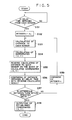
- Fig. 5 is a flowchart showing the flow of processes to calculate the coordinate value. In conjunction with Fig. 5, the processing procedures will be described.
- the microcomputer 31 obtains the phase delay time by the latch circuits 17 to 20 from each of the four sensors 6 (S51 - YES), this value and the known phase velocity are applied to the equation (4) to calculate the tentative distance from the vibration sensor 6 and the vibrating input pen 3.
- the second term of the equation (4) cannot be defined at this stage. Therefore, the tentative initial values no to no4 (represented by no) are obtained (S52) for each vibration sensors 6 in advance by a method which will be described later, and are substituted to the equation (4) (S53).
- the distance LY1 from the point A to Y1 sensor is obtained according to the delay time tp 1 measured by Y1 sensor and the tentative initial value n01.
- the distance LY2 is calculated according to the delay time tp 2 and the initial value no2 of n. Then, these values LY1 and LY2 are applied to the equation (5) to calculate the Y coordinate. In the same way, the distances LX1 and LX2 from the point A to X1 sensor and X2 sensor are obtained, and using the equation (6), the X coordinate is calculated (S54).
- Y and X are values obtained from the two pairs of vibration sensors, a pair of Y1 and Y2, and a pair of X1 and X2, respectively, and are the values obtained independently. Therefore, when the distances to each of the vibration sensors 6, RLY1 and RLY2, and RLX1 and RLX2, are reversely calculated by the equations (7) to (10) described later, using the tentative coordinate value (X, Y) at the point A thus obtained here, they are not necessarily matched with the distances LY1 and LY2, and LX1 and LX2 calculated from the phase delay times and the initial values no - (because the second term of the equation (4) has not been defined as yet).
- the reversely calculated distances from the point A to each of the sensors, RLY1, RLY2, RLX1 and RLX2, are obtained (S55) by the equations (7) to (10) and then the distances LY1, LY2, LX1, and LX2 obtained from the phase delay times and initial values no (S53) and the values obtained in the step S55 are compared, respectively (S56). If each of them is found to be matched within the predetermined range of error (S57 - YES), the coordinate input apparatus outputs the coordinates (X, Y) at that time as established coordinates or writes such value into its inner memory (S58). Also, if the values are not matched (S57 - NO), integers are added to or subtracted from the initial values no of n to set integers n again (S59) and the calculations (equations (4) to (10)) are again performed.
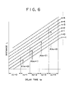
- Fig. 6 is a view showing the relations between the delay times tp and distances L when a tool force is within a given range (solid lines in Fig. 6). If the tool force is weakened so that the levels of the detecting signal waveforms are significantly changed, the relationship represented by broken lines in Fig. 6 is also shown. Therefore, in an normal operation, there is a more probability that the relationship is such as indicated by the solid lines.
- the initial values no of integers n are given with the relations shown in Fig. 6 (the value of the initial value no being made larger as the delay time becomes longer) on the basis of the detected delay times, hence implementing to shorten the calculation time.
- the initial value no is defined in such manner. However, it may be possible to adopt a method for the definition of no in which it is delimitated at each of the points A in Fig. 6, for example, as a matter of course.
- a coordinate input apparatus using a pen for indicating coordinates its tool force fluctuations cannot be avoided when it is in use.
- the level fluctuations of the detection signal waveforms cannot be avoided, either. Therefore, it is impossible to detect the definite point of a detection signal waveform (the leading portion of a detection signal, for example) without fail all the time.
- the present embodiment is applicable to a coordinate input apparatus using not only plate wave, but also elastic wave such as surface wave or Love wave.
- plate wave described in the present embodiment are unique in that its phase velocity and group velocity are different and the phases in the detection signal waveforms are being deviated, but they can serve as an excellent coordinate calculating means without affect of the problem resulting from the levels of the detection signal waveforms or the peculiarity of plate wave.
- a coordinate input apparatus is not affected by the level fluctuations of the detection signal waveforms, that is, the attenuation of the elastic waves which are dependent on the distances from a vibrating input pen to each vibration sensor, the tool forces of the vibration pen at the time of coordinate input, or various other factors resulting in the level fluctuations, therefore, it is possible to calculate the coordinates accurately only in accordance with the phase information of the detection signal waveforms.
- plate wave having different group velocity and phase velocity as an elastic wave. Since plate wave has slower phase velocity than elastic wave such surface wave, its accuracy of distance detection can be enhanced if the resolution of the counter is the same for measuring the delay times. It is thus possible to obtain a resultant effect that the accuracy of the coordinates calculated by the coordinate input apparatus is also enhanced. Further, with a structure according to the present embodiment, it is possible to reduce the analogue circuits significantly because the coordinates are calculated only in accordance with the phase information available within the detection signal waveforms, hence leading to a lower power consumption and a lower cost in manufacturing and in operation.
- the detection points can be shifted closer to the leading portion of the detection signal waveforms in the present embodiment.
- the influence of the reflection waves from the end portion of the vibration transfer diaphragm becomes smaller, thus making it possible to reduce the size of the vibration transfer diaphragm itself significantly in relation to the effective area where the coordinate input can be conducted.
- the apparatus can be made compact.
- the present invention is applicable not only to a system comprising a plurality of equipment and devices, but also to an apparatus of single equipment and device. Further, it is needless to mention that the present invention is applicable to a case where the requirements are met by providing a system or an apparatus with programs.
- a coordinate input apparatus can calculate coordinates accurately only in accordance with the phase information of the detection signal waveforms without being affected by the level fluctuations of the detection signal waveform. Further, it is possible to save circuits, hence implementing a low power consumption and a low cost in manufacturing and operation as well as the make the apparatus compact.
- a coordinate input apparatus including a vibrating input pen 3, a piezoelectric element 4 in the pen 3, a vibration transfer plate 8 and vibration sensors 6 provided around the vibration transfer plate 8.
- the vibrator 4 is driven by a vibrator driving circuit 2 to generate a vibration, which is transmitted to vibration transfer plate 8.
- the apparatus is capable of calculating coordinate thereon accurately with phase information of detected signal waveform.
Abstract
Description
- The present invention relates to a coordinate input apparatus and others for detecting indicated coordinates on the basis of the vibration transmission time obtainable from the vibrating source on a vibration transfer diaphragm, for example.
- As apparatuses for inputting the conventional handwritten characters, graphic and the like into a computer and other processing apparatuses, there have been known coordinate input apparatuses using various kinds of input pens, tables, and others. In such apparatus, the image information consisting of inputted characters, graphics, and the like is output for being displayed on a display device such as a CRT display or a recording device such as a printer. Of these coordinate input apparatuses, various systems such as given below are known as the coordinate detection methods for the tablet type coordinate input apparatus.
- (1) A system comprising a resistive film and a sheet material correspondingly arranged therefor to detect coordinate value by change in the resistance value at compressed point.
- (2) A system for detecting coordinate position in accordance with the electromagnetic or electrostatic induction of conductive sheet arranged facing each other.
- (3) A system for detecting coordinate position of an input pen on the basis of ultrasonic vibration transmitted from the input pen to a tablet.
- There are, however, the drawbacks given below in the conventional coordinate input apparatuses adopting these systems.
- For the above-mentioned type using the resistive film (Case: (1)). The uniformity of the resistor itself affects the input accuracy of the graphics directly, thus necessitating resistors of an excellent uniformity. Therefore, the larger the apparatus becomes, the more difficult it is to produce the apparatus, and eventually, this system is not suited for any apparatus which requires high precisions. Also, two resistive sheets are needed for the x-coordinate and y-coordinate, which results in the lowered transparency of the coordinate input plane. As a result, when the apparatus is overlaid with a manuscript or the like for use, there is a drawback that it is not easy to see the manuscript.
- Next, for the type which utilizes the electromagnetic induction (Case: (2)), wirings are arranged in matrix. The coordinate detection accuracy is directly affected by the positions of the wirings arranged in matrix, namely, the manufacturing precision. Thus, for a highly precise input apparatus, the manufacturing cost becomes extremely high.
- As compared with these systems, the type using ultrasonic wave is such that the positioned coordinates are worked out by detecting the delay time of the wave being propagated on the tablet which serves as the input plane, and no fabrication of matrix wirings and others are needed at all on the tablet. It is therefore possible to provide an apparatus at a low manufacturing cost. Moreover, if a transparent glass plate is employed for the tablet, it is possible to construct a coordinate input apparatus having a higher transparency than the input plates using the other systems.
- However, in the conventional ultrasonic coordinate input apparatus, the waveform of the detected signal of an output wave from its sensor are not only caused to vary its amplitude level by the attenuation of the wave due to the distances between the vibrating input pen and the sensor, but also are largely dependent on the degrees of the tool forces of the input pen exerted by an operator. Consequently, when the delay time is detected with the detected signal waveform exceeding a given level as a specific point (whose level over a given level is required in order to distinguish it from noise), the leading portion of the waveform of the detecting signal is not detected, and the second cycle and third cycle (refer to Figs. 7A to 7C) are output depending on the levels of the detected signal waveforms, thus creating a drawback that the coordinates are erroneously detected. In order to solve this problem, it is electrically possible to adopt a method of making the levels of the detected signal waveforms constant, but this creates another problem that the cost will be significantly increased due to an increased number of circuit parts. Besides, the reference signal data are needed for the determination of amplification factor. As a result, not all the inputted data can be used for the coordinate calculation. In other words, a problem is encountered in lowering the sampling rate for working out the coordinates.
- In order to detect the delay time while taking these problems into account, it is necessary to adopt a method that can be practiced without depending on the amplitude levels of the detected signal waveforms. For solving these problems, it is conceivable to adopt a method for measuring the delay time in such a manner that the envelope of the detected signal waveforms is electrically derived and processed by differentiation or the like to make the envelope peak or the inflexion point of the envelope as the specific point for detection. But there arises a problem for this method that analogue circuits must be additionally provided for producing the envelope as well as for obtaining the peak value thereof, leading to another cost up. Also, a disadvantage such as an increased power consumption will result. As a more significant problem, since the point on the temporal axis lagged behind the leading portion (of the detected signal waveform) of the wave being propagated on the vibration transmission plate is made as the detection point, the wave which has advanced before the detection point is reflected at the end of the vibration transfer diaphragm and is allowed to be superposed with the detected signal waveforms by the direct wave, and accordingly, there is a possibility that the detected signal waveform for measuring the delay time is distorted. This causes the accuracy of the coordinate detection of the coordinate input apparatus to be significantly lowered. In order to solve this problem, either the reflection at the end should be eliminated, or the distance to the end should be made longer so that the time for the reflected wave to return is delayed to avoid its superposition with the detection point in the detected signal waveform. It is possible to reduce the level of the reflected wave in the former method of the solution by the use of a vibration-proof material and the like, but it is technically difficult to eliminate the reflected wave completely. Also, for the latter method of the solution, a certain length of distance is needed to the end, which necessitates making the size of the vibration transfer diaphragm greater for the effective area required to input the coordinates, thus resulting in a drawback that the apparatus becomes large as a whole.
- Also, in a coordinate input apparatus utilizing the ultrasonic waves, it is well known that if the wavelength of elastic wave propagating on a vibration transfer diaphragm becomes greater than the diaphragm thickness, plate (Lamb) wave is often propagated with difference in its group velocity and phase velocity. Fig. 8 is a schematic view showing a relationship between the distances and the delay times in wave arrival when this wave is used with the detection points of the phase delay time being set above a predetermined level and also with the peak of the envelope given as each of the detection points of the group delay time. Although the group delay time is continuous, it has a relationship showing greater fluctuations of the widths, and the phase delay time has a stepwise relationship. Such relationships are caused by the nature of the plate wave which has different phase velocity and group velocity. In this case, it is impossible to perform a measurement with any desirable accuracy by distance calculation using only the group delay time. When a distance is calculated with the phase delay time, the relationship between the phase delay time and the distance still remains in the stepwise form as shown in Fig. 8 even if the levels of the detecting signal waveforms are made constant electrically to remove the sonic wave attenuation and the effect of the tool force dependence. In other words, there is a drawback that if, for example, a value to is output in Fig. 8, it is impossible to determine whether the distance is 1, or 12.
- In order to solve this problem, there has been proposed a method of calculating coordinates by detecting both the group delay time and phase delay time of a diaphragm wave as disclosed in the Japanese Patent Publication No. 61-149742 and Japanese Patent Publication No. 61-245475, which are both prior applications hereof. In this method, given a distance between a sensor and a vibration input source as L, distance to each sensor is calculated as follows:


- Vp : phase velocity of plate wave
- Tp : phase delay time
- Vg : group velocity of plate wave
- Tg : group delay time
- xp : wavelength of plate wave
- The present invention has been made in consideration of the above-mentioned prior example. It is an object of the invention to provide an coordinate input apparatus capable of calculating coordinate accurately only with the phase information of the detecting signal waveforms without affect of the level fluctuations of the detecting signal waveforms, further the apparatus being structured compactly by saving circuits, leading to a low power consumption as well as a low cost of its fabrication.
- It is another object of the present invention to provide an ultrasonic coordinate input apparatus capable of calculating coordinates with a high precision without affect of the attenuation of elastic wave dependent on the distance between a vibration input source and each vibration sensor, the tool force of a vibration pen, and the like.
- It is still another object of the present invention to provide an ultrasonic coordinate input apparatus capable of significantly reducing the size of its vibration transfer diaphragm in relation to the effective area where the coordinate input is possible without any noticeable effect of reflection waves from end portion of the vibration transfer diaphragm.
-
- Fig. 1 is a block circuitry diagram showing the entire structure of a coordinate input apparatus according to the present invention.
- Fig. 2 is a block circuitry diagram showing the coordinate detection system of a coordinate input apparatus according to the present invention.
- Fig. 3 is a time chart for signal processes according to the present invention.
- Fig. 4 is a view showing the coordinate system of a coordinate input apparatus according to the present invention.
- Fig. 5 is a flowchart showing the coordinate calculation processes according to the present invention.
- Fig. 6 is a graph showing relations between distances and detection delay times.
- Figs. 7A to 7C are views for explaining the dependence of detection delay times on the levels of signal waveforms.
- Fig. 8 is graph showing relationship between the phase delay time and group delay time of a plate wave, and distances.
- Hereinafter, in accordance with embodiments shown in the accompanying drawings, the present invention will be described in detail.
- Fig. 1 is a structural view showing a coordinate input apparatus embodying the present invention, in which a
reference numeral 8 designates a vibration transfer plate and 6, a vibration sensor comprising the piezoelectric element for detecting elastic waves. In the present embodiment, fourvibration sensors 6 are provided each on every side of the circumference of thevibration transfer plate 8. Areference numeral 7 designates a vibration-proof member for removing reverberation of the elastic waves on thevibration transfer plate 8. Areference numeral 3 designates a vibrating input pen, and apiezoelectric element 4 in the vibratinginput pen 3 is driven by avibrator driving circuit 2. Thevibrator driving circuit 2 generates pulse trains of specific frequency for a certain periodic cycle to drive avibrator 4 in the vibratinginput pen 3. The vibrational energy thus generated enters thevibration transfer plate 8 through ahorn portion 5. The waves propagating on thevibration transfer plate 8 are detected by thevibration sensor 6 and are amplified bypreamplifier circuits 9 to 12 and then inputted intowaveform detection circuits 13 to 16. Thewaveform detection circuits 13 to 16 detect an arrival timing of given waveform components by waveform processing of each detection signal, thus enablinglatch circuits 17 to 20 to latch the timing information from atime counter 21 in accordance with this detection output. The timing information thus latched by thelatch circuits 17 to 20, namely the arrival delay time information of the elastic wave from its input point to eachvibratory sensor 6, is inputted into acontroller 1 comprising a microcomputer and others. Thecontroller 1 calculates the coordinates at the input point from said latched timing information in such a manner as described later and inputs the information into some other information processing apparatus for example, a personal computer. - Now, in conjunction with Fig. 2, the description will be made of details of controls performed for each circuit by the
controller 1. In Fig. 2, areference numeral 31 designates a microcomputer for constituting thecontroller 1 and having ROM, RAM and internal counter. Themicrocomputer 31 resets thelatch circuits 17 to 20 andtime counter 21 by a clear signal at first. - A pen down
detection circuit 22 detects a vibration waveform generated when the vibratinginput pen 3 contacts with thevibration transfer plate 8, whereby the vibratinginput pen 3 is put down on thevibration transfer plate 8. The pen downdetection circuit 22 is reset by a clear signal for detecting a new pen down signal. Thelatch circuits 17 to 20 clear the contents latched. Also, thetime counter 21 clears its counted value to be in the standby state for a starting signal to be inputted. - Then, the
microcomputer 31 transmits the starting signal to thevibrator driving circuit 2 and thetime counter 21 as well. With this starting signal, thevibrator driving circuit 2 generates pulse trains of a given frequency to drive thepiezoelectric element 4. Also, thetime counter 21 starts counting with clock of a frequency suited for required resolution. The distance from the vibratinginput pen 3 to eachvibration sensor 6 which should be obtained at first for calculating coordinates is derived on the basis of the product of the propagating velocity of an elastic wave and the arrival delay time of the elastic wave. Therefore, in order to enhance the resolution of the distance measurement, it is necessary either to slow down the propagating velocity of the elastic wave or to heighten the frequency of the aforesaid clock. However, when the frequency of the clock is heightened, the electronic parts should follow such a heightened velocity, leading to a higher cost apparatus. Therefore, in the present embodiment, using a comparatively slow plate wave having a frequency of approximately 300 KHz (the thickness of the vibration transfer diaphragm being 1.2 to 1.6), a coordinate input apparatus of high resultant resolution is implemented at a low cost. - Now, the elastic wave generated by the vibrations of the vibrating
input pen 3 is converted into electrical signal by eachvibration sensor 6 and inputted into thewaveform detection circuits 13 to 16 through thepreamplifier circuits 9 to 12. Thelatch circuits 17 to 20 take in the outputs of thetime counter 21 with the output signals from each waveform detection circuit being used as trigger, and output the values to themicrocomputer 31. Themicrocomputer 31 performs processing (described later) from these data to calculate coordinate values and then transfer them to a host information processing apparatus through an input/output port 33 (comprising RS-232C port and others, for example). - Continuously, in order to obtain the next coordinate values at the input point, which are being inputted in succession, said control is repeated starting with the clear operation of the latch circuits and time counter as well. In this case, if no detection signal is output even after the propagation delay time (maximum value) of the elastic wave elapses at the point where the distance between the vibrating
input pen 3 and thevibration sensor 6 becomes maximum after the vibratinginput pen 3 has been driven (that is, the starting signal has been output), the vibratinginput pen 3 is in a state where it is apart from thevibration transfer plate 8, that is, the time the pen is up. Accordingly, the measurement of the propagation delay time is cut off and the control will be repeated starting with the aforesaid clear operations. - With the control and processing set forth above, it is possible to detect the indication point coordinates on real time.
- Fig. 3 is a view showing the signal waveforms from the
vibration sensors 6 inputted into thewaveform detection circuits 13 to 16 and the measuring processing of vibrational propagation delay time on the basis thereof. In Fig. 3, the waveform shown at 41 shows the pulses of the driving signal applied to thepiezoelectric element 4 in the vibratinginput pen 3. In the present embodiment, it is driven by a pulse train of (equivalent to five cycles) of 300 KHz. The ultrasonic wave vibration driven by such driving signal and inputted into thevibration transfer diaphragm 8 from the vibratinginput pen 3 is detected by thevibration sensor 6 after the elapse of a time corresponding to the straight-line distance to thevibration sensor 6, and then output electrically. Areference numeral 42 shows the detection signal waveform output by thevibration sensor 6. Areference numeral 43 indicates a state where the window is opened with the location where the level of the detection signal waveform becomes higher than a given value as the reference; and 44, the signal for measuring a delay time tp which makes the zero cross its detection point, at which the phase information of the detection signal waveform rises initially from the state where the window at 43 having been opened. - According to this structure, the propagation delay times obtainable from the amplitude levels of the output detection signal waveforms become different even if the distances between the vibrating
input pen 3 and thevibration sensors 6 are the same. This occurs because the window for detecting the delay time tp is opened (Fig. 7) using a threshold value, and as the difference in the detected propagation delay times is equivalent to a value integral times a cycle 7 of the elastic wave, a delay time required is given by following equation (3):
- tp : propagation delay time output by the present detection system
- n : integer
- One of the tentative delay times T given by this value n can be a genuine delay time. Therefore, by obtaining the value n, the distance L between a
certain vibration sensor 6 and the vibratinginput pen 3 can be obtained by following equation provided that the frequency of plate wave is f:
- Vp : phase velocity of plate wave
- xp : wavelength of plate wave ( Vp/f = Vp' 7)
- Therefore, it is possible to calculate the distance L accurately if the integer n can be obtained. Hereinafter, the method of this calculation will be described. The integer n is determined by the amplitude of vibration detected by each sensor and the threshold value, and the distance between the vibrating
input pen 3 and thevibration sensor 6. Accordingly, if differs by each sensor. - Fig. 4 is a view showing the positions of sensors in the present embodiment. Two
vibration sensors 6 oppositely positioned are made a pair, and two pairs of sensors X1 ' X2 and Y1 ' Y2 are arranged orthogonally to calculate coordinates. Now, where the vibratinginput pen 3 indicates a point A at cooridnates (X, Y) to obtain its coordinate value, the real distance from the indicated point A to theY1 vibration sensor 6 is given as dY1; to theY2 vibration sensor 6, as dY2; to theX1 vibration sensor 6, as dX1; and, to theX2 sensor 6, as dX2. Also, the coordinate system is arranged as shown in Fig. 4, the coordinate value A (X, Y) is obtained in the procedures given below provided that the distance between theY1 vibration sensor 6 and theY2 vibration sensor 6 is defined as y, and the distance between theX1 vibration sensor 6 and theX2 vibration sensor 6, as x. - Fig. 5 is a flowchart showing the flow of processes to calculate the coordinate value. In conjunction with Fig. 5, the processing procedures will be described.
- At first, when the
microcomputer 31 obtains the phase delay time by thelatch circuits 17 to 20 from each of the four sensors 6 (S51 - YES), this value and the known phase velocity are applied to the equation (4) to calculate the tentative distance from thevibration sensor 6 and the vibratinginput pen 3. The second term of the equation (4) cannot be defined at this stage. Therefore, the tentative initial values no to no4 (represented by no) are obtained (S52) for eachvibration sensors 6 in advance by a method which will be described later, and are substituted to the equation (4) (S53). Now, firstly, the distance LY1 from the point A to Y1 sensor is obtained according to the delay time tp1 measured by Y1 sensor and the tentative initial value n01. Likewise, for Y2 sensor, the distance LY2 is calculated according to the delay time tp2 and the initial value no2 of n. Then, these values LY1 and LY2 are applied to the equation (5) to calculate the Y coordinate. In the same way, the distances LX1 and LX2 from the point A to X1 sensor and X2 sensor are obtained, and using the equation (6), the X coordinate is calculated (S54).

- These values Y and X are values obtained from the two pairs of vibration sensors, a pair of Y1 and Y2, and a pair of X1 and X2, respectively, and are the values obtained independently. Therefore, when the distances to each of the
vibration sensors 6, RLY1 and RLY2, and RLX1 and RLX2, are reversely calculated by the equations (7) to (10) described later, using the tentative coordinate value (X, Y) at the point A thus obtained here, they are not necessarily matched with the distances LY1 and LY2, and LX1 and LX2 calculated from the phase delay times and the initial values no - (because the second term of the equation (4) has not been defined as yet).


- RLY1 : reversely calculated distance from point A to Y1 sensor
- RLY2 : reversely calculated distance from point A to Y2 sensor
- RLX1 : reversely calculated distance from point A to X1 sensor
- RLX2 : reversely calculated distance from point A to X2 sensor
- sqrt (S) : S's positive square root
- Now, the reversely calculated distances from the point A to each of the sensors, RLY1, RLY2, RLX1 and RLX2, are obtained (S55) by the equations (7) to (10) and then the distances LY1, LY2, LX1, and LX2 obtained from the phase delay times and initial values no (S53) and the values obtained in the step S55 are compared, respectively (S56). If each of them is found to be matched within the predetermined range of error (S57 - YES), the coordinate input apparatus outputs the coordinates (X, Y) at that time as established coordinates or writes such value into its inner memory (S58). Also, if the values are not matched (S57 - NO), integers are added to or subtracted from the initial values no of n to set integers n again (S59) and the calculations (equations (4) to (10)) are again performed.
- With the above-mentioned procedures, the aforesaid calculations are repeated while modifying the values of the integers n for each sensor until each of the values, RLY1, RLY2, RLX1, and RLX2, and each of the values, LY1, LY2, LX1, and LX2, becomes equal. Then, the distances LY1, Y2, LX1, and LX2 obtianed from the phase delay times will become equal to the real distances dY1, dY2, dX1, and dX2.
- In this way, it is possible to determine the coordinates at the point A. Now, the description will be made of a method of selecting the tentative values for the integers n in order to determine the second term of the equation (4).
- Fig. 6 is a view showing the relations between the delay times tp and distances L when a tool force is within a given range (solid lines in Fig. 6). If the tool force is weakened so that the levels of the detecting signal waveforms are significantly changed, the relationship represented by broken lines in Fig. 6 is also shown. Therefore, in an normal operation, there is a more probability that the relationship is such as indicated by the solid lines. In the present embodiment, the initial values no of integers n are given with the relations shown in Fig. 6 (the value of the initial value no being made larger as the delay time becomes longer) on the basis of the detected delay times, hence implementing to shorten the calculation time. In the present embodiment, the initial value no is defined in such manner. However, it may be possible to adopt a method for the definition of no in which it is delimitated at each of the points A in Fig. 6, for example, as a matter of course.
- Now, in the present embodiment, the description has been made of plate wave. In a coordinate input apparatus using a pen for indicating coordinates, its tool force fluctuations cannot be avoided when it is in use. Thus, the level fluctuations of the detection signal waveforms cannot be avoided, either. Therefore, it is impossible to detect the definite point of a detection signal waveform (the leading portion of a detection signal, for example) without fail all the time. The present embodiment is applicable to a coordinate input apparatus using not only plate wave, but also elastic wave such as surface wave or Love wave. Also, plate wave described in the present embodiment are unique in that its phase velocity and group velocity are different and the phases in the detection signal waveforms are being deviated, but they can serve as an excellent coordinate calculating means without affect of the problem resulting from the levels of the detection signal waveforms or the peculiarity of plate wave.
- Thus, a coordinate input apparatus according to the present embodiment is not affected by the level fluctuations of the detection signal waveforms, that is, the attenuation of the elastic waves which are dependent on the distances from a vibrating input pen to each vibration sensor, the tool forces of the vibration pen at the time of coordinate input, or various other factors resulting in the level fluctuations, therefore, it is possible to calculate the coordinates accurately only in accordance with the phase information of the detection signal waveforms.
- Moreover, according to the present structure, it is possible to use plate wave having different group velocity and phase velocity as an elastic wave. Since plate wave has slower phase velocity than elastic wave such surface wave, its accuracy of distance detection can be enhanced if the resolution of the counter is the same for measuring the delay times. It is thus possible to obtain a resultant effect that the accuracy of the coordinates calculated by the coordinate input apparatus is also enhanced. Further, with a structure according to the present embodiment, it is possible to reduce the analogue circuits significantly because the coordinates are calculated only in accordance with the phase information available within the detection signal waveforms, hence leading to a lower power consumption and a lower cost in manufacturing and in operation. Also, as compared with the conventional apparatus which uses the envelope peaks of the detection signal waveforms as detection points, the detection points can be shifted closer to the leading portion of the detection signal waveforms in the present embodiment. As a result, the influence of the reflection waves from the end portion of the vibration transfer diaphragm becomes smaller, thus making it possible to reduce the size of the vibration transfer diaphragm itself significantly in relation to the effective area where the coordinate input can be conducted. There is an excellent advantage that the apparatus can be made compact.
- In this respect, the present invention is applicable not only to a system comprising a plurality of equipment and devices, but also to an apparatus of single equipment and device. Further, it is needless to mention that the present invention is applicable to a case where the requirements are met by providing a system or an apparatus with programs.
- As described above, a coordinate input apparatus according to the present invention can calculate coordinates accurately only in accordance with the phase information of the detection signal waveforms without being affected by the level fluctuations of the detection signal waveform. Further, it is possible to save circuits, hence implementing a low power consumption and a low cost in manufacturing and operation as well as the make the apparatus compact.
- Disclosed is a coordinate input apparatus including a vibrating
input pen 3, apiezoelectric element 4 in thepen 3, avibration transfer plate 8 andvibration sensors 6 provided around thevibration transfer plate 8. Thevibrator 4 is driven by avibrator driving circuit 2 to generate a vibration, which is transmitted tovibration transfer plate 8. The apparatus is capable of calculating coordinate thereon accurately with phase information of detected signal waveform.
On the basis of this information, the coordinates are worked out geometrically. This method is an excellent method because with it not only the aforesaid problem can be solved, but also the coordinates can be calculated without depending on the levels of the detecting signal waveforms. However, this method still has a drawback that its circuits become complicated since both the group delay time and phase delay time should be detected, accordingly, its power consumption is increased. Also, as it is necessary to detect the group delay time, the apparatus should unavoidably become greater as a whole in relation to its effective area.
Claims (14)
Applications Claiming Priority (2)
| Application Number | Priority Date | Filing Date | Title |
|---|---|---|---|
| JP195181/91 | 1991-08-05 | ||
| JP19518191A JP3053262B2 (en) | 1991-08-05 | 1991-08-05 | Coordinate input device and method |
Publications (2)
| Publication Number | Publication Date |
|---|---|
| EP0526879A1 true EP0526879A1 (en) | 1993-02-10 |
| EP0526879B1 EP0526879B1 (en) | 1995-11-02 |
Family
ID=16336802
Family Applications (1)
| Application Number | Title | Priority Date | Filing Date |
|---|---|---|---|
| EP92113286A Expired - Lifetime EP0526879B1 (en) | 1991-08-05 | 1992-08-04 | Coordinate input apparatus |
Country Status (4)
| Country | Link |
|---|---|
| US (1) | US5736979A (en) |
| EP (1) | EP0526879B1 (en) |
| JP (1) | JP3053262B2 (en) |
| DE (1) | DE69205761T2 (en) |
Cited By (5)
| Publication number | Priority date | Publication date | Assignee | Title |
|---|---|---|---|---|
| EP0784286A3 (en) * | 1996-01-10 | 1997-11-26 | Canon Kabushiki Kaisha | A coordinate input device and a control method therefor |
| EP1347365A2 (en) * | 2002-01-31 | 2003-09-24 | Fujitsu Limited | Ultrasonic length measuring apparatus and method for coordinate input |
| US6871149B2 (en) | 2002-12-06 | 2005-03-22 | New Transducers Limited | Contact sensitive device |
| US6922642B2 (en) | 2001-07-04 | 2005-07-26 | New Transducers Limited | Contact sensitive device |
| US7157649B2 (en) | 1999-12-23 | 2007-01-02 | New Transducers Limited | Contact sensitive device |
Families Citing this family (27)
| Publication number | Priority date | Publication date | Assignee | Title |
|---|---|---|---|---|
| KR100426295B1 (en) * | 1995-07-20 | 2004-05-17 | 가부시키가이샤 세가 | Image processing unit and game machine |
| JPH1165748A (en) | 1997-08-22 | 1999-03-09 | Canon Inc | Coordinate inputting device, sensor mounting structure and method therefor |
| JPH11249803A (en) * | 1998-03-03 | 1999-09-17 | Canon Inc | Coordinate input device, its control method and computer readable memory |
| JP2000284895A (en) | 1999-03-31 | 2000-10-13 | Hitachi Software Eng Co Ltd | Coordinate input pen, electronic board using it, coordinate input system and electronic board system |
| JP4532664B2 (en) * | 2000-04-07 | 2010-08-25 | キヤノン株式会社 | Coordinate input device, coordinate input method, information display system, and storage medium |
| JP4708581B2 (en) | 2000-04-07 | 2011-06-22 | キヤノン株式会社 | Coordinate input device, coordinate input instruction tool, and computer program |
| JP4590114B2 (en) * | 2001-02-08 | 2010-12-01 | キヤノン株式会社 | Coordinate input device, control method therefor, and recording medium |
| JP2002236546A (en) | 2001-02-08 | 2002-08-23 | Canon Inc | Coordinate input device and its control method, and computer-readable memory |
| JP2004192332A (en) * | 2002-12-11 | 2004-07-08 | Medical Bank Technology:Kk | Medical information transmission system |
| JP4199741B2 (en) * | 2005-02-25 | 2008-12-17 | Necディスプレイソリューションズ株式会社 | Wave receiver and wave reception determination method |
| JP4455392B2 (en) * | 2005-04-15 | 2010-04-21 | キヤノン株式会社 | Coordinate input device, control method therefor, and program |
| US7538894B2 (en) | 2005-04-15 | 2009-05-26 | Canon Kabushiki Kaisha | Coordinate input apparatus, control method thereof, and program |
| JP2008078628A (en) * | 2006-08-25 | 2008-04-03 | Canon Inc | Electronic module, and manufacturing method thereof |
| JP5024355B2 (en) * | 2009-11-06 | 2012-09-12 | カシオ計算機株式会社 | Pointed position detecting device, pointed position detecting method, display device and display control method thereof, portable information terminal, and program |
| JP4968353B2 (en) * | 2009-10-16 | 2012-07-04 | カシオ計算機株式会社 | Pointed position detecting device, pointed position detecting method and program |
| JP5460341B2 (en) * | 2010-01-06 | 2014-04-02 | キヤノン株式会社 | Three-dimensional measuring apparatus and control method thereof |
| JP5489886B2 (en) | 2010-06-30 | 2014-05-14 | キヤノン株式会社 | Coordinate input device, light receiving device in the device, and manufacturing method thereof |
| JP5725774B2 (en) | 2010-09-13 | 2015-05-27 | キヤノン株式会社 | Coordinate input device and coordinate input method |
| JP5973849B2 (en) | 2012-03-08 | 2016-08-23 | キヤノン株式会社 | Coordinate input device and sensor bar used for coordinate input device |
| JP5875445B2 (en) | 2012-03-30 | 2016-03-02 | キヤノン株式会社 | Coordinate input device |
| JP5986426B2 (en) | 2012-05-24 | 2016-09-06 | キヤノン株式会社 | Sound processing apparatus and sound processing method |
| JP6049334B2 (en) | 2012-07-12 | 2016-12-21 | キヤノン株式会社 | Detection apparatus, detection method, and program |
| JP6031293B2 (en) | 2012-08-03 | 2016-11-24 | キヤノン株式会社 | Coordinate input device, control method therefor, and program |
| JP6021531B2 (en) | 2012-08-31 | 2016-11-09 | キヤノン株式会社 | Coordinate input device, control method therefor, and program |
| JP6086741B2 (en) * | 2013-01-29 | 2017-03-01 | オリンパス株式会社 | Scanning observation apparatus and operation method thereof |
| US11358290B2 (en) | 2017-10-19 | 2022-06-14 | Canon Kabushiki Kaisha | Control apparatus, robot system, method for operating control apparatus, and storage medium |
| JP2019084601A (en) | 2017-11-02 | 2019-06-06 | キヤノン株式会社 | Information processor, gripping system and information processing method |
Citations (2)
| Publication number | Priority date | Publication date | Assignee | Title |
|---|---|---|---|---|
| EP0207527A2 (en) * | 1985-07-05 | 1987-01-07 | Hitachi, Ltd. | Coordinate input method and apparatus using elastic wave |
| EP0333219A2 (en) * | 1988-03-18 | 1989-09-20 | Canon Kabushiki Kaisha | Coordinate input apparatus |
Family Cites Families (4)
| Publication number | Priority date | Publication date | Assignee | Title |
|---|---|---|---|---|
| DE3751763T2 (en) * | 1986-06-27 | 1996-11-14 | Canon Kk | Coordinate input device |
| JPH0614310B2 (en) * | 1987-06-25 | 1994-02-23 | キヤノン株式会社 | Coordinate input device |
| DE3885521T2 (en) * | 1987-07-01 | 1994-03-17 | Canon Kk | Coordinate input device. |
| JP2502649B2 (en) * | 1988-01-28 | 1996-05-29 | キヤノン株式会社 | Coordinate input device |
-
1991
- 1991-08-05 JP JP19518191A patent/JP3053262B2/en not_active Expired - Fee Related
-
1992
- 1992-08-04 EP EP92113286A patent/EP0526879B1/en not_active Expired - Lifetime
- 1992-08-04 DE DE69205761T patent/DE69205761T2/en not_active Expired - Lifetime
-
1994
- 1994-12-13 US US08/355,437 patent/US5736979A/en not_active Expired - Lifetime
Patent Citations (2)
| Publication number | Priority date | Publication date | Assignee | Title |
|---|---|---|---|---|
| EP0207527A2 (en) * | 1985-07-05 | 1987-01-07 | Hitachi, Ltd. | Coordinate input method and apparatus using elastic wave |
| EP0333219A2 (en) * | 1988-03-18 | 1989-09-20 | Canon Kabushiki Kaisha | Coordinate input apparatus |
Cited By (11)
| Publication number | Priority date | Publication date | Assignee | Title |
|---|---|---|---|---|
| EP0784286A3 (en) * | 1996-01-10 | 1997-11-26 | Canon Kabushiki Kaisha | A coordinate input device and a control method therefor |
| US5761087A (en) * | 1996-01-10 | 1998-06-02 | Canon Kabushiki Kaisha | Coordinate input device and a control method therefor |
| US7157649B2 (en) | 1999-12-23 | 2007-01-02 | New Transducers Limited | Contact sensitive device |
| US8830211B2 (en) | 1999-12-23 | 2014-09-09 | Nvf Tech Ltd. | Contact sensitive device |
| US6922642B2 (en) | 2001-07-04 | 2005-07-26 | New Transducers Limited | Contact sensitive device |
| US8274480B2 (en) | 2001-07-04 | 2012-09-25 | New Transducers Limited | Contact sensitive device |
| EP1347365A2 (en) * | 2002-01-31 | 2003-09-24 | Fujitsu Limited | Ultrasonic length measuring apparatus and method for coordinate input |
| EP1347365A3 (en) * | 2002-01-31 | 2007-01-03 | Fujitsu Limited | Ultrasonic length measuring apparatus and method for coordinate input |
| US6871149B2 (en) | 2002-12-06 | 2005-03-22 | New Transducers Limited | Contact sensitive device |
| US7184898B2 (en) | 2002-12-06 | 2007-02-27 | New Transducers Limited | Contact sensitive device |
| US7376523B2 (en) | 2002-12-06 | 2008-05-20 | New Transducers Limited | Contact sensitive device |
Also Published As
| Publication number | Publication date |
|---|---|
| EP0526879B1 (en) | 1995-11-02 |
| US5736979A (en) | 1998-04-07 |
| DE69205761T2 (en) | 1996-05-02 |
| JPH0540570A (en) | 1993-02-19 |
| JP3053262B2 (en) | 2000-06-19 |
| DE69205761D1 (en) | 1995-12-07 |
Similar Documents
| Publication | Publication Date | Title |
|---|---|---|
| EP0526879B1 (en) | Coordinate input apparatus | |
| EP0296569B1 (en) | Coordinates input apparatus | |
| US5017913A (en) | Coordinates input apparatus | |
| JP2535626B2 (en) | Coordinate input device | |
| JPH01191922A (en) | Coordinate input device | |
| JPH0922324A (en) | Coordinates input device | |
| US4853496A (en) | Acoustic coordinate input device using a roughened surface to attenuate the surface wave component | |
| EP0367282A2 (en) | Coordinate input apparatus | |
| JP2502648B2 (en) | Coordinate input device | |
| JPH01112418A (en) | Coordinate input device | |
| JPS63245711A (en) | Coordinate input device | |
| JPS63136125A (en) | Coordinate input device | |
| JP2655704B2 (en) | Method for determining effective area in coordinate input device | |
| JP2654396B2 (en) | Coordinate input device | |
| JP3059563B2 (en) | Coordinate input device and method | |
| JPS63136127A (en) | Coordinate input device | |
| JP3171467B2 (en) | Coordinate input device and coordinate input method | |
| JPH0562772B2 (en) | ||
| JPS63136126A (en) | Coordinate input device | |
| JPS63239518A (en) | Coordinates input device | |
| JPH0648456B2 (en) | Coordinate input device | |
| JPH02130617A (en) | Coordinate input device | |
| JPH02130612A (en) | Coordinate input device | |
| JPH01236320A (en) | Coordinate input device | |
| JPS636620A (en) | Coordinate input device |
Legal Events
| Date | Code | Title | Description |
|---|---|---|---|
| PUAI | Public reference made under article 153(3) epc to a published international application that has entered the european phase |
Free format text: ORIGINAL CODE: 0009012 |
|
| AK | Designated contracting states |
Kind code of ref document: A1 Designated state(s): DE FR GB |
|
| 17P | Request for examination filed |
Effective date: 19930628 |
|
| 17Q | First examination report despatched |
Effective date: 19931112 |
|
| GRAA | (expected) grant |
Free format text: ORIGINAL CODE: 0009210 |
|
| AK | Designated contracting states |
Kind code of ref document: B1 Designated state(s): DE FR GB |
|
| REF | Corresponds to: |
Ref document number: 69205761 Country of ref document: DE Date of ref document: 19951207 |
|
| ET | Fr: translation filed | ||
| PLBE | No opposition filed within time limit |
Free format text: ORIGINAL CODE: 0009261 |
|
| STAA | Information on the status of an ep patent application or granted ep patent |
Free format text: STATUS: NO OPPOSITION FILED WITHIN TIME LIMIT |
|
| 26N | No opposition filed | ||
| REG | Reference to a national code |
Ref country code: GB Ref legal event code: IF02 |
|
| PGFP | Annual fee paid to national office [announced via postgrant information from national office to epo] |
Ref country code: GB Payment date: 20040804 Year of fee payment: 13 |
|
| PGFP | Annual fee paid to national office [announced via postgrant information from national office to epo] |
Ref country code: FR Payment date: 20040810 Year of fee payment: 13 |
|
| PG25 | Lapsed in a contracting state [announced via postgrant information from national office to epo] |
Ref country code: GB Free format text: LAPSE BECAUSE OF NON-PAYMENT OF DUE FEES Effective date: 20050804 |
|
| GBPC | Gb: european patent ceased through non-payment of renewal fee |
Effective date: 20050804 |
|
| PG25 | Lapsed in a contracting state [announced via postgrant information from national office to epo] |
Ref country code: FR Free format text: LAPSE BECAUSE OF NON-PAYMENT OF DUE FEES Effective date: 20060428 |
|
| REG | Reference to a national code |
Ref country code: FR Ref legal event code: ST Effective date: 20060428 |
|
| PGFP | Annual fee paid to national office [announced via postgrant information from national office to epo] |
Ref country code: DE Payment date: 20100831 Year of fee payment: 19 |
|
| REG | Reference to a national code |
Ref country code: DE Ref legal event code: R119 Ref document number: 69205761 Country of ref document: DE Effective date: 20120301 |
|
| PG25 | Lapsed in a contracting state [announced via postgrant information from national office to epo] |
Ref country code: DE Free format text: LAPSE BECAUSE OF NON-PAYMENT OF DUE FEES Effective date: 20120301 |