EP0526053A2 - Connector - Google Patents
Connector Download PDFInfo
- Publication number
- EP0526053A2 EP0526053A2 EP92306546A EP92306546A EP0526053A2 EP 0526053 A2 EP0526053 A2 EP 0526053A2 EP 92306546 A EP92306546 A EP 92306546A EP 92306546 A EP92306546 A EP 92306546A EP 0526053 A2 EP0526053 A2 EP 0526053A2
- Authority
- EP
- European Patent Office
- Prior art keywords
- terminals
- connector body
- mating connector
- cavity
- main
- Prior art date
- Legal status (The legal status is an assumption and is not a legal conclusion. Google has not performed a legal analysis and makes no representation as to the accuracy of the status listed.)
- Granted
Links
- 230000013011 mating Effects 0.000 claims abstract description 41
- 239000004020 conductor Substances 0.000 claims abstract description 5
- 230000008878 coupling Effects 0.000 claims description 14
- 238000010168 coupling process Methods 0.000 claims description 14
- 238000005859 coupling reaction Methods 0.000 claims description 14
- 238000009429 electrical wiring Methods 0.000 description 3
- 239000011347 resin Substances 0.000 description 2
- 229920005989 resin Polymers 0.000 description 2
Images


Classifications
-
- H—ELECTRICITY
- H01—ELECTRIC ELEMENTS
- H01R—ELECTRICALLY-CONDUCTIVE CONNECTIONS; STRUCTURAL ASSOCIATIONS OF A PLURALITY OF MUTUALLY-INSULATED ELECTRICAL CONNECTING ELEMENTS; COUPLING DEVICES; CURRENT COLLECTORS
- H01R13/00—Details of coupling devices of the kinds covered by groups H01R12/70 or H01R24/00 - H01R33/00
- H01R13/46—Bases; Cases
- H01R13/514—Bases; Cases composed as a modular blocks or assembly, i.e. composed of co-operating parts provided with contact members or holding contact members between them
-
- H—ELECTRICITY
- H01—ELECTRIC ELEMENTS
- H01R—ELECTRICALLY-CONDUCTIVE CONNECTIONS; STRUCTURAL ASSOCIATIONS OF A PLURALITY OF MUTUALLY-INSULATED ELECTRICAL CONNECTING ELEMENTS; COUPLING DEVICES; CURRENT COLLECTORS
- H01R13/00—Details of coupling devices of the kinds covered by groups H01R12/70 or H01R24/00 - H01R33/00
- H01R13/64—Means for preventing incorrect coupling
-
- H—ELECTRICITY
- H01—ELECTRIC ELEMENTS
- H01R—ELECTRICALLY-CONDUCTIVE CONNECTIONS; STRUCTURAL ASSOCIATIONS OF A PLURALITY OF MUTUALLY-INSULATED ELECTRICAL CONNECTING ELEMENTS; COUPLING DEVICES; CURRENT COLLECTORS
- H01R13/00—Details of coupling devices of the kinds covered by groups H01R12/70 or H01R24/00 - H01R33/00
- H01R13/62—Means for facilitating engagement or disengagement of coupling parts or for holding them in engagement
- H01R13/627—Snap or like fastening
-
- Y—GENERAL TAGGING OF NEW TECHNOLOGICAL DEVELOPMENTS; GENERAL TAGGING OF CROSS-SECTIONAL TECHNOLOGIES SPANNING OVER SEVERAL SECTIONS OF THE IPC; TECHNICAL SUBJECTS COVERED BY FORMER USPC CROSS-REFERENCE ART COLLECTIONS [XRACs] AND DIGESTS
- Y10—TECHNICAL SUBJECTS COVERED BY FORMER USPC
- Y10S—TECHNICAL SUBJECTS COVERED BY FORMER USPC CROSS-REFERENCE ART COLLECTIONS [XRACs] AND DIGESTS
- Y10S439/00—Electrical connectors
- Y10S439/901—Connector hood or shell
Definitions
- This invention relates to a connector used for an electrical connection in various kinds of electrical wiring.
- connectors are used in electrical wiring, in particular, various kinds of electrical devices for a motorcar.
- mating connector bodies In the latter connector, if all the mating connector bodies are formed into the same shape, the mating connector bodies will be improperly coupled to the housing. In order to prevent improper coupling, mating connector bodies are provided with ribs disposed in different positions in the bodies. However, this requires mating connector bodies to have different shapes and plural parts.
- An object of the present invention is to provide a connector which comprises a main connector body and a plurality of mating connector bodies, the main connector body being provided with ribs in different positions in connection with the mating connector bodies to prevent improper coupling, and the mating connector bodies being formed into the same shape to be made at a lower cost.
- the connector in accordance with the present invention comprises a main connector body having a plurality of sets of male terminals in a casing, and a plurality of mating connector bodies having a set of female terminals connected to each set of divided conductor circuits.
- Each of the mating connector bodies is coupled to a respective coupling space in the main connector body.
- Sets of male terminals are provided in coupling spaces in the main connector body to be connection with sets of divided conductor circuits.
- the main connector body is provided with ribs adjacent to sets of male terminals in the coupling spaces.
- Each of the mating connector bodies is provided with a vacant cavity adjacent to the female terminals in connection with the rib.
- Each rib is disposed in a different position in each of the coupling spaces so that the rib is opposed to the vacant cavity in each of the mating connector bodies.
- the connector in accordance with the present invention provides an electrical connection when the mating connector bodies are properly coupled to the main connector body.
- the rib in the coupling space prevents the female terminals in the mating connector body from being inserted into the space.
- FIGURES 1 to 6 an embodiment of a connector 10 in accordance with the present invention will be explained below.
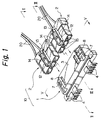
- FIGURE 1 shows a general perspective view of an embodiment of the connector 10 of the present invention.
- the connector 10 has four poles of terminals as an example.
- the connector is used to connect a main harness through a printed wiring base plate to various kinds of electrical devices.
- the connector 10 comprises a main connector body 1 and a mating connector body 2.
- the main connector body 1 has two sets of male terminals 4 which two poles in a casing 3 made of a resin. An end of each terminal 4 projects in the casing 3.
- FIGURE 5 shows a T-shaped cavity 5 in the casing 3 in connection with each set of terminals 4, which project in the cavity 5.
- a rib 6 is provided adjacent to the set of terminals 4 in each of the cavity 5.
- the rib 6 is integrally formed with the casing 3 made of the resin.
- FIGURE 6 shows a cross sectional view of the rib 6.
- the casing 3 is provided with a slot 7 in a top wall of each cavity 5.
- a slippage preventer 8 is formed in an end of the slot 7.
- Two mating connectors 2 are provided in connection with two sets of terminals 4 in the main connector body 1, respectively.
- Each mating connector 2 has two female terminals 9 with two poles.
- Each of two cords 20 is connected to each of the female terminals 9 in each of the mating connector body 2, as shown in FIGURE 2.
- the mating connector bodies are formed into the same cross section and have three cavities 15, respectively.
- the female terminal 9 is provided in the cavity 15 in connection with the male terminal 4 in the main connector body 1.
- the female terminal 9 is prevented from slipping out of the cavity 15 by a projection 11 formed therein.
- the mating connector body 2 is provided with another cavity 15 adjacent to the cavity 15 having the female terminal 9 (FIGURE 2), as shown in FIGURE 1.
- the last cavity 15 has no female terminals and receives the rib 6 in the main connector body 1 when the body 2 is properly coupled to the body 1 (see FIGURES 3 and 4).
- the mating connector body 2 is provided with a movable piece 12 on a top wall thereof.
- the movable piece 12 has a projection 13 on a middle portion thereof.
- the movable piece 12 engages with a vertical groove in the T-shaped cavity 5 in the main connector body 1 (see FIGURE 5) to guide the mating connector body 2 in the cavity 5.
- the projection 13 on the movable piece 12 engages with the slippage preventer 8 formed in the end of the slot 7 to lock the body 2 in the main body 1. If the mating connector body 2 should be disconnected from the main connector body 1, the projection 13 is disengaged from the slippage preventer 8 by pushing down and forward a rear end of the movable piece 12. Consequently, the body 2 can be readily drawn out of the main body 1.
- the mating connector body 2 is inserted into a wrong cavity 5, for example, if the body 2 to be inserted into the left side cavity 5 in FIGURE 5 is inserted into the right side cavity 5 by mistake, the mating connector body 2 cannot be completely inserted into the cavity 5 since the female terminal 9 in the body 2 abuts on the rib 6 in the cavity 5. Accordingly, the connector 10 can prevent the mating connector body 2 from being inserted into the wrong cavity in the main connector body 1.
- the male terminals 4 have two sets of two poles in the above embodiment, it will be apparent to a skilled person in the art that the present invention can be applied to the terminals having three sets of three poles.
- electrical connection can be obtained between the proper terminals, and ribs are provided in the vacant cavity in the main connector body to prevent the mating connector body from being inserted into the vacant cavity.
- the mating connector bodies can be formed into the same shape without providing different ribs thus being able to be produced at relatively low cost.
Landscapes
- Details Of Connecting Devices For Male And Female Coupling (AREA)
- Connector Housings Or Holding Contact Members (AREA)
Abstract
Description
- This invention relates to a connector used for an electrical connection in various kinds of electrical wiring.
- Various kinds of connectors are used in electrical wiring, in particular, various kinds of electrical devices for a motorcar. There are known connectors in which a housing having many terminals with many sets of poles receives a mating connector body having many terminals or in which a housing having many terminals receives many mating connector bodies each having a set or sets of terminals with a set or sets of poles.
- In the former connector out of the above prior connectors, a large force is required for coupling the terminals, since the terminals in the mating connector body must be connected to the terminals in the housing at the same time. As the terminals having many poles must be disposed in a housing, the housing becomes bulky and it is difficult to connect all the terminals with an even force thus resulting in wrenching of the terminals.
- In the latter connector, if all the mating connector bodies are formed into the same shape, the mating connector bodies will be improperly coupled to the housing. In order to prevent improper coupling, mating connector bodies are provided with ribs disposed in different positions in the bodies. However, this requires mating connector bodies to have different shapes and plural parts.
- An object of the present invention is to provide a connector which comprises a main connector body and a plurality of mating connector bodies, the main connector body being provided with ribs in different positions in connection with the mating connector bodies to prevent improper coupling, and the mating connector bodies being formed into the same shape to be made at a lower cost.
- In order to accomplish the above object, the connector in accordance with the present invention comprises a main connector body having a plurality of sets of male terminals in a casing, and a plurality of mating connector bodies having a set of female terminals connected to each set of divided conductor circuits. Each of the mating connector bodies is coupled to a respective coupling space in the main connector body. Sets of male terminals are provided in coupling spaces in the main connector body to be connection with sets of divided conductor circuits. The main connector body is provided with ribs adjacent to sets of male terminals in the coupling spaces. Each of the mating connector bodies is provided with a vacant cavity adjacent to the female terminals in connection with the rib. Each rib is disposed in a different position in each of the coupling spaces so that the rib is opposed to the vacant cavity in each of the mating connector bodies.
- The connector in accordance with the present invention provides an electrical connection when the mating connector bodies are properly coupled to the main connector body.
- If the mating connector body is inserted into a wrong coupling space in the main connector body by mistake, the rib in the coupling space prevents the female terminals in the mating connector body from being inserted into the space.
- FIGURE 1 is an exploded perspective view of an embodiment of a connector in accordance with the present invention;
- FIGURE 2 is a cross sectional view taken along a line II-II in FIGURE 1, which shows a position for inserting terminals;
- FIGURE 3 is a cross sectional view taken along a line III-III in FIGURE 1, which shows a position with no terminals;
- FIGURE 4 is a cross sectional view similar to FIGURE 3, which shows a position of the connector completely coupled;
- FIGURE 5 is a front view of a main connector body taken along a line V-V in FIGURE 1; and FIGURE 6 is a cross sectional view taken along a line VI-VI in FIGURE 5.
- Referring now to FIGURES 1 to 6, an embodiment of a
connector 10 in accordance with the present invention will be explained below. - FIGURE 1 shows a general perspective view of an embodiment of the
connector 10 of the present invention. Theconnector 10 has four poles of terminals as an example. For instance, in an electrical wiring for a motorcar, the connector is used to connect a main harness through a printed wiring base plate to various kinds of electrical devices. - The
connector 10 comprises amain connector body 1 and amating connector body 2. Themain connector body 1 has two sets ofmale terminals 4 which two poles in acasing 3 made of a resin. An end of eachterminal 4 projects in thecasing 3. - As shown in FIGURE 5, a T-
shaped cavity 5 is formed in thecasing 3 in connection with each set ofterminals 4, which project in thecavity 5. Arib 6 is provided adjacent to the set ofterminals 4 in each of thecavity 5. Therib 6 is integrally formed with thecasing 3 made of the resin. FIGURE 6 shows a cross sectional view of therib 6. Also, as shown in FIGURE 1, thecasing 3 is provided with aslot 7 in a top wall of eachcavity 5. Aslippage preventer 8 is formed in an end of theslot 7. - Two
mating connectors 2 are provided in connection with two sets ofterminals 4 in themain connector body 1, respectively. Eachmating connector 2 has twofemale terminals 9 with two poles. Each of twocords 20 is connected to each of thefemale terminals 9 in each of themating connector body 2, as shown in FIGURE 2. The mating connector bodies are formed into the same cross section and have threecavities 15, respectively. - The
female terminal 9 is provided in thecavity 15 in connection with themale terminal 4 in themain connector body 1. Thefemale terminal 9 is prevented from slipping out of thecavity 15 by aprojection 11 formed therein. When themating connector body 2 is inserted into thecavity 5 in themain connector body 1 as shown in FIGURE 2, themale terminal 4 is inserted into thefemale terminal 9 to make an electrical connection. - Further, the
mating connector body 2 is provided with anothercavity 15 adjacent to thecavity 15 having the female terminal 9 (FIGURE 2), as shown in FIGURE 1. Thus, there are three cavities in thebody 2. Thelast cavity 15 has no female terminals and receives therib 6 in themain connector body 1 when thebody 2 is properly coupled to the body 1 (see FIGURES 3 and 4). - The
mating connector body 2 is provided with amovable piece 12 on a top wall thereof. Themovable piece 12 has aprojection 13 on a middle portion thereof. When themating connector body 2 is inserted into themain connector body 1, themovable piece 12 engages with a vertical groove in the T-shaped cavity 5 in the main connector body 1 (see FIGURE 5) to guide themating connector body 2 in thecavity 5. When thebody 2 is moved to the complete coupling position in themain body 1, theprojection 13 on themovable piece 12 engages with theslippage preventer 8 formed in the end of theslot 7 to lock thebody 2 in themain body 1. If themating connector body 2 should be disconnected from themain connector body 1, theprojection 13 is disengaged from theslippage preventer 8 by pushing down and forward a rear end of themovable piece 12. Consequently, thebody 2 can be readily drawn out of themain body 1. - In the
connector 10 thus constructed above, when themating connector body 2 is coupled to themain connector body 1 as shown in FIGURE 2, theterminals mating connector body 2 is inserted into theproper cavity 5 in the correspondingmain connector body 1. - If the
mating connector body 2 is inserted into awrong cavity 5, for example, if thebody 2 to be inserted into theleft side cavity 5 in FIGURE 5 is inserted into theright side cavity 5 by mistake, themating connector body 2 cannot be completely inserted into thecavity 5 since thefemale terminal 9 in thebody 2 abuts on therib 6 in thecavity 5. Accordingly, theconnector 10 can prevent themating connector body 2 from being inserted into the wrong cavity in themain connector body 1. - Although the
male terminals 4 have two sets of two poles in the above embodiment, it will be apparent to a skilled person in the art that the present invention can be applied to the terminals having three sets of three poles. - In the connector in accordance with the present invention, electrical connection can be obtained between the proper terminals, and ribs are provided in the vacant cavity in the main connector body to prevent the mating connector body from being inserted into the vacant cavity. The mating connector bodies can be formed into the same shape without providing different ribs thus being able to be produced at relatively low cost.
Claims (1)
- A connector comprising:
a main connector body having a plurality of sets of male terminals in a casing; and
a plurality of mating connector bodies having a set of female terminals connected to sets of divided conductor circuits, each of said mating connector bodies being coupled to coupling spaces in said main connector body;
each set of said male terminals being provided in each coupling space in said main connector body in connection with said sets of said divided conductor circuits;
said main connector body being provided with ribs adjacent to each set of said male terminals in each coupling space;
each of said mating connector bodies being provided with a vacant cavity adjacent to said female terminals in connection with said rib;
each rib being disposed in a different position in each of said coupling spaces so that the rib is opposed to the vacant cavity in each mating connector body.
Applications Claiming Priority (2)
| Application Number | Priority Date | Filing Date | Title |
|---|---|---|---|
| JP3193165A JP2995934B2 (en) | 1991-08-01 | 1991-08-01 | Connector |
| JP193165/91 | 1991-08-01 |
Publications (3)
| Publication Number | Publication Date |
|---|---|
| EP0526053A2 true EP0526053A2 (en) | 1993-02-03 |
| EP0526053A3 EP0526053A3 (en) | 1993-06-23 |
| EP0526053B1 EP0526053B1 (en) | 1995-06-28 |
Family
ID=16303377
Family Applications (1)
| Application Number | Title | Priority Date | Filing Date |
|---|---|---|---|
| EP92306546A Expired - Lifetime EP0526053B1 (en) | 1991-08-01 | 1992-07-16 | Connector |
Country Status (4)
| Country | Link |
|---|---|
| US (1) | US5254018A (en) |
| EP (1) | EP0526053B1 (en) |
| JP (1) | JP2995934B2 (en) |
| DE (1) | DE69203171T2 (en) |
Cited By (3)
| Publication number | Priority date | Publication date | Assignee | Title |
|---|---|---|---|---|
| EP0938161A3 (en) * | 1998-02-24 | 2001-07-11 | Mecanismos Auxiliares Industriales S.A. M.A.I.S.A. | Improved module carrier for two modules |
| EP1229612A3 (en) * | 2001-02-02 | 2003-12-10 | Molex Incorporated | Keying system for electrical connector assemblies |
| WO2014063305A1 (en) * | 2012-10-23 | 2014-05-01 | Abb Technology Ltd | Control system with multiple terminal boards and method for connecting multiple terminal boards |
Families Citing this family (12)
| Publication number | Priority date | Publication date | Assignee | Title |
|---|---|---|---|---|
| SG43082A1 (en) * | 1992-12-02 | 1997-10-17 | Molex Inc | Plug and socket electrical connector system |
| GB9306881D0 (en) * | 1993-04-01 | 1993-05-26 | Strix Ltd | Electrical coupling |
| US5830001A (en) * | 1995-03-31 | 1998-11-03 | Japan Aviation Electronics Industry, Limited | Connector capable of reliably locking a plug connector to a receptacle connector |
| WO1997018602A1 (en) * | 1995-11-13 | 1997-05-22 | Intel Corporation | A dual-in-line universal serial bus connector |
| US5902155A (en) * | 1997-08-28 | 1999-05-11 | Molex Incorporated | Electrical connector assembly |
| USD425864S (en) * | 1998-04-14 | 2000-05-30 | Tommy Fristedt | Connecting plug |
| JP3248484B2 (en) | 1998-04-28 | 2002-01-21 | 住友電装株式会社 | Connector molding die |
| DE69918365T2 (en) * | 1998-04-28 | 2005-07-14 | Sumitomo Wiring Systems, Ltd., Yokkaichi | Connector pair and connector set |
| DE19950084C1 (en) * | 1999-10-18 | 2001-08-16 | Rema Lipprandt Gmbh Co Kg | Circuit board high current connector |
| US20020013080A1 (en) | 1999-11-23 | 2002-01-31 | Joseph Howard Gladd | Environmentally proctected bussed electrical center |
| JP2002298991A (en) * | 2001-03-30 | 2002-10-11 | Mitsumi Electric Co Ltd | connector |
| KR100476929B1 (en) * | 2002-09-03 | 2005-03-16 | 삼성전자주식회사 | USB system having card type USb interface connector |
Family Cites Families (8)
| Publication number | Priority date | Publication date | Assignee | Title |
|---|---|---|---|---|
| DE3673391D1 (en) * | 1986-03-05 | 1990-09-13 | Weidmueller C A Gmbh Co | MULTIPOLE CONNECTOR. |
| EP0235339B1 (en) * | 1986-03-05 | 1990-09-05 | C.A. Weidmüller GmbH & Co. | Multipole electrical connector |
| GB2193051A (en) * | 1986-07-22 | 1988-01-27 | Messerschmitt Boelkow Blohm | A coding element for a multi- terminal electrical connector |
| DE3738900A1 (en) * | 1987-11-17 | 1989-05-24 | Weidmueller C A Gmbh Co | MULTIPOLE CONNECTOR WITH CODING ELEMENTS |
| DE3807645C2 (en) * | 1988-03-09 | 1996-08-01 | Nicolay Gmbh | Connector system for electrical conductors |
| US4936943A (en) * | 1988-06-16 | 1990-06-26 | Continental Can Company, Inc. | Quick detach assembly for a sealing head |
| DE3911622A1 (en) * | 1989-04-08 | 1990-10-11 | Grundig Emv | DIVISIBLE MULTIPOLE CONNECTOR |
| US4986769A (en) * | 1989-11-16 | 1991-01-22 | Amp Incorporated | Polarization and keying mechanism |
-
1991
- 1991-08-01 JP JP3193165A patent/JP2995934B2/en not_active Expired - Lifetime
-
1992
- 1992-07-16 US US07/913,698 patent/US5254018A/en not_active Expired - Lifetime
- 1992-07-16 DE DE69203171T patent/DE69203171T2/en not_active Expired - Fee Related
- 1992-07-16 EP EP92306546A patent/EP0526053B1/en not_active Expired - Lifetime
Cited By (3)
| Publication number | Priority date | Publication date | Assignee | Title |
|---|---|---|---|---|
| EP0938161A3 (en) * | 1998-02-24 | 2001-07-11 | Mecanismos Auxiliares Industriales S.A. M.A.I.S.A. | Improved module carrier for two modules |
| EP1229612A3 (en) * | 2001-02-02 | 2003-12-10 | Molex Incorporated | Keying system for electrical connector assemblies |
| WO2014063305A1 (en) * | 2012-10-23 | 2014-05-01 | Abb Technology Ltd | Control system with multiple terminal boards and method for connecting multiple terminal boards |
Also Published As
| Publication number | Publication date |
|---|---|
| EP0526053A3 (en) | 1993-06-23 |
| JPH0541257A (en) | 1993-02-19 |
| EP0526053B1 (en) | 1995-06-28 |
| DE69203171D1 (en) | 1995-08-03 |
| US5254018A (en) | 1993-10-19 |
| DE69203171T2 (en) | 1995-11-09 |
| JP2995934B2 (en) | 1999-12-27 |
Similar Documents
| Publication | Publication Date | Title |
|---|---|---|
| EP0526053B1 (en) | Connector | |
| JP3043360B2 (en) | Connector structure having encoding means | |
| US5685737A (en) | Electrical connector having a visual indicator | |
| US5443403A (en) | Composite electrical connector assembly with snap-in housing | |
| US5161985A (en) | Board to board interconnect | |
| US4336418A (en) | Laminated junction box module and laminated plug-in accessory modules selectively usable therewith | |
| US6994595B2 (en) | Finger proof, keyed power connector and methods thereof | |
| JP3145271B2 (en) | Low insertion force connector | |
| US5403204A (en) | Joint connector | |
| EP0606903B1 (en) | Connector | |
| EP0310381A2 (en) | Components having means for keyed interconnectability | |
| EP0227288A2 (en) | Electrical connector with connector position assurance/assist device | |
| EP0038607A2 (en) | Modular connector housing | |
| EP0658956A1 (en) | Low connector force electrical connector system | |
| EP0578180A1 (en) | Configurable coded electrical plug and socket | |
| US5033980A (en) | Electrical connector with a double locking structure for terminals | |
| GB2188497A (en) | Electrical connector | |
| US3605070A (en) | Electrical connector | |
| AU2009201437A1 (en) | Installation couplers | |
| US5173059A (en) | Lock mechanism of inner lock type for electrical connector | |
| US6382842B1 (en) | Plug-in optical connector with wrong plugging prevention key | |
| US4239323A (en) | Circuit board keying arrangement | |
| US4838807A (en) | Electrical connector latching mechanism | |
| US7063574B2 (en) | Installation coupler | |
| EP4465456A1 (en) | Keyed electric connector |
Legal Events
| Date | Code | Title | Description |
|---|---|---|---|
| PUAI | Public reference made under article 153(3) epc to a published international application that has entered the european phase |
Free format text: ORIGINAL CODE: 0009012 |
|
| 17P | Request for examination filed |
Effective date: 19920803 |
|
| AK | Designated contracting states |
Kind code of ref document: A2 Designated state(s): DE GB |
|
| PUAL | Search report despatched |
Free format text: ORIGINAL CODE: 0009013 |
|
| AK | Designated contracting states |
Kind code of ref document: A3 Designated state(s): DE GB |
|
| 17Q | First examination report despatched |
Effective date: 19941019 |
|
| GRAA | (expected) grant |
Free format text: ORIGINAL CODE: 0009210 |
|
| AK | Designated contracting states |
Kind code of ref document: B1 Designated state(s): DE GB |
|
| REF | Corresponds to: |
Ref document number: 69203171 Country of ref document: DE Date of ref document: 19950803 |
|
| PLBE | No opposition filed within time limit |
Free format text: ORIGINAL CODE: 0009261 |
|
| STAA | Information on the status of an ep patent application or granted ep patent |
Free format text: STATUS: NO OPPOSITION FILED WITHIN TIME LIMIT |
|
| 26N | No opposition filed | ||
| PGFP | Annual fee paid to national office [announced via postgrant information from national office to epo] |
Ref country code: DE Payment date: 20010709 Year of fee payment: 10 |
|
| REG | Reference to a national code |
Ref country code: GB Ref legal event code: IF02 |
|
| PGFP | Annual fee paid to national office [announced via postgrant information from national office to epo] |
Ref country code: GB Payment date: 20020710 Year of fee payment: 11 |
|
| PG25 | Lapsed in a contracting state [announced via postgrant information from national office to epo] |
Ref country code: DE Free format text: LAPSE BECAUSE OF NON-PAYMENT OF DUE FEES Effective date: 20030201 |
|
| PG25 | Lapsed in a contracting state [announced via postgrant information from national office to epo] |
Ref country code: GB Free format text: LAPSE BECAUSE OF NON-PAYMENT OF DUE FEES Effective date: 20030716 |
|
| GBPC | Gb: european patent ceased through non-payment of renewal fee |
Effective date: 20030716 |