EP0525668B1 - Vehicle internal combustion engine exhaust system - Google Patents
Vehicle internal combustion engine exhaust system Download PDFInfo
- Publication number
- EP0525668B1 EP0525668B1 EP92112686A EP92112686A EP0525668B1 EP 0525668 B1 EP0525668 B1 EP 0525668B1 EP 92112686 A EP92112686 A EP 92112686A EP 92112686 A EP92112686 A EP 92112686A EP 0525668 B1 EP0525668 B1 EP 0525668B1
- Authority
- EP
- European Patent Office
- Prior art keywords
- exhaust
- engine
- silencer
- exhaust system
- fact
- Prior art date
- Legal status (The legal status is an assumption and is not a legal conclusion. Google has not performed a legal analysis and makes no representation as to the accuracy of the status listed.)
- Expired - Lifetime
Links
Images


Classifications
-
- F—MECHANICAL ENGINEERING; LIGHTING; HEATING; WEAPONS; BLASTING
- F01—MACHINES OR ENGINES IN GENERAL; ENGINE PLANTS IN GENERAL; STEAM ENGINES
- F01N—GAS-FLOW SILENCERS OR EXHAUST APPARATUS FOR MACHINES OR ENGINES IN GENERAL; GAS-FLOW SILENCERS OR EXHAUST APPARATUS FOR INTERNAL-COMBUSTION ENGINES
- F01N13/00—Exhaust or silencing apparatus characterised by constructional features
- F01N13/04—Exhaust or silencing apparatus characterised by constructional features having two or more silencers in parallel, e.g. having interconnections for multi-cylinder engines
-
- F—MECHANICAL ENGINEERING; LIGHTING; HEATING; WEAPONS; BLASTING
- F01—MACHINES OR ENGINES IN GENERAL; ENGINE PLANTS IN GENERAL; STEAM ENGINES
- F01N—GAS-FLOW SILENCERS OR EXHAUST APPARATUS FOR MACHINES OR ENGINES IN GENERAL; GAS-FLOW SILENCERS OR EXHAUST APPARATUS FOR INTERNAL-COMBUSTION ENGINES
- F01N13/00—Exhaust or silencing apparatus characterised by constructional features
- F01N13/009—Exhaust or silencing apparatus characterised by constructional features having two or more separate purifying devices arranged in series
-
- F—MECHANICAL ENGINEERING; LIGHTING; HEATING; WEAPONS; BLASTING
- F01—MACHINES OR ENGINES IN GENERAL; ENGINE PLANTS IN GENERAL; STEAM ENGINES
- F01N—GAS-FLOW SILENCERS OR EXHAUST APPARATUS FOR MACHINES OR ENGINES IN GENERAL; GAS-FLOW SILENCERS OR EXHAUST APPARATUS FOR INTERNAL-COMBUSTION ENGINES
- F01N13/00—Exhaust or silencing apparatus characterised by constructional features
- F01N13/011—Exhaust or silencing apparatus characterised by constructional features having two or more purifying devices arranged in parallel
- F01N13/017—Exhaust or silencing apparatus characterised by constructional features having two or more purifying devices arranged in parallel the purifying devices are arranged in a single housing
-
- F—MECHANICAL ENGINEERING; LIGHTING; HEATING; WEAPONS; BLASTING
- F01—MACHINES OR ENGINES IN GENERAL; ENGINE PLANTS IN GENERAL; STEAM ENGINES
- F01N—GAS-FLOW SILENCERS OR EXHAUST APPARATUS FOR MACHINES OR ENGINES IN GENERAL; GAS-FLOW SILENCERS OR EXHAUST APPARATUS FOR INTERNAL-COMBUSTION ENGINES
- F01N3/00—Exhaust or silencing apparatus having means for purifying, rendering innocuous, or otherwise treating exhaust
- F01N3/08—Exhaust or silencing apparatus having means for purifying, rendering innocuous, or otherwise treating exhaust for rendering innocuous
- F01N3/10—Exhaust or silencing apparatus having means for purifying, rendering innocuous, or otherwise treating exhaust for rendering innocuous by thermal or catalytic conversion of noxious components of exhaust
- F01N3/18—Exhaust or silencing apparatus having means for purifying, rendering innocuous, or otherwise treating exhaust for rendering innocuous by thermal or catalytic conversion of noxious components of exhaust characterised by methods of operation; Control
- F01N3/20—Exhaust or silencing apparatus having means for purifying, rendering innocuous, or otherwise treating exhaust for rendering innocuous by thermal or catalytic conversion of noxious components of exhaust characterised by methods of operation; Control specially adapted for catalytic conversion
- F01N3/2006—Periodically heating or cooling catalytic reactors, e.g. at cold starting or overheating
-
- F—MECHANICAL ENGINEERING; LIGHTING; HEATING; WEAPONS; BLASTING
- F01—MACHINES OR ENGINES IN GENERAL; ENGINE PLANTS IN GENERAL; STEAM ENGINES
- F01N—GAS-FLOW SILENCERS OR EXHAUST APPARATUS FOR MACHINES OR ENGINES IN GENERAL; GAS-FLOW SILENCERS OR EXHAUST APPARATUS FOR INTERNAL-COMBUSTION ENGINES
- F01N3/00—Exhaust or silencing apparatus having means for purifying, rendering innocuous, or otherwise treating exhaust
- F01N3/08—Exhaust or silencing apparatus having means for purifying, rendering innocuous, or otherwise treating exhaust for rendering innocuous
- F01N3/10—Exhaust or silencing apparatus having means for purifying, rendering innocuous, or otherwise treating exhaust for rendering innocuous by thermal or catalytic conversion of noxious components of exhaust
- F01N3/18—Exhaust or silencing apparatus having means for purifying, rendering innocuous, or otherwise treating exhaust for rendering innocuous by thermal or catalytic conversion of noxious components of exhaust characterised by methods of operation; Control
- F01N3/20—Exhaust or silencing apparatus having means for purifying, rendering innocuous, or otherwise treating exhaust for rendering innocuous by thermal or catalytic conversion of noxious components of exhaust characterised by methods of operation; Control specially adapted for catalytic conversion
- F01N3/2053—By-passing catalytic reactors, e.g. to prevent overheating
-
- F—MECHANICAL ENGINEERING; LIGHTING; HEATING; WEAPONS; BLASTING
- F01—MACHINES OR ENGINES IN GENERAL; ENGINE PLANTS IN GENERAL; STEAM ENGINES
- F01N—GAS-FLOW SILENCERS OR EXHAUST APPARATUS FOR MACHINES OR ENGINES IN GENERAL; GAS-FLOW SILENCERS OR EXHAUST APPARATUS FOR INTERNAL-COMBUSTION ENGINES
- F01N3/00—Exhaust or silencing apparatus having means for purifying, rendering innocuous, or otherwise treating exhaust
- F01N3/08—Exhaust or silencing apparatus having means for purifying, rendering innocuous, or otherwise treating exhaust for rendering innocuous
- F01N3/10—Exhaust or silencing apparatus having means for purifying, rendering innocuous, or otherwise treating exhaust for rendering innocuous by thermal or catalytic conversion of noxious components of exhaust
- F01N3/24—Exhaust or silencing apparatus having means for purifying, rendering innocuous, or otherwise treating exhaust for rendering innocuous by thermal or catalytic conversion of noxious components of exhaust characterised by constructional aspects of converting apparatus
- F01N3/28—Construction of catalytic reactors
- F01N3/2882—Catalytic reactors combined or associated with other devices, e.g. exhaust silencers or other exhaust purification devices
-
- F—MECHANICAL ENGINEERING; LIGHTING; HEATING; WEAPONS; BLASTING
- F01—MACHINES OR ENGINES IN GENERAL; ENGINE PLANTS IN GENERAL; STEAM ENGINES
- F01N—GAS-FLOW SILENCERS OR EXHAUST APPARATUS FOR MACHINES OR ENGINES IN GENERAL; GAS-FLOW SILENCERS OR EXHAUST APPARATUS FOR INTERNAL-COMBUSTION ENGINES
- F01N3/00—Exhaust or silencing apparatus having means for purifying, rendering innocuous, or otherwise treating exhaust
- F01N3/08—Exhaust or silencing apparatus having means for purifying, rendering innocuous, or otherwise treating exhaust for rendering innocuous
- F01N3/10—Exhaust or silencing apparatus having means for purifying, rendering innocuous, or otherwise treating exhaust for rendering innocuous by thermal or catalytic conversion of noxious components of exhaust
- F01N3/24—Exhaust or silencing apparatus having means for purifying, rendering innocuous, or otherwise treating exhaust for rendering innocuous by thermal or catalytic conversion of noxious components of exhaust characterised by constructional aspects of converting apparatus
- F01N3/28—Construction of catalytic reactors
- F01N3/2882—Catalytic reactors combined or associated with other devices, e.g. exhaust silencers or other exhaust purification devices
- F01N3/2885—Catalytic reactors combined or associated with other devices, e.g. exhaust silencers or other exhaust purification devices with exhaust silencers in a single housing
-
- F—MECHANICAL ENGINEERING; LIGHTING; HEATING; WEAPONS; BLASTING
- F01—MACHINES OR ENGINES IN GENERAL; ENGINE PLANTS IN GENERAL; STEAM ENGINES
- F01N—GAS-FLOW SILENCERS OR EXHAUST APPARATUS FOR MACHINES OR ENGINES IN GENERAL; GAS-FLOW SILENCERS OR EXHAUST APPARATUS FOR INTERNAL-COMBUSTION ENGINES
- F01N2230/00—Combination of silencers and other devices
- F01N2230/04—Catalytic converters
-
- F—MECHANICAL ENGINEERING; LIGHTING; HEATING; WEAPONS; BLASTING
- F01—MACHINES OR ENGINES IN GENERAL; ENGINE PLANTS IN GENERAL; STEAM ENGINES
- F01N—GAS-FLOW SILENCERS OR EXHAUST APPARATUS FOR MACHINES OR ENGINES IN GENERAL; GAS-FLOW SILENCERS OR EXHAUST APPARATUS FOR INTERNAL-COMBUSTION ENGINES
- F01N2310/00—Selection of sound absorbing or insulating material
- F01N2310/02—Mineral wool, e.g. glass wool, rock wool, asbestos or the like
-
- F—MECHANICAL ENGINEERING; LIGHTING; HEATING; WEAPONS; BLASTING
- F01—MACHINES OR ENGINES IN GENERAL; ENGINE PLANTS IN GENERAL; STEAM ENGINES
- F01N—GAS-FLOW SILENCERS OR EXHAUST APPARATUS FOR MACHINES OR ENGINES IN GENERAL; GAS-FLOW SILENCERS OR EXHAUST APPARATUS FOR INTERNAL-COMBUSTION ENGINES
- F01N2310/00—Selection of sound absorbing or insulating material
- F01N2310/04—Metallic wool, e.g. steel wool, copper wool or the like
-
- F—MECHANICAL ENGINEERING; LIGHTING; HEATING; WEAPONS; BLASTING
- F01—MACHINES OR ENGINES IN GENERAL; ENGINE PLANTS IN GENERAL; STEAM ENGINES
- F01N—GAS-FLOW SILENCERS OR EXHAUST APPARATUS FOR MACHINES OR ENGINES IN GENERAL; GAS-FLOW SILENCERS OR EXHAUST APPARATUS FOR INTERNAL-COMBUSTION ENGINES
- F01N2410/00—By-passing, at least partially, exhaust from inlet to outlet of apparatus, to atmosphere or to other device
- F01N2410/10—By-passing, at least partially, exhaust from inlet to outlet of apparatus, to atmosphere or to other device for reducing flow resistance, e.g. to obtain more engine power
-
- F—MECHANICAL ENGINEERING; LIGHTING; HEATING; WEAPONS; BLASTING
- F01—MACHINES OR ENGINES IN GENERAL; ENGINE PLANTS IN GENERAL; STEAM ENGINES
- F01N—GAS-FLOW SILENCERS OR EXHAUST APPARATUS FOR MACHINES OR ENGINES IN GENERAL; GAS-FLOW SILENCERS OR EXHAUST APPARATUS FOR INTERNAL-COMBUSTION ENGINES
- F01N2470/00—Structure or shape of exhaust gas passages, pipes or tubes
- F01N2470/14—Plurality of outlet tubes, e.g. in parallel or with different length
-
- F—MECHANICAL ENGINEERING; LIGHTING; HEATING; WEAPONS; BLASTING
- F01—MACHINES OR ENGINES IN GENERAL; ENGINE PLANTS IN GENERAL; STEAM ENGINES
- F01N—GAS-FLOW SILENCERS OR EXHAUST APPARATUS FOR MACHINES OR ENGINES IN GENERAL; GAS-FLOW SILENCERS OR EXHAUST APPARATUS FOR INTERNAL-COMBUSTION ENGINES
- F01N2470/00—Structure or shape of exhaust gas passages, pipes or tubes
- F01N2470/16—Plurality of inlet tubes, e.g. discharging into different chambers
-
- F—MECHANICAL ENGINEERING; LIGHTING; HEATING; WEAPONS; BLASTING
- F01—MACHINES OR ENGINES IN GENERAL; ENGINE PLANTS IN GENERAL; STEAM ENGINES
- F01N—GAS-FLOW SILENCERS OR EXHAUST APPARATUS FOR MACHINES OR ENGINES IN GENERAL; GAS-FLOW SILENCERS OR EXHAUST APPARATUS FOR INTERNAL-COMBUSTION ENGINES
- F01N2470/00—Structure or shape of exhaust gas passages, pipes or tubes
- F01N2470/18—Structure or shape of exhaust gas passages, pipes or tubes the axis of inlet or outlet tubes being other than the longitudinal axis of apparatus
-
- Y—GENERAL TAGGING OF NEW TECHNOLOGICAL DEVELOPMENTS; GENERAL TAGGING OF CROSS-SECTIONAL TECHNOLOGIES SPANNING OVER SEVERAL SECTIONS OF THE IPC; TECHNICAL SUBJECTS COVERED BY FORMER USPC CROSS-REFERENCE ART COLLECTIONS [XRACs] AND DIGESTS
- Y02—TECHNOLOGIES OR APPLICATIONS FOR MITIGATION OR ADAPTATION AGAINST CLIMATE CHANGE
- Y02A—TECHNOLOGIES FOR ADAPTATION TO CLIMATE CHANGE
- Y02A50/00—TECHNOLOGIES FOR ADAPTATION TO CLIMATE CHANGE in human health protection, e.g. against extreme weather
- Y02A50/20—Air quality improvement or preservation, e.g. vehicle emission control or emission reduction by using catalytic converters
-
- Y—GENERAL TAGGING OF NEW TECHNOLOGICAL DEVELOPMENTS; GENERAL TAGGING OF CROSS-SECTIONAL TECHNOLOGIES SPANNING OVER SEVERAL SECTIONS OF THE IPC; TECHNICAL SUBJECTS COVERED BY FORMER USPC CROSS-REFERENCE ART COLLECTIONS [XRACs] AND DIGESTS
- Y02—TECHNOLOGIES OR APPLICATIONS FOR MITIGATION OR ADAPTATION AGAINST CLIMATE CHANGE
- Y02T—CLIMATE CHANGE MITIGATION TECHNOLOGIES RELATED TO TRANSPORTATION
- Y02T10/00—Road transport of goods or passengers
- Y02T10/10—Internal combustion engine [ICE] based vehicles
- Y02T10/12—Improving ICE efficiencies
Definitions
- the present invention relates to a vehicle internal combustion engine exhaust system.
- number 1 indicates an exhaust system for an internal combustion engine 2 (shown schematically in block form) of a known vehicle (not shown).
- Engine 2 is supplied with air and fuel via intake manifold 3, and discharges the burnt gases via exhaust manifold 4, which communicates with a first exhaust control unit 5 preferably consisting of two so-called “catalytic mufflers" 5a, 5b arranged parallel to each other along respective pipes 9, 10 to which manifold 4 is connected by two-way end 7. Downstream from unit 5, pipes 9 and 10 also present a silencer indicated as a whole by 8.
- pipes 9 and 10 provide for feeding the exhaust gas into respective silencers or sections 11 and 12 forming part of silencer 8 and having parallel inlets.
- Silencers 11 and 12 may consist of two physically separate devices, as in the non-limiting example shown, or simply form part of one device through which the exhaust gas is fed along different routes.
- Silencer 11 is a known interference type, e.g. consisting of a number of Helmholtz resonating chambers and which therefore requires no further description; while silencer 12 is a known so-called dissipative type substantially comprising a hollow cylindrical body 13 through which pipe 10 is fitted coaxially, and the end faces of which are connected in fluidtight manner to respective portions of pipe 10.
- Pipe 10 presents an end portion or outlet pipe 14 extending outwards of body 13, and, inside body 13, presents a number of equally-spaced radial through holes 15.
- Body 13 is filled with metal wool or any other agglomerate of fibrous high-temperature-resistant material.
- pipe 10 Upstream (in relation to the flow direction of the exhaust gas) from the point at which pipe 10 enters body 13, pipe 10 houses an on-off means consisting of a throttle valve 16 operated, via a connecting rod 17, by a pneumatic actuator 18 as described later on.
- Actuator 18 communicates with intake manifold 3 via a conduit 19 and a normally-closed solenoid valve 20 controlled by a known processing system 21 (described later on) for processing signals supplied respectively over electric lines 22, 23 and 24 and respectively indicating the vacuum inside intake manifold 3 and the speed and spark lead of engine 2.
- processing system 21 provides for comparing at least one of the above parameters - engine speed, throttle opening angle and the vacuum inside intake manifold 3 (i.e. the load of engine 2) - with respective predetermined values memorized in table form, and preferably provides for simultaneously processing all the above parameters for reconstructing in real time the actual instantaneous load curve of engine 2, which is compared with respective theoretical curves mapped in the ROM memory of system 21.
- This may be specifically designed to control silencer 8, or consist, for example, of the processing system on the vehicle electronic injection and/or ignition system.
- system 21 opens solenoid valve 20 so as to connect intake manifold 3 to actuator 18, and so operate actuator 18 as to open throttle valve 16. That is, when subjected to a vacuum, actuator 18, which is of known type, provides for moving connecting rod 17 and so rotating throttle valve 16, which may incidentally be a mushroom type as opposed to the throttle valve in the example shown.
- silencer 12 which, being a dissipative type, produces a smaller load loss than silencer 11, thus reducing the exhaust back pressure of engine 2 as compared with that produced when valve 16 is closed.
- outlet pipes 14 and 25 of silencers 12 and 11 are separate, whereas, in the Fig.3 variation, they are so connected that the exhaust gas flows out of silencer 8 along a single end pipe 26.
- Exhaust system 1 thus provides for optimum performance of engine 2 by enabling greater output at high engine speeds, while at the same time maintaining a more than acceptable degree of noise attenuation, by virtue of the sound waves requiring silencer or silencer section 11 being produced predominantly at engine speeds well below those corresponding to maximum output of the engine.
- the present invention provides for dynamically adapting the characteristics of silencer 8 to the operating conditions of engine 2, thus preventing output at high engine speed from being impaired solely for the purpose of attenuating noise at medium-low engine speeds, as with known exhaust systems.
- engine 2 presents two separate, opposed exhaust manifolds 4, each connected to a respective exhaust pipe 10 along which is provided a catalyst or known catalytic muffler 5. Downstream from catalysts 5, pipes 10 are connected to respective silencer sections 11, 11b of the same type, formed along different paths inside a transverse muffler 31 at the rear of the vehicle. Despite being separate (one for each manifold 4), the two silencer sections 11 (or 11b in the case of 1b) present the same construction.
- the exhaust paths of manifolds 4, defined by respective pipes 10 and connected accessories (catalysts 5 and silencer sections 11, 11b) are symmetrical, and so present the same exhaust back pressure as regards engine 2.
- system 1a also comprises a further exhaust pipe 9 located between and branch connected to pipes 10 by a T fitting 32. Downstream from fitting 32, provision is made for an on-off throttle valve 16a as on system 1, and controlled in the same way by a processing system 21 and a pneumatic actuator 18 (not shown). Downstream from valve 16a, pipe 9 presents a further catalyst 33 optimized internally for processing the exhaust gas of rich air-fuel mixtures, i.e. having a low dilution ratio. Downstream from catalyst 33, pipe 9 is also connected to muffler 31 and more specifically to silencer section 12 having a lower load loss and different noise damping characteristics as compared with sections 11. Valve 16a may be located, with no effect on operation, at any point along pipe 9, from fitting 32 to the inlet of muffler 31, and with catalyst 33 located indifferently up- or downstream from valve 16a.
- System 1b in Fig.5 also presents a central pipe 9 connected to pipes 10 and manifolds 4 by a T fitting 32, but with two identical valves 16b on respective pipes 10 as opposed to a single valve 16a on pipe 9.
- Pipes 10 also present respective rich mixture catalysts 33, while central pipe 9 presents a traditional catalyst 5.
- Valves 16a and 16b are so designed that, when actuator 18 (not shown) by which they are controlled is de-activated (i.e. under normal operating conditions of the engine), they present a small opening angle enabling the exhaust gas to flow partially from manifolds 4 into pipe 9 (Fig.4) or pipes 10 (Fig.5), thus heating and maintaining an efficient temperature of catalyst/s 33.
- valve 16a directs the exhaust gas predominantly along pipes 10 and through respective catalysts 5 and silencer sections 11 (Fig.4), whereas valves 16b direct it predominantly along central pipe 9 and through respective catalyst 5 and silencer section 12b.
- valve 16a which is controlled in exactly the same way as 16, is opened fully so as to enable the exhaust gas to flow freely along pipes 10 and central pipe 9.
- pipe 9 is connected to a silencer section 12 having a lower load loss as compared with sections 11, most of the exhaust gas will flow along pipe 9, which, together with catalyst 33 and silencer section 12, defines a lower back pressure exhaust route, i.e. along which the gas encounters least resistance.
- valves 16b are opened fully so that the exhaust gas flows predominantly along lateral pipes 10, by virtue of the latter being connected to silencer sections 11b having a lower exhaust back pressure as compared with 12b to which central pipe 9 is connected.
- the exhaust gas is directed predominantly along the exhaust route of least resistance, thus optimizing output of engine 2 at high engine speed, as in the case of system 1.
- the exhaust gas is directed predominantly to the catalyst/s 33 specifically designed for the type of gas produced under such conditions, thus providing for more effective processing than that achievable, at low engine speed, by feeding most of the gas through weak-mixture catalysts 5.
- the present invention also provides for more or less completely mixing the exhaust gas from manifolds 4, thus further reducing pollution at high engine speed, and ensuring a fine balance of the exhaust back pressures of the two manifolds 4.
Landscapes
- Engineering & Computer Science (AREA)
- Chemical & Material Sciences (AREA)
- Chemical Kinetics & Catalysis (AREA)
- Combustion & Propulsion (AREA)
- Mechanical Engineering (AREA)
- General Engineering & Computer Science (AREA)
- Health & Medical Sciences (AREA)
- Toxicology (AREA)
- Exhaust Silencers (AREA)
- Exhaust Gas After Treatment (AREA)
- Control Of Throttle Valves Provided In The Intake System Or In The Exhaust System (AREA)
Description
- The present invention relates to a vehicle internal combustion engine exhaust system.
- The performance of an internal combustion engine in terms of output and the manner in which this is supplied (i.e. the characteristic curve of the engine) is known to depend, not only on the engine itself, but also on the exhaust system, the characteristics of which in turn depend on the type and degree of noise attenuation required.
- At the design stage, therefore, a trade-off is invariably involved between the characteristics of the engine and the exhaust system, and which generally results in impaired performance of the engine, particularly at high speed, due to the conflicting exhaust system design features required for achieving given performance characteristics at both high and low engine speeds. On catalyzed engines of high-performance (so-called Grand Touring) vehicles, operation of the catalyst has also been found to be impaired at high engine speed, due to the fuel supply system supplying a "richer" air/fuel mixture, i.e. having a lower dilution coefficient.
- From US-A-5,014,817 it is known an exhaust system, according to the first part of
claim 1, wherein a plurality of different exhaust routes, each having different sound-deaden characteristics, may be selectively operated at different engine speeds. Such a solution, likewise that provided in JP-A-59-74325, helps to reach an optimal sound attenuation at different engine speeds without the engine power characteristics to be seriously impaired. However, they do not solve the problems described above relating to the composition of the air/fuel mixture. - It is an object of the present invention to provide an internal combustion engine exhaust system enabling optimum operation of the system as a function of an engine parameter determining engine load, such as engine speed, throttle valve angle, load.
- According to the present invention, there is provided a vehicle internal combustion engine exhaust system as defined in
Claim 1. - A preferred non-limiting embodiment of the present invention will be described by way of example with reference to the accompanying drawings, in which:
- Fig.1 shows, partly in block form, an exhaust system in accordance with the teachings of the present invention;
- Fig.2 shows a partially sectioned view of a detail in the Fig.1 system;
- Fia.3 shows a variation of the Fig.2 detail;
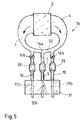
- Fig.s 4 and 5 show block diagrams of two preferred variations of the Fig.1 system.
- With reference to Figures 1 and 2,
number 1 indicates an exhaust system for an internal combustion engine 2 (shown schematically in block form) of a known vehicle (not shown). -
Engine 2 is supplied with air and fuel viaintake manifold 3, and discharges the burnt gases viaexhaust manifold 4, which communicates with a firstexhaust control unit 5 preferably consisting of two so-called "catalytic mufflers" 5a, 5b arranged parallel to each other alongrespective pipes manifold 4 is connected by two-way end 7. Downstream fromunit 5,pipes - As shown by way of example,
pipes sections silencer 8 and having parallel inlets.Silencers - Silencer 11 is a known interference type, e.g. consisting of a number of Helmholtz resonating chambers and which therefore requires no further description; while
silencer 12 is a known so-called dissipative type substantially comprising a hollowcylindrical body 13 through whichpipe 10 is fitted coaxially, and the end faces of which are connected in fluidtight manner to respective portions ofpipe 10. Pipe 10 presents an end portion oroutlet pipe 14 extending outwards ofbody 13, and, insidebody 13, presents a number of equally-spaced radial throughholes 15.Body 13 is filled with metal wool or any other agglomerate of fibrous high-temperature-resistant material. - Upstream (in relation to the flow direction of the exhaust gas) from the point at which
pipe 10 entersbody 13,pipe 10 houses an on-off means consisting of athrottle valve 16 operated, via a connectingrod 17, by apneumatic actuator 18 as described later on.Actuator 18 communicates withintake manifold 3 via aconduit 19 and a normally-closedsolenoid valve 20 controlled by a known processing system 21 (described later on) for processing signals supplied respectively overelectric lines intake manifold 3 and the speed and spark lead ofengine 2. - As explained later on,
processing system 21 provides for comparing at least one of the above parameters - engine speed, throttle opening angle and the vacuum inside intake manifold 3 (i.e. the load of engine 2) - with respective predetermined values memorized in table form, and preferably provides for simultaneously processing all the above parameters for reconstructing in real time the actual instantaneous load curve ofengine 2, which is compared with respective theoretical curves mapped in the ROM memory ofsystem 21. This may be specifically designed to controlsilencer 8, or consist, for example, of the processing system on the vehicle electronic injection and/or ignition system. - In actual use (Fig.s 1 and 2), as long as one or all of the parameters processed by
system 21 remain within predetermined values, i.e. indicating normal or at any rate less than maximum power operation ofengine 2, with no sharp acceleration in vehicle speed,solenoid valve 20 and, consequently,throttle valve 16 are maintained closed bysystem 21, and the exhaust gas flows throughmuffler 5 and silencer orsilencer section 11. - Conversely, upon the above parameters reaching predetermined threshold values, i.e. indicating maximum power demand of
engine 2, for example, for effecting a sharp acceleration in vehicle speed,system 21 openssolenoid valve 20 so as to connectintake manifold 3 toactuator 18, and so operateactuator 18 as to openthrottle valve 16. That is, when subjected to a vacuum,actuator 18, which is of known type, provides for moving connectingrod 17 and so rotatingthrottle valve 16, which may incidentally be a mushroom type as opposed to the throttle valve in the example shown. - When
throttle valve 16 is opened, the exhaust gas fromengine 2 flows partly throughsilencer 12, which, being a dissipative type, produces a smaller load loss thansilencer 11, thus reducing the exhaust back pressure ofengine 2 as compared with that produced whenvalve 16 is closed. By virtue of assisting exhaust as described above, the output ofengine 2 and consequently also instantaneous acceleration and response are thus improved as compared with known silencers. - In Fig.2,
outlet pipes silencers silencer 8 along asingle end pipe 26. -
Exhaust system 1 according to the present invention thus provides for optimum performance ofengine 2 by enabling greater output at high engine speeds, while at the same time maintaining a more than acceptable degree of noise attenuation, by virtue of the sound waves requiring silencer orsilencer section 11 being produced predominantly at engine speeds well below those corresponding to maximum output of the engine. In other words, the present invention provides for dynamically adapting the characteristics ofsilencer 8 to the operating conditions ofengine 2, thus preventing output at high engine speed from being impaired solely for the purpose of attenuating noise at medium-low engine speeds, as with known exhaust systems. - 1a and 1b in Fig.s 4 and 5 indicate two preferred variations of
exhaust system 1, any details of which similar to those already described are indicated using the same numbering system. More specifically,engine 2 presents two separate, opposedexhaust manifolds 4, each connected to arespective exhaust pipe 10 along which is provided a catalyst or knowncatalytic muffler 5. Downstream fromcatalysts 5,pipes 10 are connected torespective silencer sections transverse muffler 31 at the rear of the vehicle. Despite being separate (one for each manifold 4), the two silencer sections 11 (or 11b in the case of 1b) present the same construction. The exhaust paths ofmanifolds 4, defined byrespective pipes 10 and connected accessories (catalysts 5 andsilencer sections engine 2. - According to the present invention, system 1a also comprises a
further exhaust pipe 9 located between and branch connected topipes 10 by aT fitting 32. Downstream from fitting 32, provision is made for an on-off throttle valve 16a as onsystem 1, and controlled in the same way by aprocessing system 21 and a pneumatic actuator 18 (not shown). Downstream fromvalve 16a,pipe 9 presents afurther catalyst 33 optimized internally for processing the exhaust gas of rich air-fuel mixtures, i.e. having a low dilution ratio. Downstream fromcatalyst 33,pipe 9 is also connected tomuffler 31 and more specifically tosilencer section 12 having a lower load loss and different noise damping characteristics as compared withsections 11. Valve 16a may be located, with no effect on operation, at any point alongpipe 9, from fitting 32 to the inlet ofmuffler 31, and withcatalyst 33 located indifferently up- or downstream fromvalve 16a. -
System 1b in Fig.5, on the other hand, also presents acentral pipe 9 connected topipes 10 andmanifolds 4 by aT fitting 32, but with twoidentical valves 16b onrespective pipes 10 as opposed to asingle valve 16a onpipe 9.Pipes 10 also present respective rich mixture catalysts 33, whilecentral pipe 9 presents atraditional catalyst 5. - Valves 16a and 16b are so designed that, when actuator 18 (not shown) by which they are controlled is de-activated (i.e. under normal operating conditions of the engine), they present a small opening angle enabling the exhaust gas to flow partially from
manifolds 4 into pipe 9 (Fig.4) or pipes 10 (Fig.5), thus heating and maintaining an efficient temperature of catalyst/s 33. When partially open, in fact,valve 16a directs the exhaust gas predominantly alongpipes 10 and throughrespective catalysts 5 and silencer sections 11 (Fig.4), whereasvalves 16b direct it predominantly alongcentral pipe 9 and throughrespective catalyst 5 andsilencer section 12b. - With reference to Fig.4, when
engine 2 is operated at high speed, e.g. when accelerating sharply,valve 16a, which is controlled in exactly the same way as 16, is opened fully so as to enable the exhaust gas to flow freely alongpipes 10 andcentral pipe 9. Aspipe 9, however, is connected to asilencer section 12 having a lower load loss as compared withsections 11, most of the exhaust gas will flow alongpipe 9, which, together withcatalyst 33 andsilencer section 12, defines a lower back pressure exhaust route, i.e. along which the gas encounters least resistance. - Similarly (Fig.5), when
engine 2 is operated at high speed,valves 16b are opened fully so that the exhaust gas flows predominantly alonglateral pipes 10, by virtue of the latter being connected tosilencer sections 11b having a lower exhaust back pressure as compared with 12b to whichcentral pipe 9 is connected. In both the Fig.4 and 5 cases, therefore, under high-speed operating conditions of the engine, the exhaust gas is directed predominantly along the exhaust route of least resistance, thus optimizing output ofengine 2 at high engine speed, as in the case ofsystem 1. In addition, however, and by no means least importantly, at high engine speed, the exhaust gas is directed predominantly to the catalyst/s 33 specifically designed for the type of gas produced under such conditions, thus providing for more effective processing than that achievable, at low engine speed, by feeding most of the gas through weak-mixture catalysts 5. - In addition to the above advantages (greater output of
engine 2 and improved processing of the exhaust gas at high engine speed), the present invention also provides for more or less completely mixing the exhaust gas frommanifolds 4, thus further reducing pollution at high engine speed, and ensuring a fine balance of the exhaust back pressures of the twomanifolds 4.
Claims (7)
- A vehicle internal combustion engine exhaust system comprising, along the exhaust manifold (4) of said engine (2), at least two exhaust routes (9,12-10,11), and means (16, 16a, 16b, 18, 21) for selectively and predominantly directing the exhaust gas along one of said exhaust routes according to a variation in an engine parameter determining engine load, such as engine speed; said two exhaust routes (9,12-10,11) comprising: silencing means (11, 12, 11b, 12b) defined by at least two different silencers or silencer sections having parallel inlets; and at least two respective different catalysts (5, 33) for processing the exhaust gas at least one catalyst in each exhaust route arranged in parallel to a different catalyst in the respective other exhaust route ; characterized in that each one of said different catalysts is adapted specifically for processing different types of exhaust gases; and in that, in combination, a first one (11, 12b) of said silencers being so designed as to produce a greater load loss as compared with that of a second silencer (12, 11b).
- An exhaust system as claimed in Claim 1, characterized by the fact that it comprises, along said exhaust manifold (4), on-off means (16, 16a, 16b) provided for directing the exhaust gas towards one of said silencers (11, 12, 11b, 12b).
- An exhaust system as claimed in Claim 1 or 2, characterized by the fact that at least a first one (5) of said different catalysts is connected to said first silencer or silencer section (11, 12b) having the greater load loss; and at least a second one (33) of said different catalysts is optimized for processing the exhaust gas of rich air/fuel mixtures, and is connected to said second silencer or silencer section (12, 11b) having a lower load loss.
- An exhaust system as claimed in Claim 2 or 3, characterized by the fact that it comprises actuating means (18) for controlling said on-off means (16, 16a, 16b); and means (21) for determining at least one parameter consisting in engine speed, the opening angle of the throttle and the vacuum inside the intake manifold (3), or the load of said engine (2), and controlling said actuating means (18) as a function of said parameters.
- An exhaust system as claimed in one of the foregoing Claims from 2 to 4, characterized by the fact that said on-off means comprise valve means (16, 16a, 16b) for disabling or at least limiting flow of the exhaust gas to said second silencer (12, 11b).
- An exhaust system as claimed in Claim 2, characterized by the fact that said silencers (11, 12) present independent outlet pipes (14, 25).
- An exhaust system as claimed in Claim 2, characterized by the fact that said silencers (11, 12) present outlet pipes (14, 25) merging into a single end pipe (26).
Applications Claiming Priority (2)
| Application Number | Priority Date | Filing Date | Title |
|---|---|---|---|
| ITTO910593A IT1250822B (en) | 1991-07-26 | 1991-07-26 | COMBUSTION GAS DISCHARGE EQUIPMENT ASSOCIATED WITH AN ENDOTHERMAL MOTOR OF A VEHICLE. |
| ITTO910593 | 1991-07-26 |
Publications (2)
| Publication Number | Publication Date |
|---|---|
| EP0525668A1 EP0525668A1 (en) | 1993-02-03 |
| EP0525668B1 true EP0525668B1 (en) | 1996-01-31 |
Family
ID=11409522
Family Applications (1)
| Application Number | Title | Priority Date | Filing Date |
|---|---|---|---|
| EP92112686A Expired - Lifetime EP0525668B1 (en) | 1991-07-26 | 1992-07-24 | Vehicle internal combustion engine exhaust system |
Country Status (5)
| Country | Link |
|---|---|
| US (1) | US5301503A (en) |
| EP (1) | EP0525668B1 (en) |
| DE (1) | DE69207981T2 (en) |
| ES (1) | ES2082290T3 (en) |
| IT (1) | IT1250822B (en) |
Families Citing this family (12)
| Publication number | Priority date | Publication date | Assignee | Title |
|---|---|---|---|---|
| US5718718A (en) * | 1993-09-13 | 1998-02-17 | Angeion Corporation | Method and apparatus for polarity reversal of consecutive defibrillation countershocks having back biasing precharge pulses |
| DE4444098A1 (en) * | 1994-12-10 | 1996-06-13 | Opel Adam Ag | Internal combustion engine with two cylinder banks |
| GB2302707B (en) * | 1995-04-07 | 1998-12-09 | David Kent | Four-outlet exhaust systems for the full range of Lotus Esprit (RTM) vehicles to improve looks, improve sound and increase power |
| DE19520157A1 (en) * | 1995-06-01 | 1996-12-05 | Wolfgang Lenhardt | Motor vehicle exhaust silencer with choke flap |
| GB2313409A (en) * | 1996-05-21 | 1997-11-26 | Custom Chrome Limited | Adjustable exhaust silencer for vehicles |
| DE10231056A1 (en) * | 2002-07-10 | 2004-02-05 | J. Eberspächer GmbH & Co. KG | exhaust system |
| DE102005041692A1 (en) * | 2005-09-01 | 2007-03-15 | J. Eberspächer GmbH & Co. KG | Silencer for an exhaust system |
| TW200824781A (en) * | 2007-02-08 | 2008-06-16 | Rey-Chin Chu | Method and an apparatus for improving global warming and air pollution |
| DE602008006233D1 (en) | 2008-12-17 | 2011-05-26 | Magneti Marelli Spa | Exhaust system of an internal combustion engine |
| DE102011088150A1 (en) | 2011-12-09 | 2013-06-13 | Kess-Tech Gmbh | Silencer arrangement |
| DE102014209313A1 (en) * | 2014-05-16 | 2015-11-19 | Bayerische Motoren Werke Aktiengesellschaft | Exhaust system with variable exhaust gas paths |
| US20180223709A1 (en) * | 2017-02-06 | 2018-08-09 | GM Global Technology Operations LLC | Function based continuous exhaust valve control |
Family Cites Families (10)
| Publication number | Priority date | Publication date | Assignee | Title |
|---|---|---|---|---|
| US3282046A (en) * | 1964-06-11 | 1966-11-01 | Walker | Automatic treatment of selected portions of exhaust gases |
| DE2322057A1 (en) * | 1973-05-02 | 1974-11-21 | Porsche Ag | DEVICE FOR CATALYTIC AFTER-BURNING OF EXHAUST GASES OF A MULTICYLINDRICAL COMBUSTION MACHINE |
| JPS5610601A (en) * | 1979-07-05 | 1981-02-03 | Zatsukisu Arutooru | Overheated gas generating device |
| JPS5974325A (en) * | 1982-10-20 | 1984-04-26 | Yamaha Motor Co Ltd | Exhaust device for internal-combustion engine |
| FR2534969A1 (en) * | 1982-10-20 | 1984-04-27 | Florentz Bertrand | Device allowing the selection of the acoustic length of an exhaust system as a function of engine speed |
| JPS61200316A (en) * | 1985-03-01 | 1986-09-04 | Toyota Motor Corp | Exhaust gas purifying device for internal-combustion engine |
| IT206464Z2 (en) * | 1986-02-27 | 1987-08-10 | Alfa Romeo Spa | EXHAUST SYSTEM FOR A C.I. ENGINE |
| JPH01195908A (en) * | 1988-01-30 | 1989-08-07 | Mazda Motor Corp | Engine exhauster |
| JP2723948B2 (en) * | 1988-02-18 | 1998-03-09 | マツダ株式会社 | Engine control device |
| JPH0544503Y2 (en) * | 1988-07-29 | 1993-11-11 |
-
1991
- 1991-07-26 IT ITTO910593A patent/IT1250822B/en active IP Right Grant
-
1992
- 1992-07-24 US US07/917,899 patent/US5301503A/en not_active Expired - Lifetime
- 1992-07-24 DE DE69207981T patent/DE69207981T2/en not_active Expired - Lifetime
- 1992-07-24 EP EP92112686A patent/EP0525668B1/en not_active Expired - Lifetime
- 1992-07-24 ES ES92112686T patent/ES2082290T3/en not_active Expired - Lifetime
Also Published As
| Publication number | Publication date |
|---|---|
| IT1250822B (en) | 1995-04-21 |
| DE69207981T2 (en) | 1996-07-11 |
| ITTO910593A0 (en) | 1991-07-26 |
| US5301503A (en) | 1994-04-12 |
| EP0525668A1 (en) | 1993-02-03 |
| DE69207981D1 (en) | 1996-03-14 |
| ITTO910593A1 (en) | 1993-01-26 |
| ES2082290T3 (en) | 1996-03-16 |
Similar Documents
| Publication | Publication Date | Title |
|---|---|---|
| US6755279B2 (en) | Controllable muffler system for internal combustion engine | |
| US6349541B1 (en) | Exhaust silencer for an internal combustion engine and the method of operation | |
| US6732509B2 (en) | Engine acoustical system | |
| US5301503A (en) | Vehicle internal combustion engine exhaust system | |
| US9109483B2 (en) | Exhaust system for an internal combustion engine | |
| EP2199551B1 (en) | Exhaust system of an internal combustion engine | |
| US5072583A (en) | Exhaust system for internal combustion engines | |
| US4953352A (en) | Exhaust system | |
| US7121088B2 (en) | Automotive exhaust valve | |
| US6912843B2 (en) | Exhaust system for a multi-cylinder internal combustion engine | |
| US3983697A (en) | Exhaust gas cleaning system for internal combustion engines | |
| US4727829A (en) | Intake system for internal combustion engine | |
| US3888080A (en) | Air flow control valve | |
| US20010022174A1 (en) | Pressure control for supercharged engine | |
| JPH02157420A (en) | Exhaust device of internal combustion engine | |
| US4180975A (en) | Secondary air supply system using reed valves | |
| JPH0727028A (en) | Engine intake system | |
| JPH10122072A (en) | Variable intake pipe | |
| EP1445453A3 (en) | A silencer and a method of operating a vehicle | |
| CN113864089A (en) | An engine intake manifold, an intake system and a control method thereof | |
| JPH04121407A (en) | Exhaust device of engine | |
| GB2267842A (en) | Purifing exhaust gases | |
| JPH01170754A (en) | Muffling device for internal combustion engine | |
| JPH10246161A (en) | Automotive engine intake system | |
| JPH01195908A (en) | Engine exhauster |
Legal Events
| Date | Code | Title | Description |
|---|---|---|---|
| PUAI | Public reference made under article 153(3) epc to a published international application that has entered the european phase |
Free format text: ORIGINAL CODE: 0009012 |
|
| AK | Designated contracting states |
Kind code of ref document: A1 Designated state(s): DE ES FR GB SE |
|
| 17P | Request for examination filed |
Effective date: 19930729 |
|
| 17Q | First examination report despatched |
Effective date: 19941010 |
|
| GRAA | (expected) grant |
Free format text: ORIGINAL CODE: 0009210 |
|
| AK | Designated contracting states |
Kind code of ref document: B1 Designated state(s): DE ES FR GB SE |
|
| REF | Corresponds to: |
Ref document number: 69207981 Country of ref document: DE Date of ref document: 19960314 |
|
| REG | Reference to a national code |
Ref country code: ES Ref legal event code: FG2A Ref document number: 2082290 Country of ref document: ES Kind code of ref document: T3 |
|
| ET | Fr: translation filed | ||
| PLBE | No opposition filed within time limit |
Free format text: ORIGINAL CODE: 0009261 |
|
| STAA | Information on the status of an ep patent application or granted ep patent |
Free format text: STATUS: NO OPPOSITION FILED WITHIN TIME LIMIT |
|
| 26N | No opposition filed | ||
| REG | Reference to a national code |
Ref country code: GB Ref legal event code: IF02 |
|
| PGFP | Annual fee paid to national office [announced via postgrant information from national office to epo] |
Ref country code: FR Payment date: 20060621 Year of fee payment: 15 |
|
| PGFP | Annual fee paid to national office [announced via postgrant information from national office to epo] |
Ref country code: ES Payment date: 20060704 Year of fee payment: 15 |
|
| EUG | Se: european patent has lapsed | ||
| PG25 | Lapsed in a contracting state [announced via postgrant information from national office to epo] |
Ref country code: SE Free format text: LAPSE BECAUSE OF NON-PAYMENT OF DUE FEES Effective date: 20070725 |
|
| REG | Reference to a national code |
Ref country code: FR Ref legal event code: ST Effective date: 20080331 |
|
| PGFP | Annual fee paid to national office [announced via postgrant information from national office to epo] |
Ref country code: SE Payment date: 20060717 Year of fee payment: 15 |
|
| PG25 | Lapsed in a contracting state [announced via postgrant information from national office to epo] |
Ref country code: FR Free format text: LAPSE BECAUSE OF NON-PAYMENT OF DUE FEES Effective date: 20070731 |
|
| REG | Reference to a national code |
Ref country code: ES Ref legal event code: FD2A Effective date: 20070725 |
|
| PG25 | Lapsed in a contracting state [announced via postgrant information from national office to epo] |
Ref country code: ES Free format text: LAPSE BECAUSE OF NON-PAYMENT OF DUE FEES Effective date: 20070725 |
|
| PGFP | Annual fee paid to national office [announced via postgrant information from national office to epo] |
Ref country code: GB Payment date: 20110615 Year of fee payment: 20 |
|
| PGFP | Annual fee paid to national office [announced via postgrant information from national office to epo] |
Ref country code: DE Payment date: 20110620 Year of fee payment: 20 |
|
| REG | Reference to a national code |
Ref country code: DE Ref legal event code: R071 Ref document number: 69207981 Country of ref document: DE |
|
| REG | Reference to a national code |
Ref country code: DE Ref legal event code: R071 Ref document number: 69207981 Country of ref document: DE |
|
| REG | Reference to a national code |
Ref country code: GB Ref legal event code: PE20 Expiry date: 20120723 |
|
| PG25 | Lapsed in a contracting state [announced via postgrant information from national office to epo] |
Ref country code: GB Free format text: LAPSE BECAUSE OF EXPIRATION OF PROTECTION Effective date: 20120723 Ref country code: DE Free format text: LAPSE BECAUSE OF EXPIRATION OF PROTECTION Effective date: 20120725 |