EP0525410B1 - Mechanical face seals - Google Patents
Mechanical face seals Download PDFInfo
- Publication number
- EP0525410B1 EP0525410B1 EP92111039A EP92111039A EP0525410B1 EP 0525410 B1 EP0525410 B1 EP 0525410B1 EP 92111039 A EP92111039 A EP 92111039A EP 92111039 A EP92111039 A EP 92111039A EP 0525410 B1 EP0525410 B1 EP 0525410B1
- Authority
- EP
- European Patent Office
- Prior art keywords
- bellows unit
- seal
- seal according
- face member
- mechanical face
- Prior art date
- Legal status (The legal status is an assumption and is not a legal conclusion. Google has not performed a legal analysis and makes no representation as to the accuracy of the status listed.)
- Expired - Lifetime
Links
- 230000003014 reinforcing effect Effects 0.000 claims abstract description 17
- 239000000203 mixture Substances 0.000 claims abstract description 15
- 238000007789 sealing Methods 0.000 claims abstract description 12
- 230000015572 biosynthetic process Effects 0.000 claims description 14
- 239000000835 fiber Substances 0.000 claims description 9
- 230000002787 reinforcement Effects 0.000 claims description 6
- 238000000034 method Methods 0.000 claims description 5
- 230000006835 compression Effects 0.000 claims description 4
- 238000007906 compression Methods 0.000 claims description 4
- OKTJSMMVPCPJKN-UHFFFAOYSA-N Carbon Chemical compound [C] OKTJSMMVPCPJKN-UHFFFAOYSA-N 0.000 claims description 3
- 229920000459 Nitrile rubber Polymers 0.000 claims description 3
- 230000001154 acute effect Effects 0.000 claims description 3
- 239000004760 aramid Substances 0.000 claims description 3
- 229920003235 aromatic polyamide Polymers 0.000 claims description 3
- 229910052799 carbon Inorganic materials 0.000 claims description 3
- 238000001721 transfer moulding Methods 0.000 claims description 3
- 229920000181 Ethylene propylene rubber Polymers 0.000 claims description 2
- 238000001746 injection moulding Methods 0.000 claims description 2
- 238000000465 moulding Methods 0.000 claims description 2
- 229920003052 natural elastomer Polymers 0.000 claims description 2
- 229920001194 natural rubber Polymers 0.000 claims description 2
- 150000002825 nitriles Chemical class 0.000 claims description 2
- 229920003051 synthetic elastomer Polymers 0.000 claims description 2
- 239000005061 synthetic rubber Substances 0.000 claims description 2
- 238000005755 formation reaction Methods 0.000 description 12
- 229920001971 elastomer Polymers 0.000 description 5
- 239000005060 rubber Substances 0.000 description 5
- 239000000463 material Substances 0.000 description 3
- 239000004033 plastic Substances 0.000 description 3
- 229920003023 plastic Polymers 0.000 description 3
- 238000010276 construction Methods 0.000 description 2
- 239000002184 metal Substances 0.000 description 2
- 229920000742 Cotton Polymers 0.000 description 1
- 229910010293 ceramic material Inorganic materials 0.000 description 1
- 239000011152 fibreglass Substances 0.000 description 1
- 238000003780 insertion Methods 0.000 description 1
- 230000037431 insertion Effects 0.000 description 1
Images
Classifications
-
- F—MECHANICAL ENGINEERING; LIGHTING; HEATING; WEAPONS; BLASTING
- F16—ENGINEERING ELEMENTS AND UNITS; GENERAL MEASURES FOR PRODUCING AND MAINTAINING EFFECTIVE FUNCTIONING OF MACHINES OR INSTALLATIONS; THERMAL INSULATION IN GENERAL
- F16J—PISTONS; CYLINDERS; SEALINGS
- F16J15/00—Sealings
- F16J15/16—Sealings between relatively-moving surfaces
- F16J15/34—Sealings between relatively-moving surfaces with slip-ring pressed against a more or less radial face on one member
- F16J15/36—Sealings between relatively-moving surfaces with slip-ring pressed against a more or less radial face on one member connected by a diaphragm or bellow to the other member
-
- F—MECHANICAL ENGINEERING; LIGHTING; HEATING; WEAPONS; BLASTING
- F16—ENGINEERING ELEMENTS AND UNITS; GENERAL MEASURES FOR PRODUCING AND MAINTAINING EFFECTIVE FUNCTIONING OF MACHINES OR INSTALLATIONS; THERMAL INSULATION IN GENERAL
- F16J—PISTONS; CYLINDERS; SEALINGS
- F16J15/00—Sealings
- F16J15/16—Sealings between relatively-moving surfaces
- F16J15/18—Sealings between relatively-moving surfaces with stuffing-boxes for elastic or plastic packings
Definitions
- the present invention relates to mechanical face seals and in particular to mechanical face seals in which an elastomeric bellows unit provides secondary sealing between one seal face member and its associated component.
- one seal face member is mounted in fixed axial and rotational relationship and sealed with respect to one component while the other seal face member is mounted in fixed rotational relationship and sealed with respect to the other component, but is movable axially thereof.
- the axially movable seal face member is biased into engagement with the axially fixed seal face member to provide a seal between the engaging faces thereof.
- One method of sealing the axially movable seal face member with respect to its associated component is to use an elastomeric bellows unit, one end of which sealingly engages the seal face member and the other end sealingly engages the associated component.
- the bellows unit may be compressed and expanded axially in order to accommodate axial movement of the seal face member.
- WO-A-8907726 discloses a seal in which a reinforcing means made of resilient plastics material may be embedded in an elastomeric bellows unit, said reinforcing means serves to clamp the bellows unit into sealing engagement with the associated components and transmit torsional stresses therebetween, as well as providing axial loading of the seal face member into sealing engagement with the seat.
- resilient bushes are used to provide a seal between the axially movable seal face member and associated component, compression of the bush serving to axially load the seal face members into sealing engagement.
- Such bushes will however provide only low axial compliance and the axial load over the operating range will vary considerably.
- EP 0,226,845A discloses an elastomeric bellows seal with no separate spring means.
- the bellows unit of this seal is formed from unreinforced rubber having end portions which sealingly engage a shaft and seal face member, respectively.
- a relatively thin unsupported intermediate portion is arranged to buckle when the bellows unit is at its working length in order to apply an axial load urging the seal face member into engagement with a seat.
- the present invention provides a mechanical face seal with bellows unit which will provide the secondary seal between the axially movable seal face member and associated component and which also applies an axial load urging the seal face members into sealing engagement and is capable of withstanding pressure differentials of the order of 10 bar.
- a mechanical face seal provides a seal between a pair of relatively rotatable components comprising a first seal face member mounted in fixed rotational and axial relationship and sealed with respect to one component, and a second seal face member mounted in fixed rotational relationship but movable axially of the other component, an elastomeric bellows unit being sealed at one end to said other component and at the other end to said second seal face member, the second seal face member being permanently urged axially into sealing engagement with the first seal face member solely by means of compression of the elastomeric bellows unit, characterised in that the elastomeric bellows unit defines an axially compressible convoluted section comprising a pair of substantially axially extending portions, one axially extending portion being spaced radially of the other axially extending portion, the axially extending portions being interconnected by a radially extending portion, the radially extending portion being disposed at an acute angle to each axially extending portion, the
- the fibre reinforcement of the elastomeric bellows unit will increase the strength and stiffness of the bellows unit while maintaining adequate flexibility.
- Any suitable reinforcing fibre may be used although these will have to withstand the temperatures, typically 150°c to 180°c, to which they will be subjected during moulding of the bellows unit. Suitable materials include cotton and fibreglass, although stronger materials such as aramid or carbon fibres are preferred.
- the elastomeric composition may contain from 1% to 15% by volume or more preferably from 2% to 7% by volume, reinforcing fibre.
- the fibre length may be from 0.1 mm to 25 mm preferably predominantly from 0.1 mm to 6 mm.
- the bellows unit may be made of any suitable natural or synthetic rubber composition although nitrile or ethylene propylene rubbers are preferred.
- the bellows unit is preferably made using a transfer or injection moulding technique in which the rubber composition with fibre reinforcement is extruded axially into the mould, so that the fibres will be aligned to the required orientation.
- the bellows unit used in the present invention will have end formations for engagement of the seal face member and associated component respectively.
- the end formations are interconnected by an axially compressible convoluted section.
- the convoluted section is preferably of "Z" shape having a pair of substantially axially extending portions one connected to each of the end formations, the axially extending portions being interconnected by a radially extending portion disposed at an acute angle to the two axially extending portions.
- the angle between the radially extending portion and each axially extending portion of the convoluted section is from 50° to 70°, the angles being radiussed, particularly where radial clearance is limited, for example where the seal is located in a stuffing box such as those covered by ISO 3069. Where greater radial clearance is available larger angles could be used.
- Clamping means may be provided round the end formations of the bellows unit to compress these formations into engagement with the seal face member and associated component.
- the seal face member may be moulded from carbon or sintered ceramic material.
- corrugations may be provided in the end portion of the bellows unit engaging the seal face member in order to provide compliance therein.
- annular seal face member or seat 10 is located in a recess 12 in a housing 13, an elastomeric cup 11 being interposed therebetween to provide a seal.
- the seat 10 and elastomeric cup 11 are a press fit in the recess 12 so that they are fixed rotationally and axially with respect to the housing 13.
- the seat 10 surrounds a shaft 20 which is rotatable with respect to the housing 13.
- a second seal face member 21 is mounted upon the shaft 20, the seal face member 21 being secured to one end 26 of the bellows unit 25 the other end 27 of the bellows unit 25 being secured to the shaft 20.
- the bellows unit 25 which is illustrated in greater detail in Figure 2, is moulded from a nitrile rubber composition containing 3.4% by volume of aramid reinforcing fibres from 0.1 mm to 25 mm in length, at least 50% of the fibres being between 0.2 mm and 2 mm in length.
- the bellows unit 25 is moulded using a transfer moulding technique in which the rubber composition with fibre reinforcement is extruded axially into the mould, thereby aligning the fibres so that they are orientated axially of the mould.
- the rubber composition is then cured at 165°c.
- the bellows unit 25 has a reduced diameter tubular formation 30 at end 27, the inside diameter of the tubular portion 30 being an interference fit on the shaft 20.
- a circumferential recess 31 is provided on the external diameter of tubular portion 30 for a metal or plastic clamping ring 32, which will compress the rubber composition onto the shaft 20 so that torque may be transmitted between the shaft 20 and bellows unit 25.
- the tubular portion 30 has a radiussed lead-in portion 33 and angled portion 34 to facilitate insertion of the shaft 20.
- the opposite end 26 of the bellows unit 25 defines an enlarged diameter socket formation 35, for engagement of the external diameter of the seal face member 21.
- the socket formation 35 has a radially extending shoulder portion 36 which locates the seal face member 21 axially with respect to the bellows unit 25.
- Ribs 38 are provided on the internal diameter 37 of socket formation 35 to provide compliance, so that a seal will be produced with the seal face member 21, even if the engaging surface of the seal face member 21 is not machined to close tolerances.
- a circumferential groove 39 is provided in the external diameter of socket formation 35 for a metal or plastic clamping ring 40.
- the tubular formation 30 and socket formation 35 of the bellows unit 25 are interconnected by a convoluted section 45 of "Z" section.
- the convoluted section 45 has a pair of axially extending portions 46 and 47 interconnected by an intermediate radially extending portion 48.
- the intermediate portion 48 is disposed at 60° to each of the axially extending portions 46 and 47, the crowns 49 and 50 defined thereby being radiussed on both their internal and external surfaces.
- the convoluted section 45 is compressed so that the convolutions between portions 46 and 48 and portions 48 and 47 are substantially closed.
- the crown 49 abuts the rear face 51 of seal face member 21 to assist in supporting and maintaining location of face member 21 and bellows unit 25, to urge the seal face member 21 into sealing engagement with seat 10.
- the fibre reinforcement of the bellows unit 25 will improve the strength of the bellows unit 25 whilst maintaining adequate flexibility, so that sufficient loading may be maintained over the working life of the seal, without assistance from separate spring means.
- the fibre reinforcement will also improve the bellows capability to withstand pressure differentials across the seal. This improved performance is further enhanced by the substantially closed convolutions, which effectively reinforce one another when subjected to substantial pressure differentials, for example of the order of 10 bars.
- the seal disclosed above is also axially compact as compared with other forms of bellows seal.
- the end of the seal face member 21 defining a seal face 52 which engages face 53 of the seat 10 is of increased internal diameter, while the diameter at the opposite end 51 is a close clearance fit with the shaft 20.
- the seal face member 21 will thus be located concentrically by the shaft 20 while being free to move axially thereof. This will provide radial stability for the seal face member 21 which would otherwise be free to oscillate radially if only supported by the flexible bellows unit 25, this being an important criteria for operation at these design pressures.
- the seat 10 is located in a retaining ring 60 and is sealed with respect thereto by means of elastomeric cup 11.
- the retaining ring 60 is a press fit on the shaft 20 so as to be fixed rotatably with respect thereto and is located axially of the shaft 20 by abutment against a shoulder 61 thereon.
- the bellows unit 25 and seal face member 21 are located in a retaining ring 65 which is a press fit within a recess 66 in the housing 13, the bellows unit 25 sealingly engaging an inner cylindrical wall 67 of the retaining ring 65.
- the internal diameter of the seal face member 21 at the end remote from the sealing face 52 thereof being a close clearance fit with the inner wall 67 of the ring 65 to provide radial stability.
Landscapes
- Engineering & Computer Science (AREA)
- General Engineering & Computer Science (AREA)
- Mechanical Engineering (AREA)
- Mechanical Sealing (AREA)
- Encapsulation Of And Coatings For Semiconductor Or Solid State Devices (AREA)
- Sealing Devices (AREA)
Abstract
Description
- The present invention relates to mechanical face seals and in particular to mechanical face seals in which an elastomeric bellows unit provides secondary sealing between one seal face member and its associated component.
- In mechanial face seals for providing a seal between a pair of relatively rotatable components, one seal face member is mounted in fixed axial and rotational relationship and sealed with respect to one component while the other seal face member is mounted in fixed rotational relationship and sealed with respect to the other component, but is movable axially thereof. The axially movable seal face member is biased into engagement with the axially fixed seal face member to provide a seal between the engaging faces thereof.
- One method of sealing the axially movable seal face member with respect to its associated component is to use an elastomeric bellows unit, one end of which sealingly engages the seal face member and the other end sealingly engages the associated component. The bellows unit may be compressed and expanded axially in order to accommodate axial movement of the seal face member.
- Hitherto with seals of this construction in order to achieve sufficient axial compliance, the axial resilience of the bellows unit is low and separate spring means with associated retaining rings have had to be used to bias the seal face members into sealing engagement, for example as disclosed in GB 593,413 and GB 647,587.
- WO-A-8907726 discloses a seal in which a reinforcing means made of resilient plastics material may be embedded in an elastomeric bellows unit, said reinforcing means serves to clamp the bellows unit into sealing engagement with the associated components and transmit torsional stresses therebetween, as well as providing axial loading of the seal face member into sealing engagement with the seat.
- In another form of seal, for example as disclosed in GB 2,019,956A, resilient bushes are used to provide a seal between the axially movable seal face member and associated component, compression of the bush serving to axially load the seal face members into sealing engagement. Such bushes will however provide only low axial compliance and the axial load over the operating range will vary considerably.
- EP 0,226,845A discloses an elastomeric bellows seal with no separate spring means. The bellows unit of this seal is formed from unreinforced rubber having end portions which sealingly engage a shaft and seal face member, respectively. A relatively thin unsupported intermediate portion is arranged to buckle when the bellows unit is at its working length in order to apply an axial load urging the seal face member into engagement with a seat. With this bellows unit design, when subjected to a pressure differential, this will act on the bellows unit, either side and across the already highly stressed buckled intermediate portion thereof, further stressing this area so that even at relatively low pressure differentials the bellows unit is excessively stressed and liable to split. As a result bellows seals of this construction are limited to use with low pressure differentials up to of the order of 2 bar.
- The present invention provides a mechanical face seal with bellows unit which will provide the secondary seal between the axially movable seal face member and associated component and which also applies an axial load urging the seal face members into sealing engagement and is capable of withstanding pressure differentials of the order of 10 bar.
- According to one aspect of the present invention, a mechanical face seal provides a seal between a pair of relatively rotatable components comprising a first seal face member mounted in fixed rotational and axial relationship and sealed with respect to one component, and a second seal face member mounted in fixed rotational relationship but movable axially of the other component, an elastomeric bellows unit being sealed at one end to said other component and at the other end to said second seal face member, the second seal face member being permanently urged axially into sealing engagement with the first seal face member solely by means of compression of the elastomeric bellows unit, characterised in that the elastomeric bellows unit defines an axially compressible convoluted section comprising a pair of substantially axially extending portions, one axially extending portion being spaced radially of the other axially extending portion, the axially extending portions being interconnected by a radially extending portion, the radially extending portion being disposed at an acute angle to each axially extending portion, the bellows unit being formed from an elastomeric composition with reinforcing fibres embedded therein, the reinforcing fibres being orientated axially of the bellows unit, the bellows unit being axially compressed when at its working length.
- The fibre reinforcement of the elastomeric bellows unit will increase the strength and stiffness of the bellows unit while maintaining adequate flexibility. Any suitable reinforcing fibre may be used although these will have to withstand the temperatures, typically 150°c to 180°c, to which they will be subjected during moulding of the bellows unit. Suitable materials include cotton and fibreglass, although stronger materials such as aramid or carbon fibres are preferred. The elastomeric composition may contain from 1% to 15% by volume or more preferably from 2% to 7% by volume, reinforcing fibre. The fibre length may be from 0.1 mm to 25 mm preferably predominantly from 0.1 mm to 6 mm. The bellows unit may be made of any suitable natural or synthetic rubber composition although nitrile or ethylene propylene rubbers are preferred.
- The bellows unit is preferably made using a transfer or injection moulding technique in which the rubber composition with fibre reinforcement is extruded axially into the mould, so that the fibres will be aligned to the required orientation.
- The bellows unit used in the present invention will have end formations for engagement of the seal face member and associated component respectively. The end formations are interconnected by an axially compressible convoluted section. The convoluted section is preferably of "Z" shape having a pair of substantially axially extending portions one connected to each of the end formations, the axially extending portions being interconnected by a radially extending portion disposed at an acute angle to the two axially extending portions. Preferably the angle between the radially extending portion and each axially extending portion of the convoluted section is from 50° to 70°, the angles being radiussed, particularly where radial clearance is limited, for example where the seal is located in a stuffing box such as those covered by ISO 3069. Where greater radial clearance is available larger angles could be used.
- When at its working lengths the convoluted section is compressed so that the convolutions are substantially closed.
- Clamping means may be provided round the end formations of the bellows unit to compress these formations into engagement with the seal face member and associated component. The seal face member may be moulded from carbon or sintered ceramic material. In order to avoid the need to machine to close tolerances the face engaged by the bellows unit, corrugations may be provided in the end portion of the bellows unit engaging the seal face member in order to provide compliance therein.
- An embodiment of the invention is now described, by way of example only, with reference to the accompanying drawings in which:
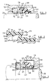
- Figure 1 illustrates in sectional elevation a seal in accordance with the present invention, at working length;
- Figure 2 illustrates in sectional elevation the bellows unit used in the seal illustrated in Figure 1, in its uncompressed condition; and
- Figure 3 illustrates in sectional elevation an alternative form of seal in accordance with the present invention.
- As illustrated in Figure 1, an annular seal face member or
seat 10 is located in arecess 12 in ahousing 13, anelastomeric cup 11 being interposed therebetween to provide a seal. Theseat 10 andelastomeric cup 11 are a press fit in therecess 12 so that they are fixed rotationally and axially with respect to thehousing 13. - The
seat 10 surrounds ashaft 20 which is rotatable with respect to thehousing 13. A secondseal face member 21 is mounted upon theshaft 20, theseal face member 21 being secured to oneend 26 of thebellows unit 25 theother end 27 of thebellows unit 25 being secured to theshaft 20. - The
bellows unit 25 which is illustrated in greater detail in Figure 2, is moulded from a nitrile rubber composition containing 3.4% by volume of aramid reinforcing fibres from 0.1 mm to 25 mm in length, at least 50% of the fibres being between 0.2 mm and 2 mm in length. Thebellows unit 25 is moulded using a transfer moulding technique in which the rubber composition with fibre reinforcement is extruded axially into the mould, thereby aligning the fibres so that they are orientated axially of the mould. The rubber composition is then cured at 165°c. - The
bellows unit 25 has a reduced diametertubular formation 30 atend 27, the inside diameter of thetubular portion 30 being an interference fit on theshaft 20. Acircumferential recess 31 is provided on the external diameter oftubular portion 30 for a metal orplastic clamping ring 32, which will compress the rubber composition onto theshaft 20 so that torque may be transmitted between theshaft 20 andbellows unit 25. Thetubular portion 30 has a radiussed lead-inportion 33 andangled portion 34 to facilitate insertion of theshaft 20. - The
opposite end 26 of thebellows unit 25 defines an enlargeddiameter socket formation 35, for engagement of the external diameter of theseal face member 21. Thesocket formation 35 has a radially extendingshoulder portion 36 which locates theseal face member 21 axially with respect to thebellows unit 25.Ribs 38 are provided on theinternal diameter 37 ofsocket formation 35 to provide compliance, so that a seal will be produced with theseal face member 21, even if the engaging surface of theseal face member 21 is not machined to close tolerances. Acircumferential groove 39 is provided in the external diameter ofsocket formation 35 for a metal orplastic clamping ring 40. - The
tubular formation 30 andsocket formation 35 of thebellows unit 25 are interconnected by a convolutedsection 45 of "Z" section. The convolutedsection 45 has a pair of axially extendingportions 46 and 47 interconnected by an intermediate radially extendingportion 48. Theintermediate portion 48 is disposed at 60° to each of the axially extendingportions 46 and 47, thecrowns - As illustrated in Figure 1, when the seal is assembled and the
bellows unit 25 is at its working length, the convolutedsection 45 is compressed so that the convolutions betweenportions portions 48 and 47 are substantially closed. In this position, thecrown 49 abuts therear face 51 ofseal face member 21 to assist in supporting and maintaining location offace member 21 and bellowsunit 25, to urge theseal face member 21 into sealing engagement withseat 10. The fibre reinforcement of thebellows unit 25 will improve the strength of thebellows unit 25 whilst maintaining adequate flexibility, so that sufficient loading may be maintained over the working life of the seal, without assistance from separate spring means. The fibre reinforcement will also improve the bellows capability to withstand pressure differentials across the seal. This improved performance is further enhanced by the substantially closed convolutions, which effectively reinforce one another when subjected to substantial pressure differentials, for example of the order of 10 bars. The seal disclosed above is also axially compact as compared with other forms of bellows seal. - The end of the
seal face member 21 defining aseal face 52 which engagesface 53 of theseat 10 is of increased internal diameter, while the diameter at theopposite end 51 is a close clearance fit with theshaft 20. Theseal face member 21 will thus be located concentrically by theshaft 20 while being free to move axially thereof. This will provide radial stability for theseal face member 21 which would otherwise be free to oscillate radially if only supported by theflexible bellows unit 25, this being an important criteria for operation at these design pressures. - In the embodiment illustrated in Figure 3, the
seat 10 is located in aretaining ring 60 and is sealed with respect thereto by means ofelastomeric cup 11. Theretaining ring 60 is a press fit on theshaft 20 so as to be fixed rotatably with respect thereto and is located axially of theshaft 20 by abutment against ashoulder 61 thereon. - The
bellows unit 25 andseal face member 21 are located in aretaining ring 65 which is a press fit within arecess 66 in thehousing 13, thebellows unit 25 sealingly engaging an innercylindrical wall 67 of theretaining ring 65. The internal diameter of theseal face member 21 at the end remote from the sealingface 52 thereof being a close clearance fit with theinner wall 67 of thering 65 to provide radial stability. - This embodiment of the seal functions in the same manner as that described with reference to Figures 1 and 2, the axially movable
seal face member 21 is however fixed rotationally while theseat 10 rotates with theshaft 20.
Claims (21)
- A mechanical face seal for providing a seal between a pair of relatively rotatable components (13,20) comprising a first seal face member (10) mounted in fixed rotational and axial relationship and sealed with respect to one component (13;20), and a second seal face member (21) mounted in fixed rotational relationship but movable axially of the other component (20;13), an elastomeric bellows unit (25) being sealed at one end to said other component (20;13) and at the other end to said second seal face member (21), the second seal face member (21) being permanently urged axially into sealing engagement with the first seal face member solely (10) by means of compression of the elastomeric bellows unit (25), characterised in that the elastomeric bellows unit (25) defines an axially compressible convoluted section (45) comprising a pair of substantially axially extending portions (46,47), one axially extending portion (46) being spaced radially of the other axially extending portion (47), the axially extending portions (46,47) being interconnected by a radially extending portion (48), the radially extending portion (48) being disposed at an acute angle to each axially extending portion (46,47), the bellows unit (25) being formed from an elastomeric composition with reinforcing fibres embedded therein, the reinforcing fibres being orientated axially of the bellows unit (25), the bellows unit (25) being axially compressed when at its working length.
- A mechanical face seal according to Claim 1 characterised in that one of the axially extending portions (26) of the bellows unit (25) defines an end formation (35) which sealingly engages the second seal face member (21) and the other axially extending portion (27) of the bellows unit (25) defines an end formation (30) which sealingly engages the associated component (20).
- A mechanical face seal according to Claim 1 or 2 characterised in that the radially extending portion (48) is inclined to the axially extending portions (46,47) at an angle of from 50° to 70°, when the bellows unit (25) is not in compression.
- A mechanical face seal according to any one of the preceding claims characterised in that the crowns (49,50) formed at the junction of the axially extending portions (46,47) and radially extending portion (48) are radiussed on their internal and external surfaces.
- A mechanical face seal according to any one of the preceding claims characterised in that the convoluted section (45) is compresssed so that the convolutions are substantially closed, when the bellows unit (25) is at its working length.
- A mechanical face seal according to Claim 5 characterised in that the crown (49) of one convolution abuts the rear face (51) of the second seal face member (21) when the bellows unit (25) is at its working length.
- A mechanical face seal according to any one of the preceding claims characterised in that the bellows unit (25) defines a tubular portion (30) at one end (27), for engagement about a cylindrical surface of the associated component (20;13) and a socket portion (35) adjacent the other end (26) for engagement of an outer cylindrical surface of the second seal face member (21).
- A mechanical face seal according to Claim 7 characterised in that the socket portion (35) is provided with a series of circumferential ribs (38) on its internal diameter (37), the ribs (38) being compressed to form a seal with the second seal face member (21).
- A mechanical face seal according to any one of the preceding claims characterised in that the bellows unit (25) is formed from a natural or synthetic rubber composition.
- A mechanical face seal according to Claim 9 characterised in that the bellows unit (25) is formed from nitrile or ethylene propylene rubber composition.
- A mechanical face seal according to any one of the preceding claims characterised in that the reinforcing fibres are capable of withstanding temperatures in excess of 150°c.
- A mechanical face seal according to Claim 11 characterised in that the reinforcing fibres are aramid or carbon fibres.
- A mechanical face seal according to any one of the preceding claims characterised in that the bellows unit (25) is formed from a composition containing from 1% to 15% by volume of reinforcing fibres.
- A mechanical face seal according to Claim 13 characterised in that the bellows unit (25) is formed from a composition containing from 2% to 7% by volume reinforcing fibres.
- A mechanical face seal according to any one of the preceding claims characterised in that the reinforcing fibres are from 0.1 mm to 25 mm long.
- A mechanical face seal according to Claim 15 characterised in that the reinforcing fibres are predominantly from 0.1 mm to 6 mm long.
- A mechanical face seal according to any one of the preceding claims characterised in that the bellows unit (25) is made using a moulding technique in which an elastomeric composition with fibre reinforcement is extruded axially into a mould.
- A mechanical face seal according to Claim 17 characterised in that the bellows unit (25) is formed using a transfer or injection moulding technique.
- A mechanical face seal according to any one of the preceding claims characterised in that the first seal face member (10) is mounted on a housing (13) and the second seal face member (21) is mounted with respect to a shaft (20) for rotation therewith by means of the bellows unit (25).
- A mechanical face seal according to any one of Claims 1 to 18 characterised in that the first seal face member (10) is mounted for rotation with a shaft (20) and the second seal face member (21) is mounted with respect to a housing (13) by means of the bellows unit (25).
- A mechanical face seal according to Claim 20 characterised in that the first and second seal face members (10,21) are mounted with respect to the shaft (20) and housing (13) respectively by means of retaining rings (60,65) which are press fits on the shaft (20) and housing (13).
Applications Claiming Priority (2)
| Application Number | Priority Date | Filing Date | Title |
|---|---|---|---|
| GB9115991 | 1991-07-24 | ||
| GB919115991A GB9115991D0 (en) | 1991-07-24 | 1991-07-24 | Mechanical face seals |
Publications (2)
| Publication Number | Publication Date |
|---|---|
| EP0525410A1 EP0525410A1 (en) | 1993-02-03 |
| EP0525410B1 true EP0525410B1 (en) | 1995-10-04 |
Family
ID=10698906
Family Applications (1)
| Application Number | Title | Priority Date | Filing Date |
|---|---|---|---|
| EP92111039A Expired - Lifetime EP0525410B1 (en) | 1991-07-24 | 1992-06-30 | Mechanical face seals |
Country Status (13)
| Country | Link |
|---|---|
| US (1) | US5332235A (en) |
| EP (1) | EP0525410B1 (en) |
| JP (1) | JPH05187559A (en) |
| KR (1) | KR930002717A (en) |
| AT (1) | ATE128758T1 (en) |
| AU (1) | AU646747B2 (en) |
| BR (1) | BR9202772A (en) |
| CA (1) | CA2072924A1 (en) |
| DE (1) | DE69205236T2 (en) |
| GB (2) | GB9115991D0 (en) |
| IE (1) | IE922138A1 (en) |
| MX (1) | MX9204319A (en) |
| ZA (1) | ZA925309B (en) |
Cited By (1)
| Publication number | Priority date | Publication date | Assignee | Title |
|---|---|---|---|---|
| CN104696518A (en) * | 2013-12-04 | 2015-06-10 | 丹东波纹管密封有限公司 | Simple welded metal-bellows mechanical seal |
Families Citing this family (24)
| Publication number | Priority date | Publication date | Assignee | Title |
|---|---|---|---|---|
| US5492340A (en) * | 1994-05-20 | 1996-02-20 | General Motors Corporation | Floating disk seal assembly |
| GB9606815D0 (en) * | 1996-03-30 | 1996-06-05 | Crane John Uk Ltd | Mechanical face seals |
| US5954472A (en) * | 1996-07-15 | 1999-09-21 | Brooks Automation, Inc. | Batch loader arm |
| DE29806768U1 (en) * | 1998-04-15 | 1998-06-25 | Feodor Burgmann Dichtungswerke GmbH & Co., 82515 Wolfratshausen | Dynamic sealing element for a mechanical seal arrangement |
| GB9815846D0 (en) * | 1998-07-22 | 1998-09-16 | Terrell Christopher | Seal for rotating shaft |
| US6254102B1 (en) * | 1998-11-06 | 2001-07-03 | Mcnish Corporation | Seal device having a flexible finger seal member |
| DE10206823A1 (en) * | 2002-02-18 | 2003-08-28 | Friedrich Gmbh | Component for separating (sealing) media in two rooms |
| DE10216140B4 (en) * | 2002-04-12 | 2004-07-08 | Federal-Mogul Friedberg Gmbh | Mechanical seal with anti-rotation lock |
| US7059322B2 (en) * | 2002-10-11 | 2006-06-13 | Ric Investments, Llc. | Low deadspace airway adapter |
| US7188691B2 (en) * | 2004-06-15 | 2007-03-13 | Smith International, Inc. | Metal seal with impact-absorbing ring |
| DE102004062445A1 (en) * | 2004-12-17 | 2006-06-22 | Kaco Gmbh + Co. Kg | Sliding ring seal for motor vehicle coolant pump has sliding ring and counter ring, whereby seal is formed between both rings by magnetic attraction and seals which have different sliding partners are made of magnets |
| US7708285B2 (en) * | 2005-10-21 | 2010-05-04 | A.W. Chesterton Company | Elastomer spring mechanical seal |
| DE202006008635U1 (en) | 2006-05-31 | 2006-08-03 | Burgmann Industries Gmbh & Co. Kg | Support ring for a sliding ring of a sliding ring sealing device used in sterile applications e.g. in medicine and in preparation of food comprises a carrier ring made from a material having a corrugated profile on its inner periphery |
| JP2012017761A (en) * | 2010-07-06 | 2012-01-26 | Furukawa Industrial Machinery Systems Co Ltd | Mechanical seal used for uniaxial eccentric screw pump and uniaxial eccentric screw pump |
| US9011122B2 (en) * | 2010-08-25 | 2015-04-21 | Furukawa Industrial Machinery Systems Co., Ltd. | Stator seal structure in uniaxial screw pump |
| DE102013003159B4 (en) * | 2013-02-26 | 2015-04-30 | Carl Freudenberg Kg | Mechanical seal with encoder function |
| WO2014173425A1 (en) * | 2013-04-22 | 2014-10-30 | Carl Freudenberg Kg | Slide ring seal |
| KR101499444B1 (en) * | 2013-12-12 | 2015-03-19 | 발레오전장시스템스코리아 주식회사 | Gasket and magnetic switch of starter including the gasket and a starter comprising this magnetic switch |
| EP2942551A1 (en) * | 2014-05-06 | 2015-11-11 | Aktiebolaget SKF | Sealing assembly for a component with a bearing that can be rotated relative to another component and method |
| EP3269989B1 (en) * | 2015-03-09 | 2021-07-21 | NTN Corporation | Sealed bearing |
| US11473680B2 (en) | 2016-07-12 | 2022-10-18 | John Crane Inc. | Non-collapsible flexible sealing membrane and seal assembly for rotary shaft equipment |
| WO2018013722A1 (en) * | 2016-07-12 | 2018-01-18 | John Crane Inc. | Non-collapsible flexible sealing membrane and seal assembly for rotary shaft equipment |
| JP7455467B2 (en) * | 2020-03-06 | 2024-03-26 | イーグル工業株式会社 | Mechanical seal and elastic member used therein |
| WO2026058827A1 (en) * | 2024-09-10 | 2026-03-19 | イーグル工業株式会社 | Mechanical seal |
Family Cites Families (13)
| Publication number | Priority date | Publication date | Assignee | Title |
|---|---|---|---|---|
| US2556133A (en) * | 1948-04-17 | 1951-06-05 | Chrysler Corp | Seal |
| US2994547A (en) * | 1958-03-26 | 1961-08-01 | Muskegon Piston Ring Co Inc | Seal |
| US3370856A (en) * | 1965-01-05 | 1968-02-27 | Textron Inc | Fluid seals for abrasive material |
| US3764150A (en) * | 1969-06-27 | 1973-10-09 | R Newkirk | Mechanical seal for a rotating shaft |
| FR2503822B1 (en) * | 1981-04-10 | 1985-08-09 | Cefilac | DYNAMIC SEAL FOR SEALING A SHAFT THROUGH A WALL |
| GB2097072B (en) * | 1981-04-21 | 1985-01-23 | Crane Packing Ltd | Mounting a sealing element |
| US4700954A (en) * | 1982-10-25 | 1987-10-20 | The Gates Rubber Company | Radially extensible joint packing with fiber filled elastomeric core |
| DE3412594C2 (en) * | 1984-04-04 | 1986-07-31 | Goetze Ag, 5093 Burscheid | Mechanical seal |
| DE3436798A1 (en) * | 1984-10-06 | 1986-04-17 | Goetze Ag, 5093 Burscheid | MECHANICAL SEAL |
| CA1331389C (en) * | 1985-12-20 | 1994-08-09 | John A. Hilaris | Single component seal |
| FI75918C (en) * | 1986-10-08 | 1988-08-08 | Safematic Ltd Oy | Mechanical seals |
| GB2230307B (en) * | 1987-09-11 | 1991-03-13 | Flexibox Ltd | A mechanical seal |
| GB8803832D0 (en) * | 1988-02-18 | 1988-03-16 | Crane Packing Ltd | Mechanical face seals |
-
1991
- 1991-07-24 GB GB919115991A patent/GB9115991D0/en active Pending
-
1992
- 1992-06-29 GB GB9213785A patent/GB2258019A/en not_active Withdrawn
- 1992-06-30 AT AT92111039T patent/ATE128758T1/en not_active IP Right Cessation
- 1992-06-30 EP EP92111039A patent/EP0525410B1/en not_active Expired - Lifetime
- 1992-06-30 DE DE69205236T patent/DE69205236T2/en not_active Expired - Fee Related
- 1992-07-01 IE IE213892A patent/IE922138A1/en not_active Application Discontinuation
- 1992-07-02 CA CA002072924A patent/CA2072924A1/en not_active Abandoned
- 1992-07-06 US US07/909,144 patent/US5332235A/en not_active Expired - Fee Related
- 1992-07-07 AU AU19516/92A patent/AU646747B2/en not_active Ceased
- 1992-07-16 ZA ZA925309A patent/ZA925309B/en unknown
- 1992-07-20 KR KR1019920012873A patent/KR930002717A/en not_active Withdrawn
- 1992-07-20 BR BR929202772A patent/BR9202772A/en not_active Application Discontinuation
- 1992-07-23 JP JP4197086A patent/JPH05187559A/en active Pending
- 1992-07-23 MX MX9204319A patent/MX9204319A/en unknown
Cited By (1)
| Publication number | Priority date | Publication date | Assignee | Title |
|---|---|---|---|---|
| CN104696518A (en) * | 2013-12-04 | 2015-06-10 | 丹东波纹管密封有限公司 | Simple welded metal-bellows mechanical seal |
Also Published As
| Publication number | Publication date |
|---|---|
| DE69205236T2 (en) | 1996-03-14 |
| ZA925309B (en) | 1993-04-28 |
| AU1951692A (en) | 1993-01-28 |
| GB9213785D0 (en) | 1992-08-12 |
| MX9204319A (en) | 1994-07-29 |
| DE69205236D1 (en) | 1995-11-09 |
| BR9202772A (en) | 1993-03-23 |
| EP0525410A1 (en) | 1993-02-03 |
| KR930002717A (en) | 1993-02-23 |
| US5332235A (en) | 1994-07-26 |
| GB9115991D0 (en) | 1991-09-11 |
| ATE128758T1 (en) | 1995-10-15 |
| GB2258019A (en) | 1993-01-27 |
| JPH05187559A (en) | 1993-07-27 |
| AU646747B2 (en) | 1994-03-03 |
| IE922138A1 (en) | 1993-01-27 |
| CA2072924A1 (en) | 1993-01-25 |
Similar Documents
| Publication | Publication Date | Title |
|---|---|---|
| US5332235A (en) | Mechanical face seals | |
| US5979904A (en) | Rotary reciprocating seals with exterior metal band | |
| US4936811A (en) | Boot assembly for constant velocity joint | |
| JP3550172B2 (en) | Radial lip seal | |
| US6161838A (en) | Cartridge seal stack | |
| US3980309A (en) | Two-part scraper-type shaft-seal | |
| EP1024318A2 (en) | Reverse seal | |
| JPH0726684B2 (en) | Seal backing ring assembly and elastomer reinforced seal assembly | |
| US4786272A (en) | Retention of boot on CV joint assembly | |
| US4639200A (en) | Sealing apparatus for a gear ball joint | |
| JP2003113858A (en) | Boots for constant velocity joints | |
| US6155375A (en) | Bushing assembly for a rack and pinion steering gear | |
| US20040150168A1 (en) | Power end seal | |
| US4747605A (en) | Fluid pressure seal with pressure distortion barrier | |
| US5013051A (en) | Single component seal | |
| US2892642A (en) | Rotary mechanical seal | |
| KR101188240B1 (en) | Seal device | |
| EP0828072B1 (en) | Sheet metal cover for a mechanical, rotary seal for a drive shaft of a vehicle | |
| JP3852521B2 (en) | gasket | |
| US20220010845A1 (en) | Protective bellows and transmission joint provided with such a bellows | |
| JPH0941970A (en) | Water pump seal structure | |
| JPS6132204Y2 (en) | ||
| JP4193299B2 (en) | Sealing device | |
| JPH03194230A (en) | Slide type bushing assembly | |
| US4249394A (en) | Flexible shaft coupling |
Legal Events
| Date | Code | Title | Description |
|---|---|---|---|
| PUAI | Public reference made under article 153(3) epc to a published international application that has entered the european phase |
Free format text: ORIGINAL CODE: 0009012 |
|
| AK | Designated contracting states |
Kind code of ref document: A1 Designated state(s): AT BE CH DE DK ES FR GB GR IT LI LU MC NL PT SE |
|
| 17P | Request for examination filed |
Effective date: 19930415 |
|
| 17Q | First examination report despatched |
Effective date: 19940525 |
|
| GRAA | (expected) grant |
Free format text: ORIGINAL CODE: 0009210 |
|
| AK | Designated contracting states |
Kind code of ref document: B1 Designated state(s): AT BE CH DE DK ES FR GB GR IT LI LU MC NL PT SE |
|
| PG25 | Lapsed in a contracting state [announced via postgrant information from national office to epo] |
Ref country code: NL Free format text: LAPSE BECAUSE OF FAILURE TO SUBMIT A TRANSLATION OF THE DESCRIPTION OR TO PAY THE FEE WITHIN THE PRESCRIBED TIME-LIMIT Effective date: 19951004 Ref country code: MC Free format text: LAPSE BECAUSE OF NON-PAYMENT OF DUE FEES Effective date: 19951004 Ref country code: LI Effective date: 19951004 Ref country code: GR Free format text: LAPSE BECAUSE OF FAILURE TO SUBMIT A TRANSLATION OF THE DESCRIPTION OR TO PAY THE FEE WITHIN THE PRESCRIBED TIME-LIMIT Effective date: 19951004 Ref country code: ES Free format text: THE PATENT HAS BEEN ANNULLED BY A DECISION OF A NATIONAL AUTHORITY Effective date: 19951004 Ref country code: DK Effective date: 19951004 Ref country code: CH Effective date: 19951004 Ref country code: BE Effective date: 19951004 Ref country code: AT Effective date: 19951004 |
|
| REF | Corresponds to: |
Ref document number: 128758 Country of ref document: AT Date of ref document: 19951015 Kind code of ref document: T |
|
| ITF | It: translation for a ep patent filed | ||
| REF | Corresponds to: |
Ref document number: 69205236 Country of ref document: DE Date of ref document: 19951109 |
|
| PG25 | Lapsed in a contracting state [announced via postgrant information from national office to epo] |
Ref country code: SE Effective date: 19960104 Ref country code: PT Effective date: 19960104 |
|
| EN | Fr: translation not filed | ||
| NLV1 | Nl: lapsed or annulled due to failure to fulfill the requirements of art. 29p and 29m of the patents act | ||
| REG | Reference to a national code |
Ref country code: CH Ref legal event code: PL |
|
| ET | Fr: translation filed | ||
| PG25 | Lapsed in a contracting state [announced via postgrant information from national office to epo] |
Ref country code: LU Free format text: LAPSE BECAUSE OF NON-PAYMENT OF DUE FEES Effective date: 19960630 |
|
| REG | Reference to a national code |
Ref country code: FR Ref legal event code: RN Ref country code: FR Ref legal event code: FC |
|
| PLBE | No opposition filed within time limit |
Free format text: ORIGINAL CODE: 0009261 |
|
| STAA | Information on the status of an ep patent application or granted ep patent |
Free format text: STATUS: NO OPPOSITION FILED WITHIN TIME LIMIT |
|
| 26N | No opposition filed | ||
| PGFP | Annual fee paid to national office [announced via postgrant information from national office to epo] |
Ref country code: FR Payment date: 19970510 Year of fee payment: 6 |
|
| PGFP | Annual fee paid to national office [announced via postgrant information from national office to epo] |
Ref country code: DE Payment date: 19970523 Year of fee payment: 6 |
|
| PGFP | Annual fee paid to national office [announced via postgrant information from national office to epo] |
Ref country code: GB Payment date: 19970606 Year of fee payment: 6 |
|
| PG25 | Lapsed in a contracting state [announced via postgrant information from national office to epo] |
Ref country code: GB Free format text: LAPSE BECAUSE OF NON-PAYMENT OF DUE FEES Effective date: 19980630 |
|
| GBPC | Gb: european patent ceased through non-payment of renewal fee |
Effective date: 19980630 |
|
| PG25 | Lapsed in a contracting state [announced via postgrant information from national office to epo] |
Ref country code: FR Free format text: LAPSE BECAUSE OF NON-PAYMENT OF DUE FEES Effective date: 19990226 |
|
| PG25 | Lapsed in a contracting state [announced via postgrant information from national office to epo] |
Ref country code: DE Free format text: LAPSE BECAUSE OF NON-PAYMENT OF DUE FEES Effective date: 19990401 |
|
| REG | Reference to a national code |
Ref country code: FR Ref legal event code: ST |
|
| PG25 | Lapsed in a contracting state [announced via postgrant information from national office to epo] |
Ref country code: IT Free format text: LAPSE BECAUSE OF NON-PAYMENT OF DUE FEES;WARNING: LAPSES OF ITALIAN PATENTS WITH EFFECTIVE DATE BEFORE 2007 MAY HAVE OCCURRED AT ANY TIME BEFORE 2007. THE CORRECT EFFECTIVE DATE MAY BE DIFFERENT FROM THE ONE RECORDED. Effective date: 20050630 |
|
| P01 | Opt-out of the competence of the unified patent court (upc) registered |
Effective date: 20230522 |