EP0525180B1 - Incubator port closure for automated assay system - Google Patents
Incubator port closure for automated assay system Download PDFInfo
- Publication number
- EP0525180B1 EP0525180B1 EP92907524A EP92907524A EP0525180B1 EP 0525180 B1 EP0525180 B1 EP 0525180B1 EP 92907524 A EP92907524 A EP 92907524A EP 92907524 A EP92907524 A EP 92907524A EP 0525180 B1 EP0525180 B1 EP 0525180B1
- Authority
- EP
- European Patent Office
- Prior art keywords
- cartridge
- port
- chamber
- pipette
- tip
- Prior art date
- Legal status (The legal status is an assumption and is not a legal conclusion. Google has not performed a legal analysis and makes no representation as to the accuracy of the status listed.)
- Expired - Lifetime
Links
Images




Classifications
-
- G—PHYSICS
- G01—MEASURING; TESTING
- G01N—INVESTIGATING OR ANALYSING MATERIALS BY DETERMINING THEIR CHEMICAL OR PHYSICAL PROPERTIES
- G01N35/00—Automatic analysis not limited to methods or materials provided for in any single one of groups G01N1/00 - G01N33/00; Handling materials therefor
- G01N35/00029—Automatic analysis not limited to methods or materials provided for in any single one of groups G01N1/00 - G01N33/00; Handling materials therefor provided with flat sample substrates, e.g. slides
-
- G—PHYSICS
- G01—MEASURING; TESTING
- G01N—INVESTIGATING OR ANALYSING MATERIALS BY DETERMINING THEIR CHEMICAL OR PHYSICAL PROPERTIES
- G01N35/00—Automatic analysis not limited to methods or materials provided for in any single one of groups G01N1/00 - G01N33/00; Handling materials therefor
- G01N35/00029—Automatic analysis not limited to methods or materials provided for in any single one of groups G01N1/00 - G01N33/00; Handling materials therefor provided with flat sample substrates, e.g. slides
- G01N2035/00039—Transport arrangements specific to flat sample substrates, e.g. pusher blade
- G01N2035/00049—Transport arrangements specific to flat sample substrates, e.g. pusher blade for loading/unloading a carousel
-
- G—PHYSICS
- G01—MEASURING; TESTING
- G01N—INVESTIGATING OR ANALYSING MATERIALS BY DETERMINING THEIR CHEMICAL OR PHYSICAL PROPERTIES
- G01N35/00—Automatic analysis not limited to methods or materials provided for in any single one of groups G01N1/00 - G01N33/00; Handling materials therefor
- G01N35/00029—Automatic analysis not limited to methods or materials provided for in any single one of groups G01N1/00 - G01N33/00; Handling materials therefor provided with flat sample substrates, e.g. slides
- G01N2035/00099—Characterised by type of test elements
-
- G—PHYSICS
- G01—MEASURING; TESTING
- G01N—INVESTIGATING OR ANALYSING MATERIALS BY DETERMINING THEIR CHEMICAL OR PHYSICAL PROPERTIES
- G01N35/00—Automatic analysis not limited to methods or materials provided for in any single one of groups G01N1/00 - G01N33/00; Handling materials therefor
- G01N2035/00346—Heating or cooling arrangements
- G01N2035/00356—Holding samples at elevated temperature (incubation)
-
- G—PHYSICS
- G01—MEASURING; TESTING
- G01N—INVESTIGATING OR ANALYSING MATERIALS BY DETERMINING THEIR CHEMICAL OR PHYSICAL PROPERTIES
- G01N35/00—Automatic analysis not limited to methods or materials provided for in any single one of groups G01N1/00 - G01N33/00; Handling materials therefor
- G01N2035/00346—Heating or cooling arrangements
- G01N2035/00455—Controlling humidity in analyser
-
- G—PHYSICS
- G01—MEASURING; TESTING
- G01N—INVESTIGATING OR ANALYSING MATERIALS BY DETERMINING THEIR CHEMICAL OR PHYSICAL PROPERTIES
- G01N35/00—Automatic analysis not limited to methods or materials provided for in any single one of groups G01N1/00 - G01N33/00; Handling materials therefor
- G01N35/10—Devices for transferring samples or any liquids to, in, or from, the analysis apparatus, e.g. suction devices, injection devices
- G01N2035/1027—General features of the devices
- G01N2035/103—General features of the devices using disposable tips
-
- G—PHYSICS
- G01—MEASURING; TESTING
- G01N—INVESTIGATING OR ANALYSING MATERIALS BY DETERMINING THEIR CHEMICAL OR PHYSICAL PROPERTIES
- G01N35/00—Automatic analysis not limited to methods or materials provided for in any single one of groups G01N1/00 - G01N33/00; Handling materials therefor
- G01N35/10—Devices for transferring samples or any liquids to, in, or from, the analysis apparatus, e.g. suction devices, injection devices
- G01N35/1009—Characterised by arrangements for controlling the aspiration or dispense of liquids
- G01N35/1011—Control of the position or alignment of the transfer device
-
- Y—GENERAL TAGGING OF NEW TECHNOLOGICAL DEVELOPMENTS; GENERAL TAGGING OF CROSS-SECTIONAL TECHNOLOGIES SPANNING OVER SEVERAL SECTIONS OF THE IPC; TECHNICAL SUBJECTS COVERED BY FORMER USPC CROSS-REFERENCE ART COLLECTIONS [XRACs] AND DIGESTS
- Y10—TECHNICAL SUBJECTS COVERED BY FORMER USPC
- Y10S—TECHNICAL SUBJECTS COVERED BY FORMER USPC CROSS-REFERENCE ART COLLECTIONS [XRACs] AND DIGESTS
- Y10S435/00—Chemistry: molecular biology and microbiology
- Y10S435/809—Incubators or racks or holders for culture plates or containers
-
- Y—GENERAL TAGGING OF NEW TECHNOLOGICAL DEVELOPMENTS; GENERAL TAGGING OF CROSS-SECTIONAL TECHNOLOGIES SPANNING OVER SEVERAL SECTIONS OF THE IPC; TECHNICAL SUBJECTS COVERED BY FORMER USPC CROSS-REFERENCE ART COLLECTIONS [XRACs] AND DIGESTS
- Y10—TECHNICAL SUBJECTS COVERED BY FORMER USPC
- Y10T—TECHNICAL SUBJECTS COVERED BY FORMER US CLASSIFICATION
- Y10T436/00—Chemistry: analytical and immunological testing
- Y10T436/11—Automated chemical analysis
- Y10T436/111666—Utilizing a centrifuge or compartmented rotor
-
- Y—GENERAL TAGGING OF NEW TECHNOLOGICAL DEVELOPMENTS; GENERAL TAGGING OF CROSS-SECTIONAL TECHNOLOGIES SPANNING OVER SEVERAL SECTIONS OF THE IPC; TECHNICAL SUBJECTS COVERED BY FORMER USPC CROSS-REFERENCE ART COLLECTIONS [XRACs] AND DIGESTS
- Y10—TECHNICAL SUBJECTS COVERED BY FORMER USPC
- Y10T—TECHNICAL SUBJECTS COVERED BY FORMER US CLASSIFICATION
- Y10T436/00—Chemistry: analytical and immunological testing
- Y10T436/11—Automated chemical analysis
- Y10T436/113332—Automated chemical analysis with conveyance of sample along a test line in a container or rack
- Y10T436/114165—Automated chemical analysis with conveyance of sample along a test line in a container or rack with step of insertion or removal from test line
Definitions
- the present invention relates to an automated assay system operative with sample holding cartridges, the system comprising:
- US 4,908,320 describes an automated analyzer including a temperature controlled chamber having a top and bottom wall and a crylindrical sidewall, a rotor in the chamber having a plurality of slots for supporting reagent cartridges therein which may be loaded onto and removed from the rotor via an access door in the side wall of the enclosure.
- US-A-4,296,069 relates to an apparatus for transferring slides into and out of an incubator, wherein the slide transfer mechanism will either return the slide from the read station back to the incubator, or discard it through a diverter portion of the slide transfer mechanism.
- test equipment an example of testing of considerable interest being the assay of biological substances for human health care.
- Automated test equipment allows large numbers of test samples to be processed rapidly. Such equipment is employed in health care institutions including hospitals and laboratories. Biological fluids, such as whole blood, plasma, or serum may be tested to find evidence of disease, and to monitor therapeutic drug levels, by way of example.
- samples of test fluids typically are provided in sample cups, and all of the process steps including pipetting of the sample onto an assay test element, incubation and readout of a test-result signal are performed automatically.
- the test instrument typically includes a series of work stations each of which performs a specific step in the test procedure.
- the assay element or cartridge is transported from one work station to the next by means of a conveyor, such as a carousel, to enable the test steps to be accomplished sequentially.
- the conveyor usually carries a plurality of the assay cartridges, each secured to a specific location on the upper surface of the conveyor.
- the assay cartridges are spaced apart from each other in berths which are located along the periphery of the conveyor to facilitate automatic insertion and extraction.
- a pipette head assembly is utilized in combination with disposable pipette tips which are used typically only once, and then discarded so as to eliminate a possible source of contamination of fluids, thereby to prevent errors in the assay results.
- the pipette head assembly is required to pick up a disposable pipette tip, aspirate the appropriate fluid into the pipette tip, such as a sample fluid from a sample cup, and to dispense the required volume of fluid to the assay element.
- the fluid dispensing system in such instruments must meet various requirements which will be understood better from the following description of the typical manner in which a fluid dispensing assembly operates in an automated instrument.
- the disposable pipette tips and the sample cups are arranged on carriers which are then placed on a carrier or tray supported by a movable table within the instrument.
- the pipette head assembly is transported horizontally (the X) direction and vertically (the Z direction), and the trays which hold the pipette tips and the sample cups are displaced from the front to the back of the instrument (the Y direction).
- the conveyor can be in the form of a carousel which carries the assay cartridges with rotational movement within an incubator.
- the pipette head assembly is driven downwardly to secure a disposable tip by frictional contact of a stem of the pipette head assembly with the interior of the disposable tip.
- a predetermined amount of fluid is aspirated into the pipette tip, and the tip is driven to a dispense position above an assay element where a predetermined volume of fluid is dispensed.
- the tip is discarded and a clean disposable tip secured to the stem of the pipette head assembly for the next dispense step.
- the assay cartridges are conveyed by a suitable conveyor, such as a rotating carousel, within a temperature controlled chamber such as an incubator.
- the chamber includes heaters which are controlled by automatic circuitry including sensors of the chamber temperature to maintain the predesignated temperature. Indeed, it is particularly advantageous to maintain both constancy of temperature and uniformity of temperature throughout the chamber. Such temperature control can be accomplished best if the chamber is completely sealed so as to prevent the development of currents of air flowing between the environment external to the chamber and the environment within the chamber.
- an access port in the form of an elongated slot is placed in a top wall or roof of the chamber to permit insertion of a pipette for transference of liquid reagents between liquid-storage sites outside the chamber and a well within the cartridge, as well as for transference of liquid between a reservoir within the cartridge and a well in the cartridge.
- a port is provided in a sidewall of the chamber to enable a cartridge injector to insert assay cartidges onto the conveyor and to extract the cartridges when the assay is completed.
- Both of these ports are generally open.
- the elongated slot in the top wall has a minumum width since only the pipette stem and the pipette tip have to pass through it. Thus, flow of air through this slot between the inside and the outside of the chamber is substantially impeded.
- the port in the sidewall for inserting and extracting the assay cartridges has considerably larger dimensions to accommodate the assay cartridges as well as the load-unload mechanism. Accordingly, it can permit sufficient air to flow between the inside and the outside of the chamber to cause undesirable variations in the chamber temperature.
- the assay system of the invention has an assembly for blocking the port when assay cartridges are not being inserted into or extracted from the incubator.
- the present invention relates to an automated assay system operative with sample holding cartridges, the system comprising:
- a cartridge injector is disposed outside the chamber and at the port for inserting and extracting cartridges via the port.
- the injector includes a loader arm which travels along the track, the loader arm engaging with a cartridge to move the cartridge along a predetermined path via the port into or out of the chamber.
- a portion of the track is connected via a swing arm to a pivot to enable a swinging of the track portion away from the path for dislodging a cartridge from the path, thereby to eject a spent cartridge.
- An important feature of the invention is the inclusion in the system of a door, or shutter, which provides a closure of the port.
- a deflection of the door away from the port provides for an opening of the port.
- the door is connected to the swing arm so as to move concurrently with the swinging of the track portion.
- an ejection of a cartridge automatically provides for a closure of the port.
- a returning of the track portion to the path via a swinging motion of the swing arm deflects the door away from the port for opening the port.
- operation of the door can be synchronized with insertion and extraction of a cartridge so as to open the port prior to cartridge insertion or cartridge extraction, and to close the port subsequent to a cartridge insertion or a cartridge extraction.
- a test system 20 provides automatically a sequence of chemical process steps to accomplish an assay of a test sample by cartridge 22.
- a plurality of cartridges 22 are employed within the system 20 to increase the throughput rate, one process step being provided with the contents of one cartridge concurrently with the performance of other process steps with the contents of other of the cartridges.
- the system 20 includes a turntable or carousel 24 which is rotated about an axle 26 by a motor 28.
- the motor 28 may be mechanically coupled to the carousel 24 by a gear 30 or by a belt drive (not shown).
- the carousel 24 carries the cartridges 22 from one work station to another work station, two such work stations 32 and 34 being shown, by way of example, in Fig. 1.
- the carousel 24 rotates within an incubator 36.
- the incubator 36 has a heating system including a plurality of heaters represented diagrammatically by a heater 38 for maintaining a desired temperature at the various work stations. The maintenance of the desired temperature allows for a process step of incubation, this step being employed in an assay of analytes.
- the work station 32 may employ one or more pipettes, two such pipettes 40 and 42 being shown by way of example, for delivering liquid to, and transferring liquid among, various chambers of a cartridge 22, as will be described hereinafter.
- the pipettes 40 and 42 are positioned and operated by a pipette mechanism 44 mechanically connected to the pipettes 40 and 42, as indicated by dashed lines.
- the detectable change may be a color change which may be read spectrophotometrically such as with a densitometer or, in an assay method based on fluorescent-labeled biologically-active species or one which involves the generation of a fluorescent species as a result of a reaction between test reagents, a fluorescent output signal can be generated and read spectrofluorometrically.
- a fluorometer 46 for irradiating the reaction zone within the cartridge 22 and for measuring the fluorescence emitted from the fluorescent species present therein.
- the carousel 24 may be arranged so as to accommodate varying numbers of cartridges 22.
- Each position, or berth 54, for holding a cartridge 22 is provided in this embodiment with a small aperture 56 to allow the radiating illumination to reach the reaction zone in the cartridge 22, and to permit the fluorescent emissions to be collected and measured.
- an injector 58 for inserting a cartridge 22 in an empty berth 54, the injector 58 having a loader arm 60 for gripping a cartridge 22 during the insertion operation.
- the injector 58 also serves to extract a cartridge from a berth 54 by use of the arm 60 upon completion of a test procedure. Operation of the motor 28, the pipette mechanism 44, the fluorometer 46 and the injector 58 are synchronized by means of timing signals provided by a microprocessor 62.
- Fig. 2 provides detail in the construction of the pipette mechanism 44 of Fig. 1.
- the pipette mechanism 44 will be described hereinafter as having a pipette transport 64 operative with only one of the pipettes, namely, the pipette 40.
- the transport 64 provides for relative movement, in three dimensions, between the pipette 40 and a set of sample cups or reservoirs 66 located at a distance from the cartridge 22, the cups or reservoirs 66 serving to hold the fluid samples which are to be tested by the system 20.
- the reservoirs 66 are located on a tray 67 carried by a movable table 68 which also carries a tray 69 holding a set of tips 70 which are to be affixed to a stem 72 of the pipette 40.
- the pipette 40 is translatable in the X direction along a box beam 74 of the transport 64, and the table 68 is translatable in the Y direction by riding along a rail 76 of the transport 64.
- a vertical drive 78 is located within the beam 74 and serves to raise and to lower the pipette 40 in the Z direction.
- the X coordinate intercepts an axis of rotation of the carousel 24, and is therefore parallel to a radius of the carousel 24, and the Z coordinate is parallel to the axis of rotation of the carousel 24.
- a horizontal drive 80 located within the box beam 74 drives the pipette in the X direction.
- the vertical drive 78 and the horizontal drive 80 are of conventional design, and are indicated in simplified fashion in Fig. 2.
- the vertical drive 78 may be described as comprising a wheel 82 slidably mounted to a spline shaft 84 which, alternatively, may have a square cross section.
- the shaft 84 is rotated by a motor 86.
- the horizontal drive 80 includes a base 88 which slides in the X direction along the beam 74 in response to rotation of a motor 90.
- the motor 90 drives a belt 92 through a pulley 94, the belt 92 being connected to the base 88 for translating the base 88 upon rotation of the pulley 94 by the motor 90.
- a fixture 96 upstanding from the base 88 slides the wheel 82 along the shaft 84 upon movement of the base 88 so that the wheel 82 stays in fixed position relative to the base 88.
- the pipette 40 passes through the base 88 so as to be translated in the X direction by the base 88.
- the wheel 82 is mechanically connected to the pipette 40, as by gear teeth on the wheel 82, or by means of a belt drive (not shown).
- the mechanical connection of the wheel 82 to the pipette 40 provides for a translation of the pipette 40 in the Z direction upon rotation of the wheel 82 by the motor 86.
- a belt drive 98 may be employed, similarly, for driving the table 68 in the Y direction in response to rotation of a motor 100 affixed to the rail 76.
- the motor 28 is under control of the microprocessor 62.
- the motors 100, 90, and 86 are also under control of the microprocessor 62. Connections of the motors 28, 100, 90, and 86 are indicated in Fig. 2 by terminals A, B. C, and D, respectively.
- movement of the pipette 40 can be synchronized with a positioning of the cartridge 22 by the carousel 24 to a location directly beneath the beam 74.
- a slot 102 is provided in a top wall 104 of the incubator 36.
- the slot 102 extends parallel to a radius of the carousel 24, and is parallel to the beam 74.
- the location of the slot 102 relative to the beam 74 permits the stem 72 of the pipette 40 to be lowered through the slot 102 selectively above a desired well or compartment of a plurality of compartments 106 of the cartridge 22.
- the length of the slot 102 is commensurate with the length of the cartridge 22 to permit displacement of the stem 72 in the X direction for alignment with a selected one of the compartments 106.
- the slot 102 is relatively narrow, and has a width large enough to clear the stem 72 and the tip 70 mounted on the distal end of the stem 72.
- the area occupied by the slot 102 is sufficiently small to preclude any significant amount of air flow between the interior and the exterior of the incubator 36. Thereby, the slot 102 has no more than a negligible effect in the control of the incubator temperature, which temperature is controlled by the heater 38 (Fig. 1).
- an optical detection system 108 is provided to signal the microprocessor 62 when the tip 70 of the pipette 40 has advanced in the downward direction to a predetermined distance from the selected compartment 106.
- the detection system 108 comprises a light source 110 which, by way of example, may be a semiconductor diode which emits infrared radiation.
- the detection system 108 also comprises a light detector 112, the light being indicated by a light beam 114.
- the detector 112 which may comprise a semiconductor photodiode, emits an electric current along line 116 in response to light of the beam 114 incident upon the detector 112.
- the detection system 108 includes electrical comparison circuitry 118 for measuring the magnitude of the current on line 116.
- the circuitry 118 comprises a comparator 120 and a resistive voltage divider 124 providing a reference voltage to the comparator 120.
- the divider 124 comprises a potentiometer for allowing manual adjustment of the reference voltage for initial alignment of the detection system 108.
- the divider 124 provides for selection of a comparator reference voltage in accordance with the degree of optical transparency of the tip 70.
- the full strength of the light beam 114 is incident upon the detector 112 in the absence of the pipette 40.
- the pipette 40 may be at the location of one of the reservoirs 66, as indicated in phantom view of the pipette.
- a maximum current and voltage appear on line 116.
- the tip 70 interrupts the light beam 114.
- the line 116 is connected to an input terminal of the comparator 120 which outputs a logic-1 signal to the microprocessor 62 under conditions of maximum illumination of the detector 112, as occurs prior to interruption of the light beam 114 by the pipette 40.
- Interruption of the light beam 114 greatly reduces the intensity of light received at the detector 112 so that the comparator 120 outputs a logic-0 signal to the microprocessor 62.
- the extent of the interruption of the light depends on the degree of the transparency of the tip 70.
- the tip 70 is fabricated typically of a translucent polymeric material.
- Liquid reagent is drawn into the pipette tip 70 by vacuum and expelled from the tip 70 by pressure delivered to the pipette 40 by a suction tube 126 under control of a suction control unit 128.
- the tube 126 is flexible and of sufficient length to connect the suction control unit 128 with the pipette 40 at all locations of the pipette 40.
- the control unit 128 is connected to the microprocessor 62 which commands the control unit 128 to apply vacuum for inducting liquid, and for releasing vacuum and applying positive pressure, if necessary, to expel the liquid reagent. Induction of liquid sample is done from a selected one of the reservoirs 66.
- Expelling of the liquid sample is accomplished only when the tip 70 is in the position for dispensing the liquid to the selected one of the compartments 106 in the designated cartridge 22. It is noted also that induction of liquid reagent can be accomplished at one of the compartments 106 of the cartridge 22 to be dispensed in another of the compartments 106. In this respect, a reservoir for storage of liquid reagent can be located directly within the cartridge 22. The location of the various reservoirs 66 of the table 68 is stored in a memory of the microprocessor 62.
- the microprocessor 62 This enables the microprocessor 62 to move the table 68 to a specific address in the Y direction, and to move the pipette 40 to a specific address in the X direction, the X and the Y components of the address fully identifying the requisite one of the reservoirs 66.
- the microprocessor 62 stores locations of the available tips 70 held by the table 68 so that successive ones of the tips 70 can be selected for affixation to the stem 72.
- the transport 64 is operative in the process of affixing a tip 70 to the stem 72 of a pipette 40, and in the detachment of the tip 70 from the stem 72.
- the procedure begins by a lifting of the pipette 40 so that the tip 70 clears the slot 102.
- the pipette 40 is then free to move along the beam 74 to an extractor 130.
- the extractor 130 has a semicircular channel 132 cut out in the edge of a horizontal portion of the extractor 130, the channel 132 having a diameter large enough to permit clearance of the stem 72 by the channel 132, but small enough to permit engagement of the channel 132 with the tip 70.
- the pipette is brought towards the extractor 130 with the tip 70 being below the channel 132.
- the stem 72 enters the channel 132 after which the pipette 40 is raised to engage the tip 70 with the extractor 130.
- the tip 70 remains stationary as the stem 72 lifts out of the tip 70. Thereupon, the tip 70 falls into a bin 134 for collection of used tips 70. It is advisable to employ the extractor 130 at the beginning of operation of the test system 20 to ensure that the stem 72 is free for reception of a new tip 70.
- the pipette 40 is brought, by displacement in the X direction, to a location above the table 68, whereupon the table 68 is translated in the Y direction to bring the stem 72 above and in registration with a selected tip 70 held by the table 68.
- the pipette 40 then advances downward to make frictional contact with the interior surface of the tip 70. Thereupon, the pipette is raised, and the tip is retained on the distal end of the stem 72 by friction forces.
- the distal end of the stem 72 is shown making frictional contact with the surface of an internal channel 136 of the tip 70.
- the channel 136 extends along a central longitudinal axis of the tip 70 from one end of the tip to the opposite end of the tip.
- the channel 136 has a circular cross-sectional shape of varying diameter, the diameter being larger at the top end 138 than at the bottom end 140.
- the manner of affixing the stem 72 to the tip 70 provides substantial uniformity in the locations of successive tips 70 upon the stem 72.
- the flexibility of the plastic material of the tip 70 brought about by contact with the relatively rigid tube of the stem 72 and in view of some variation in frictional forces among the tips 70, it has been found that there is slight variation among the locations of the bottom ends 140 of the tips 70 relative to the distal end of the stem 72. This variation is sufficient to serve as a source of inaccuracy to the dispensing of liquid in the compartments 106 of the cartridge 22.
- the system automatically corrects for these variations in tip location by sensing the location of the bottom end 140 of the tip 70 by means of the light beam 114.
- the procedure for correcting for the variations in tip location is explained further with reference to the diagram of Fig. 4 and the flow charts of Figs. 5-6.
- Fig. 4 shows a feedback circuit 142 for interconnecting the microprocessor 62 with the motor 86 for operation of the vertical pipette drive 78 disclosed in Fig. 2.
- the circuit 142 includes a summer 144, a filter 146, an amplifier 148, a stepping motor controller 150, a shaft angle encoder 152 (also shown in Fig. 2), a memory 154 of the microprocessor 62, and an entry device 156, such as a keyboard, for entering data into the memory 154.
- all of the motors 28, 100, 90 and 86 are constructed as stepping motors.
- the microprocessor 62 In operation, for lowering the pipette 40 towards the cartridge 22 (Fig. 2), the microprocessor 62 successively enters new locations on the path of travel of the pipette 40 in the Z direction. Location signals of the microprocessor 62 are applied to one input terminal of the summer 144. The present location of the tip 70, as estimated by the encoder 152 is applied to a second input terminal of the summer 144 to be subtracted from the value input at the first terminal of the summer 144. It is noted that the encoder 152 provides an accurate value of the location of the pipette stem 72, but not of the tip 70, because the position of the tip 70 relative to the stem 72 varies from tip to tip because of the frictional fit explained above. Therefore, a value of shaft angle outputted by the encoder 152 can be taken only as an estimate of the true position of the tip 70.
- the signals outputted by the encoder 152 and by the microprocessor 62 are formatted digitally.
- the summer 144 forms the difference of these two signals and applies the difference as the loop error signal to be filtered by the filter 146.
- the filter 146 may be a low-pass filter, and may include a lead-lag filter component.
- the filter 146 provides stability to the feedback loop.
- An output signal of the filter 146 is amplified by the amplifier 150, and is applied via the controller 150 to the stepping motor 86.
- the loop gain and bandwidth, as established by the amplifier 150 and the filter 146, in conjunction with the motor 86 determine the dynamic response of the loop in a manner well known in the design of servomechanisms.
- the motor 86 rotates towards the rotational position commanded by the microprocessor 62. As the motor 86 rotates, the vertical drive 78 lowers the pipette 40.
- the functions of the summer 144 and the filter 146 can be accomplished directly within the microprocessor 62 by suitable programming of the microprocessor 62. In such a case, the microprocessor 62 outputs the error signal directly to the amplifier 148 for driving the motor 86.
- the microprocessor 62 continues to input further values of position along the path traveled by the pipette 40 until the light-beam comparison circuit 118 signals the microprocessor 62 of a break in the light beam.
- the location of the tip 70 is now known accurately by virtue of contact of the tip 70 with the light beam 114.
- the pipette 40 now travels through an additional distance to bring the tip 70 into the dispensing position relative to the cartridge 22.
- the value of the additional distance of positional travel is based on data stored in the memory 154.
- the microprocessor 62 reads the memory 154 to obtain the travel data.
- a person calibrating the test system 20 provides the requisite data on additional travel based on a knowledge of a reference point which, in a preferred embodiment is the height of the cartridge 22 relative to a top surface 158 of the carousel 24.
- This height data is entered via the entry device 156 to the memory 154.
- the entry device 156 may be constructed as a touch panel located at a position of convenience to an operator of the system 20.
- the operation of the feedback circuit 142 may be explained further with reference to Fig. 2 and with reference to the timing diagram of Fig. 7.
- the tip 70 Prior to the lowering of the pipette 40, the tip 70 is at a sufficiently high elevation to permit transporting the pipette 40 in the X direction between the carousel 24 and the table 68. This is referred to in Fig. 7 as the transport level.
- the pipette 40 then undergoes its initial descent during an interval of time identified in Fig. 7.
- the initial descent interval ends with the breaking of the light beam 114.
- the feedback circuit 142 raises the pipette 40 back to the transport level during a retraction interval shown in Fig. 7. Also shown in Fig. 7 is a safety level which will be described with reference to the flow charts of Figs. 5-6.
- the flow chart describes operation of the microprocessor 62 of Fig. 2 for operating the vertical pipette drive 78 (Figs. 2 and 4) for lowering the pipette 40 to dispense liquid reagent in a compartment 106 of the cartridge 22.
- Initiation of the pipette descent toward the cartridge 22 occurs at block 160.
- the determination is made as to whether the light beam 114 (Fig, 2) is present.
- the microprocessor 62 is informed as to the status of the light beam by the signal outputted by the comparison circuitry 118.
- the pipette 40 When the pipette 40 is in an elevated position, there is no blockage of the light beam 114 and, accordingly, the light beam 114 should be present and the comparator 120 should be outputting the logic-1 signal indicating full intensity of the light beam 114. If the beam is not present, then, at block 164, a person operating the test system 20 is signaled to correct an apparent fault in the equipment of the system 20.
- the procedure advances to block 166 wherein the microprocessor 62 directs the lowering of the pipette 40 in the manner described above with reference to Fig. 4.
- the microprocessor 62 continually inputs new positions along the path of travel of the pipette 40 at a rate commensurate with the dynamic response of the feedback loop 142.
- the microprocessor 62 observes output signals of the comparison circuitry 118 to determine whether there has been an interruption of the light beam 114, this determination being performed at block 168.
- the safety level is the lowest point at which the microprocessor 62 will allow the stem 72 to drop without interruption of the beam 114. If the safety level is reached, then the microprocessor 62 concludes that the tip 70 is absent, and operation proceeds to block 174 wherein the microprocessor 62 orders retraction of the pipette 40 to the transport level. As noted hereinabove, at the transport level, the pipette 40 clears the top wall 104 of the incubator 36 so that the stem 72 is fully visible to an operator for performing remedial action. From block 174, operation proceeds to block 176 wherein the operator is signaled to take remedial action.
- the tip 70 is present on the stem 72 and, accordingly, at block 172 the safety level would not be reached without interruption of the light beam 114. Accordingly, operation proceeds from block 172 along line 178 back to block 166 wherein the microprocessor 62 continues to lower the pipette at the preset rate. The operation continues in repetitive fashion through the blocks 166, 168, and 170 until interruption of the light beam 114 occurs at line 180. The interruption of the light beam 114 is signaled to the microprocessor 62 by a change in the output signal of the comparison circuitry 118 such that the signal changes from logic-1 to Iogic-0.
- the output signal of the comparison circuitry 118 is at logic-0 to indicate to the microprocessor 62 that the tip 70 is filled with the liquid reagent, and that the tip 70 has reached the position of the light beam 114 along the path of travel of the tip 70 towards the cartridge 22. Accordingly, at block 182, the microprocessor 62 determines the position of the dispense level (Fig. 7) so as to compute the additional amount of travel required by the tip 70 to reach the dispense level. The operation within block 182 will be described in further detail with reference to Fig. 6.
- the operation proceeds from block 182 via line 186 to block 188 wherein the pipette 40 is lowered further to locate the tip 70 at the dispense level.
- This lowering of the pipette is accomplished, in the manner disclosed hereinabove with reference to the feedback circuit 142 of Fig. 4, wherein the microprocessor 62 inputs further locations along the travel path of the pipette to bring the tip 70 to the dispense level.
- the microprocessor 62 commands the suction control unit 128 to dispense liquid to the selected compartment 106 of the cartridge 22.
- the pipette 40 is retracted back from the cartridge 22 to the transport level.
- the system 20 can now initiate other steps in the testing procedures of the samples carried by various ones of the cartridges 22.
- Fig. 6 shows details in the procedure of block 182 (Fig. 5) for checking the filling of the pipette tip followed by the computation of the additional travel of the pipette.
- the procedure at line 180 proceeds to block 194 to check the intensity of the light beam.
- the signal of the comparison circuit 118 is at logic-0, as was noted hereinabove, which allows the microprocessor 62 to determine, at block 198, that a loaded pipette is present.
- the microprocessor reads the present pipette position as outputted by the encoder 152 (Fig. 4).
- This is followed, at block 202, by a reading of the position data of the cartridge 22, which data has been stored in the memory 154 (Fig. 4).
- the cartridge position data designates the location of a top surface of the cartridge 22 relative to the top surface 158 of the carousel 24. Since the distance between the light beam 114 and the carousel surface 158 is known and fixed, the inputting of this cartridge data is equivalent to giving the microprocessor the distance between the top surface of the cartridge 22 and the beam 114. Accordingly, at block 204, the additional distance between the beam 114 and the cartridge 22 is added to the vertical distance already traveled by the pipette 40, the vertical distance being provided by the encoder 152. This gives the reading of the encoder 152 which will be obtained when the pipette tip 70 reaches the dispense level. This information is used by the microprocessor 62 in operating the circuit of Fig. 4 for continued lowering of the pipette 40. Accordingly, the operation can now proceed via line 186 to block 188 as has been disclosed above with reference to Fig. 5.
- the timing diagram of Fig. 7 has already been referred to in the description of the circuitry of Fig. 4 and the procedure of Figs. 5 and 6. Briefly, the diagram of Fig. 7 shows the descent of the pipette tip 70 at a fixed rate during the initial descent interval. This is followed by a pause in which the condition of the light beam is observed, followed by the final descent in which the pipette tip 70 is brought to the dispense level. At the conclusion of the dispense interval, the tip 70 is retracted to the transport level. The safety level is disposed between the light beam level and the dispense level.
- the foregoing description provides for operation of the test system 20 in a fashion which allows the pipette to be lowered with an accuracy which is independent of the position of the pipette tip 70 on the pipette stem 72.
- the incubator 36 further comprises a bottom wall which serves as a floor 280 of the incubator 36 and is located below the carousel 24, and two sidewalls wherein one of the sidewalls is an outer wall 282 which extends from the roof 104 to the floor 280 and the second of the sidewalls is an inner wall 284 which extends from the roof 104 toward a central portion of the carousel 24.
- the roof 104 has an annular shape.
- An upper region 286 of the incubator 36 is bounded by the roof 104, the top surface 158 of the carousel 24, the outer wall 282 and the inner wall 284.
- the upper region 286 of the incubator 36 has a toroidal shape.
- the slot 102 in the roof 104 is relatively narrow, and is surrounded by a grommet 294.
- the slot 102 has a width large enough to clear the stem 72 and the tip 70 mounted on the distal end of the stem 72.
- the incubator 36 further comprises two heaters, namely, a top heater 296 supported by the roof 104, and a bottom heater 298 supported by the floor 280 for controlling the incubator temperature.
- the bottom heater 298 is located in a lower region 300 of the incubator 36, between the carousel 24 and the floor 280.
- An injection port 302 is provided in the outer wall 282 facing the injector 58 to provide access to the loader arm 60 for inserting a cartridge 22 in a berth 54 of the carousel 24, and for extracting the cartridge 22 from the berth 54.
- a frame 304 is located within the upper region 286 for supporting sensors useful in the operation of the system 20, one such sensor 306 being provided for sensing the incubator temperature.
- the frame 304 is secured by a bracket 308 to the outer wall 282.
- the frame 304 may be constructed as a circuit board for supporting electronic circuitry (not shown) such as a preamplifier for amplifying electrical signals provided by the sensor 306.
- an additional sensor 310 may also be mounted on the frame 304 for sensing the humidity because there are tests in which the humidity affects the outcome of the test, and a knowledge of the humidity can provide a more accurate reading of the test.
- Electrical cables 312, 314, and 316 connect respectively with the top heater 296, the bottom heater 298, and the sensors 306 and 310 for connecting these components to circuitry outside of the incubator 36.
- the injector 58 is provided with a door or shutter 320 (shown in Figs. 9-13) for closing, or blocking, the injection port 302 (Fig. 8) in the outer wall 282 of the incubator 36.
- operation of the door 320 is performed automatically and in synchronism with the operation of the injector 58 during performance of the functions of insertion of a cartridge 22 into the incubator 36, extraction of a cartridge 22 from the incubator 36, and ejection of a spent cartridge, namely a cartridge for which the test procedure has been completed.
- the mechanism for positioning the door 320 moves the door 320 away from the port 302 for opening the port 302 prior to cartridge insertion and also prior to cartridge extraction.
- the door 320 is moved back in front of the port 302 to close the port 302 subsequent to the insertion of a cartridge and also subsequent to the extraction of a cartridge.
- the injector 58 includes a frame 322 for securing the injector 58 to the outer sidewall 282 of the incubator 36.
- a housing 324 extends radially outward from the frame 322 and supports a loader mechanism 326 including the loader arm 60 which engages with a cartridge 22 for advancing the cartridge 22 along a track 330 in the top side of the housing 324.
- the track 328 guides the cartridge 22 along a path through the port 302 into the incubator 36 for depositing the cartridge 22 in a berth 54 of the carousel 24.
- the loader mechanism 326 includes a stepping motor 330 (Fig. 9) which drives a belt 332 around a pulley 334 for connecting with the loader arm 60 via a projection 336 (shown in phantom in Figs. 10 and 11) which extends downwardly from the loader arm 60.
- a stepping motor 330 (Fig. 9) which drives a belt 332 around a pulley 334 for connecting with the loader arm 60 via a projection 336 (shown in phantom in Figs. 10 and 11) which extends downwardly from the loader arm 60.
- rotation of the stepping motor 330 in one direction advances the arm 60 towards the incubator 36 while rotation of the motor 330 in the reverse direction retracts the arm 60 from the incubator 36.
- the motor 330 is operated in response to signals from the microprocessor 62 in the same fashion as has been described hereinabove for the motors 28, 100, 90, and 86.
- the arm 60 extends in the longitudinal direction along the track 328 and curves in its end portions via two fingers 338 and 340 (Fig. 10) for receiving the cartridge 22.
- the cartridge 22 is inserted manually into the right side of the loader arm 60 as viewed in Fig. 10.
- the cartridge 22 is disengaged from the arm 60 by rotating the carousel 24 momentarily in the counterclockwise direction.
- the cartridge 22 is placed in engagement with the arm 60 by rotating the carousel 24 momentarily in the clockwise direction.
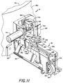
- the loader mechanism 326 places the loader arm 60 with the cartridge 22 at the eject position, as shown in Fig. 11. Thereupon, the cartridge 22 is disengaged from the loader arm 60 by operation of an ejector 342 as is explained in the ensuing description.
- the ejector 342 comprises a leg 344 extending in a generally vertical direction and terminating in a transverse strut 346 at the top of the leg 344.
- the strut 346 has a horizontal bore 348 for receiving a pivot 350 extending outwardly from the frame 322 so as to accomplish a pivoting of the ejector 342 about the pivot 350.
- the ejector 342 further comprises a guide 352 disposed at the opposite end of the leg 344 and integrally formed therewith.
- the guide 352 includes an inner sidewall 354 extending parallel to the leg 344, and an outer sidewall 356 spaced apart from the inner sidewall 354 and parallel thereto.
- the guide 352 further comprises an arm 358 which extends generally horizontally and connects the top of the inner sidewall 354 with the top of the outer sidewall 356.
- a bottom of the outer sidewall 356 is formed as a portion 360 of track and extends in a plane, parallel to the arm 358, towards the bottom edge of the inner sidewall 354.
- the track portion 360 includes a lip 362 for engagement with the cartridge 22 upon passage of the cartridge 22 through the ejector 342.
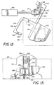
- the ejector 342 is shown in a vertical orientation in Fig. 13 and in an inclined orientation in Fig. 12, the inclined orientation of Fig. 12 occurring by virtue of a pivoting about the pivot 350.
- the leg 344 in combination with the arm 358 and the outer sidewall 356 constitute a swing arm by which the track portion is swung into and out of the travel path of the cartridge 22.
- the door 320 is secured to an end of the inner sidewall 354 facing the outer wall 282 of the incubator 36. Thereby, the door 320 becomes an integral part of the structure of the ejector 342 to move concurrently with movements of the guide 352, and to swing via the swing arm about the pivot 350.
- the door 320 has a planar form and is disposed with its planar surface facing the wall 282 of the incubator 36.
- the door 320 is virtually contiguous to the wall 282, but is separated from the wall 282 by a clearance gap (not shown) so as to facilitate relative motion between the door 320 and the wall 282.
- a clearance gap not shown
- the door 320 acts as a closure element of the cartridge ejection port 302 in the wall 282.
- the door 322 is positioned off to the side of the port 302 so as to open the port 302 to allow passage of the cartridge 22 via the port 302.
- Pivoting of the ejector 342 is accomplished by means of an electrically actuated solenoid 364 having a rod 366 extending therefrom in a transverse direction towards a slotted member 368 of the ejector 342, the member 368 being disposed on the leg 344 at a location directly beneath the strut 346.
- the member 368 has an elongated slot 370 extending in a direction parallel to the leg 344.
- a bifurcated element 372 is mounted on an end of the rod 366 opposite the solenoid 364 and includes a pair of fingers 374 and 376 which pass along opposite sides of the member 368 and support a pin 378 which extends through the slot 370.
- Activation of the solenoid 364 pushes the rod 366 against the force of a spring 380 to accomplish a rotation or pivoting of the ejector 342 in the counterclockwise direction so as to place the ejector 342 in the attitude shown in Fig. 13.
- Deactivation of the solenoid 364 allows the spring 380 to urge the ejector 342 to rotate or pivot in the clockwise direction to attain the attitude shown in Fig. 12.
- the solenoid 364 is activated by signals from the microprocessor 62, and is operated by the microprocessor 62 in synchronism with the motors 330 and 28 so as to drive the door 320 in the appropriate directions for opening and closing the port 302 in conjunction with the cartridge insertion and cartridge extraction operations of the injector 58.
- the track portion 360 serves as an extension of the track 328 when the ejector 342 is in the vertical attitude of Fig. 13.
- the cartridge 22 rides upon the track 328 and also upon the lip 362, the cartridge being held against the lip 362 by an abutment 382 disposed on a floor 384 of the track 328.
- the floor 384 forms a top surface of the housing 324.
- the floor 384 also holds the cartridge 22 in the load position, shown in Fig. 10, the floor 384 receding in the vicinity of the ejector 342 to change into a discharge chute 386.
- the receding of the floor 384 in the vicinity of the ejector 342 allows the cartridge 22 to ride upon the abutment 382 and upon the lip 362.
- the cartridge 22 Upon a pivoting of the lip 362 away from the abutment 382, the cartridge 22 falls beneath the loader arm 60 into the chute 386, and slides away to a bin (not shown) for collection of spent cartridges.
- the inner sidewall 354 comes into contact with the cartridge 22 to push the cartridge 22 down the chute 386.
- the invention has attained the objective of providing a door for the cartridge injection port and, furthermore, has provided the feature of combining movement of the door with movement of the ejector. Thereby, better temperature control of the incubator is attained essentially without adding complexity to the structure of the injector.
Landscapes
- General Health & Medical Sciences (AREA)
- Health & Medical Sciences (AREA)
- Life Sciences & Earth Sciences (AREA)
- Chemical & Material Sciences (AREA)
- Analytical Chemistry (AREA)
- Biochemistry (AREA)
- Physics & Mathematics (AREA)
- General Physics & Mathematics (AREA)
- Immunology (AREA)
- Pathology (AREA)
- Automatic Analysis And Handling Materials Therefor (AREA)
- Baking, Grill, Roasting (AREA)
- Investigating, Analyzing Materials By Fluorescence Or Luminescence (AREA)
Abstract
Description
- The present invention relates to an automated assay system operative with sample holding cartridges, the system comprising:
- a temperature controlled chamber, the chamber having a top wall and a bottom wall and a sidewall connecting the top wall with the bottom wall, the sidewall encircling the chamber, there being a port in the sidewall and a door for closing the port;
- a plurality of berths disposed in the chamber for receiving cartridges;
- a conveyor disposed in the chamber for conveying said berths along the sidewall and sequentially past said port ; and an injector.
- This type of automated assay system is known from US-A-4,908,320. US 4,908,320 describes an automated analyzer including a temperature controlled chamber having a top and bottom wall and a crylindrical sidewall, a rotor in the chamber having a plurality of slots for supporting reagent cartridges therein which may be loaded onto and removed from the rotor via an access door in the side wall of the enclosure.
- US-A-4,296,069 relates to an apparatus for transferring slides into and out of an incubator, wherein the slide transfer mechanism will either return the slide from the read station back to the incubator, or discard it through a diverter portion of the slide transfer mechanism.
- Various types of chemical tests are performed by automated test equipment, an example of testing of considerable interest being the assay of biological substances for human health care. Automated test equipment allows large numbers of test samples to be processed rapidly. Such equipment is employed in health care institutions including hospitals and laboratories. Biological fluids, such as whole blood, plasma, or serum may be tested to find evidence of disease, and to monitor therapeutic drug levels, by way of example. In the automated test instrument, samples of test fluids typically are provided in sample cups, and all of the process steps including pipetting of the sample onto an assay test element, incubation and readout of a test-result signal are performed automatically. The test instrument typically includes a series of work stations each of which performs a specific step in the test procedure. The assay element or cartridge is transported from one work station to the next by means of a conveyor, such as a carousel, to enable the test steps to be accomplished sequentially. The conveyor usually carries a plurality of the assay cartridges, each secured to a specific location on the upper surface of the conveyor. In the usual arrangement, the assay cartridges are spaced apart from each other in berths which are located along the periphery of the conveyor to facilitate automatic insertion and extraction.
- In many automated instruments, a pipette head assembly is utilized in combination with disposable pipette tips which are used typically only once, and then discarded so as to eliminate a possible source of contamination of fluids, thereby to prevent errors in the assay results. In such systems, the pipette head assembly is required to pick up a disposable pipette tip, aspirate the appropriate fluid into the pipette tip, such as a sample fluid from a sample cup, and to dispense the required volume of fluid to the assay element. The fluid dispensing system in such instruments must meet various requirements which will be understood better from the following description of the typical manner in which a fluid dispensing assembly operates in an automated instrument.
- In a typical construction of an automated instrument, the disposable pipette tips and the sample cups are arranged on carriers which are then placed on a carrier or tray supported by a movable table within the instrument. In one type of instrument, the pipette head assembly is transported horizontally (the X) direction and vertically (the Z direction), and the trays which hold the pipette tips and the sample cups are displaced from the front to the back of the instrument (the Y direction). The conveyor can be in the form of a carousel which carries the assay cartridges with rotational movement within an incubator. Initially, the pipette head assembly is driven downwardly to secure a disposable tip by frictional contact of a stem of the pipette head assembly with the interior of the disposable tip. Thereafter, a predetermined amount of fluid is aspirated into the pipette tip, and the tip is driven to a dispense position above an assay element where a predetermined volume of fluid is dispensed. Upon completion of the dispense step, the tip is discarded and a clean disposable tip secured to the stem of the pipette head assembly for the next dispense step.
- One area of concern in the accurate conduction of automated assays is the maintenance of a carefully controlled temperature in the environment of the testing. Therefore, the assay cartridges are conveyed by a suitable conveyor, such as a rotating carousel, within a temperature controlled chamber such as an incubator. The chamber includes heaters which are controlled by automatic circuitry including sensors of the chamber temperature to maintain the predesignated temperature. Indeed, it is particularly advantageous to maintain both constancy of temperature and uniformity of temperature throughout the chamber. Such temperature control can be accomplished best if the chamber is completely sealed so as to prevent the development of currents of air flowing between the environment external to the chamber and the environment within the chamber.
- A problem arises in that, in one construction of the temperature-controlled chamber an access port in the form of an elongated slot is placed in a top wall or roof of the chamber to permit insertion of a pipette for transference of liquid reagents between liquid-storage sites outside the chamber and a well within the cartridge, as well as for transference of liquid between a reservoir within the cartridge and a well in the cartridge. Furthermore, a port is provided in a sidewall of the chamber to enable a cartridge injector to insert assay cartidges onto the conveyor and to extract the cartridges when the assay is completed.
- Both of these ports are generally open. The elongated slot in the top wall has a minumum width since only the pipette stem and the pipette tip have to pass through it. Thus, flow of air through this slot between the inside and the outside of the chamber is substantially impeded. The port in the sidewall for inserting and extracting the assay cartridges has considerably larger dimensions to accommodate the assay cartridges as well as the load-unload mechanism. Accordingly, it can permit sufficient air to flow between the inside and the outside of the chamber to cause undesirable variations in the chamber temperature. The assay system of the invention has an assembly for blocking the port when assay cartridges are not being inserted into or extracted from the incubator.
- Such an assay system requires a more versatile injector than the injector of the system described in US-A-4,908,320. This problem is solved by the present invention.
- The present invention relates to an automated assay system operative with sample holding cartridges, the system comprising:
- a temperature controlled chamber, the chamber having a top wall and a bottom wall and a sidewall connecting the top wall with the bottom wall, the sidewall encircling the chamber, there being a port in the sidewall and a door for closing the port;
- a plurality of berths disposed in the chamber for receiving cartridges;
- a conveyor disposed in the chamber for conveying said berths along the sidewall and sequentially past said port; and
- an injector, characterized in that said injector is disposed outside said chamber and at said port for inserting a cartridge via said port into one of said berths and for extracting a cartridge via said port from one of said berths, which injector includes means for opening the door prior to cartridge insertion or cartridge extraction and for closing the door subsequent to a cartridge insertion or a cartridge extraction, and means for ejecting a spent cartridge subsequent to extraction of the cartridge from said chamber, and which injector includes a track for guiding a cartridge along a path into said chamber, a portion of said track being included in said ejecting means, which ejecting means is operative to swing said track portion away from said path during ejection of a cartridge, a swinging of said track portion dislodging a cartridge from the path to accomplish ejection of the cartridge.
- In accordance with the invention, a cartridge injector is disposed outside the chamber and at the port for inserting and extracting cartridges via the port.
- According to a preferred embodiment, the injector includes a loader arm which travels along the track, the loader arm engaging with a cartridge to move the cartridge along a predetermined path via the port into or out of the chamber. A portion of the track is connected via a swing arm to a pivot to enable a swinging of the track portion away from the path for dislodging a cartridge from the path, thereby to eject a spent cartridge.
- An important feature of the invention is the inclusion in the system of a door, or shutter, which provides a closure of the port. A deflection of the door away from the port provides for an opening of the port. The door is connected to the swing arm so as to move concurrently with the swinging of the track portion. Thereby, an ejection of a cartridge automatically provides for a closure of the port. A returning of the track portion to the path via a swinging motion of the swing arm deflects the door away from the port for opening the port. Thereby, operation of the door can be synchronized with insertion and extraction of a cartridge so as to open the port prior to cartridge insertion or cartridge extraction, and to close the port subsequent to a cartridge insertion or a cartridge extraction.
- The aforementioned aspects and other features of the invention are explained in the following description, taken in connection with the accompanying drawing wherein:
- Fig. 1 is a stylized view, partially diagrammatic, of a test system employing assay cartridges, the system employing a carousel for moving the cartridges among various work stations;
- Fig. 2 is a stylized view, partially diagrammatic of a pipette transport for moving the pipette between a supply of tips, sample fluid reservoirs, and compartments of an assay cartridge, the figure showing also an optical detection system for sensing the location of a tip of the pipette;
- Fig. 3 is an enlarged fragmentary view of a tip of the pipette within a light beam of the optical detection system;
- Fig. 4 is a block diagram showing a servo control loop of the pipette transport operative with a microprocessor for positioning the pipette within the vertical direction;
- Fig. 5 is a flow chart showing operation of the microprocessor;
- Fig. 6 shows details in a block of the chart of Fig. 5 relating to the computation of additional pipette travel;
- Fig. 7 is a timing diagram showing vertical movement of the pipette;
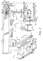
- Fig. 8 is a further view of the test system of Fig. 1 with portions of the system indicated diagrammatically, Fig. 8 including a perspective view of an incubator with portions shown cut away to disclose interior components of the incubator;
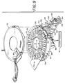
- Fig. 9 is an exploded view of apparatus of an automated assay system showing a carousel disposed within a temperature-controlled chamber and an injector for inserting and extracting cartridges from berths in the carousel;
- Figs. 10 and 11 present an enlarged fragmentary view of the system of Fig. 9 showing details in the construction of the injector, wherein Fig. 10 shows a cartridge in a loading position of the injector and Fig. 11 shows the cartridge in an eject position of the injector;
- Fig. 12 is a stylized view showing a door and ejector assembly of Fig. 10 with a sidewall of the temperature-controlled chamber being shown in phantom, the door being positioned to close a cartridge port of the chamber; and
- Fig. 13 is a simplified view of the ejector of Fig. 10 with the door and ejector assembly shown in a position wherein the cartridge port is open.
- In order to explain the apparatus and operation of the invention to accomplish a closure of an incubator port of an automated assay system automatically with operation of an injector of cartridges into and out of the incubator, it is useful, first, to describe a suitable assay system employing some form of a conveyor, such as a carousel, with a fluid dispensing system for aspirating liquid reagents into disposable pipettes from sample cups or other reagent wells and delivering the liquids to an assay cartridge on the conveyor. Accordingly, the ensuing presentation begins with a description of the overall system, followed by a description of the process of the invention accomplishing closure of the port.
- In Fig. 1, a
test system 20 provides automatically a sequence of chemical process steps to accomplish an assay of a test sample bycartridge 22. A plurality ofcartridges 22 are employed within thesystem 20 to increase the throughput rate, one process step being provided with the contents of one cartridge concurrently with the performance of other process steps with the contents of other of the cartridges. Thesystem 20 includes a turntable orcarousel 24 which is rotated about anaxle 26 by amotor 28. By way of example, themotor 28 may be mechanically coupled to thecarousel 24 by agear 30 or by a belt drive (not shown). Thecarousel 24 carries thecartridges 22 from one work station to another work station, twosuch work stations carousel 24 rotates within anincubator 36. Theincubator 36 has a heating system including a plurality of heaters represented diagrammatically by aheater 38 for maintaining a desired temperature at the various work stations. The maintenance of the desired temperature allows for a process step of incubation, this step being employed in an assay of analytes. - The
work station 32 may employ one or more pipettes, twosuch pipettes cartridge 22, as will be described hereinafter. Thepipettes pipette mechanism 44 mechanically connected to thepipettes cartridge 22. Atwork station 34, there is shown, by way of example, a fluorometer 46 for irradiating the reaction zone within thecartridge 22 and for measuring the fluorescence emitted from the fluorescent species present therein. - The
carousel 24 may be arranged so as to accommodate varying numbers ofcartridges 22. Each position, orberth 54, for holding acartridge 22 is provided in this embodiment with asmall aperture 56 to allow the radiating illumination to reach the reaction zone in thecartridge 22, and to permit the fluorescent emissions to be collected and measured. Also shown is aninjector 58 for inserting acartridge 22 in anempty berth 54, theinjector 58 having aloader arm 60 for gripping acartridge 22 during the insertion operation. Theinjector 58 also serves to extract a cartridge from aberth 54 by use of thearm 60 upon completion of a test procedure. Operation of themotor 28, thepipette mechanism 44, the fluorometer 46 and theinjector 58 are synchronized by means of timing signals provided by amicroprocessor 62. - Fig. 2 provides detail in the construction of the
pipette mechanism 44 of Fig. 1. To facilitate description of the invention, thepipette mechanism 44 will be described hereinafter as having apipette transport 64 operative with only one of the pipettes, namely, thepipette 40. Thetransport 64 provides for relative movement, in three dimensions, between thepipette 40 and a set of sample cups orreservoirs 66 located at a distance from thecartridge 22, the cups orreservoirs 66 serving to hold the fluid samples which are to be tested by thesystem 20. Thereservoirs 66 are located on atray 67 carried by a movable table 68 which also carries atray 69 holding a set oftips 70 which are to be affixed to astem 72 of thepipette 40. With reference to an X-Y-Z coordinate axes system, thepipette 40 is translatable in the X direction along abox beam 74 of thetransport 64, and the table 68 is translatable in the Y direction by riding along arail 76 of thetransport 64. Avertical drive 78 is located within thebeam 74 and serves to raise and to lower thepipette 40 in the Z direction. The X coordinate intercepts an axis of rotation of thecarousel 24, and is therefore parallel to a radius of thecarousel 24, and the Z coordinate is parallel to the axis of rotation of thecarousel 24. - A horizontal drive 80 located within the
box beam 74 drives the pipette in the X direction. Thevertical drive 78 and the horizontal drive 80 are of conventional design, and are indicated in simplified fashion in Fig. 2. In simplified fashion, thevertical drive 78 may be described as comprising awheel 82 slidably mounted to aspline shaft 84 which, alternatively, may have a square cross section. Theshaft 84 is rotated by amotor 86. The horizontal drive 80 includes a base 88 which slides in the X direction along thebeam 74 in response to rotation of amotor 90. Themotor 90 drives a belt 92 through apulley 94, the belt 92 being connected to thebase 88 for translating the base 88 upon rotation of thepulley 94 by themotor 90. Afixture 96 upstanding from the base 88 slides thewheel 82 along theshaft 84 upon movement of the base 88 so that thewheel 82 stays in fixed position relative to thebase 88. Thepipette 40 passes through the base 88 so as to be translated in the X direction by thebase 88. Thewheel 82 is mechanically connected to thepipette 40, as by gear teeth on thewheel 82, or by means of a belt drive (not shown). The mechanical connection of thewheel 82 to thepipette 40 provides for a translation of thepipette 40 in the Z direction upon rotation of thewheel 82 by themotor 86. Abelt drive 98 may be employed, similarly, for driving the table 68 in the Y direction in response to rotation of amotor 100 affixed to therail 76. - As noted above in the description of the system of Fig. 1, the
motor 28 is under control of themicroprocessor 62. Similarly, themotors microprocessor 62. Connections of themotors pipette 40 can be synchronized with a positioning of thecartridge 22 by thecarousel 24 to a location directly beneath thebeam 74. In order to provide access to thecartridge 22 by thepipette 44, aslot 102 is provided in atop wall 104 of theincubator 36. Theslot 102 extends parallel to a radius of thecarousel 24, and is parallel to thebeam 74. The location of theslot 102 relative to thebeam 74 permits thestem 72 of thepipette 40 to be lowered through theslot 102 selectively above a desired well or compartment of a plurality ofcompartments 106 of thecartridge 22. The length of theslot 102 is commensurate with the length of thecartridge 22 to permit displacement of thestem 72 in the X direction for alignment with a selected one of thecompartments 106. Theslot 102 is relatively narrow, and has a width large enough to clear thestem 72 and thetip 70 mounted on the distal end of thestem 72. With respect to the overall dimensions of theincubator 36, the area occupied by theslot 102 is sufficiently small to preclude any significant amount of air flow between the interior and the exterior of theincubator 36. Thereby, theslot 102 has no more than a negligible effect in the control of the incubator temperature, which temperature is controlled by the heater 38 (Fig. 1). - In an embodiment of an automated assay instrument, an optical detection system 108 is provided to signal the
microprocessor 62 when thetip 70 of thepipette 40 has advanced in the downward direction to a predetermined distance from the selectedcompartment 106. The detection system 108 comprises alight source 110 which, by way of example, may be a semiconductor diode which emits infrared radiation. The detection system 108 also comprises alight detector 112, the light being indicated by alight beam 114. Thedetector 112, which may comprise a semiconductor photodiode, emits an electric current alongline 116 in response to light of thebeam 114 incident upon thedetector 112. - The detection system 108 includes
electrical comparison circuitry 118 for measuring the magnitude of the current online 116. By way of example in the construction of thecircuitry 118, thecircuitry 118 comprises acomparator 120 and aresistive voltage divider 124 providing a reference voltage to thecomparator 120. Thedivider 124 comprises a potentiometer for allowing manual adjustment of the reference voltage for initial alignment of the detection system 108. Thedivider 124 provides for selection of a comparator reference voltage in accordance with the degree of optical transparency of thetip 70. - In the operation of the detection system 108, the full strength of the
light beam 114 is incident upon thedetector 112 in the absence of thepipette 40. By way of example, thepipette 40 may be at the location of one of thereservoirs 66, as indicated in phantom view of the pipette. During maximum intensity of the received optical signal at thedetector 112, a maximum current and voltage appear online 116. During descent of thepipette 40, thetip 70 interrupts thelight beam 114. Theline 116 is connected to an input terminal of thecomparator 120 which outputs a logic-1 signal to themicroprocessor 62 under conditions of maximum illumination of thedetector 112, as occurs prior to interruption of thelight beam 114 by thepipette 40. Interruption of thelight beam 114 greatly reduces the intensity of light received at thedetector 112 so that thecomparator 120 outputs a logic-0 signal to themicroprocessor 62. The extent of the interruption of the light depends on the degree of the transparency of thetip 70. Thetip 70 is fabricated typically of a translucent polymeric material. - Liquid reagent is drawn into the
pipette tip 70 by vacuum and expelled from thetip 70 by pressure delivered to thepipette 40 by asuction tube 126 under control of asuction control unit 128. Thetube 126 is flexible and of sufficient length to connect thesuction control unit 128 with thepipette 40 at all locations of thepipette 40. Thecontrol unit 128 is connected to themicroprocessor 62 which commands thecontrol unit 128 to apply vacuum for inducting liquid, and for releasing vacuum and applying positive pressure, if necessary, to expel the liquid reagent. Induction of liquid sample is done from a selected one of thereservoirs 66. Expelling of the liquid sample is accomplished only when thetip 70 is in the position for dispensing the liquid to the selected one of thecompartments 106 in the designatedcartridge 22. It is noted also that induction of liquid reagent can be accomplished at one of thecompartments 106 of thecartridge 22 to be dispensed in another of thecompartments 106. In this respect, a reservoir for storage of liquid reagent can be located directly within thecartridge 22. The location of thevarious reservoirs 66 of the table 68 is stored in a memory of themicroprocessor 62. This enables themicroprocessor 62 to move the table 68 to a specific address in the Y direction, and to move thepipette 40 to a specific address in the X direction, the X and the Y components of the address fully identifying the requisite one of thereservoirs 66. In similar fashion, themicroprocessor 62 stores locations of theavailable tips 70 held by the table 68 so that successive ones of thetips 70 can be selected for affixation to thestem 72. - The
transport 64 is operative in the process of affixing atip 70 to thestem 72 of apipette 40, and in the detachment of thetip 70 from thestem 72. The procedure begins by a lifting of thepipette 40 so that thetip 70 clears theslot 102. Thepipette 40 is then free to move along thebeam 74 to anextractor 130. Theextractor 130 has asemicircular channel 132 cut out in the edge of a horizontal portion of theextractor 130, thechannel 132 having a diameter large enough to permit clearance of thestem 72 by thechannel 132, but small enough to permit engagement of thechannel 132 with thetip 70. Under commands of themicroprocessor 62, the pipette is brought towards theextractor 130 with thetip 70 being below thechannel 132. Thestem 72 enters thechannel 132 after which thepipette 40 is raised to engage thetip 70 with theextractor 130. Thetip 70 remains stationary as thestem 72 lifts out of thetip 70. Thereupon, thetip 70 falls into abin 134 for collection of usedtips 70. It is advisable to employ theextractor 130 at the beginning of operation of thetest system 20 to ensure that thestem 72 is free for reception of anew tip 70. - After ensuring that the
stem 72 is free for reception of atip 70, thepipette 40 is brought, by displacement in the X direction, to a location above the table 68, whereupon the table 68 is translated in the Y direction to bring thestem 72 above and in registration with a selectedtip 70 held by the table 68. Thepipette 40 then advances downward to make frictional contact with the interior surface of thetip 70. Thereupon, the pipette is raised, and the tip is retained on the distal end of thestem 72 by friction forces. - With reference also to Fig. 3, the distal end of the
stem 72 is shown making frictional contact with the surface of aninternal channel 136 of thetip 70. Thechannel 136 extends along a central longitudinal axis of thetip 70 from one end of the tip to the opposite end of the tip. Thechannel 136 has a circular cross-sectional shape of varying diameter, the diameter being larger at thetop end 138 than at thebottom end 140. As thestem 72 advances downwardly into thechannel 136, constriction of thechannel 136 produces frictional forces which tighten thetip 70 upon thestem 72. These frictional forces are sufficient to ensure a secure attachment of thetip 70 to thestem 72 during transfer of liquid reagent during test procedures of thesystem 20. However, the frictional forces are sufficiently small to permit theextractor 130 to slide thetip 70 off of thestem 72 upon completion of a transfer of liquid reagent. - With respect to the operation of the
system 20, it is noted that the manner of affixing thestem 72 to thetip 70 provides substantial uniformity in the locations ofsuccessive tips 70 upon thestem 72. However, in view of the flexibility of the plastic material of thetip 70 brought about by contact with the relatively rigid tube of thestem 72, and in view of some variation in frictional forces among thetips 70, it has been found that there is slight variation among the locations of the bottom ends 140 of thetips 70 relative to the distal end of thestem 72. This variation is sufficient to serve as a source of inaccuracy to the dispensing of liquid in thecompartments 106 of thecartridge 22. The system automatically corrects for these variations in tip location by sensing the location of thebottom end 140 of thetip 70 by means of thelight beam 114. The procedure for correcting for the variations in tip location is explained further with reference to the diagram of Fig. 4 and the flow charts of Figs. 5-6. - Fig. 4 shows a feedback circuit 142 for interconnecting the
microprocessor 62 with themotor 86 for operation of thevertical pipette drive 78 disclosed in Fig. 2. As shown in Fig. 4, the circuit 142 includes asummer 144, afilter 146, anamplifier 148, a steppingmotor controller 150, a shaft angle encoder 152 (also shown in Fig. 2), amemory 154 of themicroprocessor 62, and anentry device 156, such as a keyboard, for entering data into thememory 154. In a preferred embodiment, all of themotors - In operation, for lowering the
pipette 40 towards the cartridge 22 (Fig. 2), themicroprocessor 62 successively enters new locations on the path of travel of thepipette 40 in the Z direction. Location signals of themicroprocessor 62 are applied to one input terminal of thesummer 144. The present location of thetip 70, as estimated by theencoder 152 is applied to a second input terminal of thesummer 144 to be subtracted from the value input at the first terminal of thesummer 144. It is noted that theencoder 152 provides an accurate value of the location of thepipette stem 72, but not of thetip 70, because the position of thetip 70 relative to thestem 72 varies from tip to tip because of the frictional fit explained above. Therefore, a value of shaft angle outputted by theencoder 152 can be taken only as an estimate of the true position of thetip 70. - The signals outputted by the
encoder 152 and by themicroprocessor 62 are formatted digitally. Thesummer 144 forms the difference of these two signals and applies the difference as the loop error signal to be filtered by thefilter 146. In accordance with the usual practice in the construction of the feedback loops, thefilter 146 may be a low-pass filter, and may include a lead-lag filter component. Thefilter 146 provides stability to the feedback loop. An output signal of thefilter 146 is amplified by theamplifier 150, and is applied via thecontroller 150 to the steppingmotor 86. The loop gain and bandwidth, as established by theamplifier 150 and thefilter 146, in conjunction with themotor 86 determine the dynamic response of the loop in a manner well known in the design of servomechanisms. Themotor 86 rotates towards the rotational position commanded by themicroprocessor 62. As themotor 86 rotates, thevertical drive 78 lowers thepipette 40. By way of alternative embodiment in the construction of the feedback circuit of Fig. 4, it is noted that the functions of thesummer 144 and thefilter 146 can be accomplished directly within themicroprocessor 62 by suitable programming of themicroprocessor 62. In such a case, themicroprocessor 62 outputs the error signal directly to theamplifier 148 for driving themotor 86. - With respect to the circuit shown in Fig. 4, the
microprocessor 62 continues to input further values of position along the path traveled by thepipette 40 until the light-beam comparison circuit 118 signals themicroprocessor 62 of a break in the light beam. The location of thetip 70 is now known accurately by virtue of contact of thetip 70 with thelight beam 114. Thepipette 40 now travels through an additional distance to bring thetip 70 into the dispensing position relative to thecartridge 22. The value of the additional distance of positional travel is based on data stored in thememory 154. Themicroprocessor 62 reads thememory 154 to obtain the travel data. A person calibrating thetest system 20 provides the requisite data on additional travel based on a knowledge of a reference point which, in a preferred embodiment is the height of thecartridge 22 relative to atop surface 158 of thecarousel 24. This height data is entered via theentry device 156 to thememory 154. By way of example, theentry device 156 may be constructed as a touch panel located at a position of convenience to an operator of thesystem 20. - The operation of the feedback circuit 142 may be explained further with reference to Fig. 2 and with reference to the timing diagram of Fig. 7. Prior to the lowering of the
pipette 40, thetip 70 is at a sufficiently high elevation to permit transporting thepipette 40 in the X direction between thecarousel 24 and the table 68. This is referred to in Fig. 7 as the transport level. Thepipette 40 then undergoes its initial descent during an interval of time identified in Fig. 7. The initial descent interval ends with the breaking of thelight beam 114. Thereupon, there is the final interval of descent in which thepipette 40 descends the additional travel. This brings the pipette tip to the dispense level indicated in Fig. 7. After completion of a dispensing interval of time, the feedback circuit 142 raises thepipette 40 back to the transport level during a retraction interval shown in Fig. 7. Also shown in Fig. 7 is a safety level which will be described with reference to the flow charts of Figs. 5-6. - With reference to Fig. 5, the inventive feature of lowering the pipette to the
cartridge 22 while compensating for variations in positions of thetip 70 is explained with reference to a flow chart. The flow chart describes operation of themicroprocessor 62 of Fig. 2 for operating the vertical pipette drive 78 (Figs. 2 and 4) for lowering thepipette 40 to dispense liquid reagent in acompartment 106 of thecartridge 22. Initiation of the pipette descent toward thecartridge 22 occurs atblock 160. Atblock 162, the determination is made as to whether the light beam 114 (Fig, 2) is present. Themicroprocessor 62 is informed as to the status of the light beam by the signal outputted by thecomparison circuitry 118. When thepipette 40 is in an elevated position, there is no blockage of thelight beam 114 and, accordingly, thelight beam 114 should be present and thecomparator 120 should be outputting the logic-1 signal indicating full intensity of thelight beam 114. If the beam is not present, then, atblock 164, a person operating thetest system 20 is signaled to correct an apparent fault in the equipment of thesystem 20. - If the light beam is present, the procedure advances to block 166 wherein the
microprocessor 62 directs the lowering of thepipette 40 in the manner described above with reference to Fig. 4. Therein, themicroprocessor 62 continually inputs new positions along the path of travel of thepipette 40 at a rate commensurate with the dynamic response of the feedback loop 142. Periodically, during the lowering of thepipette 40, themicroprocessor 62 observes output signals of thecomparison circuitry 118 to determine whether there has been an interruption of thelight beam 114, this determination being performed atblock 168. - Assuming that no interruption of the
light beam 114 by thepipette 40 has occurred, then operation proceeds alongline 170 to block 172 to determine whether the safety level (shown in Fig. 7), has been reached. There is the possibility of a system malfunction wherein thestem 72 of thepipette 40 has failed to secure thetip 70 at the table 68. This could occur for a variety of reasons, such as operator negligence in filling the table 68 with the set oftips 70, or the possibility of a cracked tip which fails to provide adequate friction for securing the tip to thestem 72. Since the shaft angle encoder 152 (Fig. 4) continually outputs position data to themicroprocessor 62, themicroprocessor 62 has knowledge of the location of the distal end of thestem 72. As the distal end of thestem 72 approaches the vicinity of thelight beam 114, there should be an interruption of thebeam 114 by thetip 70, assuming thetip 70 is present. The safety level is the lowest point at which themicroprocessor 62 will allow thestem 72 to drop without interruption of thebeam 114. If the safety level is reached, then themicroprocessor 62 concludes that thetip 70 is absent, and operation proceeds to block 174 wherein themicroprocessor 62 orders retraction of thepipette 40 to the transport level. As noted hereinabove, at the transport level, thepipette 40 clears thetop wall 104 of theincubator 36 so that thestem 72 is fully visible to an operator for performing remedial action. Fromblock 174, operation proceeds to block 176 wherein the operator is signaled to take remedial action. - During normal operation of the
system 20, thetip 70 is present on thestem 72 and, accordingly, atblock 172 the safety level would not be reached without interruption of thelight beam 114. Accordingly, operation proceeds fromblock 172 alongline 178 back to block 166 wherein themicroprocessor 62 continues to lower the pipette at the preset rate. The operation continues in repetitive fashion through theblocks light beam 114 occurs atline 180. The interruption of thelight beam 114 is signaled to themicroprocessor 62 by a change in the output signal of thecomparison circuitry 118 such that the signal changes from logic-1 to Iogic-0. - Assuming that the
tip 70 is present, then, upon the interruption of the light beam atline 180, the output signal of thecomparison circuitry 118 is at logic-0 to indicate to themicroprocessor 62 that thetip 70 is filled with the liquid reagent, and that thetip 70 has reached the position of thelight beam 114 along the path of travel of thetip 70 towards thecartridge 22. Accordingly, atblock 182, themicroprocessor 62 determines the position of the dispense level (Fig. 7) so as to compute the additional amount of travel required by thetip 70 to reach the dispense level. The operation withinblock 182 will be described in further detail with reference to Fig. 6. - In Fig. 5, the operation proceeds from
block 182 vialine 186 to block 188 wherein thepipette 40 is lowered further to locate thetip 70 at the dispense level. This lowering of the pipette is accomplished, in the manner disclosed hereinabove with reference to the feedback circuit 142 of Fig. 4, wherein themicroprocessor 62 inputs further locations along the travel path of the pipette to bring thetip 70 to the dispense level. Thereafter, atblock 190 themicroprocessor 62 commands thesuction control unit 128 to dispense liquid to the selectedcompartment 106 of thecartridge 22. Then atblock 192, thepipette 40 is retracted back from thecartridge 22 to the transport level. Thesystem 20 can now initiate other steps in the testing procedures of the samples carried by various ones of thecartridges 22. - Fig. 6 shows details in the procedure of block 182 (Fig. 5) for checking the filling of the pipette tip followed by the computation of the additional travel of the pipette. The procedure at
line 180 proceeds to block 194 to check the intensity of the light beam. In the event that, atblock 194, the light is fully obscured, the signal of thecomparison circuit 118 is at logic-0, as was noted hereinabove, which allows themicroprocessor 62 to determine, atblock 198, that a loaded pipette is present. Thereupon, atblock 200 the microprocessor reads the present pipette position as outputted by the encoder 152 (Fig. 4). This is followed, atblock 202, by a reading of the position data of thecartridge 22, which data has been stored in the memory 154 (Fig. 4). - The cartridge position data designates the location of a top surface of the
cartridge 22 relative to thetop surface 158 of thecarousel 24. Since the distance between thelight beam 114 and thecarousel surface 158 is known and fixed, the inputting of this cartridge data is equivalent to giving the microprocessor the distance between the top surface of thecartridge 22 and thebeam 114. Accordingly, atblock 204, the additional distance between thebeam 114 and thecartridge 22 is added to the vertical distance already traveled by thepipette 40, the vertical distance being provided by theencoder 152. This gives the reading of theencoder 152 which will be obtained when thepipette tip 70 reaches the dispense level. This information is used by themicroprocessor 62 in operating the circuit of Fig. 4 for continued lowering of thepipette 40. Accordingly, the operation can now proceed vialine 186 to block 188 as has been disclosed above with reference to Fig. 5. - The timing diagram of Fig. 7 has already been referred to in the description of the circuitry of Fig. 4 and the procedure of Figs. 5 and 6. Briefly, the diagram of Fig. 7 shows the descent of the
pipette tip 70 at a fixed rate during the initial descent interval. This is followed by a pause in which the condition of the light beam is observed, followed by the final descent in which thepipette tip 70 is brought to the dispense level. At the conclusion of the dispense interval, thetip 70 is retracted to the transport level. The safety level is disposed between the light beam level and the dispense level. - The foregoing description provides for operation of the
test system 20 in a fashion which allows the pipette to be lowered with an accuracy which is independent of the position of thepipette tip 70 on thepipette stem 72. - With reference to Figs. 1, 8 and 9, there is provided further details in the construction of a preferred embodiment of the
incubator 36 and its operation with thesystem 20. In addition to the top wall which serves as theroof 104 of theincubator 36 and is located above thecarousel 24, theincubator 36 further comprises a bottom wall which serves as afloor 280 of theincubator 36 and is located below thecarousel 24, and two sidewalls wherein one of the sidewalls is anouter wall 282 which extends from theroof 104 to thefloor 280 and the second of the sidewalls is aninner wall 284 which extends from theroof 104 toward a central portion of thecarousel 24. Theroof 104 has an annular shape. An upper region 286 of theincubator 36 is bounded by theroof 104, thetop surface 158 of thecarousel 24, theouter wall 282 and theinner wall 284. The upper region 286 of theincubator 36 has a toroidal shape. Theslot 102 in theroof 104 is relatively narrow, and is surrounded by agrommet 294. Theslot 102 has a width large enough to clear thestem 72 and thetip 70 mounted on the distal end of thestem 72. - The
incubator 36 further comprises two heaters, namely, atop heater 296 supported by theroof 104, and abottom heater 298 supported by thefloor 280 for controlling the incubator temperature. Thebottom heater 298 is located in a lower region 300 of theincubator 36, between thecarousel 24 and thefloor 280. Aninjection port 302 is provided in theouter wall 282 facing theinjector 58 to provide access to theloader arm 60 for inserting acartridge 22 in aberth 54 of thecarousel 24, and for extracting thecartridge 22 from theberth 54. Aframe 304 is located within the upper region 286 for supporting sensors useful in the operation of thesystem 20, onesuch sensor 306 being provided for sensing the incubator temperature. Theframe 304 is secured by a bracket 308 to theouter wall 282. By way of example in the construction of theframe 304, theframe 304 may be constructed as a circuit board for supporting electronic circuitry (not shown) such as a preamplifier for amplifying electrical signals provided by thesensor 306. By way of further example, anadditional sensor 310 may also be mounted on theframe 304 for sensing the humidity because there are tests in which the humidity affects the outcome of the test, and a knowledge of the humidity can provide a more accurate reading of the test.Electrical cables top heater 296, thebottom heater 298, and thesensors incubator 36. - In accordance with the invention, the
injector 58 is provided with a door or shutter 320 (shown in Figs. 9-13) for closing, or blocking, the injection port 302 (Fig. 8) in theouter wall 282 of theincubator 36. In accordance with a major feature of the invention, operation of thedoor 320 is performed automatically and in synchronism with the operation of theinjector 58 during performance of the functions of insertion of acartridge 22 into theincubator 36, extraction of acartridge 22 from theincubator 36, and ejection of a spent cartridge, namely a cartridge for which the test procedure has been completed. In particular, the mechanism for positioning thedoor 320, as will be described in further detail hereinafter, moves thedoor 320 away from theport 302 for opening theport 302 prior to cartridge insertion and also prior to cartridge extraction. Thedoor 320 is moved back in front of theport 302 to close theport 302 subsequent to the insertion of a cartridge and also subsequent to the extraction of a cartridge. These aspects of the invention are explained in the ensuing detailed description of theejector 58. - With reference to Figs. 9-13, the
injector 58 includes aframe 322 for securing theinjector 58 to theouter sidewall 282 of theincubator 36. Ahousing 324 extends radially outward from theframe 322 and supports aloader mechanism 326 including theloader arm 60 which engages with acartridge 22 for advancing thecartridge 22 along atrack 330 in the top side of thehousing 324. Thetrack 328 guides thecartridge 22 along a path through theport 302 into theincubator 36 for depositing thecartridge 22 in aberth 54 of thecarousel 24. - The
loader mechanism 326 includes a stepping motor 330 (Fig. 9) which drives abelt 332 around apulley 334 for connecting with theloader arm 60 via a projection 336 (shown in phantom in Figs. 10 and 11) which extends downwardly from theloader arm 60. By virtue of the connection of theloader arm 60 with thebelt 332, rotation of the steppingmotor 330 in one direction advances thearm 60 towards theincubator 36 while rotation of themotor 330 in the reverse direction retracts thearm 60 from theincubator 36. Themotor 330 is operated in response to signals from themicroprocessor 62 in the same fashion as has been described hereinabove for themotors arm 60 extends in the longitudinal direction along thetrack 328 and curves in its end portions via twofingers 338 and 340 (Fig. 10) for receiving thecartridge 22. Thecartridge 22 is inserted manually into the right side of theloader arm 60 as viewed in Fig. 10. During transfer of thecartridge 22 from thearm 60 to aberth 54, thecartridge 22 is disengaged from thearm 60 by rotating thecarousel 24 momentarily in the counterclockwise direction. Conversely, during the extraction process, thecartridge 22 is placed in engagement with thearm 60 by rotating thecarousel 24 momentarily in the clockwise direction. Upon extraction of thecartridge 22 from theincubator 36, theloader mechanism 326 places theloader arm 60 with thecartridge 22 at the eject position, as shown in Fig. 11. Thereupon, thecartridge 22 is disengaged from theloader arm 60 by operation of anejector 342 as is explained in the ensuing description. - The
ejector 342 comprises aleg 344 extending in a generally vertical direction and terminating in atransverse strut 346 at the top of theleg 344. Thestrut 346 has ahorizontal bore 348 for receiving apivot 350 extending outwardly from theframe 322 so as to accomplish a pivoting of theejector 342 about thepivot 350. Theejector 342 further comprises aguide 352 disposed at the opposite end of theleg 344 and integrally formed therewith. Theguide 352 includes aninner sidewall 354 extending parallel to theleg 344, and anouter sidewall 356 spaced apart from theinner sidewall 354 and parallel thereto. Theguide 352 further comprises anarm 358 which extends generally horizontally and connects the top of theinner sidewall 354 with the top of theouter sidewall 356. A bottom of theouter sidewall 356 is formed as aportion 360 of track and extends in a plane, parallel to thearm 358, towards the bottom edge of theinner sidewall 354. Thetrack portion 360 includes alip 362 for engagement with thecartridge 22 upon passage of thecartridge 22 through theejector 342. Theejector 342 is shown in a vertical orientation in Fig. 13 and in an inclined orientation in Fig. 12, the inclined orientation of Fig. 12 occurring by virtue of a pivoting about thepivot 350. Theleg 344 in combination with thearm 358 and theouter sidewall 356 constitute a swing arm by which the track portion is swung into and out of the travel path of thecartridge 22. - In accordance with the invention, the
door 320 is secured to an end of theinner sidewall 354 facing theouter wall 282 of theincubator 36. Thereby, thedoor 320 becomes an integral part of the structure of theejector 342 to move concurrently with movements of theguide 352, and to swing via the swing arm about thepivot 350. Thedoor 320 has a planar form and is disposed with its planar surface facing thewall 282 of theincubator 36. Thedoor 320 is virtually contiguous to thewall 282, but is separated from thewall 282 by a clearance gap (not shown) so as to facilitate relative motion between thedoor 320 and thewall 282. In the situation of the inclined orientation of theejector 342, as depicted in Fig. 12, thedoor 320 acts as a closure element of thecartridge ejection port 302 in thewall 282. In the case of the vertical orientation of theejector 342, as depicted in Fig. 13, thedoor 322 is positioned off to the side of theport 302 so as to open theport 302 to allow passage of thecartridge 22 via theport 302. - Pivoting of the
ejector 342 is accomplished by means of an electrically actuatedsolenoid 364 having arod 366 extending therefrom in a transverse direction towards a slottedmember 368 of theejector 342, themember 368 being disposed on theleg 344 at a location directly beneath thestrut 346. Themember 368 has an elongatedslot 370 extending in a direction parallel to theleg 344. Abifurcated element 372 is mounted on an end of therod 366 opposite thesolenoid 364 and includes a pair offingers member 368 and support apin 378 which extends through theslot 370. Activation of thesolenoid 364 pushes therod 366 against the force of aspring 380 to accomplish a rotation or pivoting of theejector 342 in the counterclockwise direction so as to place theejector 342 in the attitude shown in Fig. 13. Deactivation of thesolenoid 364 allows thespring 380 to urge theejector 342 to rotate or pivot in the clockwise direction to attain the attitude shown in Fig. 12. Thesolenoid 364 is activated by signals from themicroprocessor 62, and is operated by themicroprocessor 62 in synchronism with themotors door 320 in the appropriate directions for opening and closing theport 302 in conjunction with the cartridge insertion and cartridge extraction operations of theinjector 58. - The
track portion 360 serves as an extension of thetrack 328 when theejector 342 is in the vertical attitude of Fig. 13. In this condition of theejector 342, thecartridge 22 rides upon thetrack 328 and also upon thelip 362, the cartridge being held against thelip 362 by anabutment 382 disposed on afloor 384 of thetrack 328. Thefloor 384 forms a top surface of thehousing 324. Thefloor 384 also holds thecartridge 22 in the load position, shown in Fig. 10, thefloor 384 receding in the vicinity of theejector 342 to change into adischarge chute 386. The receding of thefloor 384 in the vicinity of theejector 342 allows thecartridge 22 to ride upon theabutment 382 and upon thelip 362. Upon a pivoting of thelip 362 away from theabutment 382, thecartridge 22 falls beneath theloader arm 60 into thechute 386, and slides away to a bin (not shown) for collection of spent cartridges. During the pivoting of thelip 362 away from theabutment 382, theinner sidewall 354 comes into contact with thecartridge 22 to push thecartridge 22 down thechute 386. - Thereby, the invention has attained the objective of providing a door for the cartridge injection port and, furthermore, has provided the feature of combining movement of the door with movement of the ejector. Thereby, better temperature control of the incubator is attained essentially without adding complexity to the structure of the injector.
- It is to be understood that the above described embodiment of the invention is illustrative only, and that modifications thereof may occur to those skilled in the art. Accordingly, this invention is not to be regarded as limited to the embodiment disclosed herein, but is to be limited only as defined by the appended claims.
Claims (4)
- An automated assay system (20) operative with sample holding cartridges (22), the system (20) comprising:a temperature controlled chamber (36), the chamber (36) having a top wall (104) and a bottom wall (280) and a sidewall (282) connecting the top wall (36) with the bottom wall (280), the sidewall encircling the chamber (36), there being a port (302) in the sidewall (282) and a door (320) for closing the port (302);a plurality of berths (54) disposed in the chamber (36) for receiving cartridges (22);a conveyor (24) disposed in the chamber (36) for conveying said berths (54) along the sidewall (282) and sequentially past said port (302); characterized in that an injector (58) is disposed outside said chamber (36) and at said port (302) for inserting a cartridge (22) via said port (302) into one of said berths (54) and for extracting a cartridge (22) via said port (302) from one of said berths (54), which injector (58) includes means for opening the door (320) prior to cartridge (22) insertion or cartridge (22) extraction and for closing the door (320) subsequent to a cartridge (22) insertion or a cartridge (22) extraction, and means (342) for ejecting a spent cartridge (22) subsequent to extraction of the cartridge (22) from said chamber (36), and which injector (58) includes a track (328) for guiding a cartridge (22) along a path into said chamber (36), a portion of said track (328) being included in said ejecting means (342), which ejecting means (342) is operative to swing said track portion (328) away from said path during ejection of a cartridge (22), a swinging of said track portion (328) dislodging a cartridge (22) from the path to accomplish ejection of the cartridge (22).
- A system (20) according to claim 1 wherein
said ejecting means (342) further comprises a pivot (350) and a swing arm (358) connecting said pivot (350) to said track portion (328), said swing arm (358) supporting said track portion (328) during a swinging of said track portion (328);
said door (320) is secured to said swing arm (358) to swing concurrently with a swinging of said track portion (328);
a swinging of said track portion (328) by said swing arm (358) away from said path brings said door (320) into a position of closure of said port (302), and a returning of said track portion (328) to said path by said swing arm (358) advances said door (320) to open said port (302). - A system (20) according to claim 1 wherein said injector (58) further comprises:
a loader arm (60) for engaging with a cartridge (22) to advance the cartridge (22) along said path;
first drive means for pivoting said swing arm (358);
second drive means for moving said loader arm (60) along said path; and
wherein said system (20) further comprises means for synchronizing operation of said first and said second drive means for opening said port (302) prior to insertion or extraction of a cartridge (22). - A system (20) according to claim 3 wherein
said first drive means comprises a solenoid (364);
said second drive means comprises a stepping motor (330); and
said synchronizing means is operatively coupled to said conveyor (24) to position a berth (54) at said port during cartridge (22) insertion or cartridge (22) extraction, the conveyor (24) being a rotatable carousel.
Applications Claiming Priority (3)
| Application Number | Priority Date | Filing Date | Title |
|---|---|---|---|
| US07/655,541 US5192506A (en) | 1991-02-14 | 1991-02-14 | Incubator port closure for automated assay system |
| US655541 | 1991-02-14 | ||
| PCT/US1992/000963 WO1992014550A1 (en) | 1991-02-14 | 1992-02-03 | Incubator port closure for automated assay system |
Publications (2)
| Publication Number | Publication Date |
|---|---|
| EP0525180A1 EP0525180A1 (en) | 1993-02-03 |
| EP0525180B1 true EP0525180B1 (en) | 1996-09-25 |
Family
ID=24629304
Family Applications (1)
| Application Number | Title | Priority Date | Filing Date |
|---|---|---|---|
| EP92907524A Expired - Lifetime EP0525180B1 (en) | 1991-02-14 | 1992-02-03 | Incubator port closure for automated assay system |
Country Status (10)
| Country | Link |
|---|---|
| US (1) | US5192506A (en) |
| EP (1) | EP0525180B1 (en) |
| JP (1) | JP2532807B2 (en) |
| AT (1) | ATE143290T1 (en) |
| AU (1) | AU644278B2 (en) |
| CA (1) | CA2071848A1 (en) |
| DE (1) | DE69214048T2 (en) |
| DK (1) | DK0525180T3 (en) |
| ES (1) | ES2094905T3 (en) |
| WO (1) | WO1992014550A1 (en) |
Families Citing this family (66)
| Publication number | Priority date | Publication date | Assignee | Title |
|---|---|---|---|---|
| DE69331861T2 (en) * | 1992-01-16 | 2002-08-29 | Fuji Photo Film Co., Ltd. | Chemical analysis system |
| US5340540A (en) * | 1993-05-03 | 1994-08-23 | Eastman Kodak Company | Cap raising mechanism for an incubator |
| US5374395A (en) * | 1993-10-14 | 1994-12-20 | Amoco Corporation | Diagnostics instrument |
| US5490972A (en) * | 1994-04-29 | 1996-02-13 | Johnson & Johnson Clinical Diagnostics, Inc. | Raising mechanism for incubator cover |
| US5697409A (en) * | 1996-02-21 | 1997-12-16 | Biomerieux Vitek, Inc. | Diluting and pipetting stations for sample testing machine |
| US5762873A (en) * | 1996-02-21 | 1998-06-09 | Biomerieux Vitek, Inc. | Automatic sample testing machine |
| US5736102A (en) * | 1996-02-21 | 1998-04-07 | Biomerieux Vitek, Inc. | Test sample positioning system |
| US6156565A (en) * | 1996-02-21 | 2000-12-05 | Biomerieux, Inc. | Incubation station for test sample cards |
| US6129428A (en) * | 1996-08-05 | 2000-10-10 | Kendro Laboratory Products Gmbh | Storage device for objects, storage station and air-conditioned cabinet |
| ES2322859T3 (en) | 1998-05-01 | 2009-06-30 | Gen-Probe Incorporated | AUTOMATED DIAGNOSTIC ANALYZER. |
| US8337753B2 (en) * | 1998-05-01 | 2012-12-25 | Gen-Probe Incorporated | Temperature-controlled incubator having a receptacle mixing mechanism |
| US6214292B1 (en) | 1998-07-01 | 2001-04-10 | Jose Maria Las Navas Garcia | Sample auto-loader for use with an analytical combustion furnace |
| US6348176B1 (en) | 1999-02-11 | 2002-02-19 | Careside, Inc. | Cartridge-based analytical instrument using centrifugal force/pressure for metering/transport of fluids |
| US6531095B2 (en) | 1999-02-11 | 2003-03-11 | Careside, Inc. | Cartridge-based analytical instrument with optical detector |
| US6391264B2 (en) | 1999-02-11 | 2002-05-21 | Careside, Inc. | Cartridge-based analytical instrument with rotor balance and cartridge lock/eject system |
| AU3359100A (en) * | 1999-02-11 | 2000-08-29 | Careside, Inc. | Cartridge-based analytical instrument |
| US6245297B1 (en) * | 1999-04-16 | 2001-06-12 | Pe Corporation (Ny) | Apparatus and method for transferring small volumes of substances |
| DE10024581A1 (en) | 2000-05-19 | 2001-11-29 | Kendro Lab Prod Gmbh | Climate cabinet |
| AU2001289853A1 (en) * | 2000-09-04 | 2002-03-22 | Zeptosens Ag | Multianalyte determination system and methods |
| DE50210923D1 (en) | 2001-01-26 | 2007-10-31 | Liconic Ag | AIR CONDITIONED STORAGE CABINET |
| FR2820756B1 (en) * | 2001-02-09 | 2004-01-23 | Daniel Attias | INCUBATOR AND INCUBATION PROCESS ENDING THE ORGANIZATION SET TO INCUBATE |
| US7217391B2 (en) * | 2001-03-16 | 2007-05-15 | Beckman Coulter, Inc. | Rotary incubation station for immunoassay systems |
| JP4562165B2 (en) * | 2002-08-28 | 2010-10-13 | 株式会社東海ヒット | Microscope incubator |
| EP1443101B1 (en) | 2002-12-18 | 2012-02-22 | Liconic Ag | Incubator with moveable support |
| US7314341B2 (en) | 2003-01-10 | 2008-01-01 | Liconic Ag | Automatic storage device and climate controlled cabinet with such a device |
| US8262991B2 (en) * | 2003-05-19 | 2012-09-11 | Lattec I/S | Apparatus for analysing fluid taken from a body |
| DE10344284A1 (en) * | 2003-09-24 | 2005-05-04 | Keyneurotek Ag | Device and method for the automated performance of laboratory work steps |
| FR2873447B1 (en) | 2004-07-23 | 2007-09-28 | Alain Michel Rousseau | MULTI-DISCIPLINARY AUTOMATIC ANALYZER FOR IN VITRO DIAGNOSIS |
| CA2842402C (en) * | 2005-03-10 | 2016-02-23 | Gen-Probe Incorporated | Systems and methods to perform assays for detecting or quantifying analytes within samples |
| US7670553B2 (en) * | 2005-03-24 | 2010-03-02 | Siemens Healthcare Diagnostics Inc. | Carousel system for automated chemical or biological analyzers employing linear racks |
| US7628954B2 (en) | 2005-05-04 | 2009-12-08 | Abbott Laboratories, Inc. | Reagent and sample handling device for automatic testing system |
| USD532524S1 (en) | 2005-05-04 | 2006-11-21 | Abbott Laboratories | Reagent carrier for use in an automated analyzer |
| USD534280S1 (en) | 2005-05-04 | 2006-12-26 | Abbott Laboratories | Reagent carrier for use in an automated analyzer |
| USD533947S1 (en) | 2005-05-04 | 2006-12-19 | Abbott Laboratories | Reagent carrier for use in an automated analyzer |
| USD531736S1 (en) | 2005-05-04 | 2006-11-07 | Abbott Laboratories | Reagent carrier for use in an automated analyzer |
| US8241263B2 (en) | 2005-08-26 | 2012-08-14 | Medline Industries, Inc. | Absorbent article |
| FR2896589B1 (en) | 2006-01-25 | 2008-04-25 | Biocode Hycel France Sa Sa | MULTIPURPOSE ANALYSIS CUP |
| CA2885099C (en) * | 2006-08-15 | 2016-09-27 | Cytyc Corporation | Cell block embedding system and methods |
| US20100178204A1 (en) * | 2006-08-21 | 2010-07-15 | Anp Technologies | Automated Self-Contained Liquid Handling and Detection System Device |
| EP1972874B1 (en) * | 2007-03-20 | 2019-02-13 | Liconic Ag | Automated substance warehouse |
| CN101801514A (en) * | 2007-08-28 | 2010-08-11 | 考贝特研究控股公司 | Thermal cycler with selectively openable sample ports |
| US7842238B2 (en) * | 2007-10-30 | 2010-11-30 | Industrial Technology Research Institute | Fully automated microarray processing system |
| EP2157418A1 (en) | 2008-07-02 | 2010-02-24 | Koninklijke Philips Electronics N.V. | Fluid providing apparatus |
| EP2208951B1 (en) | 2009-01-19 | 2018-05-30 | Liconic Ag | Low-temperature automated storage for laboratory samples with automated access |
| EP2504088B1 (en) | 2009-11-03 | 2018-01-03 | Siemens Healthcare Diagnostics Inc. | Rotary reagent tray assembly and method of mixing solid-phase reagents |
| US9046507B2 (en) | 2010-07-29 | 2015-06-02 | Gen-Probe Incorporated | Method, system and apparatus for incorporating capacitive proximity sensing in an automated fluid transfer procedure |
| US10117792B2 (en) | 2010-10-19 | 2018-11-06 | Medline Industries, Inc. | Absorbent articles and methods of manufacturing the same |
| US9439811B2 (en) | 2010-10-19 | 2016-09-13 | Medline Industries, Inc. | Absorbent articles and securement means |
| CH704128A1 (en) | 2010-11-24 | 2012-05-31 | Liconic Ag | Storage facility for low temperatures and bearing cartridge for laboratory objects. |
| AU2012222178B2 (en) | 2011-02-24 | 2014-12-18 | Gen-Probe Incorporated | Systems and methods for distinguishing optical signals of different modulation frequencies in an optical signal detector |
| USD716938S1 (en) | 2011-10-19 | 2014-11-04 | Medline Industries, Inc. | Absorbent core |
| EP2743614B1 (en) | 2012-12-12 | 2019-10-02 | Liconic Ag | Storage cartridge for laboratory objects |
| EP3027729A4 (en) * | 2013-07-29 | 2017-04-05 | MBIO Diagnostics Inc. | Assay cartridge processing systems and methods and associated assay cartridges |
| US9486368B2 (en) | 2013-12-05 | 2016-11-08 | Medline Industries, Inc. | Disposable hygienic article with means for diagnostic testing |
| US9375367B2 (en) | 2014-02-28 | 2016-06-28 | Medline Industries, Inc. | Fastener for an absorbent article |
| US10226388B2 (en) | 2014-04-21 | 2019-03-12 | Medline Industries, Inc. | Stretch breathable protective absorbent article using tri-laminate |
| US9622922B2 (en) | 2014-04-21 | 2017-04-18 | Medline Industries, Inc. | Stretch breathable protective absorbent article using bilaminate |
| EP3314269A4 (en) | 2015-06-26 | 2019-01-23 | Abbott Laboratories | Reaction vessel exchanger device for a diagnostic analyzer |
| ES3038129T3 (en) | 2015-06-26 | 2025-10-09 | Abbott Lab | Rotating device in a diagnostic analyzer |
| CN106124789B (en) * | 2016-08-31 | 2018-02-23 | 上海贝西生物科技有限公司 | A kind of two level sampling device |
| JP6746470B2 (en) * | 2016-11-08 | 2020-08-26 | 日本電子株式会社 | Cartridge holding device |
| US20200400700A1 (en) * | 2019-06-19 | 2020-12-24 | Dynamiker Biotechnology (Tianjin) Co., Ltd | Biochemical analyzer |
| CN110451274A (en) * | 2019-09-18 | 2019-11-15 | 福州大学 | Small-sized liquid-transfering gun suction nozzle charging appliance and stowage |
| CN114229509B (en) * | 2021-12-03 | 2023-07-11 | 郑州科创电子有限公司 | Quenching production line of shell case |
| CN116161415B (en) * | 2023-03-03 | 2025-07-15 | 深圳市道元工业股份有限公司 | Handling device and automatic processing equipment |
| CN120644962B (en) * | 2025-08-12 | 2026-01-06 | 宁波博恒汽配有限公司 | A rotary multi-station automatic assembly equipment for automobile door panel clips |
Citations (2)
| Publication number | Priority date | Publication date | Assignee | Title |
|---|---|---|---|---|
| US4296069A (en) * | 1980-06-16 | 1981-10-20 | Eastman Kodak Company | Apparatus for processing an analysis slide |
| US4908320A (en) * | 1986-07-11 | 1990-03-13 | Beckman Instruments, Inc. | Analyzer operating method |
Family Cites Families (11)
| Publication number | Priority date | Publication date | Assignee | Title |
|---|---|---|---|---|
| US4224032A (en) * | 1976-12-17 | 1980-09-23 | Eastman Kodak Company | Method and apparatus for chemical analysis |
| US4219529A (en) * | 1977-11-28 | 1980-08-26 | Eastman Kodak Company | Incubator for chemical analyzer |
| US4634575A (en) * | 1982-10-13 | 1987-01-06 | Olympus Optical Co., Ltd. | Automatic cuvette loading apparatus |
| US4568519A (en) * | 1983-06-29 | 1986-02-04 | Eastman Kodak Company | Apparatus for processing analysis slides |
| JP2510152B2 (en) * | 1985-11-19 | 1996-06-26 | オリンパス光学工業株式会社 | Automatic analyzer |
| FR2634892B1 (en) * | 1988-07-28 | 1990-09-14 | Guigan Jean | DEVICE FOR PERFORMING BIOLOGICAL ANALYSIS BY IMMUNO-ENZYMATIC DETECTION OF ANTIBODIES OR ANTIGENS IN A SERUM |
| US5034191A (en) * | 1989-01-05 | 1991-07-23 | Eastman Kodak Company | Incubator and analyzer with improved cap raising means |
| CA2015910C (en) * | 1989-05-09 | 1995-01-03 | James David Shaw | Flexible pusher blade and housing |
| CA2014647C (en) * | 1989-05-09 | 1994-09-20 | James David Shaw | Analyzer featuring a circular track of cartridges centered on an incubator, and method of use |
| US5075079A (en) * | 1990-05-21 | 1991-12-24 | Technicon Instruments Corporation | Slide analysis system |
| US5207987A (en) * | 1990-05-21 | 1993-05-04 | Pb Diagnostic Systems Inc. | Temperature controlled chamber for diagnostic analyzer |
-
1991
- 1991-02-14 US US07/655,541 patent/US5192506A/en not_active Expired - Fee Related
-
1992
- 1992-02-03 DE DE69214048T patent/DE69214048T2/en not_active Expired - Fee Related
- 1992-02-03 DK DK92907524.0T patent/DK0525180T3/en active
- 1992-02-03 AU AU14323/92A patent/AU644278B2/en not_active Ceased
- 1992-02-03 AT AT92907524T patent/ATE143290T1/en not_active IP Right Cessation
- 1992-02-03 CA CA002071848A patent/CA2071848A1/en not_active Abandoned
- 1992-02-03 JP JP4507035A patent/JP2532807B2/en not_active Expired - Lifetime
- 1992-02-03 WO PCT/US1992/000963 patent/WO1992014550A1/en not_active Ceased
- 1992-02-03 ES ES92907524T patent/ES2094905T3/en not_active Expired - Lifetime
- 1992-02-03 EP EP92907524A patent/EP0525180B1/en not_active Expired - Lifetime
Patent Citations (2)
| Publication number | Priority date | Publication date | Assignee | Title |
|---|---|---|---|---|
| US4296069A (en) * | 1980-06-16 | 1981-10-20 | Eastman Kodak Company | Apparatus for processing an analysis slide |
| US4908320A (en) * | 1986-07-11 | 1990-03-13 | Beckman Instruments, Inc. | Analyzer operating method |
Also Published As
| Publication number | Publication date |
|---|---|
| ES2094905T3 (en) | 1997-02-01 |
| AU1432392A (en) | 1992-09-15 |
| EP0525180A1 (en) | 1993-02-03 |
| DK0525180T3 (en) | 1997-03-17 |
| WO1992014550A1 (en) | 1992-09-03 |
| JP2532807B2 (en) | 1996-09-11 |
| DE69214048T2 (en) | 1997-02-06 |
| AU644278B2 (en) | 1993-12-02 |
| JPH05506512A (en) | 1993-09-22 |
| ATE143290T1 (en) | 1996-10-15 |
| DE69214048D1 (en) | 1996-10-31 |
| CA2071848A1 (en) | 1992-08-15 |
| US5192506A (en) | 1993-03-09 |
Similar Documents
| Publication | Publication Date | Title |
|---|---|---|
| US5192506A (en) | Incubator port closure for automated assay system | |
| EP0524307B1 (en) | Calibration method for automated assay instrument | |
| EP0482135B1 (en) | Fluid dispensing system with optical locator | |
| US4861553A (en) | Automatic sampling system | |
| US8721965B2 (en) | Transporting apparatus and specimen analyzing apparatus | |
| EP1348966B1 (en) | Method for automatic alignment of metering system for a clinical analyzer | |
| JP2000131329A (en) | Automatic sample handler for analytical equipment for container supply | |
| JPH08500899A (en) | Automated analytical instrument with fluid sample holding tray transfer assembly | |
| EP0083651A1 (en) | FEEDING AND CONVEYING DEVICE FOR A CHEMICAL ANALYZER. | |
| JPH01219669A (en) | Detecting method of liquid sample vessel according to assortment | |
| JP2004537319A (en) | Automatic random access microbial analyzer | |
| JP2611609B2 (en) | Clinical compound analyzer | |
| EP0504313B1 (en) | Sample handling system for an optical monitoring system | |
| CA2039678A1 (en) | Automated analytical instrument | |
| JPH0650979A (en) | Automatic chemical analyzer |
Legal Events
| Date | Code | Title | Description |
|---|---|---|---|
| PUAI | Public reference made under article 153(3) epc to a published international application that has entered the european phase |
Free format text: ORIGINAL CODE: 0009012 |
|
| AK | Designated contracting states |
Kind code of ref document: A1 Designated state(s): AT BE CH DE DK ES FR GB GR IT LI LU NL SE |
|
| 17P | Request for examination filed |
Effective date: 19930202 |
|
| 17Q | First examination report despatched |
Effective date: 19940701 |
|
| RAP1 | Party data changed (applicant data changed or rights of an application transferred) |
Owner name: BEHRING DIAGNOSTICS INC. |
|
| GRAH | Despatch of communication of intention to grant a patent |
Free format text: ORIGINAL CODE: EPIDOS IGRA |
|
| GRAH | Despatch of communication of intention to grant a patent |
Free format text: ORIGINAL CODE: EPIDOS IGRA |
|
| GRAA | (expected) grant |
Free format text: ORIGINAL CODE: 0009210 |
|
| AK | Designated contracting states |
Kind code of ref document: B1 Designated state(s): AT BE CH DE DK ES FR GB GR IT LI LU NL SE |
|
| PG25 | Lapsed in a contracting state [announced via postgrant information from national office to epo] |
Ref country code: GR Free format text: LAPSE BECAUSE OF FAILURE TO SUBMIT A TRANSLATION OF THE DESCRIPTION OR TO PAY THE FEE WITHIN THE PRESCRIBED TIME-LIMIT Effective date: 19960925 |
|
| REF | Corresponds to: |
Ref document number: 143290 Country of ref document: AT Date of ref document: 19961015 Kind code of ref document: T |
|
| REF | Corresponds to: |
Ref document number: 69214048 Country of ref document: DE Date of ref document: 19961031 |
|
| ET | Fr: translation filed |
Free format text: CORRECTIONS |
|
| ITF | It: translation for a ep patent filed | ||
| REG | Reference to a national code |
Ref country code: CH Ref legal event code: NV Representative=s name: A. BRAUN, BRAUN, HERITIER, ESCHMANN AG PATENTANWAE |
|
| REG | Reference to a national code |
Ref country code: ES Ref legal event code: FG2A Ref document number: 2094905 Country of ref document: ES Kind code of ref document: T3 |
|
| PG25 | Lapsed in a contracting state [announced via postgrant information from national office to epo] |
Ref country code: GB Effective date: 19970203 Ref country code: DK Effective date: 19970203 |
|
| REG | Reference to a national code |
Ref country code: DK Ref legal event code: EBP |
|
| PG25 | Lapsed in a contracting state [announced via postgrant information from national office to epo] |
Ref country code: SE Effective date: 19970204 Ref country code: ES Free format text: LAPSE BECAUSE OF NON-PAYMENT OF DUE FEES Effective date: 19970204 |
|
| PG25 | Lapsed in a contracting state [announced via postgrant information from national office to epo] |
Ref country code: LU Free format text: LAPSE BECAUSE OF NON-PAYMENT OF DUE FEES Effective date: 19970228 Ref country code: BE Effective date: 19970228 |
|
| REG | Reference to a national code |
Ref country code: DK Ref legal event code: T3 |
|
| PLBE | No opposition filed within time limit |
Free format text: ORIGINAL CODE: 0009261 |
|
| BERE | Be: lapsed |
Owner name: BEHRING DIAGNOSTICS INC. Effective date: 19970228 |
|
| PG25 | Lapsed in a contracting state [announced via postgrant information from national office to epo] |
Ref country code: NL Effective date: 19970901 |
|
| 26N | No opposition filed | ||
| GBPC | Gb: european patent ceased through non-payment of renewal fee |
Effective date: 19970203 |
|
| PG25 | Lapsed in a contracting state [announced via postgrant information from national office to epo] |
Ref country code: DE Effective date: 19971101 |
|
| EUG | Se: european patent has lapsed |
Ref document number: 92907524.0 |
|
| NLV4 | Nl: lapsed or anulled due to non-payment of the annual fee |
Effective date: 19970901 |
|
| PG25 | Lapsed in a contracting state [announced via postgrant information from national office to epo] |
Ref country code: AT Free format text: LAPSE BECAUSE OF NON-PAYMENT OF DUE FEES Effective date: 19980203 |
|
| PGFP | Annual fee paid to national office [announced via postgrant information from national office to epo] |
Ref country code: FR Payment date: 19980209 Year of fee payment: 7 |
|
| PGFP | Annual fee paid to national office [announced via postgrant information from national office to epo] |
Ref country code: AT Payment date: 19980225 Year of fee payment: 6 |
|
| PGFP | Annual fee paid to national office [announced via postgrant information from national office to epo] |
Ref country code: CH Payment date: 19980415 Year of fee payment: 7 |
|
| PG25 | Lapsed in a contracting state [announced via postgrant information from national office to epo] |
Ref country code: LI Free format text: LAPSE BECAUSE OF NON-PAYMENT OF DUE FEES Effective date: 19990228 Ref country code: CH Free format text: LAPSE BECAUSE OF NON-PAYMENT OF DUE FEES Effective date: 19990228 |
|
| REG | Reference to a national code |
Ref country code: CH Ref legal event code: PL |
|
| PG25 | Lapsed in a contracting state [announced via postgrant information from national office to epo] |
Ref country code: FR Free format text: LAPSE BECAUSE OF NON-PAYMENT OF DUE FEES Effective date: 19991029 |
|
| REG | Reference to a national code |
Ref country code: FR Ref legal event code: ST |
|
| REG | Reference to a national code |
Ref country code: FR Ref legal event code: TP Ref country code: FR Ref legal event code: CD |
|
| REG | Reference to a national code |
Ref country code: ES Ref legal event code: FD2A Effective date: 20021016 |
|
| PG25 | Lapsed in a contracting state [announced via postgrant information from national office to epo] |
Ref country code: IT Free format text: LAPSE BECAUSE OF NON-PAYMENT OF DUE FEES;WARNING: LAPSES OF ITALIAN PATENTS WITH EFFECTIVE DATE BEFORE 2007 MAY HAVE OCCURRED AT ANY TIME BEFORE 2007. THE CORRECT EFFECTIVE DATE MAY BE DIFFERENT FROM THE ONE RECORDED. Effective date: 20050203 |