EP0523915B1 - Bottle keying system - Google Patents
Bottle keying system Download PDFInfo
- Publication number
- EP0523915B1 EP0523915B1 EP92306306A EP92306306A EP0523915B1 EP 0523915 B1 EP0523915 B1 EP 0523915B1 EP 92306306 A EP92306306 A EP 92306306A EP 92306306 A EP92306306 A EP 92306306A EP 0523915 B1 EP0523915 B1 EP 0523915B1
- Authority
- EP
- European Patent Office
- Prior art keywords
- replenisher
- bottle
- concentrate
- tube
- keyed
- Prior art date
- Legal status (The legal status is an assumption and is not a legal conclusion. Google has not performed a legal analysis and makes no representation as to the accuracy of the status listed.)
- Expired - Lifetime
Links
- 239000012141 concentrate Substances 0.000 claims description 65
- 239000000976 ink Substances 0.000 claims description 59
- 239000011888 foil Substances 0.000 claims description 22
- 238000009428 plumbing Methods 0.000 claims description 16
- 238000007789 sealing Methods 0.000 claims description 8
- 238000003780 insertion Methods 0.000 claims description 3
- 230000037431 insertion Effects 0.000 claims description 3
- 239000000126 substance Substances 0.000 claims description 3
- 238000009420 retrofitting Methods 0.000 claims 1
- 210000003739 neck Anatomy 0.000 description 14
- 239000003086 colorant Substances 0.000 description 6
- 238000011109 contamination Methods 0.000 description 6
- 238000000034 method Methods 0.000 description 5
- 238000003384 imaging method Methods 0.000 description 2
- 239000000463 material Substances 0.000 description 2
- 238000000465 moulding Methods 0.000 description 2
- 239000000853 adhesive Substances 0.000 description 1
- 230000001070 adhesive effect Effects 0.000 description 1
- 238000012790 confirmation Methods 0.000 description 1
- 230000000593 degrading effect Effects 0.000 description 1
- 239000003814 drug Substances 0.000 description 1
- 229940079593 drug Drugs 0.000 description 1
- 230000006698 induction Effects 0.000 description 1
- 239000007788 liquid Substances 0.000 description 1
- 238000012986 modification Methods 0.000 description 1
- 230000004048 modification Effects 0.000 description 1
- 230000001681 protective effect Effects 0.000 description 1
- 239000007787 solid Substances 0.000 description 1
- 238000012546 transfer Methods 0.000 description 1
- 238000013022 venting Methods 0.000 description 1
- 230000000007 visual effect Effects 0.000 description 1
Images


Classifications
-
- B—PERFORMING OPERATIONS; TRANSPORTING
- B41—PRINTING; LINING MACHINES; TYPEWRITERS; STAMPS
- B41J—TYPEWRITERS; SELECTIVE PRINTING MECHANISMS, i.e. MECHANISMS PRINTING OTHERWISE THAN FROM A FORME; CORRECTION OF TYPOGRAPHICAL ERRORS
- B41J2/00—Typewriters or selective printing mechanisms characterised by the printing or marking process for which they are designed
- B41J2/005—Typewriters or selective printing mechanisms characterised by the printing or marking process for which they are designed characterised by bringing liquid or particles selectively into contact with a printing material
- B41J2/01—Ink jet
- B41J2/17—Ink jet characterised by ink handling
- B41J2/175—Ink supply systems ; Circuit parts therefor
- B41J2/17503—Ink cartridges
- B41J2/1752—Mounting within the printer
- B41J2/17523—Ink connection
-
- B—PERFORMING OPERATIONS; TRANSPORTING
- B41—PRINTING; LINING MACHINES; TYPEWRITERS; STAMPS
- B41J—TYPEWRITERS; SELECTIVE PRINTING MECHANISMS, i.e. MECHANISMS PRINTING OTHERWISE THAN FROM A FORME; CORRECTION OF TYPOGRAPHICAL ERRORS
- B41J2/00—Typewriters or selective printing mechanisms characterised by the printing or marking process for which they are designed
- B41J2/005—Typewriters or selective printing mechanisms characterised by the printing or marking process for which they are designed characterised by bringing liquid or particles selectively into contact with a printing material
- B41J2/01—Ink jet
- B41J2/17—Ink jet characterised by ink handling
- B41J2/175—Ink supply systems ; Circuit parts therefor
- B41J2/17503—Ink cartridges
- B41J2/17506—Refilling of the cartridge
Definitions
- the present invention relates to bottles which deliver material to a system such as electrophotographic printers. More particularly, the present invention relates to a system for insuring the proper placement of bottles which deliver material to a system such as electrophotographic printers.
- Electrophotographic printers such as digital proofing and other printing machines produce single color or multicolored prints of an original document.
- a photoconductor film secured to a carrier member is first charged to a uniform potential to sensitize its imaging surface.
- the charged surface of the photoconductor film is exposed to an image of the original document, and records an electrostatic latent image corresponding to the informational areas contained within the image of the original document.
- the latent image is developed with liquid toners or inks.
- This imaging process may be repeated for each process color, with the images sequentially recorded on the photoconductor film.
- magenta, cyan, yellow, and black inks are the four standard colors, and additional special colors also may be used.
- the developed image is transferred from the photoconductor film to a print medium. Heat and pressure permanently transfer the image to the print medium to complete the process.
- each color has its own tank, valves, plumbing, and developer. If the wrong color ink is installed into a plumbing system, the machine will not print properly and long down-time periods in the field result.
- Color coded keying systems for preventing the mismatching of components is well known. However, color coding can not prevent mismatched components from being placed together.
- Key and keyway systems also are well known. These systems are commonly known to lock caps on containers such as with drug containers to prevent easy opening. These systems also are used to maintain a proper alignment between two components. Some examples of these systems are disclosed in U.S. Patent Nos. 4,991,730 to Pehr, 4,854,459 to DeJonge, and 4,527,700 to Jupin et al. However, while these systems are known to secure together or align two components, their use for preventing the joining of two components is not documented. As discussed above, there is a need for a key-keyway system to prevent the connecting of improper components such as ink bottles to ink plumbing systems.
- US-A-4907019 discloses an ink cartridge mounting system for an ink jet printer in which there is provided a plurality of ink jet cartridges each containing a particular color. Each cartridge is located in an aperture which is defined by a distinctive keying pattern adapted to seat a particular ink cartridge for a particular color.
- JP-A-6337954 discloses a similar keying system to that of the US-A-4907019.
- the system of the present invention ensures the proper placement of inks into the proper plumbing system of printers such as electrophotographic machines. Placing the wrong bottle on the wrong receptacle is no longer possible.
- the system is used with printers that require a plurality of similarly shaped male tubes to be mounted on and received in specific female bottle openings and prevents the tubes from being mounted on incorrect bottle openings.
- the bottle openings can be formed in covers which fit on the bottles.
- a mechanical keying system prevents the inks from being loaded into the wrong color plumbing system.
- the keying system includes unique keyed bottle covers for each color. The keyed covers match keyed replenisher and concentrate tubes in the writer. Different keys are formed on the tubes and complementarily-shaped keyways are formed on the keyed cover for the bottle.
- a first key and keyway are formed on a first tube-keyed cover pair which involves magenta ink.
- a second key and keyway are formed on a second tube-keyed cover pair which involves cyan ink.
- Third and fourth keys and keyways are formed on third and fourth tube-keyed cover pairs which involve yellow and black ink. Additional tube-keyed cover pairs are used for additional special inks, where used.
- Each key and each keyway include first and second projections extending from a circular shape.
- the first projection is located in a reference position which is identical in all keys and keyways.
- the second projection is located a predetermined rotational distance from the reference position. This distance for each tube-keyed cover pair is selected to identify the particular tube-keyed cover pair.
- the second projection on any tube-keyed cover pair is located a multiple of 45° from the location of the first projection as well as the second projection on any other tube-keyed cover pair.
- the first projection is larger than the second projection.
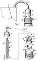
- Figure 1 is a side view of the bottle keying system of the present invention, showing the system used with replenisher bottles.
- Figure 2 is an exploded isometric view of the bottle keying system of Figure 1.
- Figure 3 is a side view of the bottle keying system of Figure 1, with portions in section, showing the system used with concentrate bottles.
- Figure 4 is an exploded isometric view of the bottle keying system of Figure 3.
- Figures 5A, 5B, 5C, 5D, 5E, and 5F are top views of the different keyholes used in one embodiment of the keying system of the present invention.
- Figure 6 is a cross-sectional view taken along line 6-6 of the concentrate bottle of Figure 4.
- Figure 7 is a side view of a protective cover for the keyed bottle covers of the present invention.
- the system of the present invention ensures the proper placement of inks into the proper plumbing system of printers such as electrophotographic machines and high resolution digital proofing machines. These printers use magenta, cyan, yellow, and black inks and sometimes use additional special colors. Generally, both a concentrate and a replenisher ink in each color is required. Each color has its own tank, valves, plumbing system, and developer. If the wrong color ink is installed into a plumbing system, the machine will not print properly, and the entire developer system must be replaced, resulting in high repair costs and long down-time periods.
- a mechanical keying system 20 prevents the bottles 10, 16 from being loaded into the wrong color plumbing system by keying each replenisher bottle 10 and concentrate bottle 16 to accept the proper matching replenisher tube 12 and concentrate tube 18.
- the keying system 20 includes unique keyed bottle covers 22 for each color which match keyed replenisher and concentrate tubes 12, 18 in the plumbing system.
- the replenisher tube 12 extends from and communicates with the tank 14.
- the replenisher tube 12 has a small orifice 24 to prevent air from entering the lines and degrading the print quality when the replenisher bottles 10 are replaced.
- a circular fitting 26 is held in place on the replenisher tube 12 by a retaining ring 28.
- the fitting 26 has internal screw threads 30 (see Figure 4).
- the replenisher bottle 10 includes a body 32 and a neck 34 and is filled with ink.
- a sealing foil 36 is placed across the opening 38 at the top of the neck 34. The foil 36 prevents contamination of the ink within the replenisher bottle 10 and leakage of ink from the bottle 10 before the bottle 10 is used.
- the keyed cover 22 is placed on and becomes an integral part of the neck 34 of the replenisher bottle 10 such that the keyed cover 22 can not be removed.
- the keyed cover 22 has screw threads 40 (see Figure 4) for further securing the cover 22 onto the threaded neck 34 of the replenisher bottle 10. Permanent securing can be accomplished by various known techniques including adhesive, tape, and mechanical locking tabs.
- the sealing and the locking is performed with a double-sided, heat induction sealing foil 36.
- the foil 36 seals the replenisher bottle 10 closed and seals the keyed cover 22 to the bottle 10.
- the keyed cover 22 can be molded in colors to match the ink in the replenishing bottle 10 to provide an additional, visual confirmation that the correct bottle 10 is being used and that the correct cover 22 is being used when the bottles 10 are filled.
- a standard threaded cover 42 is screwed onto the neck 44 of the keyed cover 22 to prevent damage to the foil 36 during shipping and storage, as shown in Figure 7.
- the standard cover 42 is removed.
- the replenisher tube 12 is inserted into the replenisher bottle 10 through the keyed cover 22. If the replenisher bottle 10 and replenisher tube 12 mate, the external shape of the tube 12 will match and be received in the keyed opening 46 in the keyed cover 22, as best shown in Figure 2.
- the end of the replenisher tube 12 is beveled to a relatively narrow point 48 to puncture the foil 36 and push the foil 36 out of the way of the tube 12 during insertion of the replenisher tube 12 into the replenisher bottle 10.
- the fitting 26 will fit over and be screwed onto the neck 44 of the keyed cover 22 on the replenisher bottle 10. If the wrong bottle 10 is attempted to be placed on the tube 12, the tube 12 will only insert into the bottle 10 a short distance, d 1 , shown in Figure 2. This will not break the foil 36 and no color contamination will occur.
- the concentrate system is similar to the replenisher system.
- the concentrate tube 18 extends from and communicates with the tank 14, and preferably, is fixed to the tank 14 via the circular fitting 26.
- the circular fitting 26 is slid over and fixed on the concentrate tube 18 and is held in place by a retaining ring 28.
- the circular fitting 26 is screw threaded onto the tank 14 opening with threads 49 on the fitting 26 and threads 50 on the tank 14.
- the concentrate bottle 16 is smaller than the replenisher bottle 10 and includes a body 52 and a neck 54 and is filled with ink.
- a sealing foil 36 is placed across the opening at the top of the neck 54 to prevent contamination of the ink within and leakage of ink from the concentrate bottle 16 before the bottle 16 is used.
- a keyed cover 22 is placed on and becomes an integral part of the neck 54 of the concentrate bottle 16 such that the keyed cover 22 can not be removed.
- the keyed cover 22 has screw threads 40 for further securing the cover 22 onto the threaded neck 54 of the concentrate bottle 16. Permanent securing can be accomplished by the methods described above with respect to the replenisher bottle 10.
- the keyed cover 22 also can be molded in colors to match the ink in the concentrate bottle 16.
- a standard cover 42 is screwed onto the neck 44 of the keyed cover 22 to prevent damage to the foil 36, as shown in Figure 7.
- the standard cover 42 is removed.
- the keyed cover 22 of the concentrate bottle 16 is placed over the concentrate tube 18. If the concentrate bottle 16 and concentrate tube 18 mate, the external shape of the tube 18 will be received in the keyed opening 46 in the keyed cover 22, and the concentrate bottle 16 will reach the internal threads 30 of the fitting 26. The fitting 26 will fit over and be screwed on the neck 44 of the keyed cover 22. If the wrong bottle 16 is attempted to be placed on the tube 18, the tube 18 will only insert into the bottle 16 a short distance, d 2 shown in Figure 4, insufficient to break the foil 36 and cause color contamination.
- Screwing the concentrate bottle 16 into the fitting 26 breaks the foil 36 and permits the ink to be drained into the tank 14. Holes 56 in the side of the concentrate tube 18 improve venting and permit the concentrate bottle 16 to drain completely. Due to the small clearances for the concentrate bottle 16, the concentrate tube 18 must be relatively short. Simply inserting the concentrate tube 18 into the concentrate bottle 16 can not guarantee that the foil 36 will be adequately broken and moved away from the concentrate tube 18 orifice 58. Thus, the circular edge 60 of the concentrate tube 18 is serrated 62 around most of the circumference to cut the foil 36. The unserrated portion 64 does not cut the foil 36 and permits the uncut portion of the foil 36 to serve as a hinge 66 around which the cut portion of the foil 36 bends out of the way of the orifice 58. This is shown in Figure 6.
- the tubes 12, 18 serve as male components
- keyed bottle covers 22 serve as female components.
- Different keys 68 are formed on the tubes 12, 18 and complementarily-shaped keyways 70 are formed on the keyed cover 22 for the bottles 10, 16.
- Figures 5A - 5F illustrate the keyways for various colors.
- the respective keys (not shown) are complementarily shaped.
- a first key and keyway 71 are formed on a first tube-keyed cover pair which is used with magenta ink.
- a second key and keyway 72 are formed on a second tube-keyed cover pair which is used with cyan ink.
- a third key and keyway 73 are formed on a third tube-keyed cover pair which is used with yellow ink.
- a fourth key and keyway 74 are formed on a fourth tube-keyed cover pair which is used with black ink.
- Fifth and sixth additional keys and keyways 75, 76 are formed on fifth and sixth tube-keyed cover pairs, which are used with additional special inks, where these inks used.
- Each key 68 and each keyway 70 include first projections 78A, 78B, respectively and second projections 80A, 80B, respectively, extending from a circular shape 82.
- the first projection 78 is located in a reference position which is identical in all keys 68 and keyways 70.
- the second projection 80 is located a predetermined rotational distance from the reference position as measured from the center of the components. This distance for each tube-keyed cover pair is selected to identify the particular tube-keyed cover pair.
- the second projection 80 on any tube-keyed cover pair is located a multiple of 45° from the location of the first projection 78 as well as from the location of the second projection 80 on any other tube-keyed cover pair.
- the first projection 78 is larger than the second projection 80.
- the shape of the first and second projections 78, 80 can differ or the projections can be identical.
- the keyed covers 22 and fittings 26 can be designed such that they work with both the replenisher and concentrate systems. This reduces tooling and part costs.
- the replenisher and concentrate bottles 10, 16 can not be incorrectly interchanged even with identical keyed covers 22 and fittings 26 due to the sizes of the components and the geometry of the hardware within the printer.
- the foil 36 can be broken, such as when the concentrate bottle 16 is attempted to be mounted on the replenisher tube 12, the keying system 20 prevents cross-color contamination.
- the keyed covers 22 can be used with existing replenisher and concentrate bottles 10, 16 to retrofit these bottles to prevent color contamination. As discussed above, the keyed covers 22 can simply thread onto the threaded necks 34, 54 of existing bottles 10, 16. The keyed cover 22 having a keyway 70 is placed on the neck 34, 54 of each bottle 10, 16, and a replenisher tube 12 or concentrate tube 18, having a key 68, replaces the existing tube. A circular fitting 26 is fixed on each tube 12, 18, and is screw threadable onto the keyed cover 22 to secure together respective bottles 10, 16 with tubes 12, 18.
- the external shapes of the tubes 12, 18 can be changed simply by rotating a small rib around the outer diameter of the molding core pin or by changing the core pin. This allows the mold for the keyed cover 22 to have different inserts for the various keyways 70.
- the key 68 and keyway 70 can have any of various shapes such as triangles, rectangles, and other polygons as long as the shapes for a given color match each other but do not match the shape for any other color.
- Single projection keys 68 and keyways 70 also can be used.
- the keying system can be used with any type of containers where keying is necessary and can be used with solid and other substance delivery systems.
- the keyed covers can be molded as one piece with the replenisher and concentrate bottles if no sealing foil is used.
Landscapes
- Stackable Containers (AREA)
- Details Of Rigid Or Semi-Rigid Containers (AREA)
- Containers Having Bodies Formed In One Piece (AREA)
- Loading And Unloading Of Fuel Tanks Or Ships (AREA)
- Closures For Containers (AREA)
- Wet Developing In Electrophotography (AREA)
- Electrophotography Configuration And Component (AREA)
Description
- The present invention relates to bottles which deliver material to a system such as electrophotographic printers. More particularly, the present invention relates to a system for insuring the proper placement of bottles which deliver material to a system such as electrophotographic printers.
- Electrophotographic printers, such as digital proofing and other printing machines produce single color or multicolored prints of an original document. A photoconductor film secured to a carrier member is first charged to a uniform potential to sensitize its imaging surface. The charged surface of the photoconductor film is exposed to an image of the original document, and records an electrostatic latent image corresponding to the informational areas contained within the image of the original document. The latent image is developed with liquid toners or inks. This imaging process may be repeated for each process color, with the images sequentially recorded on the photoconductor film. Typically, magenta, cyan, yellow, and black inks are the four standard colors, and additional special colors also may be used. The developed image is transferred from the photoconductor film to a print medium. Heat and pressure permanently transfer the image to the print medium to complete the process.
- Generally, both a concentrate and a replenisher ink in each color is required. Each color has its own tank, valves, plumbing, and developer. If the wrong color ink is installed into a plumbing system, the machine will not print properly and long down-time periods in the field result.
- Color coded keying systems for preventing the mismatching of components is well known. However, color coding can not prevent mismatched components from being placed together.
- Key and keyway systems also are well known. These systems are commonly known to lock caps on containers such as with drug containers to prevent easy opening. These systems also are used to maintain a proper alignment between two components. Some examples of these systems are disclosed in U.S. Patent Nos. 4,991,730 to Pehr, 4,854,459 to DeJonge, and 4,527,700 to Jupin et al. However, while these systems are known to secure together or align two components, their use for preventing the joining of two components is not documented. As discussed above, there is a need for a key-keyway system to prevent the connecting of improper components such as ink bottles to ink plumbing systems.
- US-A-4907019 discloses an ink cartridge mounting system for an ink jet printer in which there is provided a plurality of ink jet cartridges each containing a particular color. Each cartridge is located in an aperture which is defined by a distinctive keying pattern adapted to seat a particular ink cartridge for a particular color. JP-A-6337954 discloses a similar keying system to that of the US-A-4907019.
- According to a first aspect of this invention there is provided a keying system as claimed in claim 1 herein.
- According to a second aspect of this invention there is provided a keying system as claimed in claim 3 herein.
- According to a third aspect of this invention there is provided a keying system as claimed in
claim 6 herein. - Features of the invention are defined in appendant claims.
- The system of the present invention ensures the proper placement of inks into the proper plumbing system of printers such as electrophotographic machines. Placing the wrong bottle on the wrong receptacle is no longer possible. The system is used with printers that require a plurality of similarly shaped male tubes to be mounted on and received in specific female bottle openings and prevents the tubes from being mounted on incorrect bottle openings. The bottle openings can be formed in covers which fit on the bottles.
- A mechanical keying system prevents the inks from being loaded into the wrong color plumbing system. The keying system includes unique keyed bottle covers for each color. The keyed covers match keyed replenisher and concentrate tubes in the writer. Different keys are formed on the tubes and complementarily-shaped keyways are formed on the keyed cover for the bottle. A first key and keyway are formed on a first tube-keyed cover pair which involves magenta ink. A second key and keyway are formed on a second tube-keyed cover pair which involves cyan ink. Third and fourth keys and keyways are formed on third and fourth tube-keyed cover pairs which involve yellow and black ink. Additional tube-keyed cover pairs are used for additional special inks, where used.
- Each key and each keyway include first and second projections extending from a circular shape. The first projection is located in a reference position which is identical in all keys and keyways. The second projection is located a predetermined rotational distance from the reference position. This distance for each tube-keyed cover pair is selected to identify the particular tube-keyed cover pair. The second projection on any tube-keyed cover pair is located a multiple of 45° from the location of the first projection as well as the second projection on any other tube-keyed cover pair. The first projection is larger than the second projection.
- Figure 1 is a side view of the bottle keying system of the present invention, showing the system used with replenisher bottles.
- Figure 2 is an exploded isometric view of the bottle keying system of Figure 1.
- Figure 3 is a side view of the bottle keying system of Figure 1, with portions in section, showing the system used with concentrate bottles.
- Figure 4 is an exploded isometric view of the bottle keying system of Figure 3.
- Figures 5A, 5B, 5C, 5D, 5E, and 5F are top views of the different keyholes used in one embodiment of the keying system of the present invention.
- Figure 6 is a cross-sectional view taken along line 6-6 of the concentrate bottle of Figure 4.
- Figure 7 is a side view of a protective cover for the keyed bottle covers of the present invention.
- The system of the present invention ensures the proper placement of inks into the proper plumbing system of printers such as electrophotographic machines and high resolution digital proofing machines. These printers use magenta, cyan, yellow, and black inks and sometimes use additional special colors. Generally, both a concentrate and a replenisher ink in each color is required. Each color has its own tank, valves, plumbing system, and developer. If the wrong color ink is installed into a plumbing system, the machine will not print properly, and the entire developer system must be replaced, resulting in high repair costs and long down-time periods.
- To dispense the ink, these machines require a plurality of similarly-
shaped replenisher bottles 10, or other containers, which each are connected to areplenisher tube 12 which leads into arespective tank 14. The replenisher bottles 10 dispense ink into therespective ink tanks 14 during printing to replenish and regulate the density of the ink supply. Additionally, a plurality of similarly-shapedconcentrate bottles 16, or other containers, dispense ink into therespective tanks 14 through aconcentrate tube 18 at the beginning of printing. Amechanical keying system 20 prevents thebottles replenisher bottle 10 and concentratebottle 16 to accept the propermatching replenisher tube 12 and concentratetube 18. The keyingsystem 20 includes unique keyed bottle covers 22 for each color which match keyed replenisher and concentratetubes - Turning first to the replenisher system, as shown in Figures 1 and 2, the
replenisher tube 12 extends from and communicates with thetank 14. Thereplenisher tube 12 has asmall orifice 24 to prevent air from entering the lines and degrading the print quality when thereplenisher bottles 10 are replaced. Acircular fitting 26 is held in place on thereplenisher tube 12 by a retainingring 28. The fitting 26 has internal screw threads 30 (see Figure 4). Thereplenisher bottle 10 includes abody 32 and aneck 34 and is filled with ink. A sealingfoil 36 is placed across theopening 38 at the top of theneck 34. Thefoil 36 prevents contamination of the ink within thereplenisher bottle 10 and leakage of ink from thebottle 10 before thebottle 10 is used. - The
keyed cover 22 is placed on and becomes an integral part of theneck 34 of thereplenisher bottle 10 such that thekeyed cover 22 can not be removed. Thekeyed cover 22 has screw threads 40 (see Figure 4) for further securing thecover 22 onto the threadedneck 34 of thereplenisher bottle 10. Permanent securing can be accomplished by various known techniques including adhesive, tape, and mechanical locking tabs. In one embodiment, the sealing and the locking is performed with a double-sided, heatinduction sealing foil 36. Thus, thefoil 36 seals thereplenisher bottle 10 closed and seals thekeyed cover 22 to thebottle 10. Thekeyed cover 22 can be molded in colors to match the ink in the replenishingbottle 10 to provide an additional, visual confirmation that thecorrect bottle 10 is being used and that thecorrect cover 22 is being used when thebottles 10 are filled. A standard threadedcover 42 is screwed onto theneck 44 of thekeyed cover 22 to prevent damage to thefoil 36 during shipping and storage, as shown in Figure 7. - When the
replenisher bottle 10 is to be connected to thereplenisher tube 12, thestandard cover 42 is removed. Thereplenisher tube 12 is inserted into thereplenisher bottle 10 through thekeyed cover 22. If thereplenisher bottle 10 andreplenisher tube 12 mate, the external shape of thetube 12 will match and be received in the keyed opening 46 in thekeyed cover 22, as best shown in Figure 2. The end of thereplenisher tube 12 is beveled to a relativelynarrow point 48 to puncture thefoil 36 and push thefoil 36 out of the way of thetube 12 during insertion of thereplenisher tube 12 into thereplenisher bottle 10. Also, the fitting 26 will fit over and be screwed onto theneck 44 of thekeyed cover 22 on thereplenisher bottle 10. If thewrong bottle 10 is attempted to be placed on thetube 12, thetube 12 will only insert into the bottle 10 a short distance, d1, shown in Figure 2. This will not break thefoil 36 and no color contamination will occur. - The concentrate system, as shown in Figures 3 and 4, is similar to the replenisher system. The
concentrate tube 18 extends from and communicates with thetank 14, and preferably, is fixed to thetank 14 via thecircular fitting 26. Thecircular fitting 26 is slid over and fixed on theconcentrate tube 18 and is held in place by a retainingring 28. Thecircular fitting 26 is screw threaded onto thetank 14 opening withthreads 49 on the fitting 26 andthreads 50 on thetank 14. Theconcentrate bottle 16 is smaller than thereplenisher bottle 10 and includes abody 52 and aneck 54 and is filled with ink. A sealingfoil 36 is placed across the opening at the top of theneck 54 to prevent contamination of the ink within and leakage of ink from theconcentrate bottle 16 before thebottle 16 is used. - A
keyed cover 22 is placed on and becomes an integral part of theneck 54 of theconcentrate bottle 16 such that thekeyed cover 22 can not be removed. Thekeyed cover 22 hasscrew threads 40 for further securing thecover 22 onto the threadedneck 54 of theconcentrate bottle 16. Permanent securing can be accomplished by the methods described above with respect to thereplenisher bottle 10. Thekeyed cover 22 also can be molded in colors to match the ink in theconcentrate bottle 16. Astandard cover 42 is screwed onto theneck 44 of thekeyed cover 22 to prevent damage to thefoil 36, as shown in Figure 7. - When the
concentrate bottle 16 is to be connected to theconcentrate tube 18, thestandard cover 42 is removed. Thekeyed cover 22 of theconcentrate bottle 16 is placed over theconcentrate tube 18. If theconcentrate bottle 16 and concentratetube 18 mate, the external shape of thetube 18 will be received in the keyed opening 46 in thekeyed cover 22, and theconcentrate bottle 16 will reach theinternal threads 30 of the fitting 26. The fitting 26 will fit over and be screwed on theneck 44 of thekeyed cover 22. If thewrong bottle 16 is attempted to be placed on thetube 18, thetube 18 will only insert into the bottle 16 a short distance, d2 shown in Figure 4, insufficient to break thefoil 36 and cause color contamination. - Screwing the
concentrate bottle 16 into the fitting 26 breaks thefoil 36 and permits the ink to be drained into thetank 14.Holes 56 in the side of theconcentrate tube 18 improve venting and permit theconcentrate bottle 16 to drain completely. Due to the small clearances for theconcentrate bottle 16, theconcentrate tube 18 must be relatively short. Simply inserting theconcentrate tube 18 into theconcentrate bottle 16 can not guarantee that thefoil 36 will be adequately broken and moved away from theconcentrate tube 18orifice 58. Thus, the circular edge 60 of theconcentrate tube 18 is serrated 62 around most of the circumference to cut thefoil 36. Theunserrated portion 64 does not cut thefoil 36 and permits the uncut portion of thefoil 36 to serve as ahinge 66 around which the cut portion of thefoil 36 bends out of the way of theorifice 58. This is shown in Figure 6. - In the
keying system 20, thetubes Different keys 68 are formed on thetubes keyways 70 are formed on thekeyed cover 22 for thebottles keyway 71 are formed on a first tube-keyed cover pair which is used with magenta ink. A second key andkeyway 72 are formed on a second tube-keyed cover pair which is used with cyan ink. A third key and keyway 73 are formed on a third tube-keyed cover pair which is used with yellow ink. A fourth key andkeyway 74 are formed on a fourth tube-keyed cover pair which is used with black ink. Fifth and sixth additional keys andkeyways - Each key 68 and each
keyway 70 includefirst projections second projections circular shape 82. The first projection 78 is located in a reference position which is identical in allkeys 68 andkeyways 70. The second projection 80 is located a predetermined rotational distance from the reference position as measured from the center of the components. This distance for each tube-keyed cover pair is selected to identify the particular tube-keyed cover pair. As shown, the second projection 80 on any tube-keyed cover pair is located a multiple of 45° from the location of the first projection 78 as well as from the location of the second projection 80 on any other tube-keyed cover pair. In the illustrated embodiment, the first projection 78 is larger than the second projection 80. Alternatively, the shape of the first and second projections 78, 80 can differ or the projections can be identical. - The keyed covers 22 and
fittings 26 can be designed such that they work with both the replenisher and concentrate systems. This reduces tooling and part costs. The replenisher and concentratebottles fittings 26 due to the sizes of the components and the geometry of the hardware within the printer. Although thefoil 36 can be broken, such as when theconcentrate bottle 16 is attempted to be mounted on thereplenisher tube 12, the keyingsystem 20 prevents cross-color contamination. - The keyed covers 22 can be used with existing replenisher and concentrate
bottles necks bottles keyed cover 22 having akeyway 70 is placed on theneck bottle replenisher tube 12 or concentratetube 18, having a key 68, replaces the existing tube. Acircular fitting 26 is fixed on eachtube keyed cover 22 to secure togetherrespective bottles tubes - In molding the components of this
keying system 20, the external shapes of thetubes keyed cover 22 to have different inserts for thevarious keyways 70. Additionally, in alternative embodiments, the key 68 andkeyway 70 can have any of various shapes such as triangles, rectangles, and other polygons as long as the shapes for a given color match each other but do not match the shape for any other color.Single projection keys 68 andkeyways 70 also can be used. - Various changes and modifications may be effected therein by one skilled in the art without departing from the scope of the invention. For example, the keying system can be used with any type of containers where keying is necessary and can be used with solid and other substance delivery systems. Also, the keyed covers can be molded as one piece with the replenisher and concentrate bottles if no sealing foil is used.
Claims (6)
- A keying system (20) for insuring the proper placement of inks into the proper respective plumbing system of a printing apparatus which uses differently colored inks, wherein the printing apparatus includes an ink tank (14) for each colored ink; a plurality of similarly-shaped replenisher bottles (10), one for each color, each having a threaded neck (34) which bottles (10) dispense ink into respective tanks, and a plurality of replenisher tubes (12) over which respective replenisher bottles are mounted which lead into the respective tanks, the keying system comprising:a key (68) adapted to be formed on each replenisher tube;a threaded keyed cover (22) having a keyway (70) adapted to be screw threaded on the neck of each replenisher bottle, wherein the respective keys and keyways for each color are complementarily-shaped and are shaped differently from the keys and the keyways on other tubes and keyed covers, and wherein the keyed cover has a neck;a circular fitting (26) adapted to be fixed on the replenisher tube wherein the fitting is screw threaded onto the keyed cover to secure together the bottle and the tube; anda standard cover (42) adapted to be screw threaded onto the neck of the replenisher bottle keyed cover.
- The keying system of claim 1 further comprising a sealing and locking foil (36) adapted to be placed across the opening at the top of the neck of each replenisher bottle.
- A keying system (20) for insuring the proper placement of inks into the proper respective plumbing system of a printing apparatus which uses differently colored inks, wherein the printing apparatus includes an ink tank (14) for each colored ink, a plurality of similarly-shaped concentrate bottles (16), one for each color, each having a threaded neck (54) which bottles (16) dispense ink into respective tanks, and a plurality of concentrate tubes (18) through which respective concentrate bottles dispense ink, the keying system comprising:a key (68) adapted to be formed on each concentrate tube;a threaded keyed cover (22) having a keyway (70) adapted to be screw threaded on the neck of the concentrate bottle, wherein the respective keys and keyways for each color are complementarily-shaped and are shaped differently from the keys and the keyways on other tubes and keyed covers, wherein the keyed cover has a neck;a circular fitting (26) adapted to be slid over the concentrate tube wherein the fitting is screw threaded onto the keyed cover to secure together the bottle and the tube; anda standard cover (42) adapted to be screw threaded onto the neck of the concentrate bottle keyed cover.
- The keying system of claim 3 further comprising a sealing and locking foil (36) adapted to be placed across the opening at the top of the neck of each concentrate bottle.
- The keying system of claim 4 wherein the printing apparatus further includes a plurality of similarly-shaped replenisher bottles (10), one for each color, each having a threaded neck which bottles (10) dispense ink into respective tanks, and a plurality of replenisher tubes (12) over which respective replenisher bottles are mounted which lead into the respective tanks, wherein the keying system further comprises:a circular fitting (26) adapted to be fixed on the replenisher tube;a key (68) adapted to be formed on each replenisher tube;a threaded keyed cover (22) having a keyway (70) adapted to be screw threaded on the neck of each replenisher bottle, wherein the respective keys and keyways for each color are complementarily-shaped and are shaped differently from the keys and the keyways on other tubes and keyed covers;a standard cover (42) adapted to be screw threaded onto the neck of the replenisher bottle keyed cover; anda sealing and locking foil (36) adapted to be placed across the opening at the top of the neck of each replenisher bottle.
- A keying system for retrofitting on an existing plumbing system of a printing apparatus which uses differently colored inks, for insuring the proper placement of inks into the proper respective plumbing system, wherein the printing apparatus includes an ink tank (14) for each colored ink, a plurality of similarly-shaped replenisher bottles (10), one for each color, each having a threaded neck (34) which replenisher bottles (10) dispense ink into the respective tanks, a plurality of replenisher tubes (12) over which respective replenisher bottles are mounted which lead into the respective tanks, a plurality of similarly-shaped concentrate bottles (16), one for each color, each having a threaded neck (54) which concentrate bottles (16) dispense ink into the respective tanks, and a plurality of concentrate tubes (18) through which respective concentrate bottles dispense ink, the keying system comprising:a replenisher tube (12) for insertion into each replenisher bottle (10) to provide a passageway for substance in the replenisher bottle to the plumbing system;a key (68) adapted to be formed on each replenisher tube;a threaded keyed cover (22) having a keyway (70) adapted to be screw threaded on the neck of each replenisher bottle, wherein the respective keys and keyways for each replenisher tube-replenisher bottle pair are complementarily-shaped and are shaped differently from the keys and the keyways on other replenisher tubes and keyed covers such that the replenisher tube is receivable within only the respective replenisher bottle;a circular fitting (26) fixed on each replenisher tube, wherein the fitting is screw threaded onto the keyed cover to secure together the replenisher bottle and replenisher tube;a concentrate tube (18) for insertion into each concentrate bottle to provide a passageway for substance in the concentrate bottle to the plumbing system;a key (68) adapted to be formed on each concentrate tube;a threaded keyed cover (22) having a keyway (70) adapted to be screw threaded on the neck of each concentrate bottle, wherein the respective keys and keyways for each concentrate tube-concentrate bottle pair are complementarily-shaped and are shaped differently from the keys and the keyways on other concentrate tubes and keyed covers such that the concentrate tube is receivable within only the respective concentrate bottle; anda circular fitting (26) fixed on each concentrate tube, wherein the fitting is screw threaded onto the keyed cover to secure together the concentrate bottle and concentrate tube.
Applications Claiming Priority (2)
| Application Number | Priority Date | Filing Date | Title |
|---|---|---|---|
| US729369 | 1985-05-01 | ||
| US72936991A | 1991-07-12 | 1991-07-12 |
Publications (3)
| Publication Number | Publication Date |
|---|---|
| EP0523915A2 EP0523915A2 (en) | 1993-01-20 |
| EP0523915A3 EP0523915A3 (en) | 1993-05-26 |
| EP0523915B1 true EP0523915B1 (en) | 1996-10-16 |
Family
ID=24930728
Family Applications (1)
| Application Number | Title | Priority Date | Filing Date |
|---|---|---|---|
| EP92306306A Expired - Lifetime EP0523915B1 (en) | 1991-07-12 | 1992-07-09 | Bottle keying system |
Country Status (6)
| Country | Link |
|---|---|
| US (1) | US5293913A (en) |
| EP (1) | EP0523915B1 (en) |
| JP (1) | JPH05262394A (en) |
| AU (1) | AU1812392A (en) |
| CA (1) | CA2070941A1 (en) |
| DE (1) | DE69214544T2 (en) |
Cited By (2)
| Publication number | Priority date | Publication date | Assignee | Title |
|---|---|---|---|---|
| US6290346B1 (en) | 2000-01-05 | 2001-09-18 | Hewlett-Packard Company | Multiple bit matrix configuration for key-latched printheads |
| DE19829471B4 (en) * | 1998-02-27 | 2005-03-03 | Samsung Electronics Co., Ltd., Suwon | Ink jet printer for electrophotographic wet printer |
Families Citing this family (94)
| Publication number | Priority date | Publication date | Assignee | Title |
|---|---|---|---|---|
| US5874976A (en) * | 1996-10-07 | 1999-02-23 | Hewlett-Packard Company | Inkjet cartridge fill port adapter |
| GB9205870D0 (en) * | 1992-03-18 | 1992-04-29 | Willett Int Ltd | Replenishment of reservoirs |
| TW240299B (en) * | 1992-12-30 | 1995-02-11 | Ricoh Kk | |
| CA2144494C (en) * | 1994-03-31 | 2000-02-15 | Clark E. Harris | Valve assemblage and method of use |
| NL9400563A (en) * | 1994-04-08 | 1995-11-01 | Micro Image Technology Ltd | Device for connecting a drain and return pipe to a vessel for liquids. |
| US5595223A (en) * | 1994-10-21 | 1997-01-21 | Mitsubishi Pencil Corporation Of America | Ink refilling assembly |
| US6188417B1 (en) * | 1994-10-31 | 2001-02-13 | Hewlett-Packard Company | Fluidic adapter for use with an inkjet print cartridge having an internal pressure regulator |
| US5530531A (en) * | 1995-03-15 | 1996-06-25 | Hewlett-Packard Company | Multiple cartridge keying apparatus |
| US5526101A (en) * | 1995-03-16 | 1996-06-11 | International Communications Materials, Inc. | Toner dispensing cartridge having a nonrotatable toner cup and a rotatable sleeve-cap |
| US5562121A (en) * | 1995-04-06 | 1996-10-08 | Allied Healthcare Products, Inc. | Gas delivery system with universal outlet |
| US6183077B1 (en) | 1995-04-27 | 2001-02-06 | Hewlett-Packard Company | Method and apparatus for keying ink supply containers |
| US5815182A (en) | 1995-12-04 | 1998-09-29 | Hewlett-Packard Company | Fluid interconnect for ink-jet pen |
| US5771053A (en) | 1995-12-04 | 1998-06-23 | Hewlett-Packard Company | Assembly for controlling ink release from a container |
| US5900895A (en) | 1995-12-04 | 1999-05-04 | Hewlett-Packard Company | Method for refilling an ink supply for an ink-jet printer |
| US5732751A (en) | 1995-12-04 | 1998-03-31 | Hewlett-Packard Company | Filling ink supply containers |
| US5847734A (en) | 1995-12-04 | 1998-12-08 | Pawlowski, Jr.; Norman E. | Air purge system for an ink-jet printer |
| WO1997045269A1 (en) * | 1996-05-29 | 1997-12-04 | Dataproducts Corporation | Ink jet printer cartridge refilling method and apparatus |
| US5762114A (en) * | 1996-06-03 | 1998-06-09 | Petersen; Marvin R. | Marine fuel overfill recovery system |
| US5832972A (en) * | 1996-07-26 | 1998-11-10 | Ecolab Inc. | Dilution dispensing system with product lock-out |
| AU129937S (en) | 1996-07-12 | 1997-05-12 | Fullmark Private Ltd | Refill device for ink jet cartridges |
| US6113229A (en) * | 1996-10-07 | 2000-09-05 | Hewlett-Packard Company | Interchangeable fluid interconnect attachment and interface |
| AU5047198A (en) * | 1996-10-22 | 1998-05-15 | Bericap Gmbh & Co. Kg | Container with a built in spout |
| JP3545919B2 (en) * | 1996-10-22 | 2004-07-21 | 株式会社リコー | Toner supply container, image forming apparatus, and method of recycling and using parts constituting toner supply container |
| USD385494S (en) * | 1996-11-06 | 1997-10-28 | Ecolab Inc. | Bottle |
| USD387285S (en) * | 1996-11-06 | 1997-12-09 | Ecolab Inc. | Bottle |
| US5915427A (en) * | 1996-12-11 | 1999-06-29 | Abbott Laboratories | Anesthetic vaporizer draining system |
| US5875921A (en) * | 1997-03-12 | 1999-03-02 | Now Technologies, Inc. | Liquid chemical dispensing system with sensor |
| US6079823A (en) * | 1997-07-23 | 2000-06-27 | Marconi Data Systems Inc. | Ink bottle with puncturable diaphragm closure |
| US5937920A (en) * | 1997-08-04 | 1999-08-17 | Link Research & Development, Inc. | Product dispensing system |
| US6145967A (en) * | 1997-10-24 | 2000-11-14 | Hewlett-Packard Company | Method and apparatus for configuring a fluid interconnect for an ink-jet printhead |
| US6006046A (en) * | 1998-03-19 | 1999-12-21 | Troy Systems, Inc. | Policing key for a toner consuming machine |
| AU4702999A (en) | 1998-06-24 | 2000-01-10 | Hill-Rom, Inc. | Gas outlet barrel retention apparatus |
| US6041805A (en) * | 1998-07-07 | 2000-03-28 | Imation Corp. | Valve assembly for a removable ink cartridge |
| US5970273A (en) * | 1998-07-07 | 1999-10-19 | Imation Corp. | Ink cartridge for liquid electrographic imaging devices |
| US6109480A (en) * | 1998-07-27 | 2000-08-29 | Ecolab Inc. | Liquid dispenser and docking station for mating container |
| US6612619B2 (en) * | 1999-01-05 | 2003-09-02 | Martin H. Wieder | Quick coupler retention clip and method |
| USD467492S1 (en) | 1999-01-05 | 2002-12-24 | Martin Technology Group | Retainer clip |
| US6142194A (en) * | 1999-03-09 | 2000-11-07 | Cla-Val | Pressure fuel servicing nozzle |
| US6266506B1 (en) * | 1999-09-29 | 2001-07-24 | Xerox Corporation | Mechanical keying concept for refillable print cartridge/toner bottle strategy |
| US6164768A (en) * | 1999-11-09 | 2000-12-26 | Illinois Tool Works Inc. | Adapter and mating bottle cap for coupling bottles to ink supplies |
| US6209995B1 (en) * | 1999-11-22 | 2001-04-03 | Mitsubishi Chemical America, Inc. | Ink reservoir, ink reservoir refill container, and ink refill process |
| FR2816241B1 (en) * | 2000-11-07 | 2003-03-28 | Segepar | NON-RETURN SYSTEM FOR INK SUPPLY CIRCUIT AND INK CARTRIDGE |
| US6457899B1 (en) * | 2001-02-12 | 2002-10-01 | Youth Toy Enterprise Co., Ltd. | Union for butting two plastic bottles reused as teaching aid |
| US6554402B2 (en) * | 2001-08-16 | 2003-04-29 | Eastman Kodak Company | Ink cartridge with color discrimination structure |
| FR2831855B1 (en) * | 2001-11-06 | 2004-04-02 | Gemplus Card Int | ARRANGEMENT FOR SUPPLYING A FLUID TO A MACHINE COMPRISING FALLING MEANS |
| US6585016B1 (en) * | 2002-03-15 | 2003-07-01 | Datex-Ohmeda, Inc. | Keyed anesthetic vaporizer filling system |
| US6705713B2 (en) | 2002-07-18 | 2004-03-16 | Eastman Kodak Company | Disposable ink assemblage |
| US6715864B2 (en) * | 2002-07-18 | 2004-04-06 | Eastman Kodak Company | Disposable ink supply bag having connector-fitting |
| US6712459B2 (en) | 2002-07-18 | 2004-03-30 | Eastman Kodak Company | Ink cartridge having shielded pocket for memory chip |
| US6702435B2 (en) | 2002-07-18 | 2004-03-09 | Eastman Kodak Company | Ink cartridge having ink identifier oriented to provide ink identification |
| US20040012660A1 (en) * | 2002-07-18 | 2004-01-22 | Eastman Kodak Company | Ink cartridge having connectable-disconnectable housing and ink supply bag |
| US6709093B2 (en) | 2002-08-08 | 2004-03-23 | Eastman Kodak Company | Ink cartridge in which ink supply bag held fast to housing |
| US6755501B2 (en) | 2002-08-08 | 2004-06-29 | Eastman Kodak Company | Alternative ink/cleaner cartridge |
| US6830323B2 (en) | 2002-08-13 | 2004-12-14 | Eastman Kodak Company | Restricting flash spread when welding housing halves of cartridge together |
| US6837576B2 (en) | 2002-08-21 | 2005-01-04 | Eastman Kodak Company | Method of filling ink supply bag for ink cartridge |
| US6705714B1 (en) | 2002-08-21 | 2004-03-16 | Eastman Kodak Company | Ink cartridge having ink supply bag filled to less than capacity and folded in cartridge housing |
| US6854494B2 (en) * | 2002-10-31 | 2005-02-15 | Eastman Kodak Company | Cup and probe assembly for use in a valve system for transferring a liquid between two sources |
| US6885840B2 (en) * | 2003-06-25 | 2005-04-26 | General Plastic Industrial Co., Ltd. | Toner container and a removable lid for use therewith |
| US7004564B2 (en) * | 2003-07-31 | 2006-02-28 | Hewlett-Packard Development Company, L.P. | Printing-fluid container |
| EP1920937A3 (en) * | 2004-01-09 | 2009-03-11 | Videojet Technologies Inc. | System and method for connecting an ink bottle to an ink reservoir of an ink jet printing system |
| US7543920B2 (en) | 2004-01-09 | 2009-06-09 | Videojet Technologies Inc. | System and method for connecting an ink bottle to an ink reservoir of an ink jet printing system |
| WO2006093472A1 (en) * | 2005-03-03 | 2006-09-08 | Inke Pte Ltd | Ink reservoir |
| USD601660S1 (en) | 2006-04-14 | 2009-10-06 | Johnsondiversey, Inc. | Lock-out closure for a container with a corresponding lock-out dispenser insert |
| US8091723B2 (en) * | 2006-07-10 | 2012-01-10 | General Plastics Industrial Co., Ltd. | Removable lid for use with a toner container |
| GB0614452D0 (en) * | 2006-07-20 | 2006-08-30 | Young Peter J | Connector system |
| US20080054018A1 (en) * | 2006-08-30 | 2008-03-06 | Jeffrey James Stechschulte | Liquid dispenser with associated refill unit |
| US20080276969A1 (en) * | 2007-05-07 | 2008-11-13 | Whirlpool Corporation | Appliance with unique locking receptacles |
| WO2008151668A1 (en) * | 2007-06-13 | 2008-12-18 | Maquet Critical Care Ab | System comprising an adapter for an anesthetic equipment |
| JP2009205078A (en) | 2008-02-29 | 2009-09-10 | Brother Ind Ltd | Image forming apparatus |
| JP2009205077A (en) | 2008-02-29 | 2009-09-10 | Brother Ind Ltd | Developer cartridge and image forming apparatus |
| US8348101B2 (en) * | 2009-04-02 | 2013-01-08 | Gojo Industries, Inc. | Locking dispenser |
| US8057011B2 (en) * | 2009-05-26 | 2011-11-15 | Hewlett-Packard Development Company, L.P. | Fluid dispensing device |
| US9480789B2 (en) | 2009-06-01 | 2016-11-01 | Ethicon Endo-Surgery, Inc. | Method and sedation delivery system including a pump assembly and a co-formulation of first and second drugs |
| US9242042B2 (en) * | 2009-07-21 | 2016-01-26 | Ethicon Endo-Surgery, Inc. | Drug delivery system including a drug-container holder and a pump assembly |
| BR112012006268A2 (en) * | 2009-09-21 | 2017-05-23 | Novo Nordisk As | drug delivery system and lid function device |
| AU2010246526B2 (en) * | 2009-12-14 | 2016-08-11 | ProMinent Fluid Controls Pty Ltd | A device facilitating transfer of a substance |
| US20120103470A1 (en) * | 2010-10-28 | 2012-05-03 | Robert Terwilliger | Fluid safety dispenser |
| US20120104054A1 (en) * | 2010-10-28 | 2012-05-03 | Robert Terwilliger | Fluid safety dispenser |
| US20120103469A1 (en) * | 2010-10-28 | 2012-05-03 | Robert Terwilliger | Spring loaded fluid safety dispenser system |
| EP2447207A1 (en) | 2010-10-29 | 2012-05-02 | AB InBev NV | Dispensing appliance provided with means for positionning a container |
| JP5760399B2 (en) * | 2010-11-16 | 2015-08-12 | セイコーエプソン株式会社 | Liquid refill container |
| MX347668B (en) * | 2011-11-10 | 2017-05-08 | Solvay | An adapter assembly and a process for supplying a sterilant to a packaging system for cleaning and filling of packages. |
| US9339773B2 (en) * | 2012-01-31 | 2016-05-17 | Hydra-Flex, Inc. | Chemical dispensing apparatus and related methods |
| US9296212B2 (en) * | 2012-11-29 | 2016-03-29 | Hewlett-Packard Development Company, L.P. | Ink tank parts |
| EP3197607B1 (en) * | 2014-09-23 | 2021-10-20 | Sika Technology AG | Head plate device, storage container device, cartridge arrangement, dispensing apparatus, and their usage |
| GB201608603D0 (en) * | 2016-05-16 | 2016-06-29 | Medical Device Creations Ltd | Improved fluid line connector device |
| JP7257852B2 (en) * | 2019-03-29 | 2023-04-14 | 株式会社ダイゾー | Method for manufacturing pressurized products |
| JP7419636B2 (en) * | 2018-07-18 | 2024-01-23 | 株式会社ダイゾー | Double pressurized container, discharge product, discharge member, discharge device, and dispenser system using the same |
| US11603257B2 (en) | 2018-07-18 | 2023-03-14 | Daizo Corporation | Double pressurized container, discharge product, discharge member, dispenser system and manufacturing method for discharge product |
| WO2020017617A1 (en) * | 2018-07-18 | 2020-01-23 | 株式会社ダイゾー | Double pressurized container, discharge product, discharge member, dispenser system and manufacturing method for discharge product |
| JP7183656B2 (en) * | 2018-09-21 | 2022-12-06 | セイコーエプソン株式会社 | ink supply container |
| US10912914B2 (en) | 2019-06-06 | 2021-02-09 | GE Precision Healthcare LLC | Systems and methods for bottle retention |
| US11898700B2 (en) * | 2022-03-07 | 2024-02-13 | Suburban Manufacturing, Llc | Machine lubrication system |
| JP7854422B2 (en) * | 2023-12-13 | 2026-05-01 | 日本電子株式会社 | liquid supply device |
Family Cites Families (19)
| Publication number | Priority date | Publication date | Assignee | Title |
|---|---|---|---|---|
| US3287031A (en) * | 1964-09-21 | 1966-11-22 | William H Simmons | Indexed keyed connection |
| US3563267A (en) * | 1968-09-30 | 1971-02-16 | Air Reduction | Gas dispensing double check valve construction |
| BE755282A (en) * | 1969-09-02 | 1971-02-01 | Eastman Kodak Co | POWER SUPPLY DEVICE WITH LIQUID ELECTROGRAPHIC DEVELOPER AND DEVELOPMENT ELECTROGRAPHIC STATION POWERED BY SUCH A DEVICE |
| GB1455885A (en) * | 1973-12-21 | 1976-11-17 | Xerox Corp | Liquid dispensing |
| FR2413604A1 (en) * | 1978-01-03 | 1979-07-27 | Convers Stephane | Self-service filling station dispenser nozzle - has selector union to prevent user from filling his tank with wrong fuel |
| US4211439A (en) * | 1978-07-26 | 1980-07-08 | Moldestad Jon P | Safety device for hose connections |
| GB2116274A (en) * | 1982-02-26 | 1983-09-21 | Sozaburo Maeshiba | Prevention of accidental mixing of different kinds of oils |
| US4740808A (en) * | 1983-01-08 | 1988-04-26 | Canon Kabushiki Kaisha | Developer container and a developing apparatus usable with the same |
| US4718699A (en) * | 1983-02-14 | 1988-01-12 | Allied Healthcare Products, Inc. | Gas system outlet station assembly |
| FR2546484B2 (en) * | 1983-03-07 | 1986-05-09 | Cebal | CONTAINER WITH TAMPER-RESISTANT FLIPPABLE SKIRT WITH INTERIOR CAP |
| JPS61180158A (en) * | 1985-01-09 | 1986-08-12 | Hitachi Electronics Eng Co Ltd | Inspection system for flopy recording medium |
| US4860050A (en) * | 1986-07-28 | 1989-08-22 | Ricoh Company, Ltd. | Developing replenisher material for use in image forming device |
| DE3633606A1 (en) * | 1986-10-02 | 1988-04-14 | Siemens Ag | MULTIFUNCTIONAL TONER CONTAINER FOR NON-MECHANICAL PRINTING AND COPYING MACHINES |
| US4853708A (en) * | 1988-03-03 | 1989-08-01 | Eastman Kodak Company | Ink cartridge and housing construction for multicolor ink jet printing apparatus |
| US4854459A (en) * | 1988-11-18 | 1989-08-08 | Primary Delivery Systems, Inc. | Convertible childproof/non-childproof cap and container |
| JPH0738089B2 (en) * | 1988-11-30 | 1995-04-26 | 三田工業株式会社 | Developer container |
| US4907019A (en) * | 1989-03-27 | 1990-03-06 | Tektronix, Inc. | Ink jet cartridges and ink cartridge mounting system |
| JPH02310572A (en) * | 1989-05-26 | 1990-12-26 | Canon Inc | Image forming device |
| US4991730A (en) * | 1989-09-12 | 1991-02-12 | Pehr Harold T | Captive key release closure structure |
-
1992
- 1992-06-09 AU AU18123/92A patent/AU1812392A/en not_active Abandoned
- 1992-06-10 CA CA002070941A patent/CA2070941A1/en not_active Abandoned
- 1992-07-09 DE DE69214544T patent/DE69214544T2/en not_active Expired - Fee Related
- 1992-07-09 EP EP92306306A patent/EP0523915B1/en not_active Expired - Lifetime
- 1992-07-10 JP JP18343892A patent/JPH05262394A/en active Pending
-
1993
- 1993-05-27 US US08/071,219 patent/US5293913A/en not_active Expired - Fee Related
Cited By (2)
| Publication number | Priority date | Publication date | Assignee | Title |
|---|---|---|---|---|
| DE19829471B4 (en) * | 1998-02-27 | 2005-03-03 | Samsung Electronics Co., Ltd., Suwon | Ink jet printer for electrophotographic wet printer |
| US6290346B1 (en) | 2000-01-05 | 2001-09-18 | Hewlett-Packard Company | Multiple bit matrix configuration for key-latched printheads |
Also Published As
| Publication number | Publication date |
|---|---|
| DE69214544T2 (en) | 1997-04-24 |
| EP0523915A3 (en) | 1993-05-26 |
| DE69214544D1 (en) | 1996-11-21 |
| CA2070941A1 (en) | 1993-01-13 |
| AU1812392A (en) | 1993-01-14 |
| US5293913A (en) | 1994-03-15 |
| JPH05262394A (en) | 1993-10-12 |
| EP0523915A2 (en) | 1993-01-20 |
Similar Documents
| Publication | Publication Date | Title |
|---|---|---|
| EP0523915B1 (en) | Bottle keying system | |
| US6276788B1 (en) | Ink cartridge for an ink jet printer having quick disconnect valve 09 | |
| US7062205B2 (en) | Structure for locking a shutter member in a toner supplying container | |
| JP6661462B2 (en) | Liquid ejection device and liquid supply container | |
| EP0878307B1 (en) | Mechanical and electrical keying arrangement for replaceable ink cartridge | |
| US6023594A (en) | Image forming apparatus having a plurality of image forming stations including devices and receiving sections for detachably receiving the devices | |
| EP1099558B1 (en) | Adapter and mating bottle cap for coupling bottles to ink supplies | |
| CN1612810B (en) | Machine fluid feed assembly including key pin device | |
| US4740808A (en) | Developer container and a developing apparatus usable with the same | |
| EP0395197B1 (en) | Ink jet cartridges and ink cartridge mounting system | |
| EP2009510B1 (en) | Toner cartridge locking apparatus, image forming apparatus having the same, toner cartridge, and mounting and dismounting method for a toner cartridge | |
| US4611899A (en) | Developing apparatus | |
| US12208622B2 (en) | Liquid supplying system including tank and liquid bottle connectable to the tank | |
| TWI765682B (en) | ink supply container | |
| US11701890B2 (en) | Liquid storage container | |
| EP0852182B1 (en) | Ink Ribbon cartridge | |
| EP1312480B1 (en) | Supply cartridge for a printing apparatus | |
| JPS634953A (en) | Ink supply apparatus | |
| JP2009098409A (en) | Color image forming apparatus | |
| US9211720B2 (en) | Fluid container having first and second key set | |
| CN115723437A (en) | Liquid storage bottle and liquid supply device | |
| EP3988316B1 (en) | Ink refilling container | |
| US20160223943A1 (en) | Developer container, image forming unit, and image forming apparatus | |
| US20030165347A1 (en) | Color image forming apparatus | |
| US6438328B1 (en) | Reversible shutter lockout feature |
Legal Events
| Date | Code | Title | Description |
|---|---|---|---|
| PUAI | Public reference made under article 153(3) epc to a published international application that has entered the european phase |
Free format text: ORIGINAL CODE: 0009012 |
|
| AK | Designated contracting states |
Kind code of ref document: A2 Designated state(s): BE DE FR GB IT NL |
|
| PUAL | Search report despatched |
Free format text: ORIGINAL CODE: 0009013 |
|
| AK | Designated contracting states |
Kind code of ref document: A3 Designated state(s): BE DE FR GB IT NL |
|
| 17P | Request for examination filed |
Effective date: 19931007 |
|
| 17Q | First examination report despatched |
Effective date: 19950329 |
|
| GRAG | Despatch of communication of intention to grant |
Free format text: ORIGINAL CODE: EPIDOS AGRA |
|
| GRAH | Despatch of communication of intention to grant a patent |
Free format text: ORIGINAL CODE: EPIDOS IGRA |
|
| GRAH | Despatch of communication of intention to grant a patent |
Free format text: ORIGINAL CODE: EPIDOS IGRA |
|
| GRAA | (expected) grant |
Free format text: ORIGINAL CODE: 0009210 |
|
| AK | Designated contracting states |
Kind code of ref document: B1 Designated state(s): BE DE FR GB IT NL |
|
| PG25 | Lapsed in a contracting state [announced via postgrant information from national office to epo] |
Ref country code: BE Effective date: 19961016 |
|
| REF | Corresponds to: |
Ref document number: 69214544 Country of ref document: DE Date of ref document: 19961121 |
|
| ET | Fr: translation filed | ||
| ITF | It: translation for a ep patent filed | ||
| PGFP | Annual fee paid to national office [announced via postgrant information from national office to epo] |
Ref country code: GB Payment date: 19970620 Year of fee payment: 6 |
|
| PGFP | Annual fee paid to national office [announced via postgrant information from national office to epo] |
Ref country code: FR Payment date: 19970711 Year of fee payment: 6 |
|
| PGFP | Annual fee paid to national office [announced via postgrant information from national office to epo] |
Ref country code: DE Payment date: 19970729 Year of fee payment: 6 |
|
| PLBE | No opposition filed within time limit |
Free format text: ORIGINAL CODE: 0009261 |
|
| STAA | Information on the status of an ep patent application or granted ep patent |
Free format text: STATUS: NO OPPOSITION FILED WITHIN TIME LIMIT |
|
| 26N | No opposition filed | ||
| PG25 | Lapsed in a contracting state [announced via postgrant information from national office to epo] |
Ref country code: NL Free format text: LAPSE BECAUSE OF NON-PAYMENT OF DUE FEES Effective date: 19980201 |
|
| NLV4 | Nl: lapsed or anulled due to non-payment of the annual fee |
Effective date: 19980201 |
|
| PG25 | Lapsed in a contracting state [announced via postgrant information from national office to epo] |
Ref country code: GB Free format text: LAPSE BECAUSE OF NON-PAYMENT OF DUE FEES Effective date: 19980709 |
|
| GBPC | Gb: european patent ceased through non-payment of renewal fee |
Effective date: 19980709 |
|
| PG25 | Lapsed in a contracting state [announced via postgrant information from national office to epo] |
Ref country code: FR Free format text: LAPSE BECAUSE OF NON-PAYMENT OF DUE FEES Effective date: 19990331 |
|
| PG25 | Lapsed in a contracting state [announced via postgrant information from national office to epo] |
Ref country code: DE Free format text: LAPSE BECAUSE OF NON-PAYMENT OF DUE FEES Effective date: 19990501 |
|
| REG | Reference to a national code |
Ref country code: FR Ref legal event code: ST |
|
| PG25 | Lapsed in a contracting state [announced via postgrant information from national office to epo] |
Ref country code: IT Free format text: LAPSE BECAUSE OF NON-PAYMENT OF DUE FEES Effective date: 20050709 |