EP0523646B1 - Lubricant pump for an internal combustion engine - Google Patents
Lubricant pump for an internal combustion engine Download PDFInfo
- Publication number
- EP0523646B1 EP0523646B1 EP92112052A EP92112052A EP0523646B1 EP 0523646 B1 EP0523646 B1 EP 0523646B1 EP 92112052 A EP92112052 A EP 92112052A EP 92112052 A EP92112052 A EP 92112052A EP 0523646 B1 EP0523646 B1 EP 0523646B1
- Authority
- EP
- European Patent Office
- Prior art keywords
- pump
- lubricant
- plunger
- adjusting
- stroke
- Prior art date
- Legal status (The legal status is an assumption and is not a legal conclusion. Google has not performed a legal analysis and makes no representation as to the accuracy of the status listed.)
- Expired - Lifetime
Links
- 239000000314 lubricant Substances 0.000 title claims description 101
- 238000002485 combustion reaction Methods 0.000 title claims description 9
- 238000005086 pumping Methods 0.000 claims description 31
- 230000007246 mechanism Effects 0.000 claims description 19
- 239000012530 fluid Substances 0.000 claims description 14
- 230000004044 response Effects 0.000 claims description 13
- 230000006835 compression Effects 0.000 claims description 8
- 238000007906 compression Methods 0.000 claims description 8
- 230000000670 limiting effect Effects 0.000 claims description 7
- 230000008859 change Effects 0.000 claims description 6
- 239000000463 material Substances 0.000 claims description 4
- 239000010687 lubricating oil Substances 0.000 claims description 3
- 230000007613 environmental effect Effects 0.000 claims 1
- 229920003002 synthetic resin Polymers 0.000 claims 1
- 239000000057 synthetic resin Substances 0.000 claims 1
- 230000001050 lubricating effect Effects 0.000 description 13
- 238000010276 construction Methods 0.000 description 10
- 238000005553 drilling Methods 0.000 description 5
- 229910000831 Steel Inorganic materials 0.000 description 4
- 239000010959 steel Substances 0.000 description 4
- 230000001052 transient effect Effects 0.000 description 4
- 230000000694 effects Effects 0.000 description 3
- 238000005461 lubrication Methods 0.000 description 3
- 239000003921 oil Substances 0.000 description 3
- 230000036961 partial effect Effects 0.000 description 3
- 230000002829 reductive effect Effects 0.000 description 3
- 229910000838 Al alloy Inorganic materials 0.000 description 2
- 229910052782 aluminium Inorganic materials 0.000 description 2
- XAGFODPZIPBFFR-UHFFFAOYSA-N aluminium Chemical compound [Al] XAGFODPZIPBFFR-UHFFFAOYSA-N 0.000 description 2
- 230000005484 gravity Effects 0.000 description 2
- 239000003562 lightweight material Substances 0.000 description 2
- 239000007788 liquid Substances 0.000 description 2
- 238000011068 loading method Methods 0.000 description 2
- 238000013022 venting Methods 0.000 description 2
- 241000237858 Gastropoda Species 0.000 description 1
- 101000713935 Mus musculus Tudor domain-containing protein 7 Proteins 0.000 description 1
- 230000009471 action Effects 0.000 description 1
- 238000004891 communication Methods 0.000 description 1
- 230000003247 decreasing effect Effects 0.000 description 1
- 238000006073 displacement reaction Methods 0.000 description 1
- 238000010304 firing Methods 0.000 description 1
- 239000000446 fuel Substances 0.000 description 1
- 230000006870 function Effects 0.000 description 1
- 229930195733 hydrocarbon Natural products 0.000 description 1
- 150000002430 hydrocarbons Chemical class 0.000 description 1
- 230000006698 induction Effects 0.000 description 1
- 238000004519 manufacturing process Methods 0.000 description 1
- 229910052751 metal Inorganic materials 0.000 description 1
- 239000002184 metal Substances 0.000 description 1
- 239000000203 mixture Substances 0.000 description 1
- 230000004043 responsiveness Effects 0.000 description 1
- 230000000979 retarding effect Effects 0.000 description 1
- 230000003584 silencer Effects 0.000 description 1
- 239000000779 smoke Substances 0.000 description 1
- 239000007921 spray Substances 0.000 description 1
- 238000005507 spraying Methods 0.000 description 1
Images








Classifications
-
- F—MECHANICAL ENGINEERING; LIGHTING; HEATING; WEAPONS; BLASTING
- F01—MACHINES OR ENGINES IN GENERAL; ENGINE PLANTS IN GENERAL; STEAM ENGINES
- F01M—LUBRICATING OF MACHINES OR ENGINES IN GENERAL; LUBRICATING INTERNAL COMBUSTION ENGINES; CRANKCASE VENTILATING
- F01M3/00—Lubrication specially adapted for engines with crankcase compression of fuel-air mixture or for other engines in which lubricant is contained in fuel, combustion air, or fuel-air mixture
- F01M3/02—Lubrication specially adapted for engines with crankcase compression of fuel-air mixture or for other engines in which lubricant is contained in fuel, combustion air, or fuel-air mixture with variable proportion of lubricant to fuel, lubricant to air, or lubricant to fuel-air-mixture
-
- F—MECHANICAL ENGINEERING; LIGHTING; HEATING; WEAPONS; BLASTING
- F16—ENGINEERING ELEMENTS AND UNITS; GENERAL MEASURES FOR PRODUCING AND MAINTAINING EFFECTIVE FUNCTIONING OF MACHINES OR INSTALLATIONS; THERMAL INSULATION IN GENERAL
- F16N—LUBRICATING
- F16N13/00—Lubricating-pumps
- F16N13/02—Lubricating-pumps with reciprocating piston
- F16N13/04—Adjustable reciprocating pumps
-
- F—MECHANICAL ENGINEERING; LIGHTING; HEATING; WEAPONS; BLASTING
- F02—COMBUSTION ENGINES; HOT-GAS OR COMBUSTION-PRODUCT ENGINE PLANTS
- F02B—INTERNAL-COMBUSTION PISTON ENGINES; COMBUSTION ENGINES IN GENERAL
- F02B75/00—Other engines
- F02B75/02—Engines characterised by their cycles, e.g. six-stroke
- F02B2075/022—Engines characterised by their cycles, e.g. six-stroke having less than six strokes per cycle
- F02B2075/025—Engines characterised by their cycles, e.g. six-stroke having less than six strokes per cycle two
Definitions
- the present invention relates to a lubricant pump for an internal combustion engine as claimed in the preamble portion of claim 1.
- one of the essentials comprises the supply of lubricating oil automatically with a rate appropriate to the current engine operating conditions.
- One form of lubricating system employed within internal combustion engines and particularly two cycle engines employs a reciprocating plunger type pump that is driven by the engine and supplies a finite amount of lubricant during each stroke of the pump.
- a reciprocating plunger type pump that is driven by the engine and supplies a finite amount of lubricant during each stroke of the pump.
- it is desirable to vary the output of the pump or the amount of lubricant delivered to the engine during each pump stroke so as to insure against excess lubrication and the disadvantages accompanying it. That is, it is desirable to insure against the supply of excess lubricant so as to avoid exhaust smoke and the emission of unburned hydrocarbons.
- a number of arrangements have been employed for controlling the amount of lubricant delivered to the engine during each pumping stroke.
- One way in which the amount of lubricant may be controlled is by changing the effective stroke of the plunger. This has conventionally been done in the past by providing some form of adjustable stop that cooperates with a portion of the plunger which is always exposed from the bore in which the plunger reciprocates. There are a number of disadvantages to such an arrangement.
- the quantity of lubricant delivered to the engine is normally varied in response to an engine condition, most typically engine speed.
- the conventional types of systems including those of the prior art as previously mentioned, adjust the stroke of the pump plunger in response to the setting of the speed controlling unit of the engine, such as the throttle valve. Normally this is done by providing a mechanical connection between the throttle valve or its controlling mechanism and the stop which changes the plunger stroke. As a result, these devices generally vary the amount of lubricant linearally with respect to engine speed.
- the prior art devices generally can vary the amount of lubricant only with respect to that particular condition. For example, if the control is related to the engine throttle control, then the devices generally can vary the amount of lubricant only in response to throttle control position. However, the amount of lubricant required by the engine may vary in response to other condition than merely throttle position.
- the prior art mechanisms have permitted some minor adjustment, primarily for transient conditions, they have not been able to accommodate changes in lubrication for conditions in addition to the main sensed condition.
- lubricant pumps have already been proposed wherein the pump plunger in its maximal advanced position abuts against the adjusting plunger.
- FR-A-1 400 280 shows a lubricant pump for a hydraulic press wherein the pump plunger actuated by hydraulic pressure contacts the adjusting plunger, thereby limiting the stroke of the pump plunger.
- a lubricant pump of the type described in the preamble of claim 1 is known from GB-A-2 151 313.
- the lubricant pump proposed in this document employs a pair of check valves disposed in the delivery passage and the discharge passage, respectively. Aside from the fact that these check valves increase the flow resistance for the lubricant flowing through the respective passages, they cannot control the opening and the closing of the respective passages as exactly as desired.
- this objective is performed by a lubricant pump described in claim 1.
- the invention is described in conjunction with a motorcycle application because motorcycles frequently employ two cycle internal combustion engines and this invention has particular utility in conjunction with such engines. It is to be understood, however, that the invention may be employed in lubricating systems for other types of engines or, for the matter, in lubricating systems for other types of machines.
- the engine 11 includes a cylinder block 12 having a cylinder bore 13 which is closed at one end by a cylinder head 14 and in which a piston 15 reciprocates.
- the piston 15 drives a crankshaft 16 rotatably journaled within a crankcase chamber 17 formed by the lower portion of the cylinder block 12 and a crankcase member 18 that is affixed in a suitable manner to the cylinder block.
- the engine 11 operates on the two cycle principal and is of the crankcase compression type.
- a charge is delivered to the crankcase chamber 17 from an induction system that includes a carburetor 19.
- the carburetor 19 has an intake passage 21 in which a sliding throttle piston 22 is provided.
- the throttle piston 22 is normally biased towards its idle position by means of a coil compression spring 23.
- a throttle control cable 24 is connected to a hand grip throttle control 25 by means including a connector 26.
- Air is drawn into the carburetor intake passage 21 through an air cleaner and air silencer (not shown) and flows in the direction of the arrows to an intake passage 27 formed in the cylinder block 12 and which communicates with the crankcase chamber 17 during the reciprocation of the piston 15, as is well known in this art.
- the charge which is drawn into the crankcase chamber 17 during the upward movement of the piston 15 is compressed as the piston 15 descends in the cylinder bore 13. This compressed charge is then transferred to the combustion chamber formed above the end of the piston 15 through one or more scavenge passages (not shown) in a manner well known in this art. This charge is then further compressed in the combustion chamber as the piston 15 moves upwardly and is fired by means of a spark plug 27 mounted in the cylinder head 14.
- the spark plug 27 is fired by an ignition system, indicated generally by the block 28 and which may be of any known type.
- An exhaust passage 29 is formed in the cylinder block 12 and has positioned within it an exhaust control valve 31 which is operated by means of a servo motor 32 so as to change the timing of the opening and closing of the exhaust passage 29.
- the exhaust control valve 31 is employed for retarding the opening of the exhaust port 29 under low and mid-range speeds as shown in the phantom line view of Figure 1 and to provide advanced opening of the exhaust passage 29 under high speed operation.
- a CPU 33 is provided for controlling both the servo motor 32 and the firing of the spark plug 27 by the ignition system 28.
- a engine speed and crank angle sensor indicated by the phantom line 34 inputs a signal to the ignition system 28 and the CPU 33 so as to provide a speed and crank angle position for these members. Any other inputs may be supplied to the CPU 33 for its operation such as throttle position sensors, etc.
- the invention deals primarily with the lubricating system for the engine which lubricating system is indicated generally by the reference numeral 35 and specifically to the lubricating pump therefore, indicated generally by the reference numeral 36.
- Lubricant is supplied to the lubricating pump 36 from a remote lubricant reservoir 37 in which a quantity of lubricant 38 is contained.
- the lubricant reservoir 37 is positioned vertically above the lubricant pump 36 and supplies lubricant thereto by gravity through a line 39.
- the lubricant pump 36 has a discharge fitting 41 that delivers lubricant to the engine 11 for its lubrication through a lubricant supply conduit, indicated generally by the reference numeral 42.
- the engine 11 is lubricated by spraying lubricant from the pump 36 into the intake port 27. It is to be understood, however, that the lubricant may be supplied to the engine 11 at one or more locations, as is well known in the art.
- the amount of lubricant delivered by the lubricant pump 36 is changed in response to engine operating conditions and a lubricant quantity controlling pulley 43 is associated with the lubricant pump 36 in a manner to be described so as to vary the stroke of the pump 36 and, accordingly, the amount of lubricant delivered.
- the pulley 43 is operated by means of a Bowden wire cable 44 that is connected to the connector 26.
- a wire transmitter 45 is also connected to a member 46 of the connector 26 so that the amount of lubricant supplied will be generally responsive to the position of the throttle control 25 but during transient conditions there will be some delay before the amount of lubricant supplied is changed.
- the connector 26 is of the type shown in Japanese published application 62-178707 published August 5, 1987. Of course, other types of controls for varying the position of the pulley 43 may be incorporated.
- the lubricant pump 36 will now be described in greater detail by reference to Figures 2 through 7.
- the pump assembly 36 is comprised of a main housing piece 47 which is formed from a light weight material such as aluminum or aluminum alloy.
- the housing piece 46 is provided with a flange 48 so that it can be attached to the crankcase 18 of the engine in driving relationship with the crankshaft 16, in a manner which will be described.
- the main housing piece 47 is provided with an internal cavity that is defined by a cylindrical bore 49 and a lower cavity portion 51.
- the lower cavity portion 51 is closed by means of a cover plate 52 that is affixed to the main housing 47 by means of a plurality of threaded fasteners 53.
- the upper end of the bore 49 is covered by means of a second closure plate 54 which is affixed to the main body portion 47 in a suitable manner as by fasteners 50 ( Figure 5) and which defines an internal cavity in which the pump stroke adjusting mechanism, indicated generally by the reference numeral 55, is provided.
- a sleeve 56 having a through bore 57 is rotatably journaled in the main housing bore 49.
- the sleeve 56 may also be formed from a light weight material such as aluminum or an aluminum alloy.
- the sleeve 56 is rotatably driven in the bore 49 by means of a worm gear assemblage, indicated generally by the reference numeral 58 and which includes a worm 59 that is formed integrally with a shaft 61 that has a suitable driving connection with the crankshaft 16.
- the worm 59 drives a worm wheel 62, formed from a resinous plastic material has a driving connection with the sleeve 56 which is provided for by means of a pin 63.
- the worm wheel 62 is engaged at its upper end with a shoulder 64 formed by the main housing 47 and is engaged at its lower ends by upstanding bosses 65 of the cover piece 52. In this way, the worm wheel 62 and sleeve 56 are axially positioned within the main housing assembly 47.
- the sleeve 56 has a through bore and the axis of this bore is indicated by the line 66.
- This axis 66 is coaxial with the axis of the bore 49 and a pump plunger 67 is slidably supported in the lower end of this bore.
- the pump plunger 67 has affixed to its lower end a cross pin 68 that is received in a gap 69 formed by the upstanding bosses 65 of the cover piece 52. As a result, the pump plunger 67 will be held against rotations by the bosses 65 but may reciprocated within the bore of the sleeve 56.
- Reciprocation of the pump plunger 67 is effective by means of a pair of driving cams 71 formed on the lower surface of the worm wheel 62.
- These cam surfaces 71 have a generally truncated configuration so that as the worm wheel 62 rotates, the pump plunger 67 will complete two strokes per revolution.
- a coil compression spring 72 is provided in the cover plate 52 and acts against the drive pin 68 so as to normally urge the drive pin 68 upwardly into engagement with the drive cams 71 and also to urge the pump plunger 67 to an upward position.
- the direction of rotation of the worm wheel 62 is indicated by the arrow "A" in Figure 2.
- the downward stroke of the pumping plunger 67 is controlled by the height of the driving cams 71. This will determine the bottom dead center position of the pumping plunger 67.
- the upward movement of the pumping plunger 57 is, however, controlled by the spring 72 and by the stroke adjusting mechanism 55. This stroke adjusting mechanism 55 will now be described in detail by reference primarily to Figures 2, 5 and 6.
- the stroke limiting mechanism 55 includes an adjusting plunger 73 that is slidably supported in the bore of the sleeve 56 opposite to the pumping plunger 67.
- the adjusting plunger 73 is urged by a mouse trap type spring 74 into engagement with a stroke adjusting cam 75 having a generally snail like configuration.
- the adjusting cam 75 is connected for rotation with a camshaft 76 that includes a shaft element 77 by means of a drive pin 78.
- the drive pin 78 is restrained within a bore formed in the adjusting cam 75 and a corresponding bore in the shaft 77 by means of an O ring 79. It should be noted, and as clearly shown in Figure 6, that this driving connection permits the adjusting cam 75 to be shifted transversely relative to the camshaft 77 for adjusting purposes, as will be described.
- the camshaft 77 is drivingly coupled to the pulley 43 by means of a drive pin 81.
- a torsional spring 82 is loaded between the pulley 43 and the cover plate 54 for normally urging the camshaft 77 and stroke adjusting cam 75 in a direction to force the adjusting plunger 73 to a downward, stroke limiting position.
- Direction is indicated by the arrow "B" in Figures 2 and 6.
- the extreme lower position of the adjusting plunger 73 when the cam 75 is rotated to its maximum limiting position is controlled by means of an adjusting mechanism, indicated generally by the reference numeral 83.
- This adjusting mechanism 83 includes a further shaft 84 which is journaled within a bore 85 of the cover piece 54 which bore 85 is co-axial with the axis of rotation of the shaft 77.
- the adjusting shaft 84 has an internal bore 86 which is also co-axial with this shaft and in which a pilot portion of the camshaft 77 is received.
- the adjusting shaft 84 has an eccentric portion 87 that is received within a bore 88 of the cam 75.
- the adjusting shaft 84 is locked in its adjusted position by means of a clamping plate 89 and lock screw 91 fixed in the cover plate 54.
- the conduit 39 supplies lubricant to the pump 36 from the reservoir 37.
- the lower cover plate 52 is provided with an inlet opening 92 by which fluid may flow into the chamber 51.
- a pair of vertically extending delivery passages 93 and 94 are formed in the main housing 47 ( Figure 4) which extend upwardly around the sides of the sleeve 56.
- Radially extending ports 95 and 96 are provided in the housing 47 and extend to the bore 49.
- the sleeve 56 is provided with a distributor passage 97 which will sequentially register with the supply ports 95 and 96 as the sleeve 56 rotates.
- the supply passages 95 and 96 may be easily formed by drilling through one face of the housing assembly 47 when the sleeve 56 is not in place with this drilled passageway intersecting the supply passages 93 and 94. A ball type plug 98 is then inserted into this drilling to close the passages.
- a pair of delivery passages 99 and 101 are also formed in the housing member 47 by a similar drilling that extends at ninety degrees (90°) to the drilling which forms the supply passages 95 and 96. This drilling is then closed by a ball type plug 102.
- the supply passages 99 and 101 are intersected by further passages in which supply fittings 103 and 104 are provided with ball type check valves 105 and 106 controlling the communication of the delivery passages 99 and 101 with the fittings 103 and 104, respectively. Fluid will be pumped through the passages 99 and 101 when they register with the distributor passage 97 of the sleeve 56 upon its rotation as shown by the arrows "D" in Figure 4.
- the fittings 103 and 104 cooperate with the outlet fitting 41 as previously described so as to supply the lubricant to the engine.
- the cover plate 52 ( Figure 2) is provided with a drain opening 107 which is normally closed by drain plug 108. By removing the drain plug 108 lubricant may be drained from the pump assembly 36.
- the cover plate 54 is provided with a vent opening 109 which is normally closed by a vent plug 111. Air may be bled from the pump assembly 36 by loosening the plug 111 until lubricant flows out of the vent opening 109 and then the plug 111 may be re-tightened. If the pump 36 is operated in an inverted condition, the function of the drain 108 and vent plugs 111 will obviously be reversed.
- the plungers 67 and 73, sleeve 56 and main housing member 47 are all formed from the same material, there will be no problems of different thermal expansions and the pump can be operate quite smoothly and efficiently. Also, since the sleeve 56 is constantly rotating relative to the adjusting plunger 73, the frictional resistance to adjusting movement of the adjusting plunger 73 will be reduced and the components may be quite light in weight. Also, it is possible to use a non-metallic worm wheel 62 because of the light loading and this permits all elements to be generally light weight in construction. Furthermore, since the clearance volume 77 may be substantially zero at top dead center regardless of the amount of lubricant being pumped, the device is very effective in insuring against air intrusion into the system and excellent lubricant control may be achieved.
- the pumping plunger of the lubricant pump 36 has been mechanically driven.
- the invention may also be employed with pumps of the type wherein the pumping plunger is electrically driven.
- the pump stroke limiting plunger 73 has been connected by means of a Bowden wire cable to the connector 46 of the throttle control mechanism.
- the first of these disadvantages is that the supply of lubricant varies in a generally linear fashion with respect to the position of the throttle pistons 22 and the hand throttle grip 25.
- the connector 26 permits some adjustment in the lubricant output during transient conditions but the general control is linear.
- the slope of the curve can be changed but once the slope is determined, the relationship between lubricant supply and throttle valve position is in the same ratio. This is not always desirable.
- connection from the stop plunger 73 back to the throttle control 25 gives a feedback to the operator which will interfere with the throttle feel of the control system.
- this type of mechanism does not permit adjustment in the amount of lubricant supplied in response to other conditions, such as ambient temperature.
- FIGS 8 through 13 show another embodiment of the invention wherein the disadvantages as aforenoted are avoided and yet all of the advantages of the previously described embodiments are enjoyed.
- an engine constructed in accordance with this embodiment is identified generally by the reference numeral 201.
- the basic construction of the engine 201 is the same as the engine 11 in Figure 1 and, for that reason, components of this embodiment which are the same as the previously described embodiment have been identified by the same reference numerals and will not be described again.
- the exhaust control valve 31 of the previous embodiment is not illustrated. It is to be understood, however, that such an exhaust control valve can be employed in conjunction with this embodiment.
- the general lubricating system in this embodiment is identified generally by the reference numeral 202 and includes a lubricating pump 203 which will be described in more detail by particular reference to Figures 9 through 13.
- This lubricant pump 203 receives lubricant from a lubricant reservoir 204 by gravity flow through a supply line 205.
- the lubricant in the reservoir 204 is indicated by the reference numeral 206.
- a delivery line 207 which sprays fuel into the intake passage 201 through a check valve 208 there is provided a vent line 209 which extends from the pump 203 back to the reservoir 204 above the level of the lubricant 206 therein. This vent line 209 will assist in venting air from the lubricant pump 203.
- this embodiment also, like the previously described embodiments, varies the liquid displacement of the pump 203 by a device which does not change the volume at top dead center and hence the intrusion of air into the system is minimized in the same manner as the previously described embodiments.
- the pump 203 includes an outer housing indicated generally by the reference numeral 211 which has a bore 212 that is closed at one end by a closure plug 213 having a pilot portion that is received into the bore 212 with a press fit.
- a chamber 214 is formed at the end of the bore 212 opposite the closure plug 213 and receives lubricant from the reservoir 204 through the line 205 and an internal fitting 215 formed in the housing member 211.
- a vent fitting 216 communicates the chamber 214 with the vent line 209 so that air which enters the system will be purged and returned back to the reservoir 204 through the vent line.
- the main housing 211 Adjacent the chamber 214, the main housing 211 has a pilot portion 217 that penetrates through an opening 218 formed in the crankcase member 18 and which is sealed thereto by means of an O ring seal 219.
- This pilot portion 217 is formed with a bore 221 which rotatably journals a driving shaft 222 which extends through the bore 221 and has affixed to it a gear 223 that is enmeshed with a gear 224 affixed to the crankshaft 16 so as to establish a driving connection between the crankshaft 16 and the driving shaft 222 of the pump 203.
- the gear 223 is axially held on the shaft 222 by means of a snap ring 225 and is coupled for rotation with the shaft 222 by means of a drive pin 226.
- the driveshaft 222 is driven in the direction of the arrow "A" in Figure 10.
- the driveshaft 222 is provided with a circumferential groove 227 into which a locating pin 228 pressed into the housing pilot portion 217 is received for axially locating the driving shaft 222 while permitting its rotation about an axis 229 which is coincident with the axis of the bore 221.
- the driving shaft 222 has a cylindrical portion that is received within a bore 231 formed in a sleeve member 232 that is positioned in the housing bore 212 adjacent the closure plug 213.
- the portion of the driving shaft 222 which is journaled within the sleeve member 232 is formed with a bore 233 which extends through one of its ends and which terminates at a cross bore 234.
- the bore 233 may be considered to be a through bore as with the corresponding through bores of the previously described embodiments rather than a blind bore.
- a pumping plunger 235 is slidably supported within the outer end of the bore 233 and extends into a cavity formed between the sleeve 232 and the closure member 213. This end of the sleeve 232 is formed with a driving cam 236 which is engaged by a drive pin 237 that is affixed in a cross bore of the pumping plunger 235.
- a coil compression spring 239 urges the drive pin 237 into engagement with the cam surface 236.
- the drive pin 237 and pumping plunger 235 are, however, precluded from rotation by virtue of the fact that the drive pin 237 is received within a groove 241 of a cylindrical extension 238 if the sleeve 232.
- the cam 236 and drive pin 237 is configured so as to provide only a single reciprocation per stroke rather than the two reciprocations per stroke as the embodiment of Figures 1 through 7. It is to be understood, however, that either pump may be employed with one, two or even more reciprocations per stroke, depending upon the total amount of lubricant desired to be pumped and the number of locations lubricated.
- a stop plunger 242 is also slidably positioned in the bore 233 and has a reduced diameter portion 243 that is adapted to engage the pumping plunger 235 so as to limit its stroke, in a manner which will be described.
- a light coil compression spring 244 is received around the reduced diameter portion 243 and urges the stop plunger 242 into engagement with its driving mechanism, to be described later.
- the spring 244 is substantially lighter than the spring 239 so that its action on the pumping plunger 235 will not effect movement of the pumping plunger 235 but merely reduces the effect of the spring 239 on the pumping plunger 235.
- Fluid is delivered from the chamber 214 to the area between the pumping plunger 235 and the stop plunger 242 by means of a first drilled passage 245 formed in the sleeve 232 which passes through a supplv chamber 246 formed intermediately in the sleeve 232 and also communicates this chamber 246 with the chamber in which the cam 236, drive pin 237 and pumping plunger 235 are contained so as to lubricate these components.
- a second drilled passageway 247 ( Figure 10) directly communicates the chamber 214 with the chamber formed at the end of the sleeve 232 by the cover plate 213.
- a distributor passage 248 is formed in the driveshaft 222 and selectively communicates the pumping chamber formed between the pumping plunger 235 and the stop plunger 242 with the supply chamber 246 (see Figure 10). This registry occurs when the pumping plunger 235 is undergoing its suction stroke.
- the distributor passage 242 registers with an outlet fitting 249 having a flow passage 251 when the plunger 235 is undergoing its pumping stroke so as to deliver lubricant to the engine through the line 207.
- the stop actuating mechanism is indicated generally by the reference numeral 252 and includes a shaft 253 that is rotatably journaled in the transverse bore 234 of the driveshaft 222 previously referred to.
- One end of the shaft 253 extends it the chamber 214 and has affixed to it a blade 254 by means of a screw 255.
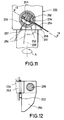
- the blade 254 is rotatable between a pair of stop surfaces 256 and 257 formed in the shaft 222 ( Figure 11).
- a torsional spring 258 is affixed between the opposite end of the shaft 253 and the driving shaft 222 ( Figure 9) for normally urging the blade 254 into engagement with the stop surface 256. This is the position when operating at idle or at low speed.
- the shaft 253 is provided with a cam surface defined by a flat section 259 which cooperates with the stop plunger 242 for varying its position.
- the position is as shown in solid lines in Figure 13 and the stop plunger 242 is at its extreme right hand position so as to limit the stroke of the pumping plunger 235 to its minimum value.
- the viscous resistance caused against the blade 254 ill cause it to pivot in a clockwise direction as shown in Figure 12 and cause the blade 254 to move away from the stop surface 256 toward the stop surface 257.
- stop device 252 temperature responsive. This can be done by making the blade 254 of a bi-metallic or memory responsive material, as shown at 261 in Figure 11. At a low temperature, the bi-metal blade 261 will achieve a curved configuration and less lubricant will be pumped than at normal temperatures. Of course, variations in the amount of delivery and temperature responsiveness of the device can be changed as desired to suit particular engine conditions.
- the pump is indicated generally by the reference numeral 301.
- the inlet passage 215 communicates directly with the supply chamber 264 and the passageway 245 is eliminated so that the chamber 214 does not communicate with the delivery passage 246. Therefore, the chamber 214 may be filled with a fluid 302 having a different viscosity than the lubricant pump.
- the bore 233 is appropriately sealed to the stop plunger 242 so as to preclude any leakage of fluid back into the lubricant being pumped.
- a breather tube 303 may be provided that is closed by a plug for filling the chamber 214 with the fluid 302.
- the vent tube 216 is provided to communicate with the area at the end of the sleeve 232 where the cam mechanism 236 is positioned. This will provide air venting from the lubricant as in the previously described embodiment.
- the equivalent of further viscosity increases can be achieved by placing either a large sphere in the chambers 214 of either embodiment or a plurality of smaller spheres. These will mix with the lubricant and provide a further way of tailoring the delivery curve to changes in speed.
- FIG. 15 Another embodiment of the present invention is shown in Figure 15 which, substantially, corresponds to the embodiment of Figure 14.
- the only difference relates to the provision of another means for increasing the viscuous resistance caused against the blade 254 in case said resistance is considered to be insufficient despite the measures explained in conjunction with the preceding embodiments.
- either a plurality of small steel balls may be mixed in the lubricating oil 302 in the oil chamber 214 or, as shown in Figure 15, one big steel ball 260 may be provided and introduced into the oil chamber 214 to modify the embodiments as shown in preceding Figures 9 and 14.
- Alternatively, also a plurality of such steel balls which are equal in size as said steel ball 260 can be provided in the oil chamber 214 of said pump arrangement.
Landscapes
- Engineering & Computer Science (AREA)
- General Engineering & Computer Science (AREA)
- Mechanical Engineering (AREA)
- Lubrication Of Internal Combustion Engines (AREA)
Description
- The present invention relates to a lubricant pump for an internal combustion engine as claimed in the preamble portion of
claim 1. - For appropriately lubricating internal combustion engines, one of the essentials comprises the supply of lubricating oil automatically with a rate appropriate to the current engine operating conditions.
- One form of lubricating system employed within internal combustion engines and particularly two cycle engines employs a reciprocating plunger type pump that is driven by the engine and supplies a finite amount of lubricant during each stroke of the pump. Of course, it is desirable to vary the output of the pump or the amount of lubricant delivered to the engine during each pump stroke so as to insure against excess lubrication and the disadvantages accompanying it. That is, it is desirable to insure against the supply of excess lubricant so as to avoid exhaust smoke and the emission of unburned hydrocarbons. A number of arrangements have been employed for controlling the amount of lubricant delivered to the engine during each pumping stroke.
- One way in which the amount of lubricant may be controlled is by changing the effective stroke of the plunger. This has conventionally been done in the past by providing some form of adjustable stop that cooperates with a portion of the plunger which is always exposed from the bore in which the plunger reciprocates. There are a number of disadvantages to such an arrangement.
- One disadvantage with this type of arrangement is that the clearance volume of the pump at top dead center of the plunger will then vary as the amount of lubricant pump is changed. That is, as the plunger stroke is adjusted, the clearance volume increases as the amount of lubricant is decreased. Having large clearance volumes presents a number of disadvantages. The primary disadvantage is that the larger the clearance volume, the more likely it is for air to be drawn into the pumping chamber during operation. This will give rise to variations in the amount of lubricant actually delivered and a decrease in the effectiveness of the pump.
- In addition, with this type of pumping mechanism, the plunger is supported in a blind bore. Therefore, it is necessary to provide some clearance at the end of the plunger stroke, even when the maximum amount of lubricant is being delivered. This must be done to insure against interference between the head of the plunger and the blind end of the bore. Thus, it is not possible under any condition to maintain minimum clearance volume with this type of pump stroke adjustment.
- The quantity of lubricant delivered to the engine is normally varied in response to an engine condition, most typically engine speed. The conventional types of systems, including those of the prior art as previously mentioned, adjust the stroke of the pump plunger in response to the setting of the speed controlling unit of the engine, such as the throttle valve. Normally this is done by providing a mechanical connection between the throttle valve or its controlling mechanism and the stop which changes the plunger stroke. As a result, these devices generally vary the amount of lubricant linearally with respect to engine speed.
- Devices have been incorporated, however, for changing this linearity somewhat in response to transient conditions, but the overall control is generally linear. However, the lubricant demands of the engine are not always linearally related to the engine condition.
- Another disadvantage of the type of lubricant control as afore-described is that the mechanical connection between the engine speed control and the lubricant pump also gives rise to mechanical loadings in the system which will change the operator's "feel" of the control of which he is attempting to effect. That is, if the pump output is adjusted in response to position of the throttle controlling member, then the feedback from the mechanical control to the pump adjustment will interfere with the operator's feel for the condition of the throttle valve. In addition, such arrangements add to the load which the operator must exert on the control in order to achieve the control of both the engine and the amount of lubricant supplied.
- Another disadvantge of the prior art type of systems wherein there is a mechanical connection between the pump output controlling member and the member that controls the engine condition is that the prior art devices generally can vary the amount of lubricant only with respect to that particular condition. For example, if the control is related to the engine throttle control, then the devices generally can vary the amount of lubricant only in response to throttle control position. However, the amount of lubricant required by the engine may vary in response to other condition than merely throttle position. Although the prior art mechanisms have permitted some minor adjustment, primarily for transient conditions, they have not been able to accommodate changes in lubrication for conditions in addition to the main sensed condition.
- In the past, lubricant pumps have already been proposed wherein the pump plunger in its maximal advanced position abuts against the adjusting plunger. For example, FR-A-1 400 280 shows a lubricant pump for a hydraulic press wherein the pump plunger actuated by hydraulic pressure contacts the adjusting plunger, thereby limiting the stroke of the pump plunger.
- A lubricant pump of the type described in the preamble of
claim 1 is known from GB-A-2 151 313. The lubricant pump proposed in this document employs a pair of check valves disposed in the delivery passage and the discharge passage, respectively. Aside from the fact that these check valves increase the flow resistance for the lubricant flowing through the respective passages, they cannot control the opening and the closing of the respective passages as exactly as desired. - Accordingly, it is an objective of this invention to provide a lubricant pump of the above-mentioned type which assures supply of lubricant with improved accuracy while allowing an easy manufacture of the pump.
- According to the present invention, this objective is performed by a lubricant pump described in
claim 1. - Preferred embodiments of the present invention are laid down in the further subclaims.
- In the following, the present invention is explained in greater detail by means of several embodiments thereof in conjunction with the accompanying drawings, wherein:
- Figure 1 is a partially schematic side elevational view of a motorcycle engine and control therefore, with a portion broken away and shown in section, and having a lubricating system and lubricating pump constructed in accordance with an embodiment of the invention,
- Figure 2 is an enlarged cross sectional view of the lubricant pump taken along a plane parallel to the plane of Figure 1.
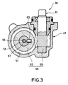
- Figure 3 is a cross sectional view taken along the line 3-3 of Figure 2.
- Figure 4 is a cross sectional view taken along the line 4-4 of Figure 2.
- Figure 5 is a cross sectional view taken along the line 5-5 of Figure 2.
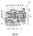
- Figure 6 is a partial cross sectional view taken generally along the line 6-6 of Figure 2.
- Figure 7 is a cross sectional view, in part similar to Figure 2, and shows another phase of the pump operation.
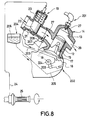
- Figure 8 is a partially schematic side elevational view, with a portion broken away, in part similar to Figure 1 and shows another embodiment of the invention.
- Figure 9 is a cross sectional view taken through the lubricant pump of this embodiment.
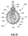
- Figure 10 is a cross sectional view taken along the line 11-11 of Figure 9.
- Figure 11 is a partial cross sectional view taken along the line 12-12 of Figure 9.
- Figure 13 is a cross sectional view taken along the line 13-13 of Figure 11.
- Figure 13 is a partial cross sectional view taken along a plane perpendicular to the plane of Figure 9 and shows how the pump stroke is adjusted in this embodiment and is taken generally along the line 14-14 of Figure 9.
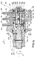
- Figure 14 is a cross sectional view, in part similar to Figure 9, and shows another embodiment of the invention.
- Figure 15 is similar to Figure 14, and shows another embodiment of the invention.
- Referring first to Figure 1, a motorcycle engine having a lubricating system constructed in accordance with an embodiment of the invention as shown partially and has portions broken away and identified generally by the
reference numeral 11. The invention is described in conjunction with a motorcycle application because motorcycles frequently employ two cycle internal combustion engines and this invention has particular utility in conjunction with such engines. It is to be understood, however, that the invention may be employed in lubricating systems for other types of engines or, for the matter, in lubricating systems for other types of machines. - The
engine 11 includes acylinder block 12 having acylinder bore 13 which is closed at one end by acylinder head 14 and in which apiston 15 reciprocates. Thepiston 15 drives acrankshaft 16 rotatably journaled within acrankcase chamber 17 formed by the lower portion of thecylinder block 12 and acrankcase member 18 that is affixed in a suitable manner to the cylinder block. - As has been noted, the
engine 11 operates on the two cycle principal and is of the crankcase compression type. A charge is delivered to thecrankcase chamber 17 from an induction system that includes acarburetor 19. Thecarburetor 19 has anintake passage 21 in which asliding throttle piston 22 is provided. Thethrottle piston 22 is normally biased towards its idle position by means of acoil compression spring 23. Athrottle control cable 24 is connected to a handgrip throttle control 25 by means including aconnector 26. - Air is drawn into the
carburetor intake passage 21 through an air cleaner and air silencer (not shown) and flows in the direction of the arrows to anintake passage 27 formed in thecylinder block 12 and which communicates with thecrankcase chamber 17 during the reciprocation of thepiston 15, as is well known in this art. - The charge which is drawn into the
crankcase chamber 17 during the upward movement of thepiston 15 is compressed as thepiston 15 descends in the cylinder bore 13. This compressed charge is then transferred to the combustion chamber formed above the end of thepiston 15 through one or more scavenge passages (not shown) in a manner well known in this art. This charge is then further compressed in the combustion chamber as thepiston 15 moves upwardly and is fired by means of aspark plug 27 mounted in thecylinder head 14. Thespark plug 27 is fired by an ignition system, indicated generally by theblock 28 and which may be of any known type. - An
exhaust passage 29 is formed in thecylinder block 12 and has positioned within it anexhaust control valve 31 which is operated by means of aservo motor 32 so as to change the timing of the opening and closing of theexhaust passage 29. Theexhaust control valve 31 is employed for retarding the opening of theexhaust port 29 under low and mid-range speeds as shown in the phantom line view of Figure 1 and to provide advanced opening of theexhaust passage 29 under high speed operation. ACPU 33 is provided for controlling both theservo motor 32 and the firing of thespark plug 27 by theignition system 28. - A engine speed and crank angle sensor, indicated by the
phantom line 34 inputs a signal to theignition system 28 and theCPU 33 so as to provide a speed and crank angle position for these members. Any other inputs may be supplied to theCPU 33 for its operation such as throttle position sensors, etc. - The foregoing description of the
engine 11 is only for reference purposes because, as has been noted, the invention may be employed in conjunction with various types of machines including two cycle crankcase compression internal combustion engines. Therefore, any details of the-construction as thus far described may be considered to be conventional and, for that reason, further discussion of the basic engine construction is not believed to be necessary to understand the construction and operation of the invention. - The invention deals primarily with the lubricating system for the engine which lubricating system is indicated generally by the
reference numeral 35 and specifically to the lubricating pump therefore, indicated generally by thereference numeral 36. Lubricant is supplied to thelubricating pump 36 from aremote lubricant reservoir 37 in which a quantity oflubricant 38 is contained. Thelubricant reservoir 37 is positioned vertically above thelubricant pump 36 and supplies lubricant thereto by gravity through aline 39. Thelubricant pump 36 has a discharge fitting 41 that delivers lubricant to theengine 11 for its lubrication through a lubricant supply conduit, indicated generally by thereference numeral 42. In the illustrated embodiment, theengine 11 is lubricated by spraying lubricant from thepump 36 into theintake port 27. It is to be understood, however, that the lubricant may be supplied to theengine 11 at one or more locations, as is well known in the art. - The amount of lubricant delivered by the
lubricant pump 36 is changed in response to engine operating conditions and a lubricantquantity controlling pulley 43 is associated with thelubricant pump 36 in a manner to be described so as to vary the stroke of thepump 36 and, accordingly, the amount of lubricant delivered. Thepulley 43 is operated by means of aBowden wire cable 44 that is connected to theconnector 26. In addition, awire transmitter 45 is also connected to amember 46 of theconnector 26 so that the amount of lubricant supplied will be generally responsive to the position of thethrottle control 25 but during transient conditions there will be some delay before the amount of lubricant supplied is changed. Theconnector 26 is of the type shown in Japanese published application 62-178707 published August 5, 1987. Of course, other types of controls for varying the position of thepulley 43 may be incorporated. - The
lubricant pump 36 will now be described in greater detail by reference to Figures 2 through 7. Thepump assembly 36 is comprised of amain housing piece 47 which is formed from a light weight material such as aluminum or aluminum alloy. Thehousing piece 46 is provided with aflange 48 so that it can be attached to thecrankcase 18 of the engine in driving relationship with thecrankshaft 16, in a manner which will be described. - The
main housing piece 47 is provided with an internal cavity that is defined by acylindrical bore 49 and alower cavity portion 51. Thelower cavity portion 51 is closed by means of acover plate 52 that is affixed to themain housing 47 by means of a plurality of threadedfasteners 53. The upper end of thebore 49 is covered by means of asecond closure plate 54 which is affixed to themain body portion 47 in a suitable manner as by fasteners 50 (Figure 5) and which defines an internal cavity in which the pump stroke adjusting mechanism, indicated generally by thereference numeral 55, is provided. - A
sleeve 56 having a throughbore 57 is rotatably journaled in the main housing bore 49. Thesleeve 56 may also be formed from a light weight material such as aluminum or an aluminum alloy. Thesleeve 56 is rotatably driven in thebore 49 by means of a worm gear assemblage, indicated generally by thereference numeral 58 and which includes aworm 59 that is formed integrally with ashaft 61 that has a suitable driving connection with thecrankshaft 16. - The
worm 59 drives aworm wheel 62, formed from a resinous plastic material has a driving connection with thesleeve 56 which is provided for by means of apin 63. Theworm wheel 62 is engaged at its upper end with ashoulder 64 formed by themain housing 47 and is engaged at its lower ends byupstanding bosses 65 of thecover piece 52. In this way, theworm wheel 62 andsleeve 56 are axially positioned within themain housing assembly 47. - As has been noted, the
sleeve 56 has a through bore and the axis of this bore is indicated by theline 66. Thisaxis 66 is coaxial with the axis of thebore 49 and apump plunger 67 is slidably supported in the lower end of this bore. Thepump plunger 67 has affixed to its lower end a cross pin 68 that is received in agap 69 formed by theupstanding bosses 65 of thecover piece 52. As a result, thepump plunger 67 will be held against rotations by thebosses 65 but may reciprocated within the bore of thesleeve 56. - Reciprocation of the
pump plunger 67 is effective by means of a pair of drivingcams 71 formed on the lower surface of theworm wheel 62. These cam surfaces 71 have a generally truncated configuration so that as theworm wheel 62 rotates, thepump plunger 67 will complete two strokes per revolution. - A
coil compression spring 72 is provided in thecover plate 52 and acts against the drive pin 68 so as to normally urge the drive pin 68 upwardly into engagement with thedrive cams 71 and also to urge thepump plunger 67 to an upward position. The direction of rotation of theworm wheel 62 is indicated by the arrow "A" in Figure 2. - As should be obvious, the downward stroke of the pumping
plunger 67 is controlled by the height of the drivingcams 71. This will determine the bottom dead center position of the pumpingplunger 67. The upward movement of the pumpingplunger 57 is, however, controlled by thespring 72 and by thestroke adjusting mechanism 55. Thisstroke adjusting mechanism 55 will now be described in detail by reference primarily to Figures 2, 5 and 6. - The
stroke limiting mechanism 55 includes an adjustingplunger 73 that is slidably supported in the bore of thesleeve 56 opposite to the pumpingplunger 67. The adjustingplunger 73 is urged by a mousetrap type spring 74 into engagement with astroke adjusting cam 75 having a generally snail like configuration. The adjustingcam 75 is connected for rotation with acamshaft 76 that includes ashaft element 77 by means of adrive pin 78. Thedrive pin 78 is restrained within a bore formed in the adjustingcam 75 and a corresponding bore in theshaft 77 by means of anO ring 79. It should be noted, and as clearly shown in Figure 6, that this driving connection permits the adjustingcam 75 to be shifted transversely relative to thecamshaft 77 for adjusting purposes, as will be described. - The
camshaft 77 is drivingly coupled to thepulley 43 by means of adrive pin 81. Atorsional spring 82 is loaded between thepulley 43 and thecover plate 54 for normally urging thecamshaft 77 andstroke adjusting cam 75 in a direction to force the adjustingplunger 73 to a downward, stroke limiting position. Direction is indicated by the arrow "B" in Figures 2 and 6. - The extreme lower position of the adjusting
plunger 73 when thecam 75 is rotated to its maximum limiting position is controlled by means of an adjusting mechanism, indicated generally by thereference numeral 83. Thisadjusting mechanism 83 includes afurther shaft 84 which is journaled within abore 85 of thecover piece 54 which bore 85 is co-axial with the axis of rotation of theshaft 77. The adjustingshaft 84 has aninternal bore 86 which is also co-axial with this shaft and in which a pilot portion of thecamshaft 77 is received. The adjustingshaft 84, however, has aneccentric portion 87 that is received within abore 88 of thecam 75. Thus, by rotating the adjustingshaft 84 relative to thecover plate 54 it is possible to adjust the minimum stroke of the pumpingplunger 67 so as to adjust the amount of lubricant delivered under idle conditions. - The adjusting
shaft 84 is locked in its adjusted position by means of a clampingplate 89 and lockscrew 91 fixed in thecover plate 54. - Fluid flow through the
pump 36 will now be described by particular reference to Figures 2 and 4. As has been noted, theconduit 39 supplies lubricant to thepump 36 from thereservoir 37. To this end, thelower cover plate 52 is provided with aninlet opening 92 by which fluid may flow into thechamber 51. A pair of vertically extendingdelivery passages sleeve 56.Radially extending ports housing 47 and extend to thebore 49. Thesleeve 56 is provided with adistributor passage 97 which will sequentially register with thesupply ports sleeve 56 rotates. This registration is accomplished at the time when the pumpingplunger 67 is moving downwardly under the operation of thedrive cam 71 so that fluid will be drawn into the pumpingchamber 57 upon this downward movement of the pumpingplunger 67. This direction of flow is indicated by the arrows "C" in Figure 4. - It may be seen that the
supply passages housing assembly 47 when thesleeve 56 is not in place with this drilled passageway intersecting thesupply passages ball type plug 98 is then inserted into this drilling to close the passages. - A pair of
delivery passages housing member 47 by a similar drilling that extends at ninety degrees (90°) to the drilling which forms thesupply passages ball type plug 102. - The
supply passages fittings type check valves delivery passages fittings passages distributor passage 97 of thesleeve 56 upon its rotation as shown by the arrows "D" in Figure 4. - The
fittings - The cover plate 52 (Figure 2) is provided with a
drain opening 107 which is normally closed bydrain plug 108. By removing thedrain plug 108 lubricant may be drained from thepump assembly 36. In addition thecover plate 54 is provided with avent opening 109 which is normally closed by avent plug 111. Air may be bled from thepump assembly 36 by loosening theplug 111 until lubricant flows out of thevent opening 109 and then theplug 111 may be re-tightened. If thepump 36 is operated in an inverted condition, the function of thedrain 108 and vent plugs 111 will obviously be reversed. - It should be noted that because the
plungers sleeve 56 andmain housing member 47 are all formed from the same material, there will be no problems of different thermal expansions and the pump can be operate quite smoothly and efficiently. Also, since thesleeve 56 is constantly rotating relative to the adjustingplunger 73, the frictional resistance to adjusting movement of the adjustingplunger 73 will be reduced and the components may be quite light in weight. Also, it is possible to use anon-metallic worm wheel 62 because of the light loading and this permits all elements to be generally light weight in construction. Furthermore, since theclearance volume 77 may be substantially zero at top dead center regardless of the amount of lubricant being pumped, the device is very effective in insuring against air intrusion into the system and excellent lubricant control may be achieved. - In the embodiment of the invention as thus far described, the pumping plunger of the
lubricant pump 36 has been mechanically driven. The invention may also be employed with pumps of the type wherein the pumping plunger is electrically driven. - In the embodiments of the invention as thus far described, the pump
stroke limiting plunger 73 has been connected by means of a Bowden wire cable to theconnector 46 of the throttle control mechanism. As has been previously noted, there are certain disadvantages with such an arrangement. The first of these disadvantages is that the supply of lubricant varies in a generally linear fashion with respect to the position of thethrottle pistons 22 and thehand throttle grip 25. As has been noted; theconnector 26 permits some adjustment in the lubricant output during transient conditions but the general control is linear. Of course, the slope of the curve can be changed but once the slope is determined, the relationship between lubricant supply and throttle valve position is in the same ratio. This is not always desirable. - In addition, the connection from the
stop plunger 73 back to thethrottle control 25 gives a feedback to the operator which will interfere with the throttle feel of the control system. Furthermore, this type of mechanism does not permit adjustment in the amount of lubricant supplied in response to other conditions, such as ambient temperature. - Figures 8 through 13 show another embodiment of the invention wherein the disadvantages as aforenoted are avoided and yet all of the advantages of the previously described embodiments are enjoyed.
- Referring initially to Figure 8, an engine constructed in accordance with this embodiment is identified generally by the
reference numeral 201. The basic construction of theengine 201 is the same as theengine 11 in Figure 1 and, for that reason, components of this embodiment which are the same as the previously described embodiment have been identified by the same reference numerals and will not be described again. It should be noted that in this embodiment, theexhaust control valve 31 of the previous embodiment is not illustrated. It is to be understood, however, that such an exhaust control valve can be employed in conjunction with this embodiment. - The general lubricating system in this embodiment is identified generally by the
reference numeral 202 and includes alubricating pump 203 which will be described in more detail by particular reference to Figures 9 through 13. Thislubricant pump 203 receives lubricant from alubricant reservoir 204 by gravity flow through asupply line 205. The lubricant in thereservoir 204 is indicated by thereference numeral 206. In addition to adelivery line 207 which sprays fuel into theintake passage 201 through acheck valve 208 there is provided avent line 209 which extends from thepump 203 back to thereservoir 204 above the level of thelubricant 206 therein. Thisvent line 209 will assist in venting air from thelubricant pump 203. It will be noted by the following discussion that this embodiment also, like the previously described embodiments, varies the liquid displacement of thepump 203 by a device which does not change the volume at top dead center and hence the intrusion of air into the system is minimized in the same manner as the previously described embodiments. - It should also be noted from Figure 8 that the
connector 26 of the embodiment of Figure 1 may be deleted and that there is no external connection from thelubricant pump 203 to any component of the engine other than its a driving connection. Hence, the feedback problems associated with thethrottle control 206 of the previous embodiments will not be present in this construction. - Referring now to Figures 9 through 13, the construction of the
pump 203 will be described in greater detail. Thepump 203 includes an outer housing indicated generally by thereference numeral 211 which has abore 212 that is closed at one end by aclosure plug 213 having a pilot portion that is received into thebore 212 with a press fit. Achamber 214 is formed at the end of thebore 212 opposite theclosure plug 213 and receives lubricant from thereservoir 204 through theline 205 and aninternal fitting 215 formed in thehousing member 211. A vent fitting 216 communicates thechamber 214 with thevent line 209 so that air which enters the system will be purged and returned back to thereservoir 204 through the vent line. - Adjacent the
chamber 214, themain housing 211 has apilot portion 217 that penetrates through anopening 218 formed in thecrankcase member 18 and which is sealed thereto by means of an O ring seal 219. Thispilot portion 217 is formed with abore 221 which rotatably journals a drivingshaft 222 which extends through thebore 221 and has affixed to it agear 223 that is enmeshed with agear 224 affixed to thecrankshaft 16 so as to establish a driving connection between thecrankshaft 16 and the drivingshaft 222 of thepump 203. - The
gear 223 is axially held on theshaft 222 by means of asnap ring 225 and is coupled for rotation with theshaft 222 by means of adrive pin 226. Thedriveshaft 222 is driven in the direction of the arrow "A" in Figure 10. Thedriveshaft 222 is provided with acircumferential groove 227 into which alocating pin 228 pressed into thehousing pilot portion 217 is received for axially locating the drivingshaft 222 while permitting its rotation about anaxis 229 which is coincident with the axis of thebore 221. - The driving
shaft 222 has a cylindrical portion that is received within abore 231 formed in asleeve member 232 that is positioned in the housing bore 212 adjacent theclosure plug 213. The portion of the drivingshaft 222 which is journaled within thesleeve member 232 is formed with abore 233 which extends through one of its ends and which terminates at across bore 234. 3ecause of this construction, thebore 233 may be considered to be a through bore as with the corresponding through bores of the previously described embodiments rather than a blind bore. Thus, the advantages of the previous constructions in this regard are also employed. - A pumping
plunger 235 is slidably supported within the outer end of thebore 233 and extends into a cavity formed between thesleeve 232 and theclosure member 213. This end of thesleeve 232 is formed with a drivingcam 236 which is engaged by adrive pin 237 that is affixed in a cross bore of the pumpingplunger 235. Acoil compression spring 239 urges thedrive pin 237 into engagement with thecam surface 236. - The
drive pin 237 and pumpingplunger 235 are, however, precluded from rotation by virtue of the fact that thedrive pin 237 is received within agroove 241 of acylindrical extension 238 if thesleeve 232. In this embodiment, thecam 236 and drivepin 237 is configured so as to provide only a single reciprocation per stroke rather than the two reciprocations per stroke as the embodiment of Figures 1 through 7. It is to be understood, however, that either pump may be employed with one, two or even more reciprocations per stroke, depending upon the total amount of lubricant desired to be pumped and the number of locations lubricated. - A
stop plunger 242 is also slidably positioned in thebore 233 and has a reduceddiameter portion 243 that is adapted to engage thepumping plunger 235 so as to limit its stroke, in a manner which will be described. A lightcoil compression spring 244 is received around the reduceddiameter portion 243 and urges thestop plunger 242 into engagement with its driving mechanism, to be described later. Thespring 244 is substantially lighter than thespring 239 so that its action on thepumping plunger 235 will not effect movement of the pumpingplunger 235 but merely reduces the effect of thespring 239 on thepumping plunger 235. - Fluid is delivered from the
chamber 214 to the area between the pumpingplunger 235 and thestop plunger 242 by means of a first drilledpassage 245 formed in thesleeve 232 which passes through asupplv chamber 246 formed intermediately in thesleeve 232 and also communicates thischamber 246 with the chamber in which thecam 236,drive pin 237 and pumpingplunger 235 are contained so as to lubricate these components. In addition, a second drilled passageway 247 (Figure 10) directly communicates thechamber 214 with the chamber formed at the end of thesleeve 232 by thecover plate 213. - A
distributor passage 248 is formed in thedriveshaft 222 and selectively communicates the pumping chamber formed between the pumpingplunger 235 and thestop plunger 242 with the supply chamber 246 (see Figure 10). This registry occurs when the pumpingplunger 235 is undergoing its suction stroke. Thedistributor passage 242 registers with an outlet fitting 249 having aflow passage 251 when theplunger 235 is undergoing its pumping stroke so as to deliver lubricant to the engine through theline 207. - The mechanism for operating the
stop plunger 242 for limiting the stroke of the pumpingplunger 235 will now be described in detail by particular reference to Figures 9 and 11 through 13. The stop actuating mechanism is indicated generally by thereference numeral 252 and includes ashaft 253 that is rotatably journaled in thetransverse bore 234 of thedriveshaft 222 previously referred to. One end of theshaft 253 extends it thechamber 214 and has affixed to it ablade 254 by means of ascrew 255. Theblade 254 is rotatable between a pair of stop surfaces 256 and 257 formed in the shaft 222 (Figure 11). Atorsional spring 258 is affixed between the opposite end of theshaft 253 and the driving shaft 222 (Figure 9) for normally urging theblade 254 into engagement with thestop surface 256. This is the position when operating at idle or at low speed. - As may be seen in Figure 13, the
shaft 253 is provided with a cam surface defined by aflat section 259 which cooperates with thestop plunger 242 for varying its position. When thespring 258 urges theblade 254 into engagement with thestop 256, the position is as shown in solid lines in Figure 13 and thestop plunger 242 is at its extreme right hand position so as to limit the stroke of the pumpingplunger 235 to its minimum value. However, as the speed of rotation of the drivingshaft 222 increases, the viscous resistance caused against theblade 254 ill cause it to pivot in a clockwise direction as shown in Figure 12 and cause theblade 254 to move away from thestop surface 256 toward thestop surface 257. When this movement occurs, the flat 259 will be brought into registry with the end of thestop plunger 242 and thespring 243 will urge thestop plunger 242 in a direction to increase the stroke of the pumpingplunger 235. The angular position will depend on the speed of rotation ofshaft 222 and will continue until theblade 254 engages thestop surface 257 at a high speed of the engine. By changing the surface area of theblade 254 and the distance between thestops - In addition to these features, it is also possible to make the
stop device 252 temperature responsive. This can be done by making theblade 254 of a bi-metallic or memory responsive material, as shown at 261 in Figure 11. At a low temperature, thebi-metal blade 261 will achieve a curved configuration and less lubricant will be pumped than at normal temperatures. Of course, variations in the amount of delivery and temperature responsiveness of the device can be changed as desired to suit particular engine conditions. - In the embodiment of Figures 8 through 13, the viscous liquid operating on the
stop controlling mechanism 252 was the same as the lubricant being pumped. In order to provide further tailoring of the delivery curve, a separate fluid having a different viscosity may be employed and Figure 14 shows how such an embodiment can be constructed. This embodiment is generally the same as the previously described embodiment and, for that reason, components which are the same as those previously described have been identified by the same reference numerals and will not be described again, except insofar as is necessary to understand the construction and operation of this embodiment. - In this embodiment, the pump is indicated generally by the
reference numeral 301. Unlike the previously described embodiment, however, theinlet passage 215 communicates directly with thesupply chamber 264 and thepassageway 245 is eliminated so that thechamber 214 does not communicate with thedelivery passage 246. Therefore, thechamber 214 may be filled with a fluid 302 having a different viscosity than the lubricant pump. Thebore 233 is appropriately sealed to thestop plunger 242 so as to preclude any leakage of fluid back into the lubricant being pumped. In this event, abreather tube 303 may be provided that is closed by a plug for filling thechamber 214 with thefluid 302. As a result of this, thevent tube 216 is provided to communicate with the area at the end of thesleeve 232 where thecam mechanism 236 is positioned. This will provide air venting from the lubricant as in the previously described embodiment. - In the event the desired delivery curve shape in relation to speed cannot be obtained by altering the viscosity of the fluid in the
chamber 214 in accordance with the embodiment of either Figures 8 through 13 or Figure 14 or by changing the size of theblade 254 or volume of this chamber, the equivalent of further viscosity increases can be achieved by placing either a large sphere in thechambers 214 of either embodiment or a plurality of smaller spheres. These will mix with the lubricant and provide a further way of tailoring the delivery curve to changes in speed. - Another embodiment of the present invention is shown in Figure 15 which, substantially, corresponds to the embodiment of Figure 14. The only difference relates to the provision of another means for increasing the viscuous resistance caused against the
blade 254 in case said resistance is considered to be insufficient despite the measures explained in conjunction with the preceding embodiments. In that case, either a plurality of small steel balls may be mixed in thelubricating oil 302 in theoil chamber 214 or, as shown in Figure 15, onebig steel ball 260 may be provided and introduced into theoil chamber 214 to modify the embodiments as shown in preceding Figures 9 and 14. Alternatively, also a plurality of such steel balls which are equal in size as saidsteel ball 260 can be provided in theoil chamber 214 of said pump arrangement. - It should be readily apparent from the foregoing description that the described embodiments of the invention are extremely effective in providing effective control of the stroke of the pumping plunger while always maintaining substantially zero clearance volume at top dead center regardless of the amount of lubricant being pumped. Accordingly, air intrusion is substantially avoided and extremely effective control of the amount of lubricant pump is possible. In addition, in the embodiments of Figures 9 through 13 and Figure 14 it is possible to vary the amount of lubricant supplied in a non-linear fashion with respect to engine speed and also to provide temperature compensation in the amount of lubricant pumped without any direct mechanical connection to the engine speed control mechanisms. Of course, the foregoing description is that of preferred embodiments of the invention.
Claims (15)
- Lubricant pump (36, 203, 301) for an internal combustion engine comprising a pump plunger (67, 235) reciprocated within a bore defining a pump chamber (57) therein into which the lubricant is introduced through a delivery passage (93, 94, 245) during a suction stroke of the pump plunger (67, 235) and from which the lubricant is discharged during a compression stroke of the pump plunger (67, 235) through a discharge passage (99, 101, 248), means (71, 72, 236, 239) for reciprocating said pump plunger (67, 235) within said bore and an adjusting plunger (73, 242) for limiting the stroke of said pump plunger (67, 235), which, in its maximal advanced position, abuts against the adjusting plunger (73, 175, 242),
characterised in that
the pump plunger (67, 235) and the adjusting plunger (73, 242) are slidably received within a sleeve (56, 222) which is, in turn, rotatably received within a housing bore (49, 231), said sleeve (56, 222) being provided with a distributor passage (97, 248) which, depending on the rotatory position of the sleeve, communicates the pump chamber with said delivery passage (93, 94, 245) and said discharge passage (99, 101, 248), respectively. - Lubricant pump as claimed in claim 1, characterised in that, a pump stroke adjusting mechanism (55,252) is provided for adjusting the axial position of the adjusting plunger (73,242) in response to engine operating or environmental conditions.
- Lubricant pump as claimed in claims 1 or 2, characterised in that, the pump plunger driving means comprises a worm gear assemblage (58) for transmitting driving power of a crankshaft (16) through said rotatable sleeve (56) said worm gear assemblage (58) having a worm wheel (62) made of synthetic resin connected to the sleeve (56) to rotate same about its axis (66).
- Lubricant pump as claimed in claim 3, characterised in that, the worm wheel (62) has two opposite driving cams (71) adapted to engage a cross pin (68) disposed at an outer end of the driving pump plunger (67), said cross pin (68) being spring-biased to urge the pump plunger (67) in its advanced abutting position against the adjusting plunger (73), wherein guide grooves (69) are provided to slidably accommodate said cross pin (68) for slide movement together with the pump plunger (67).
- Lubricant pump as claimed in claim 4, characterised in that, the worm wheel (62) and the rotatable sleeve (56) are disposed rotatable relative to each other through a worm (59) which is integral with a shaft (61) that has a driving connection with the crankshaft (16), wherein the driving cams (71) on the worm wheel (62) for a pumping stroke of the pump plunger (67) temporarily engage the projected ends of the cross pin (68) urging the pump plunger (67) axially outwardly while, under further rotation of the worm wheel (62), when the projected ends of the cross pin (68) are positioned between the driving cams (71) so as to be disengaged therefrom, the driving pump plunger (67) is returned towards its advanced abutting position by a prebiasing compression spring (72) performing a pump stroke.
- Lubricant pump as claimed in at least one of the preceding claims 1 to 5, characterised in that, a main housing piece (47) comprises a lubricant introducing structure (92) to fill the main housing piece (47) entirely with lubricating oil while a pair of delivery passages (93, 94) extend partially around the sleeve (56), connected to radially extending supply ports (95,96) disposed opposite to each other with respect to the sleeve (56), and a pair of discharge passages (99,101) disposed substantially at a mid-portion between the supplying ports (95,96) and provided with check valves (105,106) respectively, said sleeve (56) comprises a distributor passage (97) to be sequentially in register with the supply ports (95,96) and the discharge passages (99,101) of the main housing piece (47).
- Lubricant pump as claimed in at least one of the preceding claims 2 to 6, characterised in that, the pump stroke adjusting mechanism (55) comprises a cam shaft (77), the axis of which is disposed perpendicularly to the axis of the adjusting plunger (73) above same, said camshaft (77) is rotatably supported through an upper cover member (54) of the pump and is driven by a drive pulley (43) whereas a stroke adjusting cam (75) is adjustably supported by means of an eccentric adjusting shaft (84) which supports a free end of the camshaft (77).
- Lubricant pump as claimed in at least one of the preceding claims 1 to 7, characterised in that, the axial position of the adjusting plunger (73) is controlled in response to a condition of an engine throttle control means.
- Lubricant pump as claimed in claim 1, characterised in that, the axial position of the stop member (242) is controlled non-linearly in response to an engine operating condition and/or temperature of the lubricant or a temperature the pump is subject to.
- Lubricant pump as claimed in claim 9, characterised in that, the means for moving the stop member (242) is a viscous fluid.
- Lubricant pump as claimed in claims 9 or 10, characterised in that, the stop member is an adjusting plunger (242) and the means for determining an axial position of the adjusting plunger (242) comprises a rotating blade (254) disposed within the viscous fluid, said prebiased blade (254) is made to change its angular position in response to its speed of rotation within the viscous fluid, the viscosity of same and the surface area of the blade (254).
- Lubricant pump as claimed in claims 10 and 11, characterised in that, said viscous control fluid comprises the lubricant being pumped.
- Lubricant pump as claimed in claims 11 and 12, characterised in that, said blade (254) being rotatable between a pair of stop member (256,257), the position of which is variable to vary the pump stroke of the pump plunger (235).
- Lubricant pump as claimed in claim 13, characterised in that, the position of the stop members (256,257) being temperature-responsive.
- Lubricant pump as claimed in claim 13, characterised in that, the material of the blade (254) is temperature-responsive to change the shape of the blade (254) in response to a change of the surrounding temperature.
Applications Claiming Priority (2)
| Application Number | Priority Date | Filing Date | Title |
|---|---|---|---|
| JP201297/91 | 1991-07-15 | ||
| JP20129791 | 1991-07-15 |
Publications (2)
| Publication Number | Publication Date |
|---|---|
| EP0523646A1 EP0523646A1 (en) | 1993-01-20 |
| EP0523646B1 true EP0523646B1 (en) | 1996-10-16 |
Family
ID=16438657
Family Applications (1)
| Application Number | Title | Priority Date | Filing Date |
|---|---|---|---|
| EP92112052A Expired - Lifetime EP0523646B1 (en) | 1991-07-15 | 1992-07-15 | Lubricant pump for an internal combustion engine |
Country Status (3)
| Country | Link |
|---|---|
| US (1) | US5315971A (en) |
| EP (1) | EP0523646B1 (en) |
| DE (1) | DE69214542T2 (en) |
Families Citing this family (16)
| Publication number | Priority date | Publication date | Assignee | Title |
|---|---|---|---|---|
| US5377637A (en) * | 1991-06-21 | 1995-01-03 | Orbital Engine Company (Australia) Pty. Limited | Method and apparatus for metering oil for a two stroke cycle internal combustion engine |
| EP0753102A4 (en) * | 1994-03-29 | 1998-12-23 | Orbital Eng Pty | Pump control system |
| JPH0814093A (en) * | 1994-06-24 | 1996-01-16 | Sanshin Ind Co Ltd | Starting control device for two-cycle engine |
| DE19529368C1 (en) * | 1995-08-10 | 1996-10-31 | Dolmar Gmbh | Fuel injection and lubricant feed system for combustion engine |
| US5829395A (en) * | 1996-05-08 | 1998-11-03 | Racine Railroad Products, Inc. | Rail saw power head with two cycle engine and lube oil metering system |
| US5806499A (en) | 1997-03-18 | 1998-09-15 | Cummins Engine Company, Inc. | Dedicated overhead cam shaft for unit injector |
| US5884601A (en) * | 1998-02-02 | 1999-03-23 | Siemens Canada Limited | Electric motor driven primary oil pump for an internal combustion engine |
| DE19808887A1 (en) * | 1998-03-03 | 1999-09-09 | Dolmar Gmbh | Hand tool with 2-stroke internal combustion engine and separate lubrication as well as a combined feed / metering pump for such a hand tool |
| JPH11324631A (en) * | 1998-05-14 | 1999-11-26 | Kioritz Corp | Separation lubrication system for internal combustion engines |
| US6269788B1 (en) * | 2000-03-13 | 2001-08-07 | Robert L. Kachelek | Programmable computer controlled electric oil pump drive for engines |
| US7674095B2 (en) * | 2000-12-12 | 2010-03-09 | Borgwarner Inc. | Variable displacement vane pump with variable target regulator |
| US6790013B2 (en) | 2000-12-12 | 2004-09-14 | Borgwarner Inc. | Variable displacement vane pump with variable target regulator |
| DE10161131B4 (en) * | 2000-12-12 | 2013-11-07 | Slw Automotive Inc. | Vane pump variable displacement |
| US7726948B2 (en) * | 2002-04-03 | 2010-06-01 | Slw Automotive Inc. | Hydraulic pump with variable flow and variable pressure and electric control |
| EP1350930B2 (en) * | 2002-04-03 | 2016-01-27 | SLW Automotive Inc. | Variable displacement pump and control therefor |
| JP3880982B2 (en) * | 2004-07-01 | 2007-02-14 | 株式会社共立 | Oil pump device for lubricating the saw chain |
Family Cites Families (13)
| Publication number | Priority date | Publication date | Assignee | Title |
|---|---|---|---|---|
| US2253152A (en) * | 1937-08-16 | 1941-08-19 | Towler Frank Hathorn | High speed reciprocating ram pump |
| FR1400280A (en) * | 1964-07-07 | 1965-05-21 | Zd Y V I Plzen Narodni Podnik | Method and installation for the automatic lubrication of hydraulic presses |
| US3302752A (en) * | 1964-10-21 | 1967-02-07 | Yamaha Motor Co Ltd | Lubricating pump for two-cycle gasoline internal combustion engine |
| US3938425A (en) * | 1974-04-15 | 1976-02-17 | Houdaille Industries, Inc. | Pump stroke adjustment device |
| US4539949A (en) * | 1981-10-08 | 1985-09-10 | Outboard Marine Corporation | Combined fluid pressure actuated fuel and oil pump |
| US4383504A (en) * | 1981-11-23 | 1983-05-17 | Outboard Marine Corporation | Marine propulsion device with mechanical fuel pressure operated device for supplying a fuel/oil mixture |
| GB2151312B (en) * | 1981-10-23 | 1986-04-23 | Outboard Marine Corporated | Fluid-pressure-actuated motor |
| US4533301A (en) * | 1983-04-13 | 1985-08-06 | Foster Leslie W | Pump |
| US4551076A (en) * | 1983-10-07 | 1985-11-05 | Outboard Marine Corporation | Fluid driven pump with one-way valve in fluid inlet |
| SE463221B (en) * | 1985-08-21 | 1990-10-22 | Tetra Pak Ab | Dosing pump |
| JPH0811931B2 (en) * | 1986-05-02 | 1996-02-07 | ヤマハ発動機株式会社 | Lubricating oil supply device for 2-cycle engine |
| DE3818802C2 (en) * | 1988-06-03 | 1994-05-26 | Baier & Koeppel | Lubricant pump with stroke actuation of a delivery piston and with an adjustable dosage |
| FR2641338A1 (en) * | 1988-12-30 | 1990-07-06 | Peugeot Motocycles | LOW FLOW PUMP, PARTICULARLY FOR LUBRICATING A TWO-STROKE ENGINE |
-
1992
- 1992-06-09 US US07/895,919 patent/US5315971A/en not_active Expired - Fee Related
- 1992-07-15 DE DE69214542T patent/DE69214542T2/en not_active Expired - Fee Related
- 1992-07-15 EP EP92112052A patent/EP0523646B1/en not_active Expired - Lifetime
Also Published As
| Publication number | Publication date |
|---|---|
| EP0523646A1 (en) | 1993-01-20 |
| US5315971A (en) | 1994-05-31 |
| DE69214542T2 (en) | 1997-02-20 |
| DE69214542D1 (en) | 1996-11-21 |
Similar Documents
| Publication | Publication Date | Title |
|---|---|---|
| US5315971A (en) | Lubricating oil supplying device for engine | |
| US4134549A (en) | Injectors of a fuel supply system for an internal combustion engine | |
| JPS6343396Y2 (en) | ||
| US6799953B2 (en) | Port plate for an axial piston pump | |
| US3302752A (en) | Lubricating pump for two-cycle gasoline internal combustion engine | |
| US4224916A (en) | Timing control for fuel injection pump | |
| US5806631A (en) | Piston pin lubrication | |
| US4329961A (en) | Diesel injection pump timing control with electronic adjustment | |
| EP0410405B1 (en) | Viscosity responsive flow controlling system | |
| EP0057077B1 (en) | Fuel injection pump | |
| EP0381162B1 (en) | Oil feeding method and device for oiling a 2-cycle engine | |
| US4100903A (en) | Rotary distributor fuel injection pump | |
| US4036195A (en) | Unit fuel injector | |
| JPH04301148A (en) | Device for adjusting oil pressure in control chamber of reciprocating pistion having compression height | |
| JPH0219300B2 (en) | ||
| US2816533A (en) | Fluid pump system | |
| US4354474A (en) | Fuel injection advance angle control apparatus | |
| US5353759A (en) | Crank chamber compression type two cycle engine | |
| US4121559A (en) | Lubricant oil pump for two-cycle engines | |
| US3435914A (en) | Oil pump for an engine | |
| US4787832A (en) | Automatic air vent device for fluid pump of internal combustion engine | |
| US3856438A (en) | Fuel injection pump | |
| US3707955A (en) | Engine apparatus | |
| US2754814A (en) | Lubrication means for internal combustion engines | |
| US3144095A (en) | Oiling system |
Legal Events
| Date | Code | Title | Description |
|---|---|---|---|
| PUAI | Public reference made under article 153(3) epc to a published international application that has entered the european phase |
Free format text: ORIGINAL CODE: 0009012 |
|
| AK | Designated contracting states |
Kind code of ref document: A1 Designated state(s): DE FR GB IT |
|
| 17P | Request for examination filed |
Effective date: 19930719 |
|
| 17Q | First examination report despatched |
Effective date: 19930924 |
|
| GRAH | Despatch of communication of intention to grant a patent |
Free format text: ORIGINAL CODE: EPIDOS IGRA |
|
| GRAH | Despatch of communication of intention to grant a patent |
Free format text: ORIGINAL CODE: EPIDOS IGRA |
|
| GRAA | (expected) grant |
Free format text: ORIGINAL CODE: 0009210 |
|
| AK | Designated contracting states |
Kind code of ref document: B1 Designated state(s): DE FR GB IT |
|
| REF | Corresponds to: |
Ref document number: 69214542 Country of ref document: DE Date of ref document: 19961121 |
|
| ITF | It: translation for a ep patent filed | ||
| ET | Fr: translation filed | ||
| PLBE | No opposition filed within time limit |
Free format text: ORIGINAL CODE: 0009261 |
|
| STAA | Information on the status of an ep patent application or granted ep patent |
Free format text: STATUS: NO OPPOSITION FILED WITHIN TIME LIMIT |
|
| 26N | No opposition filed | ||
| REG | Reference to a national code |
Ref country code: GB Ref legal event code: IF02 |
|
| PGFP | Annual fee paid to national office [announced via postgrant information from national office to epo] |
Ref country code: FR Payment date: 20020709 Year of fee payment: 11 |
|
| PGFP | Annual fee paid to national office [announced via postgrant information from national office to epo] |
Ref country code: GB Payment date: 20020710 Year of fee payment: 11 |
|
| PGFP | Annual fee paid to national office [announced via postgrant information from national office to epo] |
Ref country code: DE Payment date: 20020724 Year of fee payment: 11 |
|
| PG25 | Lapsed in a contracting state [announced via postgrant information from national office to epo] |
Ref country code: GB Free format text: LAPSE BECAUSE OF NON-PAYMENT OF DUE FEES Effective date: 20030715 |
|
| PG25 | Lapsed in a contracting state [announced via postgrant information from national office to epo] |
Ref country code: DE Free format text: LAPSE BECAUSE OF NON-PAYMENT OF DUE FEES Effective date: 20040203 |
|
| GBPC | Gb: european patent ceased through non-payment of renewal fee |
Effective date: 20030715 |
|
| PG25 | Lapsed in a contracting state [announced via postgrant information from national office to epo] |
Ref country code: FR Free format text: LAPSE BECAUSE OF NON-PAYMENT OF DUE FEES Effective date: 20040331 |
|
| REG | Reference to a national code |
Ref country code: FR Ref legal event code: ST |
|
| PG25 | Lapsed in a contracting state [announced via postgrant information from national office to epo] |
Ref country code: IT Free format text: LAPSE BECAUSE OF NON-PAYMENT OF DUE FEES;WARNING: LAPSES OF ITALIAN PATENTS WITH EFFECTIVE DATE BEFORE 2007 MAY HAVE OCCURRED AT ANY TIME BEFORE 2007. THE CORRECT EFFECTIVE DATE MAY BE DIFFERENT FROM THE ONE RECORDED. Effective date: 20050715 |