EP0522833A1 - Heat shield for a compressor stator structure - Google Patents
Heat shield for a compressor stator structure Download PDFInfo
- Publication number
- EP0522833A1 EP0522833A1 EP92306243A EP92306243A EP0522833A1 EP 0522833 A1 EP0522833 A1 EP 0522833A1 EP 92306243 A EP92306243 A EP 92306243A EP 92306243 A EP92306243 A EP 92306243A EP 0522833 A1 EP0522833 A1 EP 0522833A1
- Authority
- EP
- European Patent Office
- Prior art keywords
- casing
- cavity
- honeycomb cells
- gas turbine
- flow
- Prior art date
- Legal status (The legal status is an assumption and is not a legal conclusion. Google has not performed a legal analysis and makes no representation as to the accuracy of the status listed.)
- Withdrawn
Links
- 238000000034 method Methods 0.000 claims description 7
- 239000012212 insulator Substances 0.000 claims 1
- 239000007789 gas Substances 0.000 description 15
- 238000009413 insulation Methods 0.000 description 8
- 239000012530 fluid Substances 0.000 description 4
- 239000000463 material Substances 0.000 description 3
- 239000002184 metal Substances 0.000 description 3
- 230000003685 thermal hair damage Effects 0.000 description 3
- 241000270295 Serpentes Species 0.000 description 2
- 230000000694 effects Effects 0.000 description 2
- 239000002657 fibrous material Substances 0.000 description 2
- 238000010438 heat treatment Methods 0.000 description 2
- 230000013011 mating Effects 0.000 description 2
- 238000000926 separation method Methods 0.000 description 2
- 230000003068 static effect Effects 0.000 description 2
- 230000015572 biosynthetic process Effects 0.000 description 1
- 230000001627 detrimental effect Effects 0.000 description 1
- 239000003112 inhibitor Substances 0.000 description 1
- 238000009434 installation Methods 0.000 description 1
- 238000004519 manufacturing process Methods 0.000 description 1
- 238000012986 modification Methods 0.000 description 1
- 230000004048 modification Effects 0.000 description 1
- 230000003071 parasitic effect Effects 0.000 description 1
- 238000005086 pumping Methods 0.000 description 1
- 238000007789 sealing Methods 0.000 description 1
- 238000005382 thermal cycling Methods 0.000 description 1
Images


Classifications
-
- F—MECHANICAL ENGINEERING; LIGHTING; HEATING; WEAPONS; BLASTING
- F01—MACHINES OR ENGINES IN GENERAL; ENGINE PLANTS IN GENERAL; STEAM ENGINES
- F01D—NON-POSITIVE DISPLACEMENT MACHINES OR ENGINES, e.g. STEAM TURBINES
- F01D25/00—Component parts, details, or accessories, not provided for in, or of interest apart from, other groups
- F01D25/08—Cooling; Heating; Heat-insulation
- F01D25/14—Casings modified therefor
- F01D25/145—Thermally insulated casings
-
- Y—GENERAL TAGGING OF NEW TECHNOLOGICAL DEVELOPMENTS; GENERAL TAGGING OF CROSS-SECTIONAL TECHNOLOGIES SPANNING OVER SEVERAL SECTIONS OF THE IPC; TECHNICAL SUBJECTS COVERED BY FORMER USPC CROSS-REFERENCE ART COLLECTIONS [XRACs] AND DIGESTS
- Y10—TECHNICAL SUBJECTS COVERED BY FORMER USPC
- Y10T—TECHNICAL SUBJECTS COVERED BY FORMER US CLASSIFICATION
- Y10T29/00—Metal working
- Y10T29/49—Method of mechanical manufacture
- Y10T29/49229—Prime mover or fluid pump making
- Y10T29/49231—I.C. [internal combustion] engine making
-
- Y—GENERAL TAGGING OF NEW TECHNOLOGICAL DEVELOPMENTS; GENERAL TAGGING OF CROSS-SECTIONAL TECHNOLOGIES SPANNING OVER SEVERAL SECTIONS OF THE IPC; TECHNICAL SUBJECTS COVERED BY FORMER USPC CROSS-REFERENCE ART COLLECTIONS [XRACs] AND DIGESTS
- Y10—TECHNICAL SUBJECTS COVERED BY FORMER USPC
- Y10T—TECHNICAL SUBJECTS COVERED BY FORMER US CLASSIFICATION
- Y10T29/00—Metal working
- Y10T29/49—Method of mechanical manufacture
- Y10T29/49229—Prime mover or fluid pump making
- Y10T29/49297—Seal or packing making
-
- Y—GENERAL TAGGING OF NEW TECHNOLOGICAL DEVELOPMENTS; GENERAL TAGGING OF CROSS-SECTIONAL TECHNOLOGIES SPANNING OVER SEVERAL SECTIONS OF THE IPC; TECHNICAL SUBJECTS COVERED BY FORMER USPC CROSS-REFERENCE ART COLLECTIONS [XRACs] AND DIGESTS
- Y10—TECHNICAL SUBJECTS COVERED BY FORMER USPC
- Y10T—TECHNICAL SUBJECTS COVERED BY FORMER US CLASSIFICATION
- Y10T29/00—Metal working
- Y10T29/49—Method of mechanical manufacture
- Y10T29/49826—Assembling or joining
- Y10T29/49947—Assembling or joining by applying separate fastener
- Y10T29/49948—Multipart cooperating fastener [e.g., bolt and nut]
-
- Y—GENERAL TAGGING OF NEW TECHNOLOGICAL DEVELOPMENTS; GENERAL TAGGING OF CROSS-SECTIONAL TECHNOLOGIES SPANNING OVER SEVERAL SECTIONS OF THE IPC; TECHNICAL SUBJECTS COVERED BY FORMER USPC CROSS-REFERENCE ART COLLECTIONS [XRACs] AND DIGESTS
- Y10—TECHNICAL SUBJECTS COVERED BY FORMER USPC
- Y10T—TECHNICAL SUBJECTS COVERED BY FORMER US CLASSIFICATION
- Y10T29/00—Metal working
- Y10T29/49—Method of mechanical manufacture
- Y10T29/49826—Assembling or joining
- Y10T29/49947—Assembling or joining by applying separate fastener
- Y10T29/49963—Threaded fastener
-
- Y—GENERAL TAGGING OF NEW TECHNOLOGICAL DEVELOPMENTS; GENERAL TAGGING OF CROSS-SECTIONAL TECHNOLOGIES SPANNING OVER SEVERAL SECTIONS OF THE IPC; TECHNICAL SUBJECTS COVERED BY FORMER USPC CROSS-REFERENCE ART COLLECTIONS [XRACs] AND DIGESTS
- Y10—TECHNICAL SUBJECTS COVERED BY FORMER USPC
- Y10T—TECHNICAL SUBJECTS COVERED BY FORMER US CLASSIFICATION
- Y10T29/00—Metal working
- Y10T29/49—Method of mechanical manufacture
- Y10T29/49826—Assembling or joining
- Y10T29/49947—Assembling or joining by applying separate fastener
- Y10T29/49966—Assembling or joining by applying separate fastener with supplemental joining
- Y10T29/49968—Metal fusion joining
Definitions
- the present invention pertains to heat shields for gas turbine engines and, more particularly, to a heat shield mechanism having a plurality of honeycomb cells aligned in a radially outward manner and which are resiliently biased to maintain at least one honeycomb cell of the plurality of honeycomb cells in contact with an engine casing so as to reduce and eliminate flow gaps between the honeycomb cells and casing.
- thermal insulation blankets have been used to shield compressor casing walls from the flow path of hot gases that leak through the vane retainers after exiting the compressor stage of the engine. These hot gases are known to cause thermal damage to the casing and detrimentally affect engine performance.
- the invention provides a method of assembling a gas turbine engine, the gas turbine engine including a casing defining in part at least one cavity for separating the flow of high energy compressed air from the casing, a thermal shield including a plurality of adjacent honeycomb cells each having an open end and a closed end, the method comprising the steps of : associating the thermal shield in thermal insulating relation with the casing within the at least one cavity and arranging the thermal shield in engagement with the casing generally about at least some of the open ends of the honeycomb cells with the thermal shield adjacent the closed ends of the honeycomb cells being exposed to the at least one cavity during the associating step; and resiliently biasing the thermal shield into engagement with the casing to impede and slow down the flow of high energy compressed air.
- the invention provides a gas turbine engine comprising : a casing defining in part at least one cavity for separating the flow of compressed air within said engine from said casing; means for thermally insulating said casing within said at least one cavity, said thermally insulating means including a plurality of generally adjacent honeycomb cells each having an open end and a close end, said thermally insulating means being engaged with said casing generally about the open end of at least some of said honeycomb cells and being exposed to said at least one cavity adjacent said closed ends of said honeycomb cells; and means for resiliently biasing said thermally insulating means into engagement with said casing.
- features of the present invention are to provide a novel heat shield mechanism for thermally isolating a casing contained in a turbine engine from leaked hot flow path gases; to improve engine performance by achieving reduced blade-case radial clearance by reducing the casing temperature; and to improve the creep life of the casing flange thereby maintaining the original manufactured dimensions.
- a preferred embodiment provides a heat shield mechanism for thermally protecting a casing located in a turbine engine.
- the heat shield mechanism comprises a plurality of metal honeycomb cells connected to a support plate.
- the plurality of honeycomb cells is aligned in a radially outward manner.
- Resilient biasing means such as a spring acts as a gap reducing means and continuously urges the heat shield radially outward into engagement with an adjacent inner surface of the casing.
- the spring exerts a force on the honeycomb cells causing them to be in proximate contact with the casing of the turbine engine.
- FIG. 1 there is shown a partial cross-sectional drawing of an exemplary high-bypass ratio gas turbine engine 10 having a rotor engine portion indicated at 12 and a stator or fan portion indicated at 14.
- the engine portion 12 may be referred to as the rotor module.
- the rotor engine portion 12 includes an intermediate pressure compressor or booster stage 16, a high pressure compressor stage 18, a combustor stage 20, a high pressure turbine stage 21, and a low pressure turbine stage 22 all aligned on an engine centerline 23.
- the engine further includes fan blades 24 and a spinner assembly 28.
- the fan portion 14 comprises fan cowling 27 and fan casing 26.
- the fan cowling 27 surrounds the fan casing 26 and radially encloses the fan portion of the engine 10.
- the fan spinner assembly 28 located forward of the fan blades 24 connects to a rotor assembly (not shown) drivingly coupled to blades 24 and being driven by turbine stage 22.
- a rotor assembly (not shown) drivingly coupled to blades 24 and being driven by turbine stage 22.
- To the aft of fan blades 24 is located a plurality of circumferentially spaced outlet guide vanes or fan frame struts 30 which are a part of the fan portion 14.
- the outlet guide vanes 30 connect the engine portion 12 to the fan portion of the engine 10 and provide structural support.
- primary nozzle 33 which includes an outer member 34 and an inner member 35.
- the fan shaft 37 driven by turbine stage 22 extends through the engine and is coupled in driving relationship with booster stage 16 and fan blades 24 via the fan rotor assembly.
- the engine portion 12 is positioned in and supported by an outer casing 38.
- FIG. 2 is an enlarged view of a portion of engine 10 adjacent a radially outer circumference of a prior art compressor case 40, a forward row of blades 42, an aft row of blades 44, and an intermediate nozzle vane 46.
- a vane liner 48 extends circumferentially about engine 10 and supports a plurality of spaced vanes 46 while providing a radially outer sealing surface for fluid flow through blades 42, 44, and vane 46.
- the vane liner 48 generally comprises a plurality of arcuate segments each supporting a preselected number of nozzle vanes 46. Between each adjacent vane liner segment is a horizontal leaf seal 50. Between the liner 48 and the casing 40 is an insulation blanket 56 which insulates the compressor case 40 from the hot fluid flow within the compressor.
- the pressure differential and circumferential flow creates a counterclockwise air flow within cavity 41.
- the air in the cavity is generally at a higher temperature than the casing 40 and thus can contribute to thermal distortion of the casing if allowed to circulate over the casing surface.
- the blanket 56 is intended to restrict this flow as well as reduce heat flow by creating a dead air space and thus minimize thermal heating of the casing.
- the gaps between casing 40 and blanket 56 are typically caused by contour discontinuities caused by a lack of compliance in the internal material of the blanket. Gaps between the liners and casing exist due to piece-part tolerance and actually decrease during engine operation.
- FIG. 3 there is illustrated the relationship between the casing 40 and insulation blanket 56 following engine operation which demonstrates the problem inherent in the use of prior art insulation blankets comprised of fibrous material.
- Engine vibration, thermal cycling, and installation deformation cause the fibrous material to shift creating gaps between the blanket 56 and adjacent portions of casing 40.
- This shifting and surface discontinuities create a gap 58 which allows axial air flow, indicated by arrow 60, and circumferential air flow, indicated by arrow 62, to flow unobstructed with increased velocity resulting in undesirable heating of the casing 40 and detrimentally affecting engine performance.
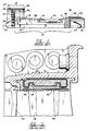
- FIG. 4 there is shown a view similar to that of FIG. 2 but in which the blanket 56 is replaced by a thermal shield 64 comprising a plurality of tubular hexagonal honeycomb cells having radially outward open ends adjacent to the casing 40 and radially inward ends closed by a backing sheet and braze material 66. Also, it is possible to not have a backing so that the biasing means (which is discussed immediately hereafter) contacts the honeycomb cells directly.
- the shield 64 is held in abutting contact with the inner surface of casing 40 by a plurality of resilient biasing means illustrated as a folded leaf spring 68.
- the springs 68 continuously urge the shield 64 against the casing 40 and thus minimize any separation or gap formation between the shield and casing.
- the metal honeycomb heat shield is cut from sheets of commercially available honeycomb material. The sheets are available in various thicknesses and with various honeycomb cell sizes. Certain thickness and cell sizes suitable for the present use are discussed hereinafter.
- the vane liner 48 (FIG. 4) has a plurality of arcuate serpents each supporting a preselected number of nozzle vanes 46. Between each adjacent vane liner serpent there Is the horizontal leaf seal 50, a vertical forward leaf seal (not shown), and a vertical aft leaf seal (not shown). The leaf seals fit in slots in mating surfaces of adjacent vane liners. The leaf seals allow the plurality of vane liners to be connected circumferentially around the engine to form a substantially continuous flow guide for fluid flow through the compressor.
- each vane liner 48 is an arcuate segment of predetermined length supporting a plurality of vanes 46, e.g., eight vanes.
- Each segment of liner 48 is attached to casing 40 by a vane liner retainer 70.
- the vane liner retainer 70 is brazed to vane liner 48 and includes a threaded aperture 72.
- the aperture 72 is aligned with a mating aperture in the casing 40 and a bolt 74 inserted to draw the vane liner 48 into its assembled position with respect to casing 40.
- a shield 64 is inserted between each adjacent retainer 70 so that each shield 64 overlaps adjacent ends of joined vane liners 48.
- Springs 68 are positioned between the shields 64 and vane liners 48 so that the shields are urged against the casing 40.
- the number of springs 68 may be adjusted to provide sufficient force to retain the shields 64.
- Two springs 68 for each shield segment are shown in FIG. 6A.
- a single bow-shaped spring 69 provides the support of the two springs shown in FIG. 6A.
- Spring 69 of FIG. 6B is brazed to backing 66 and makes contact with vane liner 48.
- thermal insulation blankets 56 are used to shield the compressor casing 40 from the flow path of hot gases that leak around the vane retainers 48.
- hot gases can still influence the casing 40 due to gaps between the insulation blanket 56 and casing 40.
- the metal honeycomb cell structure of shields 64 retard the velocity of any gases traversing circumferentially and axially between the casing 40 and shield 64. While the springs 68 keep at least some portions of the shields 64 in contact with the casing 40 inner surface so as to minimize gaps, differential thermal growth and thermal distortion preclude all of the honeycomb cells from being in contact with the casing 12 during all phases of the operation of the engine 10. However, the open ends of the honeycomb cells create a viscous drag which tends to reduce air flow toward zero velocity. The resultant velocity reduction of the hot gas flow over the casing surface reduces the heat transferred to the casing 40 and allows temperatures to be reduced by cooler external (outer surface) air.
- the honeycomb shields 64 preferably have a cell size of 1/4 of an inch and have a ribbon thickness of about .001 inch to about .003 inch.
- the ribbon thickness and cell density reduce surface area for heat conductance. This cell size and ribbon thickness have been found to produce the desired viscous flow effect adjacent the shield surface at the open ends of the cells. Any smaller cell size or thickness makes the surface too uniform to create the desired flow impediment.
- the heat shield 64 of the present invention protects casing 40 from thermal damage
- the springs 68 have been found to dampen shield vibration and thus reduce frictional wear.
- the present invention in maintaining the casing 40 in a cooler state, reduces blade-to-case clearance which in turn improves the performance of the engine.
- the reduced casing temperature achieved with the present invention improves the creep life of the casing thereby maintaining the original manufacturing dimensions for improved engine performance.
Landscapes
- Engineering & Computer Science (AREA)
- Mechanical Engineering (AREA)
- General Engineering & Computer Science (AREA)
- Turbine Rotor Nozzle Sealing (AREA)
- Structures Of Non-Positive Displacement Pumps (AREA)
Abstract
A heat shield mechanism for thermally protecting a casing (40) located in a turbine engine having a plurality of honeycomb cells (64) which are connected to a support plate (66). A spring (68) in contact with the support plate and in contact with a vane liner (48) exerts a force on the support plate which causes at least one of the plurality of honeycomb cells to be pressed against the casing.
Description
- The present invention pertains to heat shields for gas turbine engines and, more particularly, to a heat shield mechanism having a plurality of honeycomb cells aligned in a radially outward manner and which are resiliently biased to maintain at least one honeycomb cell of the plurality of honeycomb cells in contact with an engine casing so as to reduce and eliminate flow gaps between the honeycomb cells and casing.
- In prior art gas turbine engines, thermal insulation blankets have been used to shield compressor casing walls from the flow path of hot gases that leak through the vane retainers after exiting the compressor stage of the engine. These hot gases are known to cause thermal damage to the casing and detrimentally affect engine performance.
- Thus, a need is seen for a heat shield mechanism which can effectively protect the casing wall of a turbine engine from detrimental thermal effects.
- In one aspect, the invention provides a method of assembling a gas turbine engine, the gas turbine engine including a casing defining in part at least one cavity for separating the flow of high energy compressed air from the casing, a thermal shield including a plurality of adjacent honeycomb cells each having an open end and a closed end, the method comprising the steps of :
associating the thermal shield in thermal insulating relation with the casing within the at least one cavity and arranging the thermal shield in engagement with the casing generally about at least some of the open ends of the honeycomb cells with the thermal shield adjacent the closed ends of the honeycomb cells being exposed to the at least one cavity during the associating step; and
resiliently biasing the thermal shield into engagement with the casing to impede and slow down the flow of high energy compressed air. - In a further aspect, the invention provides a gas turbine engine comprising :
a casing defining in part at least one cavity for separating the flow of compressed air within said engine from said casing;
means for thermally insulating said casing within said at least one cavity, said thermally insulating means including a plurality of generally adjacent honeycomb cells each having an open end and a close end, said thermally insulating means being engaged with said casing generally about the open end of at least some of said honeycomb cells and being exposed to said at least one cavity adjacent said closed ends of said honeycomb cells; and
means for resiliently biasing said thermally insulating means into engagement with said casing. - Accordingly, features of the present invention are to provide a novel heat shield mechanism for thermally isolating a casing contained in a turbine engine from leaked hot flow path gases; to improve engine performance by achieving reduced blade-case radial clearance by reducing the casing temperature; and to improve the creep life of the casing flange thereby maintaining the original manufactured dimensions.
- A preferred embodiment provides a heat shield mechanism for thermally protecting a casing located in a turbine engine. The heat shield mechanism comprises a plurality of metal honeycomb cells connected to a support plate. The plurality of honeycomb cells is aligned in a radially outward manner. Resilient biasing means such as a spring acts as a gap reducing means and continuously urges the heat shield radially outward into engagement with an adjacent inner surface of the casing. The spring exerts a force on the honeycomb cells causing them to be in proximate contact with the casing of the turbine engine. Thus, flow gaps are eliminated and dead air spaces created reducing thermal damage to the engine components and operation of the engine are avoided.
- A more complete appreciation of the invention and many of the attendant advantages thereof will be readily obtained as the same becomes better understood by reference to the following detailed description when considered in connection with the accompanying drawings wherein:
- FIG. 1 is a partial cross-sectional illustration of an exemplary high-bypass ratio gas turbine engine;
- FIG. 2 is a schematic cross-sectional view of a prior art compressor case and surrounding structure;
- FIG. 3 is an exemplary schematic illustration of the axial and circumferential air flow which occurs between the casing wall and insulation blankets of prior art turbine engines;
- FIG. 4 is a schematic cross-sectional illustration of the honeycomb support plate and radial spring mechanism in one form of the present invention;
- FIG. 5 is an exploded view depicting the honeycomb cells, support plate, and mounting structure in another form of the present invention;
- FIG. 6A is a simplified schematic illustration depicting the spatial relationships of the honeycomb cells, support plate, and radial springs according to the form of the invention shown in FIG. 5; and
- FIG. 6B illustrates a bow-shaped spring brazed to the backing connected to the heat shield in the form of the present invention shown in FIG. 4.
- When referring to the drawings, it is understood that like reference numerals designate identical or corresponding parts throughout the respective figures.
- Referring first to FIG. 1, there is shown a partial cross-sectional drawing of an exemplary high-bypass ratio
gas turbine engine 10 having a rotor engine portion indicated at 12 and a stator or fan portion indicated at 14. Theengine portion 12 may be referred to as the rotor module. Therotor engine portion 12 includes an intermediate pressure compressor orbooster stage 16, a highpressure compressor stage 18, acombustor stage 20, a highpressure turbine stage 21, and a lowpressure turbine stage 22 all aligned on anengine centerline 23. The engine further includesfan blades 24 and aspinner assembly 28. Thefan portion 14 comprises fan cowling 27 andfan casing 26. The fan cowling 27 surrounds thefan casing 26 and radially encloses the fan portion of theengine 10. - The
fan spinner assembly 28 located forward of thefan blades 24 connects to a rotor assembly (not shown) drivingly coupled toblades 24 and being driven byturbine stage 22. To the aft offan blades 24 is located a plurality of circumferentially spaced outlet guide vanes orfan frame struts 30 which are a part of thefan portion 14. The outlet guide vanes 30 connect theengine portion 12 to the fan portion of theengine 10 and provide structural support. At the rear ofengine 10 is locatedprimary nozzle 33 which includes anouter member 34 and aninner member 35. Thefan shaft 37 driven byturbine stage 22 extends through the engine and is coupled in driving relationship withbooster stage 16 andfan blades 24 via the fan rotor assembly. Theengine portion 12 is positioned in and supported by anouter casing 38. - FIG. 2 is an enlarged view of a portion of
engine 10 adjacent a radially outer circumference of a priorart compressor case 40, a forward row ofblades 42, an aft row ofblades 44, and anintermediate nozzle vane 46. Avane liner 48 extends circumferentially aboutengine 10 and supports a plurality of spacedvanes 46 while providing a radially outer sealing surface for fluid flow throughblades vane 46. Thevane liner 48 generally comprises a plurality of arcuate segments each supporting a preselected number ofnozzle vanes 46. Between each adjacent vane liner segment is ahorizontal leaf seal 50. Between theliner 48 and thecasing 40 is aninsulation blanket 56 which insulates thecompressor case 40 from the hot fluid flow within the compressor. - During engine operation, temperature changes and temperature differentials combined with different thermal growth rates for various engine components causes separation of the various components such that gaps are created which allow air to enter into sundry spaces between components, such as, for example, the
space 41 between thecasing 40 andvane liner 48. Within the compressor stage, pressure increases from an axial forward end to an axially aft end, i.e., from left to right in FIG. 2. This same relationship occurs in thespace 41 so that the static air pressure at the axially aft end is higher than the static air pressure at the axially forward end. In addition, the air incavity 41 may have a circumferential pumping flow component induced by rotation and eccentricity ofblades cavity 41. The air in the cavity is generally at a higher temperature than thecasing 40 and thus can contribute to thermal distortion of the casing if allowed to circulate over the casing surface. Theblanket 56 is intended to restrict this flow as well as reduce heat flow by creating a dead air space and thus minimize thermal heating of the casing. - The gaps between
casing 40 andblanket 56 are typically caused by contour discontinuities caused by a lack of compliance in the internal material of the blanket. Gaps between the liners and casing exist due to piece-part tolerance and actually decrease during engine operation. - With reference to FIG. 3, there is illustrated the relationship between the
casing 40 andinsulation blanket 56 following engine operation which demonstrates the problem inherent in the use of prior art insulation blankets comprised of fibrous material. Engine vibration, thermal cycling, and installation deformation cause the fibrous material to shift creating gaps between theblanket 56 and adjacent portions ofcasing 40. This shifting and surface discontinuities create agap 58 which allows axial air flow, indicated byarrow 60, and circumferential air flow, indicated byarrow 62, to flow unobstructed with increased velocity resulting in undesirable heating of thecasing 40 and detrimentally affecting engine performance. It is therefore desirable to provide a method and apparatus for insulatingcasing 40 from such hot fluid and parasitic leakage, and which eliminate convective heat transfer even when the insulation means is not in intimate contact with the casing. - With reference to FIG. 4, there is shown a view similar to that of FIG. 2 but in which the
blanket 56 is replaced by athermal shield 64 comprising a plurality of tubular hexagonal honeycomb cells having radially outward open ends adjacent to thecasing 40 and radially inward ends closed by a backing sheet andbraze material 66. Also, it is possible to not have a backing so that the biasing means (which is discussed immediately hereafter) contacts the honeycomb cells directly. Theshield 64 is held in abutting contact with the inner surface of casing 40 by a plurality of resilient biasing means illustrated as a foldedleaf spring 68. Thesprings 68 continuously urge theshield 64 against thecasing 40 and thus minimize any separation or gap formation between the shield and casing. The metal honeycomb heat shield is cut from sheets of commercially available honeycomb material. The sheets are available in various thicknesses and with various honeycomb cell sizes. Certain thickness and cell sizes suitable for the present use are discussed hereinafter. - As in FIG. 2, the vane liner 48 (FIG. 4) has a plurality of arcuate serpents each supporting a preselected number of
nozzle vanes 46. Between each adjacent vane liner serpent there Is thehorizontal leaf seal 50, a vertical forward leaf seal (not shown), and a vertical aft leaf seal (not shown). The leaf seals fit in slots in mating surfaces of adjacent vane liners. The leaf seals allow the plurality of vane liners to be connected circumferentially around the engine to form a substantially continuous flow guide for fluid flow through the compressor. - With reference to FIGS. 5 and 6A, there is shown one arrangement for positioning and supporting the metallic
honeycomb heat shields 64 above thevane liner 48. For purposes of simplifying the illustration, only limited segments of the honeycomb shields 64 are shown in FIG. 5. Eachvane liner 48 is an arcuate segment of predetermined length supporting a plurality ofvanes 46, e.g., eight vanes. Each segment ofliner 48 is attached to casing 40 by avane liner retainer 70. Thevane liner retainer 70 is brazed tovane liner 48 and includes a threadedaperture 72. Theaperture 72 is aligned with a mating aperture in thecasing 40 and a bolt 74 inserted to draw thevane liner 48 into its assembled position with respect tocasing 40. Ashield 64 is inserted between eachadjacent retainer 70 so that eachshield 64 overlaps adjacent ends of joinedvane liners 48. - Testing has shown that the overlap acts as an inhibitor to radial impingement of gases on the casing.
Springs 68 are positioned between theshields 64 andvane liners 48 so that the shields are urged against thecasing 40. The number ofsprings 68 may be adjusted to provide sufficient force to retain theshields 64. Two springs 68 for each shield segment are shown in FIG. 6A. Alternatively, in the embodiment illustrated in FIG. 6B, a single bow-shaped spring 69 provides the support of the two springs shown in FIG. 6A. Spring 69 of FIG. 6B is brazed to backing 66 and makes contact withvane liner 48. - In the prior art system of FIG. 2, thermal insulation blankets 56 are used to shield the
compressor casing 40 from the flow path of hot gases that leak around thevane retainers 48. However, as explained with respect to FIG. 3, hot gases can still influence thecasing 40 due to gaps between theinsulation blanket 56 andcasing 40. - The metal honeycomb cell structure of
shields 64 retard the velocity of any gases traversing circumferentially and axially between thecasing 40 andshield 64. While thesprings 68 keep at least some portions of theshields 64 in contact with thecasing 40 inner surface so as to minimize gaps, differential thermal growth and thermal distortion preclude all of the honeycomb cells from being in contact with thecasing 12 during all phases of the operation of theengine 10. However, the open ends of the honeycomb cells create a viscous drag which tends to reduce air flow toward zero velocity. The resultant velocity reduction of the hot gas flow over the casing surface reduces the heat transferred to thecasing 40 and allows temperatures to be reduced by cooler external (outer surface) air. - The honeycomb shields 64 preferably have a cell size of 1/4 of an inch and have a ribbon thickness of about .001 inch to about .003 inch. The ribbon thickness and cell density reduce surface area for heat conductance. This cell size and ribbon thickness have been found to produce the desired viscous flow effect adjacent the shield surface at the open ends of the cells. Any smaller cell size or thickness makes the surface too uniform to create the desired flow impediment.
- While the
heat shield 64 of the present invention protects casing 40 from thermal damage, thesprings 68 have been found to dampen shield vibration and thus reduce frictional wear. Furthermore, the present invention, in maintaining thecasing 40 in a cooler state, reduces blade-to-case clearance which in turn improves the performance of the engine. Still further, the reduced casing temperature achieved with the present invention improves the creep life of the casing thereby maintaining the original manufacturing dimensions for improved engine performance. - The foregoing detailed description is intended to be illustrative and non-limiting. Many changes and modifications are possible in light of the above teachings. Thus, it is understood that the invention may be practiced otherwise than as specifically described herein and still be within the scope of the appended claims.
Claims (7)
- A method of assembling a gas turbine engine, the gas turbine engine including a casing defining in part at least one cavity for separating the flow of high energy compressed air from the casing, a thermal shield including a plurality of adjacent honeycomb cells each having an open end and a closed end, the method comprising the steps of:
associating the thermal shield in thermal insulating relation with the casing within the at least one cavity and arranging the thermal shield in engagement with the casing generally about at least some of the open ends of the honeycomb cells with the thermal shield adjacent the closed ends of the honeycomb cells being exposed to the at least one cavity during the associating step; and
resiliently biasing the thermal shield into engagement with the casing to impede and slow down the flow of high energy compressed air. - A method of insulating a casing structure in a gas turbine engine from a high energy working medium flow, the method comprising the steps of:
spacing at least part of the casing from the high energy flow with at least one cavity adjacent the casing; and
supporting a multi-celled insulator structure in the cavity with at least some of the multiple cells having open ends facing the casing. - A gas turbine engine comprising:
a casing defining in part at least one cavity for separating the flow of compressed air within said engine from said casing;
means for thermally insulating said casing within said at least one cavity, said thermally insulating means including a plurality of generally adjacent honeycomb cells each having an open end and a closed end, said thermally insulating means being engaged with said casing generally about the open end of at least some of said honeycomb cells and being exposed to said at least one cavity adjacent said closed ends of said honeycomb cells; and
means for resiliently biasing said thermally insulating means into engagement with said casing. - The gas turbine as set forth in claim 3 wherein said resiliently biasing means comprises spring means associated with said thermal insulating means for maintaining said thermally insulating means in a preselected position within said at least one cavity with respect to said casing.
- The gas turbine as set forth in claim 3 wherein said closed ends of said honeycomb cells define a generally uniform surface exposed to said at least one cavity.
- The gas turbine as set forth in claim 3 wherein said open ends of others of said honeycomb cells in said thermally insulating means are displaced from said casing in response to thermal distortion of at least one of said casing and said others of said honeycomb cells.
- The gas turbine as set forth in claim 3 wherein said thermally insulating means further includes means associated therewith for closing said closed ends of said honeycomb cells and for presenting a generally uniform surface to said at least one passage means.
Applications Claiming Priority (2)
| Application Number | Priority Date | Filing Date | Title |
|---|---|---|---|
| US727186 | 1991-07-09 | ||
| US07/727,186 US5195868A (en) | 1991-07-09 | 1991-07-09 | Heat shield for a compressor/stator structure |
Publications (1)
| Publication Number | Publication Date |
|---|---|
| EP0522833A1 true EP0522833A1 (en) | 1993-01-13 |
Family
ID=24921678
Family Applications (1)
| Application Number | Title | Priority Date | Filing Date |
|---|---|---|---|
| EP92306243A Withdrawn EP0522833A1 (en) | 1991-07-09 | 1992-07-07 | Heat shield for a compressor stator structure |
Country Status (4)
| Country | Link |
|---|---|
| US (1) | US5195868A (en) |
| EP (1) | EP0522833A1 (en) |
| JP (1) | JPH06105052B2 (en) |
| CA (1) | CA2070521A1 (en) |
Cited By (5)
| Publication number | Priority date | Publication date | Assignee | Title |
|---|---|---|---|---|
| WO2003006799A1 (en) * | 2001-07-12 | 2003-01-23 | Alstom Technology Ltd. | Insulating device and assembly method |
| WO2011106121A1 (en) * | 2010-02-25 | 2011-09-01 | General Electric Company | Turbine shroud support thermal shield |
| EP2826959A3 (en) * | 2013-07-15 | 2015-03-25 | MTU Aero Engines GmbH | Method for producing an insulation element and insulating element for a housing of an aircraft engine |
| EP3181828A1 (en) * | 2015-12-17 | 2017-06-21 | United Technologies Corporation | Blade outer air seal with integrated air shield |
| DE102023128456A1 (en) * | 2023-10-17 | 2025-04-17 | MTU Aero Engines AG | Guide vane, guide vane cluster and casing for a gas turbine and gas turbine |
Families Citing this family (24)
| Publication number | Priority date | Publication date | Assignee | Title |
|---|---|---|---|---|
| US5562408A (en) * | 1995-06-06 | 1996-10-08 | General Electric Company | Isolated turbine shroud |
| US6042334A (en) * | 1998-08-17 | 2000-03-28 | General Electric Company | Compressor interstage seal |
| US6786052B2 (en) * | 2002-12-06 | 2004-09-07 | 1419509 Ontario Inc. | Insulation system for a turbine and method |
| US7618234B2 (en) * | 2007-02-14 | 2009-11-17 | Power System Manufacturing, LLC | Hook ring segment for a compressor vane |
| US7766609B1 (en) | 2007-05-24 | 2010-08-03 | Florida Turbine Technologies, Inc. | Turbine vane endwall with float wall heat shield |
| US8092161B2 (en) * | 2008-09-24 | 2012-01-10 | Siemens Energy, Inc. | Thermal shield at casing joint |
| FR2964145B1 (en) * | 2010-08-26 | 2018-06-15 | Safran Helicopter Engines | TURBINE HOOD SHIELDING METHOD AND HITCH ASSEMBLY FOR ITS IMPLEMENTATION |
| US9115600B2 (en) | 2011-08-30 | 2015-08-25 | Siemens Energy, Inc. | Insulated wall section |
| US9322415B2 (en) | 2012-10-29 | 2016-04-26 | United Technologies Corporation | Blast shield for high pressure compressor |
| US9714611B2 (en) | 2013-02-15 | 2017-07-25 | Siemens Energy, Inc. | Heat shield manifold system for a midframe case of a gas turbine engine |
| EP2853685A1 (en) * | 2013-09-25 | 2015-04-01 | Siemens Aktiengesellschaft | Insert element and gas turbine |
| DE102015215144B4 (en) * | 2015-08-07 | 2017-11-09 | MTU Aero Engines AG | Device and method for influencing the temperatures in inner ring segments of a gas turbine |
| US10132184B2 (en) * | 2016-03-16 | 2018-11-20 | United Technologies Corporation | Boas spring loaded rail shield |
| US10161258B2 (en) * | 2016-03-16 | 2018-12-25 | United Technologies Corporation | Boas rail shield |
| US10138749B2 (en) | 2016-03-16 | 2018-11-27 | United Technologies Corporation | Seal anti-rotation feature |
| US10371005B2 (en) | 2016-07-20 | 2019-08-06 | United Technologies Corporation | Multi-ply heat shield assembly with integral band clamp for a gas turbine engine |
| US11125092B2 (en) * | 2018-08-14 | 2021-09-21 | Raytheon Technologies Corporation | Gas turbine engine having cantilevered stators |
| FR3086323B1 (en) * | 2018-09-24 | 2020-12-11 | Safran Aircraft Engines | INTERNAL TURMOMACHINE HOUSING WITH IMPROVED THERMAL INSULATION |
| US11371375B2 (en) * | 2019-08-19 | 2022-06-28 | Raytheon Technologies Corporation | Heatshield with damper member |
| CN113006483B (en) * | 2021-02-01 | 2022-09-02 | 广州景翔建筑工程有限公司 | Be used for building steel form release agent to paint device |
| US11674396B2 (en) | 2021-07-30 | 2023-06-13 | General Electric Company | Cooling air delivery assembly |
| US11674405B2 (en) | 2021-08-30 | 2023-06-13 | General Electric Company | Abradable insert with lattice structure |
| CN113846839B (en) * | 2021-10-26 | 2023-11-24 | 惠州市航丰木业有限公司 | Equipment is paintd to building templates release agent |
| CN120867841B (en) * | 2025-09-28 | 2025-12-09 | 中国空气动力研究与发展中心空天技术研究所 | Low-conductance-free multifunctional contra-rotating turbine structure |
Citations (1)
| Publication number | Priority date | Publication date | Assignee | Title |
|---|---|---|---|---|
| GB2115487A (en) * | 1982-02-19 | 1983-09-07 | Gen Electric | Double wall compressor casing |
Family Cites Families (14)
| Publication number | Priority date | Publication date | Assignee | Title |
|---|---|---|---|---|
| US3365172A (en) * | 1966-11-02 | 1968-01-23 | Gen Electric | Air cooled shroud seal |
| US3423070A (en) * | 1966-11-23 | 1969-01-21 | Gen Electric | Sealing means for turbomachinery |
| US3656862A (en) * | 1970-07-02 | 1972-04-18 | Westinghouse Electric Corp | Segmented seal assembly |
| US3728041A (en) * | 1971-10-04 | 1973-04-17 | Gen Electric | Fluidic seal for segmented nozzle diaphragm |
| US3970319A (en) * | 1972-11-17 | 1976-07-20 | General Motors Corporation | Seal structure |
| GB1483532A (en) * | 1974-09-13 | 1977-08-24 | Rolls Royce | Stator structure for a gas turbine engine |
| GB1501916A (en) * | 1975-06-20 | 1978-02-22 | Rolls Royce | Matching thermal expansions of components of turbo-machines |
| US4087199A (en) * | 1976-11-22 | 1978-05-02 | General Electric Company | Ceramic turbine shroud assembly |
| US4309145A (en) * | 1978-10-30 | 1982-01-05 | General Electric Company | Cooling air seal |
| DE8013163U1 (en) * | 1980-05-16 | 1988-10-13 | MTU Motoren- und Turbinen-Union München GmbH, 8000 München | Housing for a thermal turbomachine with a heat-insulating lining |
| US4398866A (en) * | 1981-06-24 | 1983-08-16 | Avco Corporation | Composite ceramic/metal cylinder for gas turbine engine |
| US4525998A (en) * | 1982-08-02 | 1985-07-02 | United Technologies Corporation | Clearance control for gas turbine engine |
| FR2548733B1 (en) * | 1983-07-07 | 1987-07-10 | Snecma | DEVICE FOR SEALING MOBILE BLADES OF A TURBOMACHINE |
| US4826397A (en) * | 1988-06-29 | 1989-05-02 | United Technologies Corporation | Stator assembly for a gas turbine engine |
-
1991
- 1991-07-09 US US07/727,186 patent/US5195868A/en not_active Expired - Fee Related
-
1992
- 1992-06-04 CA CA002070521A patent/CA2070521A1/en not_active Abandoned
- 1992-07-07 EP EP92306243A patent/EP0522833A1/en not_active Withdrawn
- 1992-07-08 JP JP4180672A patent/JPH06105052B2/en not_active Expired - Lifetime
Patent Citations (1)
| Publication number | Priority date | Publication date | Assignee | Title |
|---|---|---|---|---|
| GB2115487A (en) * | 1982-02-19 | 1983-09-07 | Gen Electric | Double wall compressor casing |
Cited By (8)
| Publication number | Priority date | Publication date | Assignee | Title |
|---|---|---|---|---|
| WO2003006799A1 (en) * | 2001-07-12 | 2003-01-23 | Alstom Technology Ltd. | Insulating device and assembly method |
| WO2011106121A1 (en) * | 2010-02-25 | 2011-09-01 | General Electric Company | Turbine shroud support thermal shield |
| EP2826959A3 (en) * | 2013-07-15 | 2015-03-25 | MTU Aero Engines GmbH | Method for producing an insulation element and insulating element for a housing of an aircraft engine |
| US9726038B2 (en) | 2013-07-15 | 2017-08-08 | MTU Aero Engines AG | Method of producing an insulation element and insulation element for a housing of an aero engine |
| EP3181828A1 (en) * | 2015-12-17 | 2017-06-21 | United Technologies Corporation | Blade outer air seal with integrated air shield |
| US10443426B2 (en) | 2015-12-17 | 2019-10-15 | United Technologies Corporation | Blade outer air seal with integrated air shield |
| DE102023128456A1 (en) * | 2023-10-17 | 2025-04-17 | MTU Aero Engines AG | Guide vane, guide vane cluster and casing for a gas turbine and gas turbine |
| EP4542007A1 (en) * | 2023-10-17 | 2025-04-23 | MTU Aero Engines AG | Guide vane for a gas turbine, guide vane cluster for a gas turbine, casing for a gas turbine, and gas turbine |
Also Published As
| Publication number | Publication date |
|---|---|
| CA2070521A1 (en) | 1993-01-10 |
| US5195868A (en) | 1993-03-23 |
| JPH06105052B2 (en) | 1994-12-21 |
| JPH05187261A (en) | 1993-07-27 |
Similar Documents
| Publication | Publication Date | Title |
|---|---|---|
| US5195868A (en) | Heat shield for a compressor/stator structure | |
| US11725823B2 (en) | Mounting a ceramic component to a non-ceramic component in a gas turbine engine | |
| US5174714A (en) | Heat shield mechanism for turbine engines | |
| EP0616113B1 (en) | Gas turbine engine and method of assembling a seal in said gas turbine engine | |
| EP1240411B1 (en) | Split ring for tip clearance control | |
| EP2278125B1 (en) | Turbine nozzle assembly including radially-compliant spring member for gas turbine engine | |
| KR100379728B1 (en) | Rotor assembly shroud | |
| US9810097B2 (en) | Corrugated mid-turbine frame thermal radiation shield | |
| US20100054928A1 (en) | Gas turbine transition duct apparatus | |
| GB2228539A (en) | Stator assembly for a rotary machine | |
| US5238365A (en) | Assembly for thermal shielding of low pressure turbine | |
| JPH0713471B2 (en) | Liner segment positioning system and system for preventing recirculation leakage between compressor liner segments | |
| EP0522795B1 (en) | Heat shield | |
| US12140229B2 (en) | Non-contact seal assembly with multiple spaced spring elements | |
| US7958735B2 (en) | Turbine static structure for reduced leakage air | |
| CN117222800A (en) | Turbine ring assembly mounted on cross member | |
| JPH09329003A (en) | Turbine shroud with gas sealing device | |
| US20230203954A1 (en) | Turbine blade |
Legal Events
| Date | Code | Title | Description |
|---|---|---|---|
| PUAI | Public reference made under article 153(3) epc to a published international application that has entered the european phase |
Free format text: ORIGINAL CODE: 0009012 |
|
| AK | Designated contracting states |
Kind code of ref document: A1 Designated state(s): DE FR GB IT |
|
| 17P | Request for examination filed |
Effective date: 19930701 |
|
| 17Q | First examination report despatched |
Effective date: 19941123 |
|
| GRAH | Despatch of communication of intention to grant a patent |
Free format text: ORIGINAL CODE: EPIDOS IGRA |
|
| STAA | Information on the status of an ep patent application or granted ep patent |
Free format text: STATUS: THE APPLICATION IS DEEMED TO BE WITHDRAWN |
|
| 18D | Application deemed to be withdrawn |
Effective date: 19970201 |