EP0520766B1 - Innate bus monitor for computer system manager - Google Patents
Innate bus monitor for computer system manager Download PDFInfo
- Publication number
- EP0520766B1 EP0520766B1 EP92305798A EP92305798A EP0520766B1 EP 0520766 B1 EP0520766 B1 EP 0520766B1 EP 92305798 A EP92305798 A EP 92305798A EP 92305798 A EP92305798 A EP 92305798A EP 0520766 B1 EP0520766 B1 EP 0520766B1
- Authority
- EP
- European Patent Office
- Prior art keywords
- address
- signals
- data
- manager
- data signals
- Prior art date
- Legal status (The legal status is an assumption and is not a legal conclusion. Google has not performed a legal analysis and makes no representation as to the accuracy of the status listed.)
- Expired - Lifetime
Links
Images




Classifications
-
- G—PHYSICS
- G06—COMPUTING OR CALCULATING; COUNTING
- G06F—ELECTRIC DIGITAL DATA PROCESSING
- G06F11/00—Error detection; Error correction; Monitoring
- G06F11/30—Monitoring
- G06F11/34—Recording or statistical evaluation of computer activity, e.g. of down time, of input/output operation ; Recording or statistical evaluation of user activity, e.g. usability assessment
- G06F11/3466—Performance evaluation by tracing or monitoring
- G06F11/349—Performance evaluation by tracing or monitoring for interfaces, buses
-
- G—PHYSICS
- G06—COMPUTING OR CALCULATING; COUNTING
- G06F—ELECTRIC DIGITAL DATA PROCESSING
- G06F11/00—Error detection; Error correction; Monitoring
- G06F11/30—Monitoring
- G06F11/3003—Monitoring arrangements specially adapted to the computing system or computing system component being monitored
- G06F11/3027—Monitoring arrangements specially adapted to the computing system or computing system component being monitored where the computing system component is a bus
-
- G—PHYSICS
- G06—COMPUTING OR CALCULATING; COUNTING
- G06F—ELECTRIC DIGITAL DATA PROCESSING
- G06F11/00—Error detection; Error correction; Monitoring
- G06F11/30—Monitoring
- G06F11/3065—Monitoring arrangements determined by the means or processing involved in reporting the monitored data
- G06F11/3072—Monitoring arrangements determined by the means or processing involved in reporting the monitored data where the reporting involves data filtering, e.g. pattern matching, time or event triggered, adaptive or policy-based reporting
-
- G—PHYSICS
- G06—COMPUTING OR CALCULATING; COUNTING
- G06F—ELECTRIC DIGITAL DATA PROCESSING
- G06F11/00—Error detection; Error correction; Monitoring
- G06F11/30—Monitoring
- G06F11/34—Recording or statistical evaluation of computer activity, e.g. of down time, of input/output operation ; Recording or statistical evaluation of user activity, e.g. usability assessment
- G06F11/3466—Performance evaluation by tracing or monitoring
-
- G—PHYSICS
- G06—COMPUTING OR CALCULATING; COUNTING
- G06F—ELECTRIC DIGITAL DATA PROCESSING
- G06F11/00—Error detection; Error correction; Monitoring
- G06F11/30—Monitoring
- G06F11/34—Recording or statistical evaluation of computer activity, e.g. of down time, of input/output operation ; Recording or statistical evaluation of user activity, e.g. usability assessment
- G06F11/3466—Performance evaluation by tracing or monitoring
- G06F11/3471—Address tracing
-
- G—PHYSICS
- G06—COMPUTING OR CALCULATING; COUNTING
- G06F—ELECTRIC DIGITAL DATA PROCESSING
- G06F11/00—Error detection; Error correction; Monitoring
- G06F11/30—Monitoring
- G06F11/34—Recording or statistical evaluation of computer activity, e.g. of down time, of input/output operation ; Recording or statistical evaluation of user activity, e.g. usability assessment
- G06F11/3466—Performance evaluation by tracing or monitoring
- G06F11/3476—Data logging
-
- G—PHYSICS
- G06—COMPUTING OR CALCULATING; COUNTING
- G06F—ELECTRIC DIGITAL DATA PROCESSING
- G06F11/00—Error detection; Error correction; Monitoring
- G06F11/30—Monitoring
- G06F11/34—Recording or statistical evaluation of computer activity, e.g. of down time, of input/output operation ; Recording or statistical evaluation of user activity, e.g. usability assessment
- G06F11/3466—Performance evaluation by tracing or monitoring
- G06F11/3495—Performance evaluation by tracing or monitoring for systems
Definitions
- the invention relates to a innate monitoring system for a computer system manager, and, more particularly to a innate monitoring system for a system manager which monitors information transfer along a system bus of the computer system.
- a LAN is a system of computer hardware and software that links components such as computers, printers and other peripherals into a network suitable for transmission between various ones of the linked components located in relative proximity to each other, for example in different offices in a building, or in different buildings situated near one another.
- WAN wide area network
- a WAN differs from a LAN in that a telephone network is also required to link at least some of the components included in the network to the remainder of the network components.
- network operating systems are in existence today. They include the NetWare system manufactured by Novell, Inc. of Provo, Utah, the VINES system manufactured by Banyan, and the LAN Manager system manufactured by Microsoft Corporation of Redmond, Washington. While such network operating systems often include a network manager, the network manager included in such systems have typically relied upon the network operating system to provide data to the network manager for performing network management functions. Since network managers have been forced to rely upon data transmitted by the network, prior network managers have focused on analyzing the health of the network and have not been particularly well suited to analyze the health of the components of the network.
- network managers have been best equipped to performing configuration and security management.
- Network managers can also provide limited fault analysis, but, in most cases, only after failure has occured.
- LAN and WAN which include multiple printer, communication, database, and file server locations have been contemplated. This drive towards combining increasing numbers of computer components into a single network, has let to an increased demand for greater management capabilities. While, in the past, failure alerts may have been satisfactory, there is an increasing demand for information that will lead to failure whereby potentiat failures may be reported in sufficient time to allow for corrective action before an actual failure occurs.
- the present invention is a monitoring system for monitoring a computer system including a system bus, the monitoring system comprising:
- the computer network 10 which may be configured as either a LAN, WAN, or other type of network configuration, includes an EISA server 12, for example, a Systempro Model 486-840 manufactured by Compaq Computer Corp. of Houston, Texas, having an EISA based computer system board comprised of a series of computer subsystems (not shown) interconnected by a EISA based system bus.
- EISA server 12 for example, a Systempro Model 486-840 manufactured by Compaq Computer Corp. of Houston, Texas, having an EISA based computer system board comprised of a series of computer subsystems (not shown) interconnected by a EISA based system bus.
- EISA computer system board and EISA system bus are, for ease of illustration, indicated as a unified element, EISA system board/bus 13, although all specific references to such element shall specifically indicate which portion of the unified element is being considered in such reference.
- Installed on the EISA computer system board 13 are a plurality of cards which include the system manager 22, which, as will be more fully described below, is comprised of a 32 bit intelligent bus master board and supporting firmware, an EISA network interface adapter 24 and an intelligent disk array controller device 26.
- Installed in the operating system (or "OS") section of the EISA server 12 is a network operating system 14, preferably one which includes a network management agent 15. It is comtemplated that any one of numerous network operating systems, for example, the NetWare or LAN Manager network operating systems previously described, would be suitable for use as the network operating system 14.
- the system manager device driver 16 acts as a bi-directional translator for all requests to and from the system manager 22, thereby providing two-way communication between the system manager 22 and the network management agent 15.
- the network management agent 15 may supply information to or receive information collected by the system manager 22.
- Object management by the system manager 22 may, therefore, be initiated by the network management agent 15 if the network management agent 15 issues instructions to create, delete, modify, reset, or clear objects stored in the system manager 22.
- the system manager device driver 16 will also handle certain in-band and out-of band alerts. If generated by the system manager 22, an in-band alert will be transmitted by the system manager device driver 16 to the network operating system 14 which, under the control of the network management agent 15, will direct the in-band alert to a local network manager console 36 connected to the network operating system 14 by in-band network bus 42. Out-of-band alerts generated by the network operating system 14, on the other hand, will be transmitted by the system manager device driver 16 to the system manager 22 for transmission to a remotely located system manager facility 34 connected to the system manager 22 via an asynchronous link 40, for example, a telephone connection. Two-way communication between the system manager 22 and the remotely located system manager console is provided by a system facility device driver 38. While there are additional signals transmitted between the system manager 22 and the network operating system 14 by the system manager device driver 16, these additional signals shall be discussed in greater detail later.
- the network management agent 15 also operates as a central collection point for network management information for the EISA server 12 by acting as a link between the system manager 22, other cards installed on the computer system board 13, and the computer network itself.
- an EISA network interface adapter 24 for example, a Model NE3200 32-bit Ethernet adapter manufactured by Anthem Electonics, Inc.
- an intelligent disk array controller device 26 are also installed on the computer system board 13.
- the network operating system 14 connects the computer system board 13 and, via a network interface device driver 18 which operates in a manner similar to the system manager device driver 16, the network interface adapter 24 for two-way data transmission therebetween.
- the network interface adapter 24 is connected for two-way data transmission with the network 28, a two-way communication link between the system manager 22 and the network 28 is thus provided.
- the network 28 is the interface of the netwwork components via the network media.
- the network 28 may be configured in a token ring, Ethernet, or other network topology in use today, to control the access of multiple computer stations to the network 28, although, in the embodiment of the invention described and illustrated herein, a single computer station 30 has been provided.
- An intelligent disk array controller device driver 20 which, like the network interface device driver 18, operates in a manner similar to the system manager device driver 16, provides for two-way data transmission between the system manager 22 and, via the network operating system, the intelligent disk array controller device 26.
- the intelligent disk array controller device 26 provides disk storage for the computer system board 13.
- the intelligent disk array (or "IDA") controller device 26 may provide 840 Mbytes of disk storage for the computer system board 13 by associating four 210M-byte Compaq IDA drive pairs therewith.
- the system manager 22 has the ability to monitor various system components and parameters. If a component experiences a failure or exhibits characteristics that indicate it may experience a failure, the system manager 22 detects the failure or characteristic indicative of a potential failure and reports the failure or characteristic indicative of a potential failure as an alert in a manner such that corrective action can be taken.
- the path by which data accumulated during the monitoring of system components and parameters indicative of an actual or potential failure may be any one of four paths, depending on the particular type of actual or potential failure being monitored.
- Each system component being monitored may be referred to as an object having a number of attributes.
- the value of the object's attributes may change, for example, by incrementing, decrementing, updating, resetting or modifying. When the attributes exceed their boundary or threshold value, an alert will be generated.
- the attributes of objects may be utilized to provide continuous real-time monitoring of the computer system board 13 without interfering with normal system operations.
- the computer system bus 13 supplies certain signals to a bus monitor 44 which will help determine the state of the computer system board 13.
- signals include interrupt request (or "IRQ") signals, data memory request (or “DRQ”) signals and input/output (or "I/O") signals.
- IRQ interrupt request
- DRQ data memory request
- I/O input/output
- the bus monitor 44 monitors the I/O signals although, in a further embodiment of the invention, it is contemplated that the bus monitor 44 monitors the supplied IRQ, DRQ and I/O signals. If the signals are active, then the corresponding system resources are being used. In this manner, these signals may be used to monitor the performance of the computer system board 13.
- Other signals supplied by the computer system bus 13, are utilized during object management to indicate alert conditions.
- the absence of the refresh signal will generate an alert since the lack of refresh may cause the file server 12 to fail.
- an indication of a memory parity error will cause the generation of an alert.
- the printer port so that the system manager 22 can report whether or not there is a printer error or is out of paper
- the asynchronous serial port so that the system manager can monitor and log ansynchronous activity such as overrun errors, parity errors, and framing errors for system board serial ports, system software, so that software errors can be identified, and keyboard events, so that keystrokes can be logged and the relationship between a system failure and keyboard inputs can be analyzed.
- the bus monitor 44 will detect the assertion of IOCHK, indicative of a catastrophic board failure, and board "times out", indicative of a violation of EISA standards.
- the bus monitor 44 transfers these signals to information processing and alert determination elements 52 where the monitored information is processed.
- the information processing and alert determination elements 52 of the system manager 22 is comprised of a control processor and supporting logic which, by the application of object management techniques, is configured to determine whether the monitored information warrants the generation of an alert.
- the system manager 22 further provides for the monitoring of other signals for delivery to the information processing and alert determination elements 52 for potential generation of alerts. These other signals are supplied to the information processing and alert determination elements 52 by a path distinct from that previously discussed.
- the computer system bus 13 provides ⁇ 5 Volt and ⁇ 12 Volt lines to a power-temperature monitor/power supply elements 50.
- the level of voltage supplied to the system manager 22 is converted into a digital signal by an analog-to-digital converter included in the power-temperature monitor/power supply elements 50 and the digital power level signal is provided to the information processing and alert determination elements 52. For example, if a drop in system power is detected, the information processing and alert determination elements 52 will generate an alert.
- the system manager 22 will switch to battery power and the event reported, again as an alert, through one or both of its asynchronous modem and serial connections. Briefly, however, after loss of system power, the system manager will switch into reserve power to deliver alerts and, after completing alert delivery, to standby mode to conserve power. After reserve power is exhausted, the system manager then switches into dormant mode to keep its RAM memory valid for an extended period of time and, after the expiration of the extended period of time, cutting power off completely.
- the system manager 22 is further provided with a temperature sensor 48.
- the internal temperature of the system manager 22 is continuously monitored by the temperature sensor 48 and the measured temperature transmitted to power-temperature monitor/power supply elements 50 where analog to digital conversion of the monitored temparature is performed.
- the digital temperature level is then transmitted to information processing and alert determination elements 52 for object management. If the information processing and alert determination elements 52 determine that the temperature has risen above a predetermined threshold, then an alert may be issued.
- a bus master interface 46 is used to transfer certain signals from the network operating system 14 to the information processing and alert determination elements 52.
- the information provided by the bus master interface 46 differs from that passively supplied by the bus monitor 44 or the power-temperature monitor/power supply elements 50 in that information supplied via the bus master interface 46 are supplied as hard inputs.
- the system manager 22 can monitor network resources other than the computer system board 13 itself.
- the intelligent disk array controller device 26 would provide management information to the network management agent 15 such as the number of read errors that have occurred.
- the network management agent 15 can provide that information to the system manager 22 via the bus master interface 46.
- the information passively monitored by the bus monitor 44 and the power-temperature monitor portion of the power-temperature monitor/power supply elements 50 and supplied to the information processing and alert determination elements 52, as well as that information supplied to the information processing and alert determination elements 52 by the bus master interface 46 may be used for several purposes.
- the information processing and alert determination elements 52 can process the information and, if appropriate, generate an alert. Examples of alert conditions that may be determined by information processing and alert determination elements 52 include loss of system power, server subsystem failure, excessive server temperature as well as other configurable events that require outside attention.
- an alert can be issued in a number of ways. Initially, it must be determined if the alert should be delivered "in-band” or "out-of-band". Once originated by the information processing and alert determination elements 52, an in-band alert is directed to the bus master interface 46 and on to the network operating system 14 and, under the control of the network management software contained in the network management agent 15, on to the local network manager console 36. So that the use of existing network hardware is maximized, it is contemplated that in-band alerts to the local network manager console 36 will be utilized as the primary path for communications with the system manager 22.
- a local system manager console may be used to receive in-band alerts without departing from the practice of the present invention. If the information processing and alert determination elements 52 determine that the alert should be issued "out-of-band", the alert is transmitted to communication elements 54 where an alert is issued.
- the communication elements may send an out-of-band alert by sending a protocol message over a switched telephone connection to the system manager facility 34, by dialling a phone number associated with a pager 56 or by dialing a phone number to a phone 58 associated with a person and generating a synthesized voice message upon completing a connection with the phone 58.
- the information processing and alert determination elements 52 also perform several other functions. More specifically, the received information is also time stamped and stored or "logged" into RAM memory for later access. Thus, in the event of a catastrophic failure of the file server 12, the monitored and logged information will be available for "post mortem" diagnostics. Similarly, network information may be transferred over the bus master interface 46 and logged into RAM memory contained within the information processing and alert determination elements 52. Finally, the objects can be transferred, for example to the remote system manager facility 34 or the local network manager console 36 to provide real-time information regarding the performance of the system manager 22.
- remote console emulation permits keystrokes at the remote console to be delivered to the system manager 22 as if they were input locally.
- hard key insertion "soft" reboots are emulated by simultaneously inserting "control"--"alt”--"del” to actuate a reboot of the system manager 22. While not being able to actuate a complete "hard” reboot, the system manager facility 34 can simulate a hard reboot by selectively removing power from system components.
- the bus monitor 44 innately monitors a plurality of signals relating to the state of the computer system board 13. Innate monitoring is accomplished by the bus monitor 44 receiving all data and address signals being transferred along the system bus 13.
- the bus monitor 44 will then select those signals which will help determine the state of the computer system board 13 and directs the selected signals via a bus to, what previously was functionally designated as the information processing and alert determination elements 52 and what is now structurally designated as a CPU/memory subsystem 52 which is the hardware which, together with associated firmware, will perform the aforementioned information processing and alert determination functions.
- Other signals indicated here as miscellaneous system signals, are always considered to help determine the state of the computer system board and are directed through the bus monitor 44 to the CPU/memory subsystem 52.
- the system bus 13 supplies power to the system manager 22 via ⁇ 5V, ⁇ 12V lines to the power-temperature monitor/power supply element 50 and on to the CPU/memory subsystem 52.
- the power-temperature monitor/power supply element 50 will begin supplying power from a battery included therein.
- the termination of the supply of power from the system bus will also be reported to the CPU/memory subsystem 52 as an alert condition.
- a modem/asynchronous interface 60 Connected to output of the CPU/memory subsystem is a modem/asynchronous interface 60 represents the two paths along which an out-of-band alert may be transmitted, via an asynchronous communication port or via a modem, in the event that an alert condition has been established.
- Alert conditions include loss of system power, server subsystem failure, excessive server temperature as well as out of other events which require the attention of the system manager facility 34. Either of these may be used to report an alert condition, although the modem would typically contact either one of the pager 56 or the phone 58 while the asynchronous communication port would typically contact a remote system manager, for example the system manager facility 34 illustrated in FIG. 2.
- servicing the modem/asynchronous interface 60 is voice/audio elements 62.
- a local system manager console 64 and system memory I/O support the system manager 22 and are accessible via the bus master interface 46.
- the system manager 22 is comprised of a bi-directional control processor bus 67 and a series manager components connected to the control processor bus 67 for the transfer of address, data and control signals between various components of the system manager 22.
- control processor bus 67 Connected to the control processor bus 67 are a control processor 68, random access memory 70, read only memory 72, a real time clock 74, control processor arbitration logic 76, a bus master interface 78, control processor transfer buffer logic 80, voice synthesis logic 82, a modem 84, a innate bus monitoring device 86, a touch tone decoder 88, universal control/status registers 90, a universal asynchronous receiver transmitter (or "UART") 92, a UART interface 94, a power mode controller 96, an analog-to-digital converter 98; and indirectly a battery 100 and a battery charge indicator 102 and a temperature sensor 48.
- UART universal asynchronous receiver transmitter
- control processor 68 is a 16 bit microprocessor which operates at 16 MHz, although, in alternate embodiments of the invention, other microprocessor types will be suitable for use.
- the control processor 68 performs multiple tasks, including a primary task of collecting and storing information received from multiple sources and detecting failures based upon acquired data and issue alerts as appropriate.
- the control processor 68 also performs several other tasks which will be described in greater detail later.
- object data which is processed by the control processor 68 is stored in the random access memory 70 and processor instructions are stored in the read only memory 72.
- data from the computer system bus 13 and innately monitored by the innate bus monitoring device 86 may be operated on by the control processor 68 and the resultant object stored in the random access memory 70 or, depending on the particular object being managed, may be directly stored into the random access memory 70.
- temperature and/or power data transmitted by the A/D converter 98 may be operated on by the control processor 68 and the result stored in the random access memory 70 or may be directly stored into the random access memory 70.
- the real time clock is a clock independent of the system clock which is configured to store date, time, year and other time related variables relating to objects, depending on user preference.
- control processor 68 controls the control processor bus 67 to provide data transfers between the control processor 68, the random access memory 70, the read only memory 72 and the real time clock 74.
- control processor 68 performs object management as set forth in detail elsewhere. Based upon the acquired data, object management will provide for the detection of failures of the file server 12 or subsystems thereof.
- the bus master interface 78 which, for example, may be an Intel 82355 BMIC, is configured to interrogate and modify the memory and I/O space 66 of the computer system 13 as well as the random access memory 70 of the system manager 22. For example, during a "data transfer operation" involving the system manager 22, the control processor arbitration logic 76 instructs the control processor bus 67 regarding the address, direction and destination of the data transfer. The control processor arbitration logic 76 then instructs the bus master interface 78 as to the transfer.
- the bus master interface 78 will then instruct the computer system bus 13 to arrange for a burst transfer of data to the bus master interface 78 which, in turn, will transfer the data, to the control processor transfer buffer logic 80 and on to the random access memory 70 for storage. Transfer of data from the random access memory 70 to the bus master interface 78 is accomplished in reverse manner.
- the control processor 68 controls the delivery of the appropriate alert message via the modem 84, the UART 94 and/or the network operating system 15.
- the UART 94 provides an asynchronous interface between the system manager 22 and the system manager facility 34. Through a software interface provided between the UART 94 and the system manager facility 34, for example, by use of the Windows software, the system manager facility 34 is capable of reading monitored object values from and writing object control to the system manager 22. Likewise, video screen data can be transmitted from the system manager 22 to the remote console and keystrokes can be transmitted from the system manager facility 34 to the system manager 22. The system manager facility 34 also keeps alert logs. Finally, another function of the UART 94 is to connect an external modem to deliver page alerts under the control of the control processor 68.
- alerts delivered to the pager 54 or the phone 56 are made via the modem 84 under the control of the control processor 68.
- the voice synthesis logic 82 is utilized by the control processor 68 in order to generate an audible, voice alert.
- Pre-recorded voice messages are stored within the voice synthesis logic 82.
- These voice messages which are stored in accordance with adaptive differential pulse code modulation, relate to a multitude of messages which may be accessed by the control processor and transmitted. For example, dates, numbers, alert conditions, names, voltages which correspond to the information useful to identify the type, severity, time of, location, or other identifying information regarding alert conditions.
- the control processor 68 would instruct the voice synthesis logic 82 to supply the selected message to the modem 84, which, for example may be a 2400 bit per second modem, can transmit the selected message over its two way interface with the phone 58.
- the modem 84 will await a return call through which it will pass server information and control.
- the touch tone decoder 88 is connected to accept analog signals from the modem 84.
- the touch tone decoder 88 decodes signals received by the modem and informs the control processor as to the nature of the signal.
- the touch tone decoder will be used to provide security for the system manager 22. For example, when a alert delivery is sent via the modem 84 to a pager 56 or a phone, a user receiving the alert will, in many situations, desire to contact the system manager 22 for additional information. For example, if the user transmits a password to the modem 84, the touch tone decoder 88 will decode the tones and transmit the decoded tones to the control processor 68. The control processor 68 then decides whether the password is legitimate.
- the touch tone decoder 88 is also utilized in connection with remote console emulation operations.
- the power mode controller 92 both controls the power for the system manager 22 and monitors the power level for the system board.
- the power mode controller will control the operation of the system manager 22 by designating which of alternate power modes the system manager 22, or in accordance with the requirements of certain power modes, which components of the system manager 22 are to be supplied power.
- the battery 100 shall supply power to either the system manager 22 or to selected components thereof.
- the battery charge indicator 102 is provided to indicate when the battery 100 is being recharged.
- the power mode controller 92 will cause the system manager 22 to activate the battery 100 should the supply voltage needed to operate the system manager 22 fall below a minimum operating voltage.
- the power mode controller 92 will also turn on and off devices not needed during operation of the battery 100. This circuitry will provide the best use of the battery 100 in this low power mode. After the processor delivers an alert, the power mode controller 92 will turn off the power to the control processor 68. The processor will be restarted when a call is detected, UART activity, expiration of set interval in real time clock and other system activity or subsystem activity.
- System manager occurs within the control processor 68 by the interaction of the control processor firmware 104 with the control processor's random access memory 70 as well as certain other hardware elements.
- the system manager firmware 104 acts upon inputs from the bus master interface 78 and the UART 94, monitors parameters of the system board 13 being input by the innate bus monitoring device 86, monitors temperature and power parameters of the system board 13 being input by the A/D converter 98, and, as deemed necessary, generate alerts via the bus master interface 78 and/or the UART 94.
- the system manager 22 operates based upon the concept of object management.
- Each object represents a system component that can be managed and contains pertinent information about the component that it represents. As changes occur that affect the status of a component, the information contained in the corresponding object is updated.
- Objects and/or data related to objects are input to the system manager firmware 104, processed therein, and stored in an object space 108 located within the random access memory 70.
- the object space 108 is managed by an object manager 106 which receives object messages from the bus master interface 78, the UART 94, and, in the case of innate objects updates, from within the system manager firmware 104 itself.
- an EISA monitor 110 in conjunction with programmable hardware within the innate bus monitoring device 86, selectively listens to bus activity. As events are detected, the EISA monitor 110 provides information relating to the object manager for updating the innate objects corresponding to the event. Similarly, the voltage/temperature monitor 112 periodically monitors the ⁇ 5, ⁇ 12 voltages supplied to the system bus manager 22 by the system bus 13 and updates the innate objects corresponding to power and temperature. In the event of a loss of power from the system bus 13, however, the voltage/temperature monitor 112 will report a power event directly to a control manager 118.
- the object manager 106 For each update, increment or decrement, the object manager 106 will, in the event that a boundary or threshold has been exceeded, determine that an alert needs to be issued. The object manager 106 will then request that an alert manager 114 compose an appropriate alert message and transmit the composed message. If the composed alert message is to be an in-band alert, the alert message is sent to a bus master interface manager 116 and, if the composed alert message is to be an out-of-band alert, the alert message is sent to the control manager 118. The control manager 118 would then forward the out-of-band alert to an asynchronous communication manager 120.
- the asynchronous communication manager 120 acts a traffic controller between the various tasks to be performed by the system manager firmware 104 and an asynchronous manager 122 which provides the firmware interface between the system firmware 104 and both the modem 84 and the UART 94. For example, if a voice message is to be generated for the out-of-band alert, the asynchronous communication manager 120 would interface with a voice/tone manager 124 which, like the asynchronous manager 122, provides the firmware interface between the system firmware and the voice synthesis logic 82 and the touch tone decoder 88.
- the asynchronous communication manager 120 would transfer the alert message, as well as any voice message to accompany and/or comprise the alert, to the asynchronous manager 122 which would then deliver the alert message, either via the modem 84 or the UART 94.
- the control manager 118 performs several other functions. First, in the event of critical event occurences, such as loss of power or failure to communicate with the system 13, the control manager will directly generate out-of-band alert messages. Second, the control manager servers to monitor significant events monitored by other managers, log events in an event log 126 which, like the object space 108, is located within the random access memory 70, and provide logged information as requested. Logged information can be requested by the bus master interface manager for transfer, via the bus master interface to the network operating system 14 and by the asynchronous communication manager 120 for transfer via the asynchronous manager 122 to the UART 94.
- the innate bus monitoring device 86 subject of the present invention shall now be described in greater detail.
- the innate bus monitor's state machine controller 156 begins the process of reading in data on the system bus 13.
- all address and data signals being transferred along the system bus 13 are input to a series of address buffers 150 and a series of data buffers 152, respectfully.
- the processing of address signals and data signals being delivered from the system bus 13 to the innate bus monitoring device 86 are delayed a short time period.
- the pipelining delay is sufficiently long so that the prior signals delivered to the innate bus monitoring device 86 may be processed.
- signals would be delivered at a very high rate, most typically as a data burst with a transfer rate of up to 33 Mbytes/second.
- a state machine controller 156 determines if that cycle represents an event of interest to that control processor 68.
- the address signals are then decoded in an address vector decoder unit 154 which, for example, may be a 64K x 8 programmable read only memory (or "PROM") and which effectively acts as a pre-filter for the innate bus monitoring device 86.
- the address signals are input to the address vector decoder unit 154 as 16 bit input addresses.
- the address vector decoder unit 154 has a series of 8 bit vectors stored therein that correspond to events which, if they occur on the system bus 13, would be considered to be of interest.
- the addresses of interest are pre-programmed into the address vector decoder unit 154 before installation into the innate bus monitoring system 86. If an address transferred to the address vector decoder 154 from the address buffers 150 corresponds to an address pre-programmed into the address vector decoder unit 154 as being an address of interest, the input address would select the corresponding 8 bit address vector pre-programmed into the address vector decoder 154 to be output therefrom.
- the address vector decoder 154 is installed in a socket on the innate monitoring device 86, the selected addresses of interest can be easily modified, for example, if it was later determined that an event having an address not previously pre-selected was of interest or if the system bus 13 being monitored by the innate monitoring device 86 was increased in size.
- the innate monitoring device 86 is, therefore, readily scalable to handle a larger amount of data.
- the state machine controller 156 Upon completing the pre-filtering of the address vectors by the address vector decoder 154, the state machine controller 156 enables the last one of the series of data buffers 152, thereby enabling the address vectors pre-filtered to be limited to those address vectors corresponding to addresses of system bus data transfers that: (1) actually occurred and (2) is of interest, i.e. was a pre-selected PROM address and the data stored in the last of the data buffers 152 are input the data filter 160 and data/control filter 162, both of which, for example, may be comprised of a 64K x 1 static random access memory (or "SRAM").
- SRAM static random access memory
- the data filter 160 directly matches the address vectors input from the address vector decoder 154 with data input from the data buffers 152 and, when a match is completed a signal is sent to the state machine controller 156 which, in turn, enables a first-in, first-out (or "FIFO") memory to read in the address and data signals from the address vector decoder 154 and the data buffers 152.
- Pattern matching within the data/control filter 162 would differ somewhat.
- those address vectors for which every data bit corresponding to the address vector is of interest are sent to the data filter 160.
- the address vectors and system data are sent to the data filter, while the data/control filter receives address vectors, data, I/O, and masking control bits.
- a mask input is provided to the data/control filter 162 to provide for dynamic modification of the combination of the supplied data signals which would be patterned by the data/control filter as corresponding to a selected address vector of interest.
- Data corresponding to each address vector output by the address vector decoder 154 are selected and written, together with the corresponding address vector to either the FIFO memory 158 or to register files 164, 166.
- the determination of whether to write the selected address and data signals to the FIFO memory or to the register files 164, 166 depend on the characteristics of the event of interest which corresponds to the selected address and data signals. The selection between the FIFO and the register file is made depending on the type of event being addressed. If the data relating to the event of interest is dynamic, i.e. the event changes quite often, and only the status of the event at the time of the read is important, would be directed to the register files 162, 164 where the fact that each read writes over the prior read is of little consequence.
- the address vectors and selected data output the data filters 160, 162 will be directed to the FIFO memory 158.
- an interrupt signal will be transmitted to the system manager 22.
- the system manager 22 can, in turn, either read the information at that time or read the information stored at a later time.
- the FIFO memory 158 may be chosen of any size, depending on certain characteristics of the system being monitored. For example, in the embodiment of the invention disclosed herein, a FIFO memory sized to store 512 x 16 bits of memory is contemplated. A FIFO memory of this size would enable data relating to approximately 500 events of interest to be stored in the FIFO memory 158 before events would be missed. This would reduce the need for the control processor 68 to repeatedly remove information stored in the FIFO memory 158.
- Certain other signals relating to events of interest are related directly from the system bus 13 to the control processor. These signals relate to events which are always considered to be of interest to the system manager 22 and for which the control processor should be immediately interrupted upon occurence.
- IRQ and DRQ signals are delivered immediately from the system bus 13 to an miscellaneous EISA signal monitor 168.
- signals related to the updating of the video screen of the remote console 34 are delivered to a video memory monitor 170 which, in turn, issues a signal to the miscellaneous EISA signal monitor whenever the video screen is updated.
- the miscellaneous EISA monitor 168 would then issue an interrupt request to the control processor 67 for delivery of the event to the control processor 68.
- An idle or "0" state for the state machine controller 156 occurs at bubble 172.
- the state machine controller 156 enters state 1 at bubble 174.
- the state machine controller 156 will stay in state 1 until the system bus cycle ends, where the state machine 156 will enter state 3 at bubble 176.
- State 3 is a decision state in that the state machine controller 156 will decide whether to read address and data signals into the FIFO memory 158, an index register file 164 or a data register file 166 and selection shall be made based upon the contents of certain bits of the address data vector to be read which provide information regarding how dynamic the selected data is.
- the state machine controller 156 will state 5 at bubble 182, proceed to state 4 at bubble 180 to conduct a write to the index register file 164, followed by a second loop through states 0 at bubble 172, 1 at bubble 174, 3 at bubble 176, 6 at bubble 184 and 4 at bubble 180 to complete a write to the data register file 166.
- the state machine controller 156 will proceed to state 2 at bubble 178 where a FIFO write is selected and on to state 4 at bubble 180 where the FIFO write is performed.
- an innate bus monitoring device which passively monitors signals being transferred on the system bus for a computer system and selects certain ones of those signals as being related to the condition of the system and delivering the selected signals to a computer processor for object management.
Landscapes
- Engineering & Computer Science (AREA)
- Theoretical Computer Science (AREA)
- General Engineering & Computer Science (AREA)
- Physics & Mathematics (AREA)
- Quality & Reliability (AREA)
- General Physics & Mathematics (AREA)
- Computer Hardware Design (AREA)
- Computing Systems (AREA)
- Mathematical Physics (AREA)
- Computer Vision & Pattern Recognition (AREA)
- Debugging And Monitoring (AREA)
- Medicines Containing Antibodies Or Antigens For Use As Internal Diagnostic Agents (AREA)
Abstract
Description
- The invention relates to a innate monitoring system for a computer system manager, and, more particularly to a innate monitoring system for a system manager which monitors information transfer along a system bus of the computer system.
- The desire to share computer resources has motivated the development and continuing improvement of computer networks. One such computer network is generally referred to as a local area network (or "LAN"). A LAN is a system of computer hardware and software that links components such as computers, printers and other peripherals into a network suitable for transmission between various ones of the linked components located in relative proximity to each other, for example in different offices in a building, or in different buildings situated near one another. Similar to a LAN is a wide area network (or "WAN"). A WAN differs from a LAN in that a telephone network is also required to link at least some of the components included in the network to the remainder of the network components.
- Various types of network operating systems are in existence today. They include the NetWare system manufactured by Novell, Inc. of Provo, Utah, the VINES system manufactured by Banyan, and the LAN Manager system manufactured by Microsoft Corporation of Redmond, Washington. While such network operating systems often include a network manager, the network manager included in such systems have typically relied upon the network operating system to provide data to the network manager for performing network management functions. Since network managers have been forced to rely upon data transmitted by the network, prior network managers have focused on analyzing the health of the network and have not been particularly well suited to analyze the health of the components of the network.
- Thus, of the five functional areas of network management (configuration, fault analysis, accounting, performance and security) recognized by the OSI/Network Management Forum, network managers have been best equipped to performing configuration and security management. Network managers can also provide limited fault analysis, but, in most cases, only after failure has occured. Recently, the development of larger networks, both LAN and WAN, which include multiple printer, communication, database, and file server locations have been contemplated. This drive towards combining increasing numbers of computer components into a single network, has let to an increased demand for greater management capabilities. While, in the past, failure alerts may have been satisfactory, there is an increasing demand for information that will lead to failure whereby potentiat failures may be reported in sufficient time to allow for corrective action before an actual failure occurs. In addition to this increased demand for information that will lead to failure, the capability of real-time analysis of the performance of a computer system is also seen as a highly desirable management capability, particularly in the development of larger, multiple file server networks which will challenge minicomputers and mainframes for larger scale applications. Furthermore, as many of such networks will utilize a WAN configuration, the need to be able to manage the network from a remote console is of increased importance. Total reliance on local management capabilities would be a significant detriment to such systems since at least one major component of the systems would likely be remotely located with respect to the remainder of the system, thereby producing a network unable to manage the entire system from a single management console.
- IEEE TRANSACTIONS ON SOFTWARE ENGINEERING, vol. 16, no. 2, February 1990, NEW YORK, USA, D. HARAN ET AL.: "A Hybrid Monitor for Behaviour and Performance Analysis of Distributed Systems", pages 197-211 discloses a hybrid system monitor.
- IEEE MICRO, vol. 9, no. 5, October 1989, LOS ALAMITOS, USA, LIU ET AL.: "Hardware Monitoring of a Multiprocessor System", pages 44-51 discloses a microprocessor monitor.
- The present invention is a monitoring system for monitoring a computer system including a system bus, the monitoring system comprising:
- means for receiving all address and data signals transferred over said system bus;
- means for selecting address signals related to operating conditions of said computer system by selecting: said address signals which match preselected address signals;
- means for classifying said selected data signals related to operating conditions of said computer system as either in a first class or a second class based upon said selected address signals;
- a data filter for selecting data signals which correspond to said selected address signals;
- first storage means for storing said selected address and data signals related to operating conditions of said computer system and classified in said first class;
- second storage means for storing said selected address and data signals related to operating conditions of said computer system and classified in said second class; and
- means for selectively directing said signals to said first storage means or said second storage means based upon said classification of said data signals as either in said first class or said second class.
- The invention may be better understood and its numerous objects, features and advantages become apparent to those skilled in the art by referencing the accompanying drawing in which:
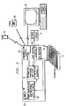
- FIG. 1 is a block diagram of a computer network having an EISA based computer system and a computer system manager constructed in accordance with the teachings of the present invention installed therein;
- FIG. 2 is a block diagram of the system manager of FIG. 1 which illustrates information flow to and from, as well as within, the system manager;
- FIG. 3 is a top level block diagram of the system manager of FIGS. 1-2.
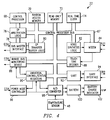
- FIG. 4 is a low level block diagram of the system manager of FIG. 3; and
- FIG. 5 is a flow diagram of the dataflow between the hardware and software components of the system manager of FIGS. 1-3.
- FIG. 6 is a schematic diagram of the innate bus monitoring device subject of the present invention; and
- FIG. 7 is a state diagram of the state machine controller of FIG. 6.
- Referring first to FIG. 1, an extended industry standard architecture (or "EISA") based
computer network 10 having asystem manager 22 constructed in accordance with the present invention shall now be described in detail. Thecomputer network 10, which may be configured as either a LAN, WAN, or other type of network configuration, includes an EISAserver 12, for example, a Systempro Model 486-840 manufactured by Compaq Computer Corp. of Houston, Texas, having an EISA based computer system board comprised of a series of computer subsystems (not shown) interconnected by a EISA based system bus. As the computer subsystems themselves are not specifically illustrated herein, the EISA computer system board and EISA system bus are, for ease of illustration, indicated as a unified element, EISA system board/bus 13, although all specific references to such element shall specifically indicate which portion of the unified element is being considered in such reference. - Installed on the EISA
computer system board 13 are a plurality of cards which include thesystem manager 22, which, as will be more fully described below, is comprised of a 32 bit intelligent bus master board and supporting firmware, an EISAnetwork interface adapter 24 and an intelligent diskarray controller device 26. Installed in the operating system (or "OS") section of the EISAserver 12 is anetwork operating system 14, preferably one which includes anetwork management agent 15. It is comtemplated that any one of numerous network operating systems, for example, the NetWare or LAN Manager network operating systems previously described, would be suitable for use as thenetwork operating system 14. - Interfacing the
system manager 22 and thenetwork operating system 14 is a systemmanager device driver 16. The systemmanager device driver 16 acts as a bi-directional translator for all requests to and from thesystem manager 22, thereby providing two-way communication between thesystem manager 22 and thenetwork management agent 15. Through this interconnection between thesystem manager 22 and thenetwork management agent 15, thenetwork management agent 15 may supply information to or receive information collected by thesystem manager 22. Object management by thesystem manager 22 may, therefore, be initiated by thenetwork management agent 15 if thenetwork management agent 15 issues instructions to create, delete, modify, reset, or clear objects stored in thesystem manager 22. - The system
manager device driver 16 will also handle certain in-band and out-of band alerts. If generated by thesystem manager 22, an in-band alert will be transmitted by the systemmanager device driver 16 to thenetwork operating system 14 which, under the control of thenetwork management agent 15, will direct the in-band alert to a localnetwork manager console 36 connected to thenetwork operating system 14 by in-band network bus 42. Out-of-band alerts generated by thenetwork operating system 14, on the other hand, will be transmitted by the systemmanager device driver 16 to thesystem manager 22 for transmission to a remotely locatedsystem manager facility 34 connected to thesystem manager 22 via anasynchronous link 40, for example, a telephone connection. Two-way communication between thesystem manager 22 and the remotely located system manager console is provided by a system facility device driver 38. While there are additional signals transmitted between thesystem manager 22 and thenetwork operating system 14 by the systemmanager device driver 16, these additional signals shall be discussed in greater detail later. - The
network management agent 15 also operates as a central collection point for network management information for the EISAserver 12 by acting as a link between thesystem manager 22, other cards installed on thecomputer system board 13, and the computer network itself. For example, in the embodiment of the invention illustrated in FIG. 1, an EISAnetwork interface adapter 24, for example, a Model NE3200 32-bit Ethernet adapter manufactured by Anthem Electonics, Inc., and an intelligent diskarray controller device 26, are also installed on thecomputer system board 13. Thenetwork operating system 14 connects thecomputer system board 13 and, via a networkinterface device driver 18 which operates in a manner similar to the systemmanager device driver 16, thenetwork interface adapter 24 for two-way data transmission therebetween. Furthermore, as thenetwork interface adapter 24 is connected for two-way data transmission with thenetwork 28, a two-way communication link between thesystem manager 22 and thenetwork 28 is thus provided. Thenetwork 28 is the interface of the netwwork components via the network media. Thenetwork 28 may be configured in a token ring, Ethernet, or other network topology in use today, to control the access of multiple computer stations to thenetwork 28, although, in the embodiment of the invention described and illustrated herein, asingle computer station 30 has been provided. - An intelligent disk array
controller device driver 20 which, like the networkinterface device driver 18, operates in a manner similar to the systemmanager device driver 16, provides for two-way data transmission between thesystem manager 22 and, via the network operating system, the intelligent diskarray controller device 26. The intelligent diskarray controller device 26 provides disk storage for thecomputer system board 13. For example, it is contemplated that the intelligent disk array (or "IDA")controller device 26 may provide 840 Mbytes of disk storage for thecomputer system board 13 by associating four 210M-byte Compaq IDA drive pairs therewith. - Referring next to FIG. 2, the flow of information, most commonly in the form of data and alerts, to and from, as well as within the
system manager 22 shall now be described in greater detail. As will be more fully described below, thesystem manager 22 has the ability to monitor various system components and parameters. If a component experiences a failure or exhibits characteristics that indicate it may experience a failure, thesystem manager 22 detects the failure or characteristic indicative of a potential failure and reports the failure or characteristic indicative of a potential failure as an alert in a manner such that corrective action can be taken. - As may be seen in FIG. 2, the path by which data accumulated during the monitoring of system components and parameters indicative of an actual or potential failure may be any one of four paths, depending on the particular type of actual or potential failure being monitored. Each system component being monitored may be referred to as an object having a number of attributes. As the components continue to be monitored, the value of the object's attributes may change, for example, by incrementing, decrementing, updating, resetting or modifying. When the attributes exceed their boundary or threshold value, an alert will be generated. In addition to alerts, the attributes of objects may be utilized to provide continuous real-time monitoring of the
computer system board 13 without interfering with normal system operations. - Addressing the specific signals being monitored by the
system bus manager 22, thecomputer system bus 13 supplies certain signals to abus monitor 44 which will help determine the state of thecomputer system board 13. These signals include interrupt request (or "IRQ") signals, data memory request (or "DRQ") signals and input/output (or "I/O") signals. In one embodiment of the invention, it is contemplated that the bus monitor 44 monitors the I/O signals although, in a further embodiment of the invention, it is contemplated that the bus monitor 44 monitors the supplied IRQ, DRQ and I/O signals. If the signals are active, then the corresponding system resources are being used. In this manner, these signals may be used to monitor the performance of thecomputer system board 13. Other signals supplied by thecomputer system bus 13, are utilized during object management to indicate alert conditions. For example, the absence of the refresh signal will generate an alert since the lack of refresh may cause thefile server 12 to fail. Similarly, an indication of a memory parity error will cause the generation of an alert. Also innately monitored by the bus monitor 44 are the printer port, so that thesystem manager 22 can report whether or not there is a printer error or is out of paper, the asynchronous serial port, so that the system manager can monitor and log ansynchronous activity such as overrun errors, parity errors, and framing errors for system board serial ports, system software, so that software errors can be identified, and keyboard events, so that keystrokes can be logged and the relationship between a system failure and keyboard inputs can be analyzed. Finally, the bus monitor 44 will detect the assertion of IOCHK, indicative of a catastrophic board failure, and board "times out", indicative of a violation of EISA standards. The bus monitor 44 transfers these signals to information processing andalert determination elements 52 where the monitored information is processed. As will be more fully described below, the information processing andalert determination elements 52 of thesystem manager 22 is comprised of a control processor and supporting logic which, by the application of object management techniques, is configured to determine whether the monitored information warrants the generation of an alert. - The
system manager 22 further provides for the monitoring of other signals for delivery to the information processing andalert determination elements 52 for potential generation of alerts. These other signals are supplied to the information processing andalert determination elements 52 by a path distinct from that previously discussed. To power thesystem manager 22, thecomputer system bus 13 provides ±5 Volt and ±12 Volt lines to a power-temperature monitor/power supply elements 50. The level of voltage supplied to thesystem manager 22 is converted into a digital signal by an analog-to-digital converter included in the power-temperature monitor/power supply elements 50 and the digital power level signal is provided to the information processing andalert determination elements 52. For example, if a drop in system power is detected, the information processing andalert determination elements 52 will generate an alert. If, however, a complete loss of power occurs, thesystem manager 22 will switch to battery power and the event reported, again as an alert, through one or both of its asynchronous modem and serial connections. Briefly, however, after loss of system power, the system manager will switch into reserve power to deliver alerts and, after completing alert delivery, to standby mode to conserve power. After reserve power is exhausted, the system manager then switches into dormant mode to keep its RAM memory valid for an extended period of time and, after the expiration of the extended period of time, cutting power off completely. - The
system manager 22 is further provided with atemperature sensor 48. The internal temperature of thesystem manager 22 is continuously monitored by thetemperature sensor 48 and the measured temperature transmitted to power-temperature monitor/power supply elements 50 where analog to digital conversion of the monitored temparature is performed. The digital temperature level is then transmitted to information processing andalert determination elements 52 for object management. If the information processing andalert determination elements 52 determine that the temperature has risen above a predetermined threshold, then an alert may be issued. - Finally, a
bus master interface 46 is used to transfer certain signals from thenetwork operating system 14 to the information processing andalert determination elements 52. Typically, the information provided by thebus master interface 46 differs from that passively supplied by the bus monitor 44 or the power-temperature monitor/power supply elements 50 in that information supplied via thebus master interface 46 are supplied as hard inputs. However, by interfacing withnetwork operating system 14, thesystem manager 22 can monitor network resources other than thecomputer system board 13 itself. For example, in a typical network management system, the intelligent diskarray controller device 26 would provide management information to thenetwork management agent 15 such as the number of read errors that have occurred. In turn, thenetwork management agent 15 can provide that information to thesystem manager 22 via thebus master interface 46. - The information passively monitored by the
bus monitor 44 and the power-temperature monitor portion of the power-temperature monitor/power supply elements 50 and supplied to the information processing andalert determination elements 52, as well as that information supplied to the information processing andalert determination elements 52 by thebus master interface 46 may be used for several purposes. First, the information processing andalert determination elements 52 can process the information and, if appropriate, generate an alert. Examples of alert conditions that may be determined by information processing andalert determination elements 52 include loss of system power, server subsystem failure, excessive server temperature as well as other configurable events that require outside attention. - Once the information processing and
alert determination elements 52 determine that an alert should be issued, such an alert can be issued in a number of ways. Initially, it must be determined if the alert should be delivered "in-band" or "out-of-band". Once originated by the information processing andalert determination elements 52, an in-band alert is directed to thebus master interface 46 and on to thenetwork operating system 14 and, under the control of the network management software contained in thenetwork management agent 15, on to the localnetwork manager console 36. So that the use of existing network hardware is maximized, it is contemplated that in-band alerts to the localnetwork manager console 36 will be utilized as the primary path for communications with thesystem manager 22. It should be specifically noted, however, that, a local system manager console may be used to receive in-band alerts without departing from the practice of the present invention. If the information processing andalert determination elements 52 determine that the alert should be issued "out-of-band", the alert is transmitted tocommunication elements 54 where an alert is issued. The communication elements may send an out-of-band alert by sending a protocol message over a switched telephone connection to thesystem manager facility 34, by dialling a phone number associated with apager 56 or by dialing a phone number to aphone 58 associated with a person and generating a synthesized voice message upon completing a connection with thephone 58. - In addition to alert determination and generation based upon the passively monitored information, the information processing and
alert determination elements 52 also perform several other functions. More specifically, the received information is also time stamped and stored or "logged" into RAM memory for later access. Thus, in the event of a catastrophic failure of thefile server 12, the monitored and logged information will be available for "post mortem" diagnostics. Similarly, network information may be transferred over thebus master interface 46 and logged into RAM memory contained within the information processing andalert determination elements 52. Finally, the objects can be transferred, for example to the remotesystem manager facility 34 or the localnetwork manager console 36 to provide real-time information regarding the performance of thesystem manager 22. - Through the link between the
communications elements 54 of thesystem manager 22 and thesystem manager facility 34, significant control of thesystem manager 22 can be performed from a remote location. From thesystem manager facility 34, remote console emulation, access to stored data and remote control or "rebooting" may be performed. Remote console emulation or "hard key insertion" permits keystrokes at the remote console to be delivered to thesystem manager 22 as if they were input locally. Through the hard key insertion, "soft" reboots are emulated by simultaneously inserting "control"--"alt"--"del" to actuate a reboot of thesystem manager 22. While not being able to actuate a complete "hard" reboot, thesystem manager facility 34 can simulate a hard reboot by selectively removing power from system components. - Referring next to FIG. 3, the structural configuration of the
system manager 22 shall now be described in greater detail. While quite similar to FIG. 2, certain elements of thesystem manager 22 have now been redesignated to more closely describe their structural configurations whereas, in FIG. 2, such elements were designated with their operational characteristics closer in mind. As may be better seen in Fig. 3, the bus monitor 44 innately monitors a plurality of signals relating to the state of thecomputer system board 13. Innate monitoring is accomplished by the bus monitor 44 receiving all data and address signals being transferred along thesystem bus 13. The bus monitor 44 will then select those signals which will help determine the state of thecomputer system board 13 and directs the selected signals via a bus to, what previously was functionally designated as the information processing andalert determination elements 52 and what is now structurally designated as a CPU/memory subsystem 52 which is the hardware which, together with associated firmware, will perform the aforementioned information processing and alert determination functions. Other signals, indicated here as miscellaneous system signals, are always considered to help determine the state of the computer system board and are directed through the bus monitor 44 to the CPU/memory subsystem 52. Additionally, thesystem bus 13 supplies power to thesystem manager 22 via ±5V, ±12V lines to the power-temperature monitor/power supply element 50 and on to the CPU/memory subsystem 52. In the event of that the supply of power from thesystem bus 13 is terminated, the power-temperature monitor/power supply element 50 will begin supplying power from a battery included therein. The termination of the supply of power from the system bus will also be reported to the CPU/memory subsystem 52 as an alert condition. - Connected to output of the CPU/memory subsystem is a modem/
asynchronous interface 60 represents the two paths along which an out-of-band alert may be transmitted, via an asynchronous communication port or via a modem, in the event that an alert condition has been established. Alert conditions include loss of system power, server subsystem failure, excessive server temperature as well as out of other events which require the attention of thesystem manager facility 34. Either of these may be used to report an alert condition, although the modem would typically contact either one of thepager 56 or thephone 58 while the asynchronous communication port would typically contact a remote system manager, for example thesystem manager facility 34 illustrated in FIG. 2. Servicing the modem/asynchronous interface 60 is voice/audio elements 62. In the event that a voice alert is selected, the voice audio elements generate the voice alert which is then transferred to aphone 58 via the modem. Finally, in the system manager configuration illustrated herein, a localsystem manager console 64 and system memory I/O support thesystem manager 22 and are accessible via thebus master interface 46. - Referring next to FIG. 4 the
system manager 22 shall now be described in still greater detail. Thesystem manager 22 is comprised of a bi-directionalcontrol processor bus 67 and a series manager components connected to thecontrol processor bus 67 for the transfer of address, data and control signals between various components of thesystem manager 22. Connected to thecontrol processor bus 67 are acontrol processor 68,random access memory 70, read onlymemory 72, areal time clock 74, controlprocessor arbitration logic 76, abus master interface 78, control processortransfer buffer logic 80,voice synthesis logic 82, amodem 84, a innatebus monitoring device 86, atouch tone decoder 88, universal control/status registers 90, a universal asynchronous receiver transmitter (or "UART") 92, aUART interface 94, apower mode controller 96, an analog-to-digital converter 98; and indirectly abattery 100 and abattery charge indicator 102 and atemperature sensor 48. - The various operations performed by the
system manager 22 and the varioussystem manager components 48 and 68-102 which are utilized to perform such operations shall now be described in greater detail. In the embodiment of the invention disclosed herein, thecontrol processor 68 is a 16 bit microprocessor which operates at 16 MHz, although, in alternate embodiments of the invention, other microprocessor types will be suitable for use. Thecontrol processor 68 performs multiple tasks, including a primary task of collecting and storing information received from multiple sources and detecting failures based upon acquired data and issue alerts as appropriate. Thecontrol processor 68 also performs several other tasks which will be described in greater detail later. In its primary task, object data which is processed by thecontrol processor 68 is stored in therandom access memory 70 and processor instructions are stored in the read onlymemory 72. Depending on the particular object management performed on a particular system component, data from thecomputer system bus 13 and innately monitored by the innatebus monitoring device 86 may be operated on by thecontrol processor 68 and the resultant object stored in therandom access memory 70 or, depending on the particular object being managed, may be directly stored into therandom access memory 70. Similarly, temperature and/or power data transmitted by the A/D converter 98 may be operated on by thecontrol processor 68 and the result stored in therandom access memory 70 or may be directly stored into therandom access memory 70. The real time clock is a clock independent of the system clock which is configured to store date, time, year and other time related variables relating to objects, depending on user preference. - In "normal" operation, the
control processor 68 controls thecontrol processor bus 67 to provide data transfers between thecontrol processor 68, therandom access memory 70, the read onlymemory 72 and thereal time clock 74. In normal operation, thecontrol processor 68 performs object management as set forth in detail elsewhere. Based upon the acquired data, object management will provide for the detection of failures of thefile server 12 or subsystems thereof. - The
bus master interface 78 which, for example, may be an Intel 82355 BMIC, is configured to interrogate and modify the memory and I/O space 66 of thecomputer system 13 as well as therandom access memory 70 of thesystem manager 22. For example, during a "data transfer operation" involving thesystem manager 22, the controlprocessor arbitration logic 76 instructs thecontrol processor bus 67 regarding the address, direction and destination of the data transfer. The controlprocessor arbitration logic 76 then instructs thebus master interface 78 as to the transfer. Once thesystem manager 22 is ready for a transfer, thebus master interface 78 will then instruct thecomputer system bus 13 to arrange for a burst transfer of data to thebus master interface 78 which, in turn, will transfer the data, to the control processortransfer buffer logic 80 and on to therandom access memory 70 for storage. Transfer of data from therandom access memory 70 to thebus master interface 78 is accomplished in reverse manner. - Once, object management within the
control processor 68 has indicated that an alert should be generated, thecontrol processor 68 controls the delivery of the appropriate alert message via themodem 84, theUART 94 and/or thenetwork operating system 15. TheUART 94 provides an asynchronous interface between thesystem manager 22 and thesystem manager facility 34. Through a software interface provided between theUART 94 and thesystem manager facility 34, for example, by use of the Windows software, thesystem manager facility 34 is capable of reading monitored object values from and writing object control to thesystem manager 22. Likewise, video screen data can be transmitted from thesystem manager 22 to the remote console and keystrokes can be transmitted from thesystem manager facility 34 to thesystem manager 22. Thesystem manager facility 34 also keeps alert logs. Finally, another function of theUART 94 is to connect an external modem to deliver page alerts under the control of thecontrol processor 68. - As previously mentioned, alerts delivered to the
pager 54 or thephone 56 are made via themodem 84 under the control of thecontrol processor 68. When, however, an alert message is delivered to thephone 56, thevoice synthesis logic 82 is utilized by thecontrol processor 68 in order to generate an audible, voice alert. Pre-recorded voice messages are stored within thevoice synthesis logic 82. These voice messages, which are stored in accordance with adaptive differential pulse code modulation, relate to a multitude of messages which may be accessed by the control processor and transmitted. For example, dates, numbers, alert conditions, names, voltages which correspond to the information useful to identify the type, severity, time of, location, or other identifying information regarding alert conditions. Thus, if the control processor desired to transmit a voice alert, thecontrol processor 68 would instruct thevoice synthesis logic 82 to supply the selected message to themodem 84, which, for example may be a 2400 bit per second modem, can transmit the selected message over its two way interface with thephone 58. After the alert has been transmitted, themodem 84 will await a return call through which it will pass server information and control. - The
touch tone decoder 88 is connected to accept analog signals from themodem 84. Thetouch tone decoder 88 decodes signals received by the modem and informs the control processor as to the nature of the signal. Most commonly, the touch tone decoder will be used to provide security for thesystem manager 22. For example, when a alert delivery is sent via themodem 84 to apager 56 or a phone, a user receiving the alert will, in many situations, desire to contact thesystem manager 22 for additional information. For example, if the user transmits a password to themodem 84, thetouch tone decoder 88 will decode the tones and transmit the decoded tones to thecontrol processor 68. Thecontrol processor 68 then decides whether the password is legitimate. Thetouch tone decoder 88 is also utilized in connection with remote console emulation operations. - The
power mode controller 92 both controls the power for thesystem manager 22 and monitors the power level for the system board. The power mode controller will control the operation of thesystem manager 22 by designating which of alternate power modes thesystem manager 22, or in accordance with the requirements of certain power modes, which components of thesystem manager 22 are to be supplied power. In the event that power from thesystem bus 13 is unavailable, thebattery 100 shall supply power to either thesystem manager 22 or to selected components thereof. As thebattery 100 is rechargeable, thebattery charge indicator 102 is provided to indicate when thebattery 100 is being recharged. For example, thepower mode controller 92 will cause thesystem manager 22 to activate thebattery 100 should the supply voltage needed to operate thesystem manager 22 fall below a minimum operating voltage. Thepower mode controller 92 will also turn on and off devices not needed during operation of thebattery 100. This circuitry will provide the best use of thebattery 100 in this low power mode. After the processor delivers an alert, thepower mode controller 92 will turn off the power to thecontrol processor 68. The processor will be restarted when a call is detected, UART activity, expiration of set interval in real time clock and other system activity or subsystem activity. - Referring next to FIG 5, the flow of data between the various hardware and firmware components of the
system manager 22 shall now be described in greater detail. System manager occurs within thecontrol processor 68 by the interaction of thecontrol processor firmware 104 with the control processor'srandom access memory 70 as well as certain other hardware elements. In a manner to be more fully described below, thesystem manager firmware 104 acts upon inputs from thebus master interface 78 and theUART 94, monitors parameters of thesystem board 13 being input by the innatebus monitoring device 86, monitors temperature and power parameters of thesystem board 13 being input by the A/D converter 98, and, as deemed necessary, generate alerts via thebus master interface 78 and/or theUART 94. - The
system manager 22 operates based upon the concept of object management. Each object represents a system component that can be managed and contains pertinent information about the component that it represents. As changes occur that affect the status of a component, the information contained in the corresponding object is updated. Objects and/or data related to objects are input to thesystem manager firmware 104, processed therein, and stored in anobject space 108 located within therandom access memory 70. Theobject space 108 is managed by anobject manager 106 which receives object messages from thebus master interface 78, theUART 94, and, in the case of innate objects updates, from within thesystem manager firmware 104 itself. - More specifically, an
EISA monitor 110, in conjunction with programmable hardware within the innatebus monitoring device 86, selectively listens to bus activity. As events are detected, the EISA monitor 110 provides information relating to the object manager for updating the innate objects corresponding to the event. Similarly, the voltage/temperature monitor 112 periodically monitors the ±5, ±12 voltages supplied to thesystem bus manager 22 by thesystem bus 13 and updates the innate objects corresponding to power and temperature. In the event of a loss of power from thesystem bus 13, however, the voltage/temperature monitor 112 will report a power event directly to acontrol manager 118. - For each update, increment or decrement, the
object manager 106 will, in the event that a boundary or threshold has been exceeded, determine that an alert needs to be issued. Theobject manager 106 will then request that an alert manager 114 compose an appropriate alert message and transmit the composed message. If the composed alert message is to be an in-band alert, the alert message is sent to a busmaster interface manager 116 and, if the composed alert message is to be an out-of-band alert, the alert message is sent to thecontrol manager 118. Thecontrol manager 118 would then forward the out-of-band alert to an asynchronous communication manager 120. The asynchronous communication manager 120 acts a traffic controller between the various tasks to be performed by thesystem manager firmware 104 and anasynchronous manager 122 which provides the firmware interface between thesystem firmware 104 and both themodem 84 and theUART 94. For example, if a voice message is to be generated for the out-of-band alert, the asynchronous communication manager 120 would interface with a voice/tone manager 124 which, like theasynchronous manager 122, provides the firmware interface between the system firmware and thevoice synthesis logic 82 and thetouch tone decoder 88. Thus, during the out-of-band alert delivery, the asynchronous communication manager 120 would transfer the alert message, as well as any voice message to accompany and/or comprise the alert, to theasynchronous manager 122 which would then deliver the alert message, either via themodem 84 or theUART 94. - Finally, in addition to delivering out-of-band alert messages originating with the alert manager 114 to the asynchronous communication manager 120, the
control manager 118 performs several other functions. First, in the event of critical event occurences, such as loss of power or failure to communicate with thesystem 13, the control manager will directly generate out-of-band alert messages. Second, the control manager servers to monitor significant events monitored by other managers, log events in anevent log 126 which, like theobject space 108, is located within therandom access memory 70, and provide logged information as requested. Logged information can be requested by the bus master interface manager for transfer, via the bus master interface to thenetwork operating system 14 and by the asynchronous communication manager 120 for transfer via theasynchronous manager 122 to theUART 94. - Referring next to FIG 6, the innate
bus monitoring device 86 subject of the present invention shall now be described in greater detail. At the start of a system bus cycle, the innate bus monitor'sstate machine controller 156 begins the process of reading in data on thesystem bus 13. Thus, in addition to being transferred to their original destinations to perform their designated functions, all address and data signals being transferred along thesystem bus 13 are input to a series ofaddress buffers 150 and a series ofdata buffers 152, respectfully. By pipelining the address and data signals input to the innatebus monitoring device 86 through a series of address anddata buffers data buffers system bus 13 to the innatebus monitoring device 86 are delayed a short time period. Preferably, the pipelining delay is sufficiently long so that the prior signals delivered to the innatebus monitoring device 86 may be processed. During high speed operations, signals would be delivered at a very high rate, most typically as a data burst with a transfer rate of up to 33 Mbytes/second. In view of the high rate of data transfer occuring on thesystem bus 13, pipelining the input address and data signals to delay output from the address anddata buffers data buffers - When a system bus cycle ends, a
state machine controller 156 determines if that cycle represents an event of interest to thatcontrol processor 68. Thus from the last of the series of address buffers 150, the address signals are then decoded in an addressvector decoder unit 154 which, for example, may be a 64K x 8 programmable read only memory (or "PROM") and which effectively acts as a pre-filter for the innatebus monitoring device 86. The address signals are input to the addressvector decoder unit 154 as 16 bit input addresses. The addressvector decoder unit 154 has a series of 8 bit vectors stored therein that correspond to events which, if they occur on thesystem bus 13, would be considered to be of interest. Typically, the addresses of interest are pre-programmed into the addressvector decoder unit 154 before installation into the innatebus monitoring system 86. If an address transferred to theaddress vector decoder 154 from the address buffers 150 corresponds to an address pre-programmed into the addressvector decoder unit 154 as being an address of interest, the input address would select the corresponding 8 bit address vector pre-programmed into theaddress vector decoder 154 to be output therefrom. Furthermore, as theaddress vector decoder 154 is installed in a socket on theinnate monitoring device 86, the selected addresses of interest can be easily modified, for example, if it was later determined that an event having an address not previously pre-selected was of interest or if thesystem bus 13 being monitored by theinnate monitoring device 86 was increased in size. Theinnate monitoring device 86 is, therefore, readily scalable to handle a larger amount of data. - Upon completing the pre-filtering of the address vectors by the
address vector decoder 154, thestate machine controller 156 enables the last one of the series ofdata buffers 152, thereby enabling the address vectors pre-filtered to be limited to those address vectors corresponding to addresses of system bus data transfers that: (1) actually occurred and (2) is of interest, i.e. was a pre-selected PROM address and the data stored in the last of the data buffers 152 are input thedata filter 160 and data/control filter 162, both of which, for example, may be comprised of a 64K x 1 static random access memory (or "SRAM"). It should be noted, however, that selected data signals output from the last one of the series ofdata buffers 152 are input into each of thedata filter 160 and the data/control filter 162 while all of the vectors output from theaddress vector decoder 154 are input to each of thedata filter 160 and the data/control filter 162. - Within the
data filter 160 and the data/control filter 162, address vectors and data signals which correspond to pre-determined patterns are matched with each other. The matching process within thedata filter 160 and the data/control filter 162 are, however, slightly different from each other. The data filter 160 directly matches the address vectors input from theaddress vector decoder 154 with data input from the data buffers 152 and, when a match is completed a signal is sent to thestate machine controller 156 which, in turn, enables a first-in, first-out (or "FIFO") memory to read in the address and data signals from theaddress vector decoder 154 and the data buffers 152. Pattern matching within the data/control filter 162 would differ somewhat. Of the address vectors selected by the address vector decoder, those address vectors for which every data bit corresponding to the address vector is of interest are sent to thedata filter 160. The address vectors and system data are sent to the data filter, while the data/control filter receives address vectors, data, I/O, and masking control bits. To further increase the flexibility of theinnate monitoring device 86 to match address and data bits corresponding to events of interest, a mask input is provided to the data/control filter 162 to provide for dynamic modification of the combination of the supplied data signals which would be patterned by the data/control filter as corresponding to a selected address vector of interest. - Data corresponding to each address vector output by the
address vector decoder 154 are selected and written, together with the corresponding address vector to either theFIFO memory 158 or to registerfiles FIFO memory 158. When address and data information relating to an event of interest is stored in theFIFO memory 158, an interrupt signal will be transmitted to thesystem manager 22. Thesystem manager 22 can, in turn, either read the information at that time or read the information stored at a later time. - The
FIFO memory 158 may be chosen of any size, depending on certain characteristics of the system being monitored. For example, in the embodiment of the invention disclosed herein, a FIFO memory sized to store 512 x 16 bits of memory is contemplated. A FIFO memory of this size would enable data relating to approximately 500 events of interest to be stored in theFIFO memory 158 before events would be missed. This would reduce the need for thecontrol processor 68 to repeatedly remove information stored in theFIFO memory 158. - Certain other signals relating to events of interest are related directly from the
system bus 13 to the control processor. These signals relate to events which are always considered to be of interest to thesystem manager 22 and for which the control processor should be immediately interrupted upon occurence. IRQ and DRQ signals, both of which have been previously described at length, are delivered immediately from thesystem bus 13 to an miscellaneousEISA signal monitor 168. In addition, signals related to the updating of the video screen of theremote console 34 are delivered to avideo memory monitor 170 which, in turn, issues a signal to the miscellaneous EISA signal monitor whenever the video screen is updated. The miscellaneous EISA monitor 168 would then issue an interrupt request to thecontrol processor 67 for delivery of the event to thecontrol processor 68. - Referring next to FIG. 7, the operation of the
state machine 156 shall now be described in greater detail. An idle or "0" state for thestate machine controller 156 occurs atbubble 172. When theinnate monitoring device 86 is enabled by enabling the address anddata buffers state machine controller 156 entersstate 1 atbubble 174. Thestate machine controller 156 will stay instate 1 until the system bus cycle ends, where thestate machine 156 will enterstate 3 atbubble 176.State 3 is a decision state in that thestate machine controller 156 will decide whether to read address and data signals into theFIFO memory 158, anindex register file 164 or adata register file 166 and selection shall be made based upon the contents of certain bits of the address data vector to be read which provide information regarding how dynamic the selected data is. If, based upon certain of the vector bits, the data is considered to be sufficiently dynamic to require storage in the register files 164, 166, thestate machine controller 156 will state 5 atbubble 182, proceed tostate 4 atbubble 180 to conduct a write to theindex register file 164, followed by a second loop throughstates 0 atbubble bubble bubble bubble bubble 180 to complete a write to thedata register file 166. - Returning to the
decision state 3 atbubble 176, if it is determined that, based upon certain of the vector bits, the data is not sufficiently dynamic to require storage in the register file, thestate machine controller 156 will proceed tostate 2 atbubble 178 where a FIFO write is selected and on tostate 4 atbubble 180 where the FIFO write is performed. - Thus, there has been described and illustrated herein, an innate bus monitoring device which passively monitors signals being transferred on the system bus for a computer system and selects certain ones of those signals as being related to the condition of the system and delivering the selected signals to a computer processor for object management. By passively monitoring all signals and then delivering only those signals of interest, a significant reduction in processing time is achieved. Furthermore, the number of interrupts to the computer processor which must be generated during the monitoring process is reduced. However, those skilled in the art will recognize that many modifications and variations besides those specifically mentioned may be made in the techniques described herein without departing substantially from the concept of the present invention. Accordingly, it should be clearly understood that the form of the invention as described herein is exemplary only and is not intended as a limitation on the scope of the invention.
Claims (8)
- A monitoring system (86) for monitoring a computer system including a system bus (13), the monitoring system: comprising:means (150,152) for receiving all address and data signals transferred over said system bus;means (154) for selecting address signals related to operating conditions of said computer system by selecting address signals which match preselected address signals;means (156) for classifying selected data signals related to operating conditions of said computer system as either in a first class or a second class based upon said selected address signals;a data filter (160) for selecting data signals which correspond to said selected address signals;first storage (166) means for storing said selected address and data signals related to operating conditions of said computer system and classified in said first class;second storage means (158,164) for storing said selected address and data signals related to operating conditions of said computer system and classified in said second class; andmeans (156) for selectively directing said signals to said first storage means or said second storage means based upon said classification of said data signals as either in said first class or said second class.
- A monitoring system (86) according to claim 1, wherein said first storage means (166) further comprises:a register file (166) for storing said address and data signals classified in said first class; and said second storage means (158,164) further comprises:a first-in, first-out memory (158) for storing said address and data signals classified in said second class.
- A monitoring system (86) according to claim 2, and further comprising:an address (150) buffer for receiving all of said address signals transferred over said system bus; anda data buffer (152) for receiving all of said data signals transferred over said system bus.
- A monitoring system (86) according to claim 3, wherein said means (54) for selecting address signals related to operating conditions of said computer system further comprises an address prefilter (154) having a series of address vectors stored therein, said address prefilter (154) comparing said address signals transferred over said system bus (13) to said address vectors and propagating said address vectors which match said address signals to said data filter (160), said data filter receiving said received data signals from said data buffer (152) and identifying said received data signals which correspond to said propagated address vectors.
- A monitoring system (86) according to claim 4 and further comprising a state machine (154) connected to said data filter (160), said state machine receiving selected bits of received data signals relating to operating conditions and having control outputs connected to said register file (164) and said first-in, first-out memory (158), respectively, said state machine controlling the selective propagation of said received data signals related to operating conditions to either said register file or said first-in, first-out memory based upon the contents of said selected bits of said received data signals.
- A monitoring system (86) according to claim 2, wherein said means (156) for classifying selected data signals related to operating conditions of said computer system as either in said first or second classes further comprises means for classifying said selected data signals related to operating conditions of said computer system as either in said first or second classes based upon the contents of selected bits of said selected address signals.
- A computer network (10) comprising:a file server (12) having a system board with a system bus (13) installed therein;at least one computer station;a network connecting said at least one computer station to said file server;a network operating system (14) for controlling information transfers between said file server (12) and said at least one computer station via said network, said network operating system including a network manager for managing information transfers along said network; anda system manager (22) including a monitoring system (86) according to any of the preceding claims.
- A computer system comprising:a file server having a system board (13) with a system bus (13) installed therein;a system manager (22) for managing said system board, said system manager managing said system board by monitoring signals transferred along said system bus of said system board said system manager including a computer processor (68) and monitoring system (86) according to any of claims 1 to 6.
Applications Claiming Priority (2)
| Application Number | Priority Date | Filing Date | Title |
|---|---|---|---|
| US71924091A | 1991-06-24 | 1991-06-24 | |
| US719240 | 1991-06-24 |
Publications (3)
| Publication Number | Publication Date |
|---|---|
| EP0520766A2 EP0520766A2 (en) | 1992-12-30 |
| EP0520766A3 EP0520766A3 (en) | 1993-10-27 |
| EP0520766B1 true EP0520766B1 (en) | 1997-11-12 |
Family
ID=24889319
Family Applications (1)
| Application Number | Title | Priority Date | Filing Date |
|---|---|---|---|
| EP92305798A Expired - Lifetime EP0520766B1 (en) | 1991-06-24 | 1992-06-24 | Innate bus monitor for computer system manager |
Country Status (5)
| Country | Link |
|---|---|
| US (1) | US5402431A (en) |
| EP (1) | EP0520766B1 (en) |
| AT (1) | ATE160234T1 (en) |
| CA (1) | CA2072178A1 (en) |
| DE (1) | DE69223090T2 (en) |
Families Citing this family (83)
| Publication number | Priority date | Publication date | Assignee | Title |
|---|---|---|---|---|
| DE69516199T2 (en) * | 1994-02-23 | 2000-09-21 | Sun Microsystems, Inc. | Method and arrangement for power saving in a computer system using a power control pseudo device driver |
| US5630058A (en) * | 1994-10-13 | 1997-05-13 | International Business Machines Corporation | Network connected device protection |
| US5664093A (en) * | 1994-12-27 | 1997-09-02 | General Electric Company | System and method for managing faults in a distributed system |
| JPH08286989A (en) * | 1995-04-19 | 1996-11-01 | Fuji Xerox Co Ltd | Network management system |
| US5732215A (en) * | 1995-06-07 | 1998-03-24 | International Business Machines Corporation | System for equalizing operating temperature by allocating infrequently accessed data to the high temperature DASD and allocating frequently accessed data to the low temperature DASD |
| US5974573A (en) * | 1996-01-16 | 1999-10-26 | Dell Usa, L.P. | Method for collecting ECC event-related information during SMM operations |
| US5644707A (en) * | 1996-02-16 | 1997-07-01 | Chen; Tian-Luh | Computer mainframe signal monitoring system |
| US5696701A (en) * | 1996-07-12 | 1997-12-09 | Electronic Data Systems Corporation | Method and system for monitoring the performance of computers in computer networks using modular extensions |
| US5796633A (en) * | 1996-07-12 | 1998-08-18 | Electronic Data Systems Corporation | Method and system for performance monitoring in computer networks |
| US5852720A (en) | 1996-08-16 | 1998-12-22 | Compaq Computer Corp. | System for storing display data during first time period prior to failure of computer and during second time period after reset of the computer |
| US6233634B1 (en) | 1996-08-17 | 2001-05-15 | Compaq Computer Corporation | Server controller configured to snoop and receive a duplicative copy of display data presented to a video controller |
| US6070253A (en) * | 1996-12-31 | 2000-05-30 | Compaq Computer Corporation | Computer diagnostic board that provides system monitoring and permits remote terminal access |
| US6418492B1 (en) | 1997-05-13 | 2002-07-09 | Micron Electronics | Method for computer implemented hot-swap and hot-add |
| US6173346B1 (en) | 1997-05-13 | 2001-01-09 | Micron Electronics, Inc. | Method for hot swapping a programmable storage adapter using a programmable processor for selectively enabling or disabling power to adapter slot in response to respective request signals |
| US6247080B1 (en) | 1997-05-13 | 2001-06-12 | Micron Electronics, Inc. | Method for the hot add of devices |
| US6499073B1 (en) | 1997-05-13 | 2002-12-24 | Micron Electronics, Inc. | System using programmable processor for selectively enabling or disabling power to adapter in response to respective request signals |
| US6073255A (en) * | 1997-05-13 | 2000-06-06 | Micron Electronics, Inc. | Method of reading system log |
| US6249828B1 (en) | 1997-05-13 | 2001-06-19 | Micron Electronics, Inc. | Method for the hot swap of a mass storage adapter on a system including a statically loaded adapter driver |
| US6202160B1 (en) | 1997-05-13 | 2001-03-13 | Micron Electronics, Inc. | System for independent powering of a computer system |
| US6247079B1 (en) * | 1997-05-13 | 2001-06-12 | Micron Electronics, Inc | Apparatus for computer implemented hot-swap and hot-add |
| US6134673A (en) * | 1997-05-13 | 2000-10-17 | Micron Electronics, Inc. | Method for clustering software applications |
| US6253334B1 (en) | 1997-05-13 | 2001-06-26 | Micron Electronics, Inc. | Three bus server architecture with a legacy PCI bus and mirrored I/O PCI buses |
| US6330690B1 (en) | 1997-05-13 | 2001-12-11 | Micron Electronics, Inc. | Method of resetting a server |
| US6182180B1 (en) | 1997-05-13 | 2001-01-30 | Micron Electronics, Inc. | Apparatus for interfacing buses |
| US6195717B1 (en) | 1997-05-13 | 2001-02-27 | Micron Electronics, Inc. | Method of expanding bus loading capacity |
| US6324608B1 (en) * | 1997-05-13 | 2001-11-27 | Micron Electronics | Method for hot swapping of network components |
| US6269417B1 (en) | 1997-05-13 | 2001-07-31 | Micron Technology, Inc. | Method for determining and displaying the physical slot number of an expansion bus device |
| US5987554A (en) * | 1997-05-13 | 1999-11-16 | Micron Electronics, Inc. | Method of controlling the transfer of information across an interface between two buses |
| US6363497B1 (en) | 1997-05-13 | 2002-03-26 | Micron Technology, Inc. | System for clustering software applications |
| US6219734B1 (en) | 1997-05-13 | 2001-04-17 | Micron Electronics, Inc. | Method for the hot add of a mass storage adapter on a system including a statically loaded adapter driver |
| US6179486B1 (en) | 1997-05-13 | 2001-01-30 | Micron Electronics, Inc. | Method for hot add of a mass storage adapter on a system including a dynamically loaded adapter driver |
| US6145098A (en) | 1997-05-13 | 2000-11-07 | Micron Electronics, Inc. | System for displaying system status |
| US6192434B1 (en) | 1997-05-13 | 2001-02-20 | Micron Electronics, Inc | System for hot swapping a programmable adapter by using a programmable processor to selectively disabling and enabling power thereto upon receiving respective control signals |
| US6282673B1 (en) * | 1997-05-13 | 2001-08-28 | Micron Technology, Inc. | Method of recording information system events |
| US6338150B1 (en) * | 1997-05-13 | 2002-01-08 | Micron Technology, Inc. | Diagnostic and managing distributed processor system |
| US6163849A (en) * | 1997-05-13 | 2000-12-19 | Micron Electronics, Inc. | Method of powering up or powering down a server to a maintenance state |
| US6269412B1 (en) * | 1997-05-13 | 2001-07-31 | Micron Technology, Inc. | Apparatus for recording information system events |
| US6292905B1 (en) | 1997-05-13 | 2001-09-18 | Micron Technology, Inc. | Method for providing a fault tolerant network using distributed server processes to remap clustered network resources to other servers during server failure |
| US6138250A (en) * | 1997-05-13 | 2000-10-24 | Micron Electronics, Inc. | System for reading system log |
| US6249885B1 (en) | 1997-05-13 | 2001-06-19 | Karl S. Johnson | Method for managing environmental conditions of a distributed processor system |
| US6266721B1 (en) | 1997-05-13 | 2001-07-24 | Micron Electronics, Inc. | System architecture for remote access and control of environmental management |
| US6122758A (en) * | 1997-05-13 | 2000-09-19 | Micron Electronics, Inc. | System for mapping environmental resources to memory for program access |
| US6202111B1 (en) | 1997-05-13 | 2001-03-13 | Micron Electronics, Inc. | Method for the hot add of a network adapter on a system including a statically loaded adapter driver |
| US6134668A (en) * | 1997-05-13 | 2000-10-17 | Micron Electronics, Inc. | Method of selective independent powering of portion of computer system through remote interface from remote interface power supply |
| US6170067B1 (en) | 1997-05-13 | 2001-01-02 | Micron Technology, Inc. | System for automatically reporting a system failure in a server |
| US6243773B1 (en) | 1997-05-13 | 2001-06-05 | Micron Electronics, Inc. | Configuration management system for hot adding and hot replacing devices |
| US6304929B1 (en) | 1997-05-13 | 2001-10-16 | Micron Electronics, Inc. | Method for hot swapping a programmable adapter by using a programmable processor to selectively disabling and enabling power thereto upon receiving respective control signals |
| US6170028B1 (en) | 1997-05-13 | 2001-01-02 | Micron Electronics, Inc. | Method for hot swapping a programmable network adapter by using a programmable processor to selectively disabling and enabling power thereto upon receiving respective control signals |
| US6163853A (en) | 1997-05-13 | 2000-12-19 | Micron Electronics, Inc. | Method for communicating a software-generated pulse waveform between two servers in a network |
| US6249834B1 (en) | 1997-05-13 | 2001-06-19 | Micron Technology, Inc. | System for expanding PCI bus loading capacity |
| US6243838B1 (en) | 1997-05-13 | 2001-06-05 | Micron Electronics, Inc. | Method for automatically reporting a system failure in a server |
| US6199173B1 (en) | 1997-10-01 | 2001-03-06 | Micron Electronics, Inc. | Method for mapping environmental resources to memory for program access |
| US6154835A (en) * | 1997-10-01 | 2000-11-28 | Micron Electronics, Inc. | Method for automatically configuring and formatting a computer system and installing software |
| US6212585B1 (en) | 1997-10-01 | 2001-04-03 | Micron Electronics, Inc. | Method of automatically configuring a server after hot add of a device |
| US6065053A (en) * | 1997-10-01 | 2000-05-16 | Micron Electronics, Inc. | System for resetting a server |
| US6088816A (en) * | 1997-10-01 | 2000-07-11 | Micron Electronics, Inc. | Method of displaying system status |
| US6138179A (en) * | 1997-10-01 | 2000-10-24 | Micron Electronics, Inc. | System for automatically partitioning and formatting a primary hard disk for installing software in which selection of extended partition size is not related to size of hard disk |
| US6263387B1 (en) | 1997-10-01 | 2001-07-17 | Micron Electronics, Inc. | System for automatically configuring a server after hot add of a device |
| US6145102A (en) * | 1998-01-20 | 2000-11-07 | Compaq Computer Corporation | Transmission of an error message over a network by a computer which fails a self-test |
| US6687865B1 (en) | 1998-03-25 | 2004-02-03 | On-Chip Technologies, Inc. | On-chip service processor for test and debug of integrated circuits |
| GB2337139A (en) | 1998-05-09 | 1999-11-10 | Ibm | A bi-directional transaction intercepting filter and log |
| US6205503B1 (en) | 1998-07-17 | 2001-03-20 | Mallikarjunan Mahalingam | Method for the hot swap and add of input/output platforms and devices |
| US6223234B1 (en) | 1998-07-17 | 2001-04-24 | Micron Electronics, Inc. | Apparatus for the hot swap and add of input/output platforms and devices |
| US6308289B1 (en) * | 1998-10-01 | 2001-10-23 | International Business Machines Corporation | Method and system for environmental sensing and control within a computer system |
| US6321287B1 (en) | 1998-10-19 | 2001-11-20 | Dell Usa, L.P. | Console redirection for a computer system |
| US6195768B1 (en) | 1998-12-16 | 2001-02-27 | Samuel I. Green | System and method for monitoring high speed data bus |
| US6408334B1 (en) | 1999-01-13 | 2002-06-18 | Dell Usa, L.P. | Communications system for multiple computer system management circuits |
| US6732067B1 (en) * | 1999-05-12 | 2004-05-04 | Unisys Corporation | System and adapter card for remote console emulation |
| US20020099886A1 (en) * | 1999-05-17 | 2002-07-25 | Emerson Theodore F. | System and method for controlling remote console functionality assist logic |
| US6636929B1 (en) | 2000-04-06 | 2003-10-21 | Hewlett-Packard Development Company, L.P. | USB virtual devices |
| US6691295B2 (en) * | 2001-09-25 | 2004-02-10 | Sun Microsystems, Inc. | Managing one or more domains in a system over a network connection |
| US7565424B2 (en) * | 2001-10-16 | 2009-07-21 | International Business Machines Corporation | Data processing system, method, and product for reporting loss of service application |
| US7051131B1 (en) * | 2002-12-27 | 2006-05-23 | Unisys Corporation | Method and apparatus for recording and monitoring bus activity in a multi-processor environment |
| US20060039464A1 (en) * | 2004-08-23 | 2006-02-23 | Emerson Theodore F | Method and apparatus for capturing video data to a virtual screen buffer |
| US7490023B2 (en) * | 2007-04-12 | 2009-02-10 | International Business Machines Corporation | Method for analyzing effects of performance characteristics of an application based on complex configuration models |
| WO2009033967A1 (en) * | 2007-09-13 | 2009-03-19 | Thomson Licensing | System and method for monitoring hard disk performance via a control path |
| US8410994B1 (en) | 2010-08-23 | 2013-04-02 | Matrox Graphics Inc. | System and method for remote graphics display |
| US20130064521A1 (en) * | 2011-09-09 | 2013-03-14 | Deepak Gonsalves | Session recording with event replay in virtual mobile management |
| CN103856364A (en) * | 2012-12-04 | 2014-06-11 | 鸿富锦精密工业(深圳)有限公司 | Bus signal monitoring device and method |
| GB2541454B (en) * | 2015-08-21 | 2021-10-13 | Siemens Ind Software Inc | Tracing interconnect circuitry |
| US12360851B2 (en) | 2023-10-31 | 2025-07-15 | Dell Products L.P. | Managing data backup for data processing systems using out-of-band methods |
| US12461823B2 (en) | 2023-10-31 | 2025-11-04 | Dell Products L.P. | Data recovery using out-of-band communications |
| US12306708B2 (en) * | 2023-10-31 | 2025-05-20 | Dell Products L.P. | Managing unrecoverable errors for data processing systems using out of band communication channels |
Family Cites Families (15)
| Publication number | Priority date | Publication date | Assignee | Title |
|---|---|---|---|---|
| US3670309A (en) * | 1969-12-23 | 1972-06-13 | Ibm | Storage control system |
| US4257095A (en) * | 1978-06-30 | 1981-03-17 | Intel Corporation | System bus arbitration, circuitry and methodology |
| FR2497373B1 (en) * | 1980-12-30 | 1986-09-05 | Bull Sa | MICROPROGRAMMABLE POWER SUPPLY SYSTEM FOR A DATA PROCESSING SYSTEM HAVING A SERVICE PANEL FOR MAINTENANCE OPERATIONS AND METHODS OF OPERATING THIS SERVICE PANEL |
| US4521849A (en) * | 1981-10-01 | 1985-06-04 | Honeywell Information Systems Inc. | Programmable hit matrices used in a hardware monitoring interface unit |
| GB8305011D0 (en) * | 1983-02-23 | 1983-03-30 | Microwriter Ltd | Computer apparatus and remote keyboards |
| JPS61107417A (en) * | 1984-10-30 | 1986-05-26 | Toshiba Corp | Keyboard control system |
| US4686526A (en) * | 1985-09-12 | 1987-08-11 | The United States Of America As Represented By The United States Department Of Energy | Remote reset circuit |
| US4780821A (en) * | 1986-07-29 | 1988-10-25 | International Business Machines Corp. | Method for multiple programs management within a network having a server computer and a plurality of remote computers |
| US4916441A (en) * | 1988-09-19 | 1990-04-10 | Clinicom Incorporated | Portable handheld terminal |
| US5099420A (en) * | 1989-01-10 | 1992-03-24 | Bull Hn Information Systems Inc. | Method and apparatus for limiting the utilization of an asynchronous bus with distributed controlled access |
| US5018060A (en) * | 1989-01-26 | 1991-05-21 | Ibm Corporation | Allocating data storage space of peripheral data storage devices using implied allocation based on user parameters |
| US5036455A (en) * | 1989-07-25 | 1991-07-30 | Tandem Computers Incorporated | Multiple power supply sensor for protecting shared processor buses |
| US5163151A (en) * | 1990-03-22 | 1992-11-10 | Square D Company | System for processing and prioritizing alarms from devices on data communications network |
| US5198805A (en) * | 1990-09-04 | 1993-03-30 | Hewlett-Packard Company | Method and apparatus for monitoring a network and locating a node using signal strength calculations |
| US5283792A (en) * | 1990-10-19 | 1994-02-01 | Benchmarq Microelectronics, Inc. | Power up/power down controller and power fail detector for processor |
-
1992
- 1992-06-23 CA CA002072178A patent/CA2072178A1/en not_active Abandoned
- 1992-06-24 EP EP92305798A patent/EP0520766B1/en not_active Expired - Lifetime
- 1992-06-24 AT AT92305798T patent/ATE160234T1/en not_active IP Right Cessation
- 1992-06-24 DE DE69223090T patent/DE69223090T2/en not_active Expired - Fee Related
-
1993
- 1993-11-23 US US08/157,335 patent/US5402431A/en not_active Expired - Lifetime
Also Published As
| Publication number | Publication date |
|---|---|
| CA2072178A1 (en) | 1992-12-25 |
| EP0520766A3 (en) | 1993-10-27 |
| US5402431A (en) | 1995-03-28 |
| DE69223090D1 (en) | 1997-12-18 |
| ATE160234T1 (en) | 1997-11-15 |
| EP0520766A2 (en) | 1992-12-30 |
| DE69223090T2 (en) | 1998-05-07 |
Similar Documents
| Publication | Publication Date | Title |
|---|---|---|
| US5402431A (en) | Innate bus monitoring system for computer system manager | |
| US5367670A (en) | Computer system manager for monitoring events and operating parameters and generating alerts | |
| US5283905A (en) | Power supply for computer system manager | |
| US5309563A (en) | Computer implemented method for transferring command messages between a system manager for a computer system and a network operating system associated therewith | |
| US6243838B1 (en) | Method for automatically reporting a system failure in a server | |
| US6170067B1 (en) | System for automatically reporting a system failure in a server | |
| US5272382A (en) | Power supply for computer system manager | |
| US5991806A (en) | Dynamic system control via messaging in a network management system | |
| US6067628A (en) | Method to monitor universal serial bus hub overcurrent | |
| US6341322B1 (en) | Method for interfacing two buses | |
| US5471617A (en) | Computer management system and associated management information base | |
| US6697963B1 (en) | Method of updating a system environmental setting | |
| US5835765A (en) | Computer operation management system for a computer operating system capable of simultaneously executing plural application programs | |
| US6065053A (en) | System for resetting a server | |
| US5559958A (en) | Graphical user interface for computer management system and an associated management information base | |
| US6330690B1 (en) | Method of resetting a server | |
| US6895285B2 (en) | Computer system status monitoring | |
| US5655083A (en) | Programmable rset system and method for computer network | |
| KR950001419B1 (en) | Logical event notification method and apparatus on a network | |
| US6122758A (en) | System for mapping environmental resources to memory for program access | |
| US20130073110A1 (en) | Diagnostic and managing distributed processor system | |
| KR0136501B1 (en) | Control Method of Signal Relay Switch Operation Management System | |
| US5463752A (en) | Method and system for enhancing the efficiency of communication between multiple direct access storage devices and a storage system controller | |
| JP3363707B2 (en) | Method of transmitting message from system administrator to peripheral device, network interface device, method of operating message transmission from printer, and printer | |
| KR0182632B1 (en) | Client server system performing automatic reconnection and control method thereof |
Legal Events
| Date | Code | Title | Description |
|---|---|---|---|
| PUAI | Public reference made under article 153(3) epc to a published international application that has entered the european phase |
Free format text: ORIGINAL CODE: 0009012 |
|
| AK | Designated contracting states |
Kind code of ref document: A2 Designated state(s): AT BE CH DE DK ES FR GB GR IT LI NL SE |
|
| PUAL | Search report despatched |
Free format text: ORIGINAL CODE: 0009013 |
|
| AK | Designated contracting states |
Kind code of ref document: A3 Designated state(s): AT BE CH DE DK ES FR GB GR IT LI NL SE |
|
| 17P | Request for examination filed |
Effective date: 19940419 |
|
| 17Q | First examination report despatched |
Effective date: 19960212 |
|
| GRAG | Despatch of communication of intention to grant |
Free format text: ORIGINAL CODE: EPIDOS AGRA |
|
| GRAH | Despatch of communication of intention to grant a patent |
Free format text: ORIGINAL CODE: EPIDOS IGRA |
|
| GRAH | Despatch of communication of intention to grant a patent |
Free format text: ORIGINAL CODE: EPIDOS IGRA |
|
| GRAA | (expected) grant |
Free format text: ORIGINAL CODE: 0009210 |
|
| AK | Designated contracting states |
Kind code of ref document: B1 Designated state(s): AT BE CH DE DK ES FR GB GR IT LI NL SE |
|
| PG25 | Lapsed in a contracting state [announced via postgrant information from national office to epo] |
Ref country code: NL Free format text: LAPSE BECAUSE OF FAILURE TO SUBMIT A TRANSLATION OF THE DESCRIPTION OR TO PAY THE FEE WITHIN THE PRESCRIBED TIME-LIMIT Effective date: 19971112 Ref country code: LI Free format text: LAPSE BECAUSE OF FAILURE TO SUBMIT A TRANSLATION OF THE DESCRIPTION OR TO PAY THE FEE WITHIN THE PRESCRIBED TIME-LIMIT Effective date: 19971112 Ref country code: IT Free format text: LAPSE BECAUSE OF FAILURE TO SUBMIT A TRANSLATION OF THE DESCRIPTION OR TO PAY THE FEE WITHIN THE PRESCRIBED TIME-LIMIT;WARNING: LAPSES OF ITALIAN PATENTS WITH EFFECTIVE DATE BEFORE 2007 MAY HAVE OCCURRED AT ANY TIME BEFORE 2007. THE CORRECT EFFECTIVE DATE MAY BE DIFFERENT FROM THE ONE RECORDED. Effective date: 19971112 Ref country code: GR Free format text: LAPSE BECAUSE OF FAILURE TO SUBMIT A TRANSLATION OF THE DESCRIPTION OR TO PAY THE FEE WITHIN THE PRESCRIBED TIME-LIMIT Effective date: 19971112 Ref country code: ES Free format text: THE PATENT HAS BEEN ANNULLED BY A DECISION OF A NATIONAL AUTHORITY Effective date: 19971112 Ref country code: DK Free format text: LAPSE BECAUSE OF NON-PAYMENT OF DUE FEES Effective date: 19971112 Ref country code: CH Free format text: LAPSE BECAUSE OF FAILURE TO SUBMIT A TRANSLATION OF THE DESCRIPTION OR TO PAY THE FEE WITHIN THE PRESCRIBED TIME-LIMIT Effective date: 19971112 Ref country code: BE Free format text: LAPSE BECAUSE OF FAILURE TO SUBMIT A TRANSLATION OF THE DESCRIPTION OR TO PAY THE FEE WITHIN THE PRESCRIBED TIME-LIMIT Effective date: 19971112 Ref country code: AT Free format text: LAPSE BECAUSE OF FAILURE TO SUBMIT A TRANSLATION OF THE DESCRIPTION OR TO PAY THE FEE WITHIN THE PRESCRIBED TIME-LIMIT Effective date: 19971112 |
|
| REF | Corresponds to: |
Ref document number: 160234 Country of ref document: AT Date of ref document: 19971115 Kind code of ref document: T |
|
| REG | Reference to a national code |
Ref country code: CH Ref legal event code: EP |
|
| REF | Corresponds to: |
Ref document number: 69223090 Country of ref document: DE Date of ref document: 19971218 |
|
| PG25 | Lapsed in a contracting state [announced via postgrant information from national office to epo] |
Ref country code: SE Free format text: LAPSE BECAUSE OF FAILURE TO SUBMIT A TRANSLATION OF THE DESCRIPTION OR TO PAY THE FEE WITHIN THE PRESCRIBED TIME-LIMIT Effective date: 19980212 |
|
| ET | Fr: translation filed | ||
| NLV1 | Nl: lapsed or annulled due to failure to fulfill the requirements of art. 29p and 29m of the patents act | ||
| REG | Reference to a national code |
Ref country code: CH Ref legal event code: PL |
|
| PLBE | No opposition filed within time limit |
Free format text: ORIGINAL CODE: 0009261 |
|
| STAA | Information on the status of an ep patent application or granted ep patent |
Free format text: STATUS: NO OPPOSITION FILED WITHIN TIME LIMIT |
|
| 26N | No opposition filed | ||
| REG | Reference to a national code |
Ref country code: GB Ref legal event code: IF02 |
|
| PGFP | Annual fee paid to national office [announced via postgrant information from national office to epo] |
Ref country code: DE Payment date: 20070731 Year of fee payment: 16 |
|
| PGFP | Annual fee paid to national office [announced via postgrant information from national office to epo] |
Ref country code: GB Payment date: 20070628 Year of fee payment: 16 |
|
| PGFP | Annual fee paid to national office [announced via postgrant information from national office to epo] |
Ref country code: FR Payment date: 20070618 Year of fee payment: 16 |
|
| GBPC | Gb: european patent ceased through non-payment of renewal fee |
Effective date: 20080624 |
|
| REG | Reference to a national code |
Ref country code: FR Ref legal event code: ST Effective date: 20090228 |
|
| PG25 | Lapsed in a contracting state [announced via postgrant information from national office to epo] |
Ref country code: DE Free format text: LAPSE BECAUSE OF NON-PAYMENT OF DUE FEES Effective date: 20090101 |
|
| PG25 | Lapsed in a contracting state [announced via postgrant information from national office to epo] |
Ref country code: GB Free format text: LAPSE BECAUSE OF NON-PAYMENT OF DUE FEES Effective date: 20080624 |
|
| PG25 | Lapsed in a contracting state [announced via postgrant information from national office to epo] |
Ref country code: FR Free format text: LAPSE BECAUSE OF NON-PAYMENT OF DUE FEES Effective date: 20080630 |