EP0520403A2 - Hard sintered compact for tools - Google Patents
Hard sintered compact for tools Download PDFInfo
- Publication number
- EP0520403A2 EP0520403A2 EP92110630A EP92110630A EP0520403A2 EP 0520403 A2 EP0520403 A2 EP 0520403A2 EP 92110630 A EP92110630 A EP 92110630A EP 92110630 A EP92110630 A EP 92110630A EP 0520403 A2 EP0520403 A2 EP 0520403A2
- Authority
- EP
- European Patent Office
- Prior art keywords
- sintered compact
- compact layer
- cbn
- powder
- binder material
- Prior art date
- Legal status (The legal status is an assumption and is not a legal conclusion. Google has not performed a legal analysis and makes no representation as to the accuracy of the status listed.)
- Granted
Links
Images
Classifications
-
- B—PERFORMING OPERATIONS; TRANSPORTING
- B23—MACHINE TOOLS; METAL-WORKING NOT OTHERWISE PROVIDED FOR
- B23B—TURNING; BORING
- B23B27/00—Tools for turning or boring machines; Tools of a similar kind in general; Accessories therefor
- B23B27/14—Cutting tools of which the bits or tips or cutting inserts are of special material
- B23B27/141—Specially shaped plate-like cutting inserts, i.e. length greater or equal to width, width greater than or equal to thickness
- B23B27/145—Specially shaped plate-like cutting inserts, i.e. length greater or equal to width, width greater than or equal to thickness characterised by having a special shape
-
- B—PERFORMING OPERATIONS; TRANSPORTING
- B22—CASTING; POWDER METALLURGY
- B22F—WORKING METALLIC POWDER; MANUFACTURE OF ARTICLES FROM METALLIC POWDER; MAKING METALLIC POWDER; APPARATUS OR DEVICES SPECIALLY ADAPTED FOR METALLIC POWDER
- B22F7/00—Manufacture of composite layers, workpieces, or articles, comprising metallic powder, by sintering the powder, with or without compacting wherein at least one part is obtained by sintering or compression
- B22F7/06—Manufacture of composite layers, workpieces, or articles, comprising metallic powder, by sintering the powder, with or without compacting wherein at least one part is obtained by sintering or compression of composite workpieces or articles from parts, e.g. to form tipped tools
-
- C—CHEMISTRY; METALLURGY
- C23—COATING METALLIC MATERIAL; COATING MATERIAL WITH METALLIC MATERIAL; CHEMICAL SURFACE TREATMENT; DIFFUSION TREATMENT OF METALLIC MATERIAL; COATING BY VACUUM EVAPORATION, BY SPUTTERING, BY ION IMPLANTATION OR BY CHEMICAL VAPOUR DEPOSITION, IN GENERAL; INHIBITING CORROSION OF METALLIC MATERIAL OR INCRUSTATION IN GENERAL
- C23C—COATING METALLIC MATERIAL; COATING MATERIAL WITH METALLIC MATERIAL; SURFACE TREATMENT OF METALLIC MATERIAL BY DIFFUSION INTO THE SURFACE, BY CHEMICAL CONVERSION OR SUBSTITUTION; COATING BY VACUUM EVAPORATION, BY SPUTTERING, BY ION IMPLANTATION OR BY CHEMICAL VAPOUR DEPOSITION, IN GENERAL
- C23C30/00—Coating with metallic material characterised only by the composition of the metallic material, i.e. not characterised by the coating process
- C23C30/005—Coating with metallic material characterised only by the composition of the metallic material, i.e. not characterised by the coating process on hard metal substrates
-
- B—PERFORMING OPERATIONS; TRANSPORTING
- B22—CASTING; POWDER METALLURGY
- B22F—WORKING METALLIC POWDER; MANUFACTURE OF ARTICLES FROM METALLIC POWDER; MAKING METALLIC POWDER; APPARATUS OR DEVICES SPECIALLY ADAPTED FOR METALLIC POWDER
- B22F5/00—Manufacture of workpieces or articles from metallic powder characterised by the special shape of the product
- B22F2005/001—Cutting tools, earth boring or grinding tool other than table ware
-
- B—PERFORMING OPERATIONS; TRANSPORTING
- B23—MACHINE TOOLS; METAL-WORKING NOT OTHERWISE PROVIDED FOR
- B23B—TURNING; BORING
- B23B2222/00—Materials of tools or workpieces composed of metals, alloys or metal matrices
- B23B2222/04—Aluminium
-
- B—PERFORMING OPERATIONS; TRANSPORTING
- B23—MACHINE TOOLS; METAL-WORKING NOT OTHERWISE PROVIDED FOR
- B23B—TURNING; BORING
- B23B2226/00—Materials of tools or workpieces not comprising a metal
- B23B2226/12—Boron nitride
- B23B2226/125—Boron nitride cubic [CBN]
-
- Y—GENERAL TAGGING OF NEW TECHNOLOGICAL DEVELOPMENTS; GENERAL TAGGING OF CROSS-SECTIONAL TECHNOLOGIES SPANNING OVER SEVERAL SECTIONS OF THE IPC; TECHNICAL SUBJECTS COVERED BY FORMER USPC CROSS-REFERENCE ART COLLECTIONS [XRACs] AND DIGESTS
- Y10—TECHNICAL SUBJECTS COVERED BY FORMER USPC
- Y10T—TECHNICAL SUBJECTS COVERED BY FORMER US CLASSIFICATION
- Y10T428/00—Stock material or miscellaneous articles
- Y10T428/12—All metal or with adjacent metals
- Y10T428/12014—All metal or with adjacent metals having metal particles
- Y10T428/12028—Composite; i.e., plural, adjacent, spatially distinct metal components [e.g., layers, etc.]
-
- Y—GENERAL TAGGING OF NEW TECHNOLOGICAL DEVELOPMENTS; GENERAL TAGGING OF CROSS-SECTIONAL TECHNOLOGIES SPANNING OVER SEVERAL SECTIONS OF THE IPC; TECHNICAL SUBJECTS COVERED BY FORMER USPC CROSS-REFERENCE ART COLLECTIONS [XRACs] AND DIGESTS
- Y10—TECHNICAL SUBJECTS COVERED BY FORMER USPC
- Y10T—TECHNICAL SUBJECTS COVERED BY FORMER US CLASSIFICATION
- Y10T428/00—Stock material or miscellaneous articles
- Y10T428/12—All metal or with adjacent metals
- Y10T428/12014—All metal or with adjacent metals having metal particles
- Y10T428/12028—Composite; i.e., plural, adjacent, spatially distinct metal components [e.g., layers, etc.]
- Y10T428/12049—Nonmetal component
-
- Y—GENERAL TAGGING OF NEW TECHNOLOGICAL DEVELOPMENTS; GENERAL TAGGING OF CROSS-SECTIONAL TECHNOLOGIES SPANNING OVER SEVERAL SECTIONS OF THE IPC; TECHNICAL SUBJECTS COVERED BY FORMER USPC CROSS-REFERENCE ART COLLECTIONS [XRACs] AND DIGESTS
- Y10—TECHNICAL SUBJECTS COVERED BY FORMER USPC
- Y10T—TECHNICAL SUBJECTS COVERED BY FORMER US CLASSIFICATION
- Y10T428/00—Stock material or miscellaneous articles
- Y10T428/12—All metal or with adjacent metals
- Y10T428/12014—All metal or with adjacent metals having metal particles
- Y10T428/12028—Composite; i.e., plural, adjacent, spatially distinct metal components [e.g., layers, etc.]
- Y10T428/12049—Nonmetal component
- Y10T428/12056—Entirely inorganic
-
- Y—GENERAL TAGGING OF NEW TECHNOLOGICAL DEVELOPMENTS; GENERAL TAGGING OF CROSS-SECTIONAL TECHNOLOGIES SPANNING OVER SEVERAL SECTIONS OF THE IPC; TECHNICAL SUBJECTS COVERED BY FORMER USPC CROSS-REFERENCE ART COLLECTIONS [XRACs] AND DIGESTS
- Y10—TECHNICAL SUBJECTS COVERED BY FORMER USPC
- Y10T—TECHNICAL SUBJECTS COVERED BY FORMER US CLASSIFICATION
- Y10T428/00—Stock material or miscellaneous articles
- Y10T428/12—All metal or with adjacent metals
- Y10T428/12014—All metal or with adjacent metals having metal particles
- Y10T428/12028—Composite; i.e., plural, adjacent, spatially distinct metal components [e.g., layers, etc.]
- Y10T428/12063—Nonparticulate metal component
- Y10T428/1209—Plural particulate metal components
-
- Y—GENERAL TAGGING OF NEW TECHNOLOGICAL DEVELOPMENTS; GENERAL TAGGING OF CROSS-SECTIONAL TECHNOLOGIES SPANNING OVER SEVERAL SECTIONS OF THE IPC; TECHNICAL SUBJECTS COVERED BY FORMER USPC CROSS-REFERENCE ART COLLECTIONS [XRACs] AND DIGESTS
- Y10—TECHNICAL SUBJECTS COVERED BY FORMER USPC
- Y10T—TECHNICAL SUBJECTS COVERED BY FORMER US CLASSIFICATION
- Y10T428/00—Stock material or miscellaneous articles
- Y10T428/12—All metal or with adjacent metals
- Y10T428/12014—All metal or with adjacent metals having metal particles
- Y10T428/12028—Composite; i.e., plural, adjacent, spatially distinct metal components [e.g., layers, etc.]
- Y10T428/12063—Nonparticulate metal component
- Y10T428/12139—Nonmetal particles in particulate component
-
- Y—GENERAL TAGGING OF NEW TECHNOLOGICAL DEVELOPMENTS; GENERAL TAGGING OF CROSS-SECTIONAL TECHNOLOGIES SPANNING OVER SEVERAL SECTIONS OF THE IPC; TECHNICAL SUBJECTS COVERED BY FORMER USPC CROSS-REFERENCE ART COLLECTIONS [XRACs] AND DIGESTS
- Y10—TECHNICAL SUBJECTS COVERED BY FORMER USPC
- Y10T—TECHNICAL SUBJECTS COVERED BY FORMER US CLASSIFICATION
- Y10T428/00—Stock material or miscellaneous articles
- Y10T428/12—All metal or with adjacent metals
- Y10T428/12014—All metal or with adjacent metals having metal particles
- Y10T428/12028—Composite; i.e., plural, adjacent, spatially distinct metal components [e.g., layers, etc.]
- Y10T428/12146—Nonmetal particles in a component
-
- Y—GENERAL TAGGING OF NEW TECHNOLOGICAL DEVELOPMENTS; GENERAL TAGGING OF CROSS-SECTIONAL TECHNOLOGIES SPANNING OVER SEVERAL SECTIONS OF THE IPC; TECHNICAL SUBJECTS COVERED BY FORMER USPC CROSS-REFERENCE ART COLLECTIONS [XRACs] AND DIGESTS
- Y10—TECHNICAL SUBJECTS COVERED BY FORMER USPC
- Y10T—TECHNICAL SUBJECTS COVERED BY FORMER US CLASSIFICATION
- Y10T428/00—Stock material or miscellaneous articles
- Y10T428/12—All metal or with adjacent metals
- Y10T428/12014—All metal or with adjacent metals having metal particles
- Y10T428/1216—Continuous interengaged phases of plural metals, or oriented fiber containing
- Y10T428/12167—Nonmetal containing
-
- Y—GENERAL TAGGING OF NEW TECHNOLOGICAL DEVELOPMENTS; GENERAL TAGGING OF CROSS-SECTIONAL TECHNOLOGIES SPANNING OVER SEVERAL SECTIONS OF THE IPC; TECHNICAL SUBJECTS COVERED BY FORMER USPC CROSS-REFERENCE ART COLLECTIONS [XRACs] AND DIGESTS
- Y10—TECHNICAL SUBJECTS COVERED BY FORMER USPC
- Y10T—TECHNICAL SUBJECTS COVERED BY FORMER US CLASSIFICATION
- Y10T428/00—Stock material or miscellaneous articles
- Y10T428/12—All metal or with adjacent metals
- Y10T428/12014—All metal or with adjacent metals having metal particles
- Y10T428/1216—Continuous interengaged phases of plural metals, or oriented fiber containing
- Y10T428/12174—Mo or W containing
Definitions
- Cubic boron nitride is the hardest material next to diamond, and a sintered compact of cubic boron nitride (cBN) is employed in various cutting tools, Recently, the sintered compact in which fine cBN particles are bonded by metals, or by various ceramics using a high pressure sintering technique, has become commercially obtainable.
- the insert is constructed of composite material in which the hard sintered compact layer is placed only on the cutting edge portion and is bonded to a high rigidity tool holder, such as a cemented carbide.
- cBN sintered compacts suitable for cutting tools is disclosed in U.S. Pat. No.4,334,928 - Yazu et al, containing 80 - 20 % by vol. of cBN and the remaining proportion of carbide, nitride, boride and silicide of elements selected from groups of the 4a and 5a periodic table, with mixtures thereof or solid solution compounds as principal components. These compounds constitute a continuous bonding phase in the texture of the sintered compact.
- a binder includes 25 - 50 % by wt. of Al, a compound also containing Ti such as carbide of Ti, and 4 - 40 % by weight of W contained in the compound containing Ti or contained as WC. These components react with cBN in the sintering process, to produce aluminum boride, titanium boride and the like, which serve to firmly bond the binder and cBN or another binder.
- U.S. Pat. No.4,911,756 discloses a hard sintered compact for tools, including 50 - 75 % by vol. of cBN and 25 - 50 % by vol. of a binder containing 20 - 50 % by wt. of aluminum, titanium carbonitride, and the like, and 4 - 40 % by wt. of tungsten.
- cBN sintered compacts suitable for cutting tools is disclosed in U.S. Pat. No.3,743,489 - Wentorf et al, containing greater than 70 % by volume of cBN and the remaining metallic phase consisting of aluminum and at least one alloying element selected from the group consisting of nickel, cobalt, manganese, iron, vanadium, and chromium and mixtures thereof.
- cBN sintered compounds suitable for cutting tools is disclosed in U.S. Pat. No.4,403,015 - Nakai et al.
- a powder is used for forming the intermediate bonding layer.
- the bonding layer is comprised of cBN in an amount less than 70 % by volume, the residual part principally consisting of a compound selected from among carbide, nitride, carbonitride or boride of 4a, 5a, 6a transition metals of the periodic table, an admixture thereof, or a solid solution compound thereof.
- this bonding layer is placed on the cemented carbide substrate in a thickness less than 2 mm, and on this layer is placed a powder for forming the sintered compact containing diamond or cBN in an amount in excess of 20 % by volume, and the whole is then sintered under a superhigh pressure and temperature.
- Fig.4 is a partial side view of a prior art's cutting tool.
- a cutting edge portion (20) made of sintered composite is bonded to a cemented carbide tool holder (50).
- the cutting edge portion (20) is composed of a cutting edge (20c), a rake face (20a) and a flank face (20b).
- the cutting edge (20c) is a boundary of the rake face and the flank face.
- Fig.5 is a partial cross-sectional view of a cutting process using an insert of the tool from Fig.4. As shown in Fig.5, a workmaterial (100) rotates at a high rate of speed in the direction of the arrow.
- the cutting tool is moved into the rotating workmaterial, and a chip (101) is made on the rake face (20a) of the cutting edge portion (20).
- crater wear (31) develops on the rake face and flank wear (32) develops on the flank face (20b).
- the wear on each face is shown in Fig.6.
- the crater wear (31) and the flank wear (32) have a boundary of the cutting edge (20c) which contacts with a surface of the workmaterial (100).
- notch wear (33) develops at the boundary of the portion in contact with the workmaterial and air exposure. In this way, as cutting continues, partial wear, rather than uniform wear develops on the cutting edge portion.
- the cutting edge portion (20) has a uniform composition of cBN sintered compact in a prior art insert.
- the wear progresses in a non-uniform manner, it eventually becomes, impossible to continue cutting.
- the non-uniform wear shortens the practicable cutting time.
- a cutting tool has two layers of hard sintered compact of cBN.
- the first sintered compact layer contains about 75 - 98 % by volume of cBN and the first binder material.
- the first binder material contains 1 - 40 % by weight of AI element.
- the second sintered compact layer contains about 40 - 65 % by volume of cBN and the second binder material.
- the second binder material contains about 2 - 30 % by weight of Al.
- the first sintered compact layer is bonded to the second sintered compact layer, and this composite material is bonded directly or indirectly to a tool holder.
- the first sintered compact layer constitutes a rake face of the cutting tool.
- a preferred embodiment of the sintered compact is obtained by using the aforementioned first binder material which contains about 3 - 15 % by weight of Co, about 1 - 5 % by weight of Al, and the remainder of WC, or by using a binder which contains about 3 - 40 % by weight of AI and the remainder of at least one Ti-containing compound selected from a group consisting of (Ti,M)C, (Ti,M)N, (Ti,M)(CN), an admixture thereof, and a solid solution compound thereof.
- M is a transition metal of 4a, 5a ,6a in the periodic table excluding Ti.
- a further preferred embodiment of the sintered compact is obtained by using the aforementioned second binder material which contains about 2 - 30 % by volume of AI and at least one compound selected from a group of (TiX)C, (TiX)N, (Ti,X)(CN), an admixture thereof and a solid solution compound thereof.
- X is a transition metal of 4a, 5a, 6a in the periodic table, excluding Ti.
- the thickness of the first sintered compact is preferably about 0.04-0.2 mm, and the combined thickness of the first sintered compact and the second sintered compact is preferably not less than 0.5 mm.
- This invention seeks to provide a cutting tool which has higher flank wear resistance, higher crater wear resistance, and higher notch wear resistance.
- Another objective of this invention is to provide a cutting tool for nodular cast iron, high speed steel, and Inconel, which are difficult to cut using prior art cutting tool materials.
- Another objective of this invention is to provide a construction of the cBN sintered compact which will lengthen practicable cutting time and prevent partial wear.
- the hard sintered compact for the cutting tool of this invention utilizes a first sintered compact layer and a second sintered compact layer.
- the first sintered compact layer contains about 75 - 98 % by volume of cBN and the first binder material.
- the first binder material contains about 1 - 40 % by weight of AI element.
- the second sintered compact layer contains about 40 - 65 % by volume of cBN and the second binder material.
- the second binder material contains about 2 - 30 % by weight of AI element, and the second binder material constitutes a continuous matrix.
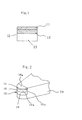
- a composite which is composed of the first sintered compact layer bonded to the second sintered compact layer, is bonded directly or bonded by an existing intermediate cemented carbide layer (13) to a tool holder as shown in Fig.1.
- a rake face of the cutting tool is the main surface of the first sintered compact layer.
- cBN had the hardest and highest heat conductivity and is chemically stable. Therefore, because of the higher concentration of cBN in the sintered compact, the sintered compact is harder, has higher heat conductivity, and is chemically stable. Accordingly, the first sintered compact layer is harder, has higher heat conductivity, and is more stable than the second sintered compact layer.
- AI or metal compounds of AI react with cBN, and create compounds such as AIB 2 . These compounds serve to firmly bond the binder and cBN or another binder.
- the first binder material contain about 3 - 15 % by weight of Co, about 1 - 5 % by weight of Al, and the remainder of WC and inevitable impurities.
- a further preferred first binder material would contain about 3 - 40 % by weight of AI and the remainder of at least one Ti-containing compound selected from a group consisting of compounds (TiM)C, (TiM)N, (TiM)(CN), an admixture thereof, and a material solid solution compound thereof, and inevitable impurities.
- M is a transition metal or metals of 4a, 5a, 6a in the periodic table, but excluding Ti.
- the second binder material contain about 2 - 30 % by weight of AI and the remainder of at least one compound selected from a group consisting of compounds (Ti,X)C, (Ti,X)N, (TiX)(CN), an admixture thereof, and a material solid solution compound thereof, and inevitable impurities.
- X is a transition metal or metals of 4a, 5a, 6a in the periodic table, but excluding li.
- a cutting edge portion (10) is composed of the first sintered compact layer (11), the second sintered compact layer (12), and cemented carbide substrate (13), as shown in Fig.1.
- the cemented carbide substrate is bonded to the second sintered layer, during a sintering under a superhigh pressure and temperature.
- the cemented carbide substrate can be excluded.
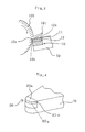
- the cutting edge portion (10) is bonded to a tip portion of a cutting tool (50) as shown in Fig.2.
- a main surface of the first sintered compact layer (11) constructs a rake face (10a) in the cutting tool.
- the thickness of the first sintered compact layer 11 is approximately 0.04 - 0.2 mm.
- the combined of the thickness of the first sintered compact layer and the second sintered compact layer is greater than approximately 0.5 mm.
- a sintered compact using W as a component of M and Hf as a component of X.
- a main surface of the first sintered compact layer constitutes a rake face in this invention.
- the volume concentration of cBN in the first sintered compact layer is higher than in the second sintered compact layer.
- Notch wear develops due to a reaction between air exposure, the work material and the cutting tool.
- Crater wear develops due to a reaction between the workmaterial and the cutting tool material at high temperatures.
- the first sintered compact layer has better notch wear resistance and crater wear resistance than the second sintered compact layer.
- a volume concentration of the binder material in the second sintered compact layer is higher than that of in the first sintered compact layer.
- Each cBN particle is strongly bonded to each other by binder material. Flank wear develops as cBN particles fall from the sintered compact because a workmaterial scours the cutting tool. Accordingly, the second sintered compact layer has higher flank wear resistance than the first sintered compact layer.
- the cutting tool is constructed so that the two types of sintered compacts are suitably arranged to correspond to the types of wear. As this construction prevents development of wear, practicable cutting time is extended.
- the thickness of the first sintered compact layer is preferably approximately 0.04-0.2 mm. Within the above range the best results with regard to wear resistance can be obtained.
- the combined thickness of the first sintered compact layer and the second sintered compact layer is preferably thicker than approximately 0.5 mm. This thickness is most suitable for a low flank wear width.
- the first sintered compact layer contains approximately 75 - 98 % by volume of cBN.
- concentration of cBN is less than about 75 % by volume, crater wear easily develops as chemical stability is reduced because of the low amount of cBN.
- concentration of cBN is more than about 98 % by volume, the amount of binder material becomes relatively lower, and the bonding strength of cBN particles is reduced.
- the second sintered compact layer contains approximately 40 - 65 % by volume of cBN.
- concentration of cBN is less than about 40 % by volume, the strength and hardness of the sintered compact is reduced and flank wear develops easily, especially when cutting high speed steel.
- concentration of cBN is more than about 65 % by volume, cBN particles easily fail from the sintered compact because the lower amount of binder material reduces the bonding strength between cBN particles and the bonding material.
- the first type of binder material contains about 3-15 wt.% Co, 1-5 wt.% Al, and the remainder of WC, and the second type of binder material contains 3-40 wt.% Al, and a compound of transition metals. These binder materials demonstrate the preferable performance of the first binder material.
- the above compositions are most useful with regard to the bonding strength of cBN particles by binder materials and with regard to wear resistance.
- the second binder material contains 2 - 30 % by weight of Al.
- concentration of AI is less than about 2 % by weight
- the bonding strength between cBN particles and binder materials weakens because of insufficient reaction between AI and cBN particles.
- concentration of AI is more than about 30 % by weight
- flank wear resistance weakens, because increasing the amount of reacted compounds, for example, AIB 2 , increases the bonding strength between cBN particles and binder materials, but decreases the flank wear resistance.
- Ti compounds in the first binder material it is preferable to employ W as a metal M, because Ti compounds containing W have excellent wear resistance.
- Ti compounds in the second binder material it is preferable to employ Hf as a metal X, because Ti compounds containing Hf have excellent heat resistance and, therefore, have excellent flank wear resistance at high speed cutting.
- a binder material powder cosisting of 5 % by weight of Co powder, 3 % by weight of AI powder and the remainder of WC powder, and cBN powder were used as the initial raw material powders for the first sintered compact layer.
- the binder material powder and the cBN powder were prepared in a volume ratio of 15 : 85.
- a raw material powder having the desired particle diameter was developed for the first sintered compact layer.
- a carbide powder a nitride powder and a carbonitride powder which contains Ti and AI powder, were mixed together as shown in Table 1 for binder material powders of the second sintered compact layer.
- binder material powders and cBN powder were prepared in a volume ratio of 40 : 60, and the prepared powders were uniformly mixed using a cemented carbide pot and cemented carbide balls.
- Raw material powders having the desired particle diameter were used for the second sintered compact layer.
- a circular plate of cemented carbide composed of WC-10 wt% Co was introduced into a Mo vessel, and then the raw material powder for the second sintered compact layer and the raw material powder for the first sintered compact layer were placed in that order on the circular plate of cemented carbide.
- This vessel was introduced into a superhigh pressure and temperature apparatus, and sintered under a pressure of 50Kb at a temperature of 1350 ° C for 15 minutes. An examination of a polished surface of the obtained composites showed that two layers of the cBN sintered compacts, which correspond to the above two raw material powders, were bonded strongly to each other and to the cemented carbide substrate.
- the aforementioned composites were worked into cutting tools, so that the first sintered compact layer of each composite constituted a rake face and the thickness of the first sintered compact layer was 0.07 mm.
- the cutting tools which were bonded to a cemented carbide tool holder, were applied to cut the outer portions of round bars with a 150 mm outside diameter made of FCD 70 (nodular cast iron).
- FCD 70 nodular cast iron
- Table 1 also shows values of the flank wear width of the cutting edges and whether chipping occurred or not.
- Binder material powders containing Co powder, AI powder and the remainder of WC powder were used for the first sintered compact layer as shown in Table 2. These binder material powders and cBN powder were prepared in a volume ratio of 12 : 88. By uniformly mixing the prepared powders using a cemented carbide pot and cemented carbide balls, raw material powders for the first sintered compact layer were developed.
- (Ti,Hf)C powder and AI powder were prepared in a weight ratio of 9 : 1 for a binder material powder of the second sintered compact layer.
- the binder material powder and cBN powder were prepared in a volume ratio of 37 : 63.
- Example 1 a circular plate of cemented carbide composed of WC-10 wt% Co was introduced into a Mo vessel and then the raw material powder for the second sintered compact layer was placed on the circular plate, and then the raw material powder for the first sintered compact layer was further placed on them.
- This vessel was introduced into a superhigh pressure and temperature apparatus, and sintered under a pressure of 45Kb at a temperature of 1300 ° C for 20 minutes. An examination of a polished surface of the obtained composites showed that two layers of the cBN sintered compact which correspond to the above two raw material powders, were bonded strongly to each other and to the cemented carbide substrate.
- the aforementioned composites were worked into cutting tools, so that the first sintered compact layer of each composite constituted a rake face and the thickness of the first sintered compact layer was as shown in Table 2.
- the cutting tools which were bonded to cemented carbide substrates, were applied to cut the outer portions of round bars with a 100 mm outside diameter made of Inconel 718.
- the cutting conditions were as follows;
- Table 2 also shows results of measured practicable cutting time and the reasons for impracticable cuttings.
- a mixed binder material powder consisting of 7 % by weight of Co powder, 4 % by weight of AI powder and the remainder of WC powder was used for the first sintered compact layer.
- the binder material powder and cBN powder were prepared in a volume ratio as shown in Table 3. By uniformly mixing the prepared powders using a cemented carbide pot and cemented carbide balls, raw material powders were developed for the first sintered compact layer.
- a mixed binder material powder consisting of (Ti,Hf)(CN) powder and AI powder in a weight ratio of 9 : 1 was used for the second sintered compact layer.
- the binder material powder and cBN powder were prepared in a volume ratio as shown in Table 3.
- Table 3 By uniformly mixing the prepared powders using a cemented carbide pot and cemented carbide balls, raw material powders were developed for the second sintered compact layer.
- a circular plate of cemented carbide composed of WC-10 wt% Co was introduced into a Mo vessel, the raw material powder for the second sintered compact layer was placed on the circular plate and then the raw material powder for the first sintered compact layer was placed on the second layer.
- This vessel was introduced into a superhigh pressure and temperature apparatus, and sintered under a pressure of 45Kb at a temperature of 1300 t for 20 minutes.
- An examination of the polished surface of the obtained composites showed that two layers of the cBN sintered compact which correspond to the above two raw material powders, were bonded strongly to each other and to the cemented carbide substrate.
- the aforementioned composites were worked into cutting tools, so that the first sintered compact layer of each composite constituted a rake face and the thickness of the first sintered compact layer was 0.05 mm.
- the cutting tools which were bonded to cemented carbide tool holders, were applied to cut the outer portions of round bars with a 100 mm outside diameter made of FCD 100 (Nodular cast iron), having a V shaped groove at a periphery of the round bars.
- FCD 100 Nodular cast iron
- Table 3 shows the results of the practicable cutting time.
- Fig.1 shows the constitution of an invented composite (10) used for a cutting edge portion of a cutting tool.
- the cutting portion (10) is composed of the first sintered compact layer (11) with a high concentration of cBN in volume ratio and the second sintered compact layer (12) with a low concentration of cBN in volume ratio.
- the thickness of the first sintered layer is at least 0.04 mm and not greater than 0.2 mm.
- Fig.2 is a side view in which the composite (10) shown in Fig.1 is bonded to a cemented carbide tool holder (50).
- the main surface of the first sintered compact laker (11) constitutes a rake face (10a).
- a flank face (10b) which has a boundary of the cutting edge (10c) between the rake face (10a) and the flank face (10b), is mainly constituted by the second sintered compact layer.
- a cemented carbide substrate (13) exists as shown in Fig.2.
- Such a configuration is obtained by bonding the cutting edge (10C) made of two layers sintered compact to a tool holder.
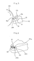
- Fig.3 shows a cross-section view of cutting process, with a workmaterial being cut by this inventions cutting tool.
- the cutting edge (10c) enters into the surface of the work, a chip (101) is developed on the rake face (10a) made of the first sintered compact layer (11).
- a binder material powder consisting of 10 % by weight of AI and the remainder or (Ti,W)C, and cBN powder was used for developing raw material powders used for the first sintered compact layer.
- the binder material powder and the cBN powder were prepared in a volume ratio or 20 : 80.
- a raw material powder having the desired particle diameter was developed for the first sintered compact layer.
- a carbide powder a nitride powder and a cabonitride powder which contain Ti and AI powder, these powders were mixed together as shown in Table 4 for binder material powders of the second sintered compact layer.
- binder material powders and cBN powder were prepared in a volume ratio of 45 : 55, and the prepared powders were uniformly mixed using a cemented carbide pot and cemented carbide balls.
- Raw material powders having the desired particle diameter were provided for the second sintered compact layer.
- a circular plate of cemented carbide was introduced into a Mo vessel, and then the raw material powder for the second sintered compact layer and
- the raw material powder for the first sintered compact layer were placed in that order on the circular plate of cemented carbide.
- This vessel was introduced into a super high pressure and temperature apparatus, and sintered under a pressure of 50Kb at a temperature of 1300 ° C for 15 minutes.
- An examination of a polished surface of the obtained composites showed that two layers of the cBN sintered compacts which correspond to the above two raw material powders, were bonded strongly to each other and to the cemented carbide substrate.
- the aforementioned composites were developed into cutting tools so that the first sintered compact layer of each composite constituted a rake face and thickness of the first sintered compact was 0.05 mm.
- the cutting tools which were bonded to cemented carbide tool holders, were applied to cut the outer portions of round bars with a 100 mm outside diameter made of FCD 60 (Nodular cast iron). The cutting conditions were as follows
- Table 4 shows the values of the flank wear width of the cutting edges and whether or not chipping occurred.
- (Ti,Hf)C powder and AI powder were prepared in a weight ratio of 9 : 1 for a binder material powder of the second sintered compact layer.
- This binder material powder and cBN powder were prepared in a volume ratio of 40 : 60.
- raw material powders for the second sintered compact layer were developed.
- a nitride powder and a carbonitride powder which contain Ti and AI powder were mixed together as shown in Table 5 for binder material powders of the first sintered compact layer.
- These binder material powders and cBN powder were prepared in a volume ratio of 22 : 78.
- Example 4 a circular plate of cemented carbide was introduced into a Mo vessel and the raw material powder for the second sintered compact layer was placed on the circular plate, and then the raw material powder for the first sintered compact layer was further placed on the second layer.
- This vessel was introduced into a superhigh pressure and temperature apparatus, and sintered under a pressure of 45Kb at a temperature of 1300 ° C for 20 minutes.
- An examination of a polished surface of the obtained composites showed that two layers of the cBN sintered compact which correspond to the above two raw material powders, were bonded strongly to each other and to the cemented carbide substrate.
- the composites were worked into a cutting tool.
- the first sintered compact layer of each composite constituted a rake face and thickness of the first sintered compact is shown in Table 5.
- the cutting tools which were bonded to a cemented carbide tool holder, were applied to cut the outer portions of round bars with a 100 mm outside diameter made of Inconel 718.
- the cutting conditions were as follows;
- Table 5 shows the results of the measured practicable cutting time and the reasons for impracticable cuttings. Notch wear occurred in sample No. 43 due to the reduced thickness in the first sintered compact layer, thus reducing practicable cutting time. In sample No. 45, there was substantial crater wear due to the high content of AI in the first sintered compact layer.
- a mixed binder material powder consisting of 15 % by weight of AI powder and the remainder of (Ti,Hf)C powder was developed for the first sintered compact layer.
- the binder material powder and cBN powder were prepared in a volume ratio as shown in Table 6.
- Raw material powders for the first sintered compact layer were obtained by the method used in example 5.
- a mixed binder material powder consisting of 10 % by weight of AI powder and the remainder of (Ti,W)(CN) was provided for the second sintered compact layer.
- This binder material powder and cBN powder were prepared in a volume ratio as shown in Table 6. By uniformly mixing the prepared powders using a cemented carbide pot and cemented carbide balls, raw material powders were developed for the second sintered compact layer.
- a circular plate of cemented carbide composed of WC-8 wt.% Co was introduced into a Mo vessel, the raw material powder for the second sintered compact layer was placed on the circular plate, and then the raw material powder for the first sintered compact layer was placed on the secnd layer.
- This vessel was introduced into a superhigh pressure and temperature apparatus, and sintered under a pressure of 45Kb at a temperature of 1250 ° C for 20 minutes. An examination of a polished surface of the obtained composites showed that two layers of the cBN sintered compact which correspond to the above two raw material powders, were bonded strongly to each other and to the cemented carbide substrate.
- the aforementioned composites were worked into cutting tools, so that the first sintered compact layer of each composite constituted a rake face and the thickness of the first sintered compact layer was 0.05 mm.
- the cutting tools which were bonded to a cemented carbide tool holder, were applied to cut the outer portions of round bars with a 100 mm outside diameter made of FCD 45 (Nodular cast iron).
- FCD 45 Nodular cast iron
- Table 6 shows the results of the measured practicable cutting time.
Landscapes
- Chemical & Material Sciences (AREA)
- Engineering & Computer Science (AREA)
- Mechanical Engineering (AREA)
- Materials Engineering (AREA)
- Chemical Kinetics & Catalysis (AREA)
- Metallurgy (AREA)
- Organic Chemistry (AREA)
- Composite Materials (AREA)
- Manufacturing & Machinery (AREA)
- Cutting Tools, Boring Holders, And Turrets (AREA)
- Ceramic Products (AREA)
Abstract
Description
- Cubic boron nitride is the hardest material next to diamond, and a sintered compact of cubic boron nitride (cBN) is employed in various cutting tools, Recently, the sintered compact in which fine cBN particles are bonded by metals, or by various ceramics using a high pressure sintering technique, has become commercially obtainable. When this sintered compact is utilized in a machining tool insert, the insert is constructed of composite material in which the hard sintered compact layer is placed only on the cutting edge portion and is bonded to a high rigidity tool holder, such as a cemented carbide.
- One example of cBN sintered compacts suitable for cutting tools is disclosed in U.S. Pat. No.4,334,928 - Yazu et al, containing 80 - 20 % by vol. of cBN and the remaining proportion of carbide, nitride, boride and silicide of elements selected from groups of the 4a and 5a periodic table, with mixtures thereof or solid solution compounds as principal components. These compounds constitute a continuous bonding phase in the texture of the sintered compact.
- An hard sintered compact for tools, in which the strength and wear resistance of a cutting edge made of the sintered compact is improved in order to eliminate the damage to the cutting edge, is disclosed in Japanese Patent Laying-Open No.62-228450. In this sintered compact, a binder includes 25 - 50 % by wt. of Al, a compound also containing Ti such as carbide of Ti, and 4 - 40 % by weight of W contained in the compound containing Ti or contained as WC. These components react with cBN in the sintering process, to produce aluminum boride, titanium boride and the like, which serve to firmly bond the binder and cBN or another binder.
- U.S. Pat. No.4,911,756 discloses a hard sintered compact for tools, including 50 - 75 % by vol. of cBN and 25 - 50 % by vol. of a binder containing 20 - 50 % by wt. of aluminum, titanium carbonitride, and the like, and 4 - 40 % by wt. of tungsten.
- Other examples of cBN sintered compacts suitable for cutting tools is disclosed in U.S. Pat. No.3,743,489 - Wentorf et al, containing greater than 70 % by volume of cBN and the remaining metallic phase consisting of aluminum and at least one alloying element selected from the group consisting of nickel, cobalt, manganese, iron, vanadium, and chromium and mixtures thereof.
- Another example of cBN sintered compounds suitable for cutting tools is disclosed in U.S. Pat. No.4,403,015 - Nakai et al. In this case a powder is used for forming the intermediate bonding layer. The bonding layer is comprised of cBN in an amount less than 70 % by volume, the residual part principally consisting of a compound selected from among carbide, nitride, carbonitride or boride of 4a, 5a, 6a transition metals of the periodic table, an admixture thereof, or a solid solution compound thereof. After pressing or in the state of powder, this bonding layer is placed on the cemented carbide substrate in a thickness less than 2 mm, and on this layer is placed a powder for forming the sintered compact containing diamond or cBN in an amount in excess of 20 % by volume, and the whole is then sintered under a superhigh pressure and temperature.
- Fig.4 is a partial side view of a prior art's cutting tool. In Fig.4, a cutting edge portion (20) made of sintered composite is bonded to a cemented carbide tool holder (50). The cutting edge portion (20) is composed of a cutting edge (20c), a rake face (20a) and a flank face (20b). The cutting edge (20c) is a boundary of the rake face and the flank face. Fig.5, is a partial cross-sectional view of a cutting process using an insert of the tool from Fig.4. As shown in Fig.5, a workmaterial (100) rotates at a high rate of speed in the direction of the arrow. The cutting tool is moved into the rotating workmaterial, and a chip (101) is made on the rake face (20a) of the cutting edge portion (20). As cutting continues, crater wear (31) develops on the rake face and flank wear (32) develops on the flank face (20b). The wear on each face is shown in Fig.6. The crater wear (31) and the flank wear (32) have a boundary of the cutting edge (20c) which contacts with a surface of the workmaterial (100). On the other hand, notch wear (33) develops at the boundary of the portion in contact with the workmaterial and air exposure. In this way, as cutting continues, partial wear, rather than uniform wear develops on the cutting edge portion.
- However, in this prior arts cutting tool, the cutting edge portion (20) has a uniform composition of cBN sintered compact in a prior art insert. As the wear progresses in a non-uniform manner, it eventually becomes, impossible to continue cutting. The non-uniform wear shortens the practicable cutting time.
- In this invention, a cutting tool has two layers of hard sintered compact of cBN. The first sintered compact layer contains about 75 - 98 % by volume of cBN and the first binder material. The first binder material contains 1 - 40 % by weight of AI element. The second sintered compact layer contains about 40 - 65 % by volume of cBN and the second binder material. The second binder material contains about 2 - 30 % by weight of Al. The first sintered compact layer is bonded to the second sintered compact layer, and this composite material is bonded directly or indirectly to a tool holder. The first sintered compact layer constitutes a rake face of the cutting tool.
- A preferred embodiment of the sintered compact is obtained by using the aforementioned first binder material which contains about 3 - 15 % by weight of Co, about 1 - 5 % by weight of Al, and the remainder of WC, or by using a binder which contains about 3 - 40 % by weight of AI and the remainder of at least one Ti-containing compound selected from a group consisting of (Ti,M)C, (Ti,M)N, (Ti,M)(CN), an admixture thereof, and a solid solution compound thereof. In this case, M is a transition metal of 4a, 5a ,6a in the periodic table excluding Ti.
- A further preferred embodiment of the sintered compact is obtained by using the aforementioned second binder material which contains about 2 - 30 % by volume of AI and at least one compound selected from a group of (TiX)C, (TiX)N, (Ti,X)(CN), an admixture thereof and a solid solution compound thereof. In this case X is a transition metal of 4a, 5a, 6a in the periodic table, excluding Ti.
- The thickness of the first sintered compact is preferably about 0.04-0.2 mm, and the combined thickness of the first sintered compact and the second sintered compact is preferably not less than 0.5 mm.
- This invention seeks to provide a cutting tool which has higher flank wear resistance, higher crater wear resistance, and higher notch wear resistance.
- Another objective of this invention is to provide a cutting tool for nodular cast iron, high speed steel, and Inconel, which are difficult to cut using prior art cutting tool materials.
- Another objective of this invention is to provide a construction of the cBN sintered compact which will lengthen practicable cutting time and prevent partial wear.
- Objective and features of this invention will become apparent from the following description of the preferred embodiment thereof, with reference to accompanying drawings, in which;
- Fig.1 shows a cross-sectional view of the hard sintered compact of the invention;
- Fig.2 is a partial side view of a cutting tool, according to the invention;
- Fig.3 is a partial cross-sectional view of a cutting process, using a cutting tool of the invention;
- Fig.4 is a partial side view of a prior art's cutting tool;
- Fig.5 is a partial cross-sectional view of a cutting process, using the cutting tool shown in Fig.4.
- Fig.6 shows the general wear portion of the cutting edge from the process in Fig.5.
- To develop this invention, the inventors involved conducted a series of experiments in order to identity a cBN sintered compact with a long practicable cutting time. The cBN sintered compact in which a concentration of cBN in a sintered compact layer of rake surface is different from a concentration of cBN in a sintered compact layer of flank face, has longer practicable cutting time than cBN sintered compact of prior arts.
- The hard sintered compact for the cutting tool of this invention utilizes a first sintered compact layer and a second sintered compact layer. The first sintered compact layer contains about 75 - 98 % by volume of cBN and the first binder material. The first binder material contains about 1 - 40 % by weight of AI element. The second sintered compact layer contains about 40 - 65 % by volume of cBN and the second binder material. The second binder material contains about 2 - 30 % by weight of AI element, and the second binder material constitutes a continuous matrix.
- A composite, which is composed of the first sintered compact layer bonded to the second sintered compact layer, is bonded directly or bonded by an existing intermediate cemented carbide layer (13) to a tool holder as shown in Fig.1. A rake face of the cutting tool is the main surface of the first sintered compact layer.
- After diamond, cBN had the hardest and highest heat conductivity and is chemically stable. Therefore, because of the higher concentration of cBN in the sintered compact, the sintered compact is harder, has higher heat conductivity, and is chemically stable. Accordingly, the first sintered compact layer is harder, has higher heat conductivity, and is more stable than the second sintered compact layer. In addition, AI or metal compounds of AI react with cBN, and create compounds such as AIB2. These compounds serve to firmly bond the binder and cBN or another binder.
- It is preferable that the first binder material contain about 3 - 15 % by weight of Co, about 1 - 5 % by weight of Al, and the remainder of WC and inevitable impurities. A further preferred first binder material would contain about 3 - 40 % by weight of AI and the remainder of at least one Ti-containing compound selected from a group consisting of compounds (TiM)C, (TiM)N, (TiM)(CN), an admixture thereof, and a material solid solution compound thereof, and inevitable impurities. In this case, M is a transition metal or metals of 4a, 5a, 6a in the periodic table, but excluding Ti. It is preferable that the second binder material contain about 2 - 30 % by weight of AI and the remainder of at least one compound selected from a group consisting of compounds (Ti,X)C, (Ti,X)N, (TiX)(CN), an admixture thereof, and a material solid solution compound thereof, and inevitable impurities. In this case, X is a transition metal or metals of 4a, 5a, 6a in the periodic table, but excluding li. A cutting edge portion (10) is composed of the first sintered compact layer (11), the second sintered compact layer (12), and cemented carbide substrate (13), as shown in Fig.1. Ordinarily, the cemented carbide substrate is bonded to the second sintered layer, during a sintering under a superhigh pressure and temperature. However, if desired, the cemented carbide substrate can be excluded. The cutting edge portion (10) is bonded to a tip portion of a cutting tool (50) as shown in Fig.2. A main surface of the first sintered compact layer (11) constructs a rake face (10a) in the cutting tool. The thickness of the first sintered
compact layer 11 is approximately 0.04 - 0.2 mm. The combined of the thickness of the first sintered compact layer and the second sintered compact layer is greater than approximately 0.5 mm. - In this invention, it is preferable to develop a sintered compact using W as a component of M and Hf as a component of X. A main surface of the first sintered compact layer constitutes a rake face in this invention. The volume concentration of cBN in the first sintered compact layer is higher than in the second sintered compact layer. Notch wear develops due to a reaction between air exposure, the work material and the cutting tool. Crater wear develops due to a reaction between the workmaterial and the cutting tool material at high temperatures. As cBN is chemically stabler than a binder material, the first sintered compact layer has better notch wear resistance and crater wear resistance than the second sintered compact layer.
- On the other hand, a volume concentration of the binder material in the second sintered compact layer is higher than that of in the first sintered compact layer. Each cBN particle is strongly bonded to each other by binder material. Flank wear develops as cBN particles fall from the sintered compact because a workmaterial scours the cutting tool. Accordingly, the second sintered compact layer has higher flank wear resistance than the first sintered compact layer.
- Therefore, in this invention, the cutting tool is constructed so that the two types of sintered compacts are suitably arranged to correspond to the types of wear. As this construction prevents development of wear, practicable cutting time is extended.
- The thickness of the first sintered compact layer is preferably approximately 0.04-0.2 mm. Within the above range the best results with regard to wear resistance can be obtained.
- The combined thickness of the first sintered compact layer and the second sintered compact layer is preferably thicker than approximately 0.5 mm. This thickness is most suitable for a low flank wear width.
- The first sintered compact layer contains approximately 75 - 98 % by volume of cBN. When the concentration of cBN is less than about 75 % by volume, crater wear easily develops as chemical stability is reduced because of the low amount of cBN. When the concentration of cBN is more than about 98 % by volume, the amount of binder material becomes relatively lower, and the bonding strength of cBN particles is reduced.
- The second sintered compact layer contains approximately 40 - 65 % by volume of cBN. When the concentration of cBN is less than about 40 % by volume, the strength and hardness of the sintered compact is reduced and flank wear develops easily, especially when cutting high speed steel. When the concentration of cBN is more than about 65 % by volume, cBN particles easily fail from the sintered compact because the lower amount of binder material reduces the bonding strength between cBN particles and the bonding material.
- In this invention, two types of binder material are preferably used for the first sintered compact layer. The first type of binder material contains about 3-15 wt.% Co, 1-5 wt.% Al, and the remainder of WC, and the second type of binder material contains 3-40 wt.% Al, and a compound of transition metals. These binder materials demonstrate the preferable performance of the first binder material. The above compositions are most useful with regard to the bonding strength of cBN particles by binder materials and with regard to wear resistance.
- The second binder material contains 2 - 30 % by weight of Al. When the concentration of AI is less than about 2 % by weight, the bonding strength between cBN particles and binder materials weakens because of insufficient reaction between AI and cBN particles. When the concentration of AI is more than about 30 % by weight, flank wear resistance weakens, because increasing the amount of reacted compounds, for example, AIB2, increases the bonding strength between cBN particles and binder materials, but decreases the flank wear resistance.
- Concerning the Ti compounds in the first binder material, it is preferable to employ W as a metal M, because Ti compounds containing W have excellent wear resistance. Concerning the Ti compounds in the second binder material, it is preferable to employ Hf as a metal X, because Ti compounds containing Hf have excellent heat resistance and, therefore, have excellent flank wear resistance at high speed cutting.
- A binder material powder cosisting of 5 % by weight of Co powder, 3 % by weight of AI powder and the remainder of WC powder, and cBN powder were used as the initial raw material powders for the first sintered compact layer. The binder material powder and the cBN powder were prepared in a volume ratio of 15 : 85. By uniformly mixing the prepared powder using a cemented carbide pot and cemented carbide balls, a raw material powder having the desired particle diameter was developed for the first sintered compact layer.
- To deveolp a carbide powder, a nitride powder and a carbonitride powder which contains Ti and AI powder, were mixed together as shown in Table 1 for binder material powders of the second sintered compact layer. These binder material powders and cBN powder were prepared in a volume ratio of 40 : 60, and the prepared powders were uniformly mixed using a cemented carbide pot and cemented carbide balls. Raw material powders having the desired particle diameter were used for the second sintered compact layer. A circular plate of cemented carbide composed of WC-10 wt% Co was introduced into a Mo vessel, and then the raw material powder for the second sintered compact layer and the raw material powder for the first sintered compact layer were placed in that order on the circular plate of cemented carbide. This vessel was introduced into a superhigh pressure and temperature apparatus, and sintered under a pressure of 50Kb at a temperature of 1350 ° C for 15 minutes. An examination of a polished surface of the obtained composites showed that two layers of the cBN sintered compacts, which correspond to the above two raw material powders, were bonded strongly to each other and to the cemented carbide substrate.
- The aforementioned composites were worked into cutting tools, so that the first sintered compact layer of each composite constituted a rake face and the thickness of the first sintered compact layer was 0.07 mm. The cutting tools, which were bonded to a cemented carbide tool holder, were applied to cut the outer portions of round bars with a 150 mm outside diameter made of FCD 70 (nodular cast iron). The cutting conditions were as follows;
-

- Table 1 also shows values of the flank wear width of the cutting edges and whether chipping occurred or not.

- Binder material powders containing Co powder, AI powder and the remainder of WC powder were used for the first sintered compact layer as shown in Table 2. These binder material powders and cBN powder were prepared in a volume ratio of 12 : 88. By uniformly mixing the prepared powders using a cemented carbide pot and cemented carbide balls, raw material powders for the first sintered compact layer were developed.
- Then, (Ti,Hf)C powder and AI powder were prepared in a weight ratio of 9 : 1 for a binder material powder of the second sintered compact layer. The binder material powder and cBN powder were prepared in a volume ratio of 37 : 63. By uniformly mixing the prepared powder using a cemented carbide pot and cemented carbide balls, a raw material powder for the second sintered compact was developed.
- As in Example 1, a circular plate of cemented carbide composed of WC-10 wt% Co was introduced into a Mo vessel and then the raw material powder for the second sintered compact layer was placed on the circular plate, and then the raw material powder for the first sintered compact layer was further placed on them. This vessel was introduced into a superhigh pressure and temperature apparatus, and sintered under a pressure of 45Kb at a temperature of 1300 ° C for 20 minutes. An examination of a polished surface of the obtained composites showed that two layers of the cBN sintered compact which correspond to the above two raw material powders, were bonded strongly to each other and to the cemented carbide substrate.
- The aforementioned composites were worked into cutting tools, so that the first sintered compact layer of each composite constituted a rake face and the thickness of the first sintered compact layer was as shown in Table 2. The cutting tools, which were bonded to cemented carbide substrates, were applied to cut the outer portions of round bars with a 100 mm outside diameter made of Inconel 718. The cutting conditions were as follows;

- In sample No. 17, the low content of AI in the first sintered compact reduced bonding strength between the cBN particles and chipping occurred. Substantial crater wear occurred in sample No. 18 due to the high content of AI in the first sintered compact layer.

- A mixed binder material powder consisting of 7 % by weight of Co powder, 4 % by weight of AI powder and the remainder of WC powder was used for the first sintered compact layer. The binder material powder and cBN powder were prepared in a volume ratio as shown in Table 3. By uniformly mixing the prepared powders using a cemented carbide pot and cemented carbide balls, raw material powders were developed for the first sintered compact layer.
- A mixed binder material powder consisting of (Ti,Hf)(CN) powder and AI powder in a weight ratio of 9 : 1 was used for the second sintered compact layer.
- The binder material powder and cBN powder were prepared in a volume ratio as shown in Table 3. By uniformly mixing the prepared powders using a cemented carbide pot and cemented carbide balls, raw material powders were developed for the second sintered compact layer.
- As in the first two examples, a circular plate of cemented carbide composed of WC-10 wt% Co was introduced into a Mo vessel, the raw material powder for the second sintered compact layer was placed on the circular plate and then the raw material powder for the first sintered compact layer was placed on the second layer. This vessel was introduced into a superhigh pressure and temperature apparatus, and sintered under a pressure of 45Kb at a temperature of 1300 t for 20 minutes. An examination of the polished surface of the obtained composites showed that two layers of the cBN sintered compact which correspond to the above two raw material powders, were bonded strongly to each other and to the cemented carbide substrate.
- The aforementioned composites were worked into cutting tools, so that the first sintered compact layer of each composite constituted a rake face and the thickness of the first sintered compact layer was 0.05 mm.

- The cutting tools, which were bonded to cemented carbide tool holders, were applied to cut the outer portions of round bars with a 100 mm outside diameter made of FCD 100 (Nodular cast iron), having a V shaped groove at a periphery of the round bars. The cutting conditions were as follows;

- Table 3 shows the results of the practicable cutting time.
- Fig.1 shows the constitution of an invented composite (10) used for a cutting edge portion of a cutting tool. The cutting portion (10) is composed of the first sintered compact layer (11) with a high concentration of cBN in volume ratio and the second sintered compact layer (12) with a low concentration of cBN in volume ratio. The thickness of the first sintered layer is at least 0.04 mm and not greater than 0.2 mm.
- Fig.2 is a side view in which the composite (10) shown in Fig.1 is bonded to a cemented carbide tool holder (50). The main surface of the first sintered compact laker (11) constitutes a rake face (10a). A flank face (10b) which has a boundary of the cutting edge (10c) between the rake face (10a) and the flank face (10b), is mainly constituted by the second sintered compact layer. A cemented carbide substrate (13) exists as shown in Fig.2. Such a configuration is obtained by bonding the cutting edge (10C) made of two layers sintered compact to a tool holder. Fig.3 shows a cross-section view of cutting process, with a workmaterial being cut by this inventions cutting tool. The cutting edge (10c) enters into the surface of the work, a chip (101) is developed on the rake face (10a) made of the first sintered compact layer (11).
- A binder material powder consisting of 10 % by weight of AI and the remainder or (Ti,W)C, and cBN powder was used for developing raw material powders used for the first sintered compact layer. The binder material powder and the cBN powder were prepared in a volume ratio or 20 : 80. By uniformly mixing the prepared powder using a cemented carbide pot and cemented carbide balls, a raw material powder having the desired particle diameter was developed for the first sintered compact layer.
- To develop a carbide powder, a nitride powder and a cabonitride powder which contain Ti and AI powder, these powders were mixed together as shown in Table 4 for binder material powders of the second sintered compact layer. These binder material powders and cBN powder were prepared in a volume ratio of 45 : 55, and the prepared powders were uniformly mixed using a cemented carbide pot and cemented carbide balls. Raw material powders having the desired particle diameter were provided for the second sintered compact layer. A circular plate of cemented carbide was introduced into a Mo vessel, and then the raw material powder for the second sintered compact layer and

- the raw material powder for the first sintered compact layer were placed in that order on the circular plate of cemented carbide. This vessel was introduced into a super high pressure and temperature apparatus, and sintered under a pressure of 50Kb at a temperature of 1300 ° C for 15 minutes. An examination of a polished surface of the obtained composites showed that two layers of the cBN sintered compacts which correspond to the above two raw material powders, were bonded strongly to each other and to the cemented carbide substrate.
- The aforementioned composites were developed into cutting tools so that the first sintered compact layer of each composite constituted a rake face and thickness of the first sintered compact was 0.05 mm. The cutting tools which were bonded to cemented carbide tool holders, were applied to cut the outer portions of round bars with a 100 mm outside diameter made of FCD 60 (Nodular cast iron). The cutting conditions were as follows
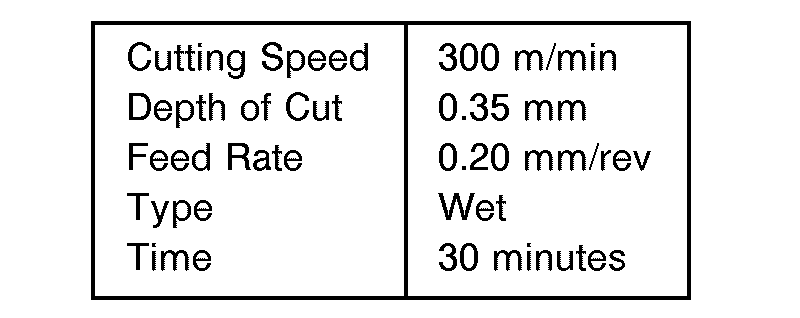
- Table 4 shows the values of the flank wear width of the cutting edges and whether or not chipping occurred.
- (Ti,Hf)C powder and AI powder were prepared in a weight ratio of 9 : 1 for a binder material powder of the second sintered compact layer. This binder material powder and cBN powder were prepared in a volume ratio of 40 : 60. By uniformly mixing the prepared powders using a cemented carbide pot and cemented carbide balls, raw material powders for the second sintered compact layer were developed. To develop a carbide powder, a nitride powder and a carbonitride powder which contain Ti and AI powder, were mixed together as shown in Table 5 for binder material powders of the first sintered compact layer. These binder material

- As in Example 4, a circular plate of cemented carbide was introduced into a Mo vessel and the raw material powder for the second sintered compact layer was placed on the circular plate, and then the raw material powder for the first sintered compact layer was further placed on the second layer. This vessel was introduced into a superhigh pressure and temperature apparatus, and sintered under a pressure of 45Kb at a temperature of 1300 ° C for 20 minutes. An examination of a polished surface of the obtained composites showed that two layers of the cBN sintered compact which correspond to the above two raw material powders, were bonded strongly to each other and to the cemented carbide substrate. The composites were worked into a cutting tool. The first sintered compact layer of each composite constituted a rake face and thickness of the first sintered compact is shown in Table 5. The cutting tools, which were bonded to a cemented carbide tool holder, were applied to cut the outer portions of round bars with a 100 mm outside diameter made of Inconel 718. The cutting conditions were as follows;

- Table 5 shows the results of the measured practicable cutting time and the reasons for impracticable cuttings. Notch wear occurred in sample No. 43 due to the reduced thickness in the first sintered compact layer, thus reducing practicable cutting time. In sample No. 45, there was substantial crater wear due to the high content of AI in the first sintered compact layer.
- A mixed binder material powder consisting of 15 % by weight of AI powder and the remainder of (Ti,Hf)C powder was developed for the first sintered compact layer. The binder material powder and cBN powder were prepared in a volume ratio as shown in Table 6. Raw material powders for the first sintered compact layer were obtained by the method used in example 5. A mixed binder material powder consisting of 10 % by weight of AI powder and the remainder of (Ti,W)(CN) was provided for the second sintered compact layer.

- This binder material powder and cBN powder were prepared in a volume ratio as shown in Table 6. By uniformly mixing the prepared powders using a cemented carbide pot and cemented carbide balls, raw material powders were developed for the second sintered compact layer.
- Next, a circular plate of cemented carbide composed of WC-8 wt.% Co was introduced into a Mo vessel, the raw material powder for the second sintered compact layer was placed on the circular plate, and then the raw material powder for the first sintered compact layer was placed on the secnd layer. This vessel was introduced into a superhigh pressure and temperature apparatus, and sintered under a pressure of 45Kb at a temperature of 1250 ° C for 20 minutes. An examination of a polished surface of the obtained composites showed that two layers of the cBN sintered compact which correspond to the above two raw material powders, were bonded strongly to each other and to the cemented carbide substrate.
- The aforementioned composites were worked into cutting tools, so that the first sintered compact layer of each composite constituted a rake face and the thickness of the first sintered compact layer was 0.05 mm. The cutting tools, which were bonded to a cemented carbide tool holder, were applied to cut the outer portions of round bars with a 100 mm outside diameter made of FCD 45 (Nodular cast iron). The cutting conditions were as follows;

- Table 6 shows the results of the measured practicable cutting time.
Claims (9)
wherein said first sintered compact layer is bonded to said second sintered compact layer and said first and second sintered compact layers are bonded to a tool holder in such a way that said first sintered compact layer constitutes a rake face of the cutting tool.
Applications Claiming Priority (4)
| Application Number | Priority Date | Filing Date | Title |
|---|---|---|---|
| JP153100/91 | 1991-06-25 | ||
| JP3153100A JP2861487B2 (en) | 1991-06-25 | 1991-06-25 | High hardness sintered cutting tool |
| JP153099/91 | 1991-06-25 | ||
| JP3153099A JP2861486B2 (en) | 1991-06-25 | 1991-06-25 | High hardness sintered cutting tool |
Publications (3)
| Publication Number | Publication Date |
|---|---|
| EP0520403A2 true EP0520403A2 (en) | 1992-12-30 |
| EP0520403A3 EP0520403A3 (en) | 1993-05-26 |
| EP0520403B1 EP0520403B1 (en) | 1995-09-27 |
Family
ID=26481816
Family Applications (1)
| Application Number | Title | Priority Date | Filing Date |
|---|---|---|---|
| EP92110630A Expired - Lifetime EP0520403B1 (en) | 1991-06-25 | 1992-06-24 | Hard sintered compact for tools |
Country Status (3)
| Country | Link |
|---|---|
| US (1) | US5395700A (en) |
| EP (1) | EP0520403B1 (en) |
| DE (1) | DE69205075T2 (en) |
Cited By (6)
| Publication number | Priority date | Publication date | Assignee | Title |
|---|---|---|---|---|
| FR2713118A1 (en) * | 1993-12-06 | 1995-06-09 | Beck August Gmbh Co | Device for finishing bores. |
| EP1551581A4 (en) * | 2002-07-08 | 2006-10-25 | Iljin Diamond Co Ltd | Sintered body with high hardness for cutting cast iron and the method for producing the same |
| WO2007069029A1 (en) * | 2005-12-12 | 2007-06-21 | Element Six (Production) (Pty) Ltd | Pcbn cutting tool components |
| WO2007122490A3 (en) * | 2006-04-21 | 2008-11-20 | Element Six Production Pty Ltd | cBN COMPOSITE MATERIAL AND TOOL |
| WO2012033930A3 (en) * | 2010-09-08 | 2012-06-07 | Smith International, Inc. | A self-sintered polycrystalline cubic boron nitride (pcbn) cutting element and a method of forming the self-sintered pcbn cutting element |
| US9233422B2 (en) | 2009-05-15 | 2016-01-12 | Element Six Limited | Superhard cutter element |
Families Citing this family (10)
| Publication number | Priority date | Publication date | Assignee | Title |
|---|---|---|---|---|
| US5679445A (en) * | 1994-12-23 | 1997-10-21 | Kennametal Inc. | Composite cermet articles and method of making |
| US5769176A (en) * | 1995-07-07 | 1998-06-23 | Sumitomo Electric Industries, Ltd. | Diamond sintered compact and a process for the production of the same |
| KR20080104752A (en) * | 2007-05-29 | 2008-12-03 | 한국야금 주식회사 | Cutting tool insert |
| EP2414119A1 (en) * | 2009-03-03 | 2012-02-08 | Diamond Innovations, Inc. | Thick thermal barrier coating for superabrasive tool |
| GB201108975D0 (en) * | 2011-05-27 | 2011-07-13 | Element Six Ltd | Superhard structure, tool element and method of making same |
| WO2014035821A1 (en) * | 2012-08-31 | 2014-03-06 | Diamond Innovations, Inc | Titanium diboride composition in pcbn |
| EP3814041A1 (en) * | 2018-06-28 | 2021-05-05 | Diamond Innovations, Inc. | Pcbn sintered compact |
| EP3854897B1 (en) * | 2018-09-19 | 2026-03-04 | Sumitomo Electric Industries, Ltd. | Production method of cubic boron nitride sintered body, cubic boron nitride sintered body, and cutting tool containing this |
| CN111889715A (en) * | 2020-07-31 | 2020-11-06 | 开封贝斯科超硬材料有限公司 | Superhard composite cutter and manufacturing method thereof |
| GB202019610D0 (en) * | 2020-12-11 | 2021-01-27 | Element Six Uk Ltd | Friction stir welding tool holder |
Family Cites Families (17)
| Publication number | Priority date | Publication date | Assignee | Title |
|---|---|---|---|---|
| AU512633B2 (en) * | 1976-12-21 | 1980-10-23 | Sumitomo Electric Industries, Ltd. | Sintered tool |
| DE3012199C2 (en) * | 1979-03-29 | 1986-08-07 | Sumitomo Electric Industries, Ltd., Osaka | Boron nitride sintered body having a matrix of MC? X?, MN? X? and / or M (CN)? x? and Al and its uses |
| US4403015A (en) * | 1979-10-06 | 1983-09-06 | Sumitomo Electric Industries, Ltd. | Compound sintered compact for use in a tool and the method for producing the same |
| GB2091763B (en) * | 1981-01-23 | 1985-07-10 | Sumitomo Electric Industries | Laminated sintered compositions including boron nitride |
| FR2498962A1 (en) * | 1981-01-30 | 1982-08-06 | Sumitomo Electric Industries | Laminated sintered diamond or cubic boron nitride tool - has intermediate layer between substrate and cutting layer comprising boron nitride and metal carbide, nitride, carbonitride or boride |
| SE457537B (en) * | 1981-09-04 | 1989-01-09 | Sumitomo Electric Industries | DIAMOND PRESSURE BODY FOR A TOOL AND WAY TO MANUFACTURE IT |
| CA1216158A (en) * | 1981-11-09 | 1987-01-06 | Akio Hara | Composite compact component and a process for the production of the same |
| KR920001585B1 (en) * | 1984-06-12 | 1992-02-20 | 스미또모 덴끼 고교 가부시끼 가이샤 | Stick compositie materials and process for preparation thereof |
| JPS62109975A (en) * | 1985-11-08 | 1987-05-21 | Toshiba Tungaloy Co Ltd | Member covered with cubic boron nitride |
| CA1313762C (en) * | 1985-11-19 | 1993-02-23 | Sumitomo Electric Industries, Ltd. | Hard sintered compact for a tool |
| JPH0621314B2 (en) * | 1985-12-28 | 1994-03-23 | 住友電気工業株式会社 | Sintered body for high hardness tool and manufacturing method thereof |
| JPH0621315B2 (en) * | 1986-01-06 | 1994-03-23 | 住友電気工業株式会社 | cBN sintered body and manufacturing method thereof |
| JP2505789B2 (en) * | 1987-01-29 | 1996-06-12 | 住友電気工業株式会社 | High hardness sintered body tool |
| US4944772A (en) * | 1988-11-30 | 1990-07-31 | General Electric Company | Fabrication of supported polycrystalline abrasive compacts |
| JPH0694580B2 (en) * | 1988-12-14 | 1994-11-24 | 住友電気工業株式会社 | Sintered body for high precision machining tools |
| US5041399A (en) * | 1989-03-07 | 1991-08-20 | Sumitomo Electric Industries, Ltd. | Hard sintered body for tools |
| CA2030350C (en) * | 1989-11-27 | 1994-08-02 | Tetsuo Nakai | Hard sintered compact for tools |
-
1992
- 1992-06-24 EP EP92110630A patent/EP0520403B1/en not_active Expired - Lifetime
- 1992-06-24 DE DE69205075T patent/DE69205075T2/en not_active Expired - Lifetime
- 1992-06-25 US US07/904,353 patent/US5395700A/en not_active Expired - Lifetime
Cited By (14)
| Publication number | Priority date | Publication date | Assignee | Title |
|---|---|---|---|---|
| FR2713118A1 (en) * | 1993-12-06 | 1995-06-09 | Beck August Gmbh Co | Device for finishing bores. |
| ES2116180A1 (en) * | 1993-12-06 | 1998-07-01 | Beck August Gmbh Co | Cutting tools |
| EP1551581A4 (en) * | 2002-07-08 | 2006-10-25 | Iljin Diamond Co Ltd | Sintered body with high hardness for cutting cast iron and the method for producing the same |
| WO2007069029A1 (en) * | 2005-12-12 | 2007-06-21 | Element Six (Production) (Pty) Ltd | Pcbn cutting tool components |
| WO2007069030A1 (en) * | 2005-12-12 | 2007-06-21 | Element Six (Production) (Pty) Ltd | Ultra-hard cutting tool components |
| WO2007069025A3 (en) * | 2005-12-12 | 2007-09-13 | Element Six Production Pty Ltd | Cutting method |
| WO2007122490A3 (en) * | 2006-04-21 | 2008-11-20 | Element Six Production Pty Ltd | cBN COMPOSITE MATERIAL AND TOOL |
| WO2007122489A3 (en) * | 2006-04-21 | 2008-11-20 | Element Six Production Pty Ltd | Method of making a cbn compact |
| US8414229B2 (en) | 2006-04-21 | 2013-04-09 | Element Six Abrasives S.A. | cBN composite material and tool |
| KR101409123B1 (en) * | 2006-04-21 | 2014-06-17 | 엘리먼트 씩스 (프로덕션) (피티와이) 리미티드 | cBN composite materials and tools |
| US9233422B2 (en) | 2009-05-15 | 2016-01-12 | Element Six Limited | Superhard cutter element |
| WO2012033930A3 (en) * | 2010-09-08 | 2012-06-07 | Smith International, Inc. | A self-sintered polycrystalline cubic boron nitride (pcbn) cutting element and a method of forming the self-sintered pcbn cutting element |
| US9028575B2 (en) | 2010-09-08 | 2015-05-12 | Element Six Limited | EDM cuttable, high CBN content solid PCBN compact |
| US9028573B2 (en) | 2010-09-08 | 2015-05-12 | Element Six Limited | EDM cuttable, high cBN content solid PCBN compact |
Also Published As
| Publication number | Publication date |
|---|---|
| EP0520403B1 (en) | 1995-09-27 |
| EP0520403A3 (en) | 1993-05-26 |
| US5395700A (en) | 1995-03-07 |
| DE69205075T2 (en) | 1996-03-21 |
| DE69205075D1 (en) | 1995-11-02 |
Similar Documents
| Publication | Publication Date | Title |
|---|---|---|
| JP5680567B2 (en) | Sintered body | |
| US4343651A (en) | Sintered compact for use in a tool | |
| US5092920A (en) | Sintered body for high-accuracy working tools | |
| EP1313887B1 (en) | Method of producing an abrasive product containing cubic boron nitride | |
| EP0251264B1 (en) | Diamond-coated tungsten carbide base sintered hard alloy material for insert of a cutting tool | |
| EP0386338B1 (en) | Hard sintered body for tools | |
| EP0223585B1 (en) | A hard sintered compact for a tool | |
| EP0520403B1 (en) | Hard sintered compact for tools | |
| JPH11505483A (en) | Corrosion and oxidation resistant grades of PCD / PCBN for wood processing applications | |
| JPS62228450A (en) | Sintered body for high hardness tools and its manufacturing method | |
| CA2217175C (en) | Hard sintered body for tool | |
| JPS601390B2 (en) | Cubic boron nitride-based ultra-high pressure sintered material for cutting tools | |
| EP0816304B1 (en) | Ceramic bonded cubic boron nitride compact | |
| JP2861486B2 (en) | High hardness sintered cutting tool | |
| US20040025631A1 (en) | Abrasive and wear resistant material | |
| EP0605755B1 (en) | Hard sintered body cutting tool | |
| JP2502362B2 (en) | High hardness sintered body for tools | |
| JPS644989B2 (en) | ||
| JPS61179848A (en) | High hardness sintered body for cutting | |
| JPH0742170B2 (en) | Cubic boron nitride based sintered body | |
| JPS58164750A (en) | Material sintered under superhigh pressure for cutting tool | |
| JP2805339B2 (en) | High density phase boron nitride based sintered body and composite sintered body | |
| JPH08225376A (en) | CBN molded product containing cobalt that can be brazed | |
| JPH075384B2 (en) | Cubic boron nitride based sintered body | |
| JPH03131573A (en) | Sintered boron nitrode base having high-density phase and composite sintered material produced by using the same |
Legal Events
| Date | Code | Title | Description |
|---|---|---|---|
| PUAI | Public reference made under article 153(3) epc to a published international application that has entered the european phase |
Free format text: ORIGINAL CODE: 0009012 |
|
| AK | Designated contracting states |
Kind code of ref document: A2 Designated state(s): DE FR GB |
|
| PUAL | Search report despatched |
Free format text: ORIGINAL CODE: 0009013 |
|
| AK | Designated contracting states |
Kind code of ref document: A3 Designated state(s): DE FR GB |
|
| 17P | Request for examination filed |
Effective date: 19930604 |
|
| 17Q | First examination report despatched |
Effective date: 19931013 |
|
| GRAA | (expected) grant |
Free format text: ORIGINAL CODE: 0009210 |
|
| AK | Designated contracting states |
Kind code of ref document: B1 Designated state(s): DE FR GB |
|
| REF | Corresponds to: |
Ref document number: 69205075 Country of ref document: DE Date of ref document: 19951102 |
|
| ET | Fr: translation filed | ||
| PLBE | No opposition filed within time limit |
Free format text: ORIGINAL CODE: 0009261 |
|
| STAA | Information on the status of an ep patent application or granted ep patent |
Free format text: STATUS: NO OPPOSITION FILED WITHIN TIME LIMIT |
|
| 26N | No opposition filed | ||
| REG | Reference to a national code |
Ref country code: GB Ref legal event code: IF02 |
|
| PGFP | Annual fee paid to national office [announced via postgrant information from national office to epo] |
Ref country code: FR Payment date: 20020610 Year of fee payment: 11 |
|
| PGFP | Annual fee paid to national office [announced via postgrant information from national office to epo] |
Ref country code: GB Payment date: 20020619 Year of fee payment: 11 |
|
| PG25 | Lapsed in a contracting state [announced via postgrant information from national office to epo] |
Ref country code: GB Free format text: LAPSE BECAUSE OF NON-PAYMENT OF DUE FEES Effective date: 20030624 |
|
| GBPC | Gb: european patent ceased through non-payment of renewal fee |
Effective date: 20030624 |
|
| PG25 | Lapsed in a contracting state [announced via postgrant information from national office to epo] |
Ref country code: FR Free format text: LAPSE BECAUSE OF NON-PAYMENT OF DUE FEES Effective date: 20040227 |
|
| REG | Reference to a national code |
Ref country code: FR Ref legal event code: ST |
|
| PGFP | Annual fee paid to national office [announced via postgrant information from national office to epo] |
Ref country code: DE Payment date: 20110622 Year of fee payment: 20 |
|
| REG | Reference to a national code |
Ref country code: DE Ref legal event code: R071 Ref document number: 69205075 Country of ref document: DE |
|
| REG | Reference to a national code |
Ref country code: DE Ref legal event code: R071 Ref document number: 69205075 Country of ref document: DE |
|
| PG25 | Lapsed in a contracting state [announced via postgrant information from national office to epo] |
Ref country code: DE Free format text: LAPSE BECAUSE OF EXPIRATION OF PROTECTION Effective date: 20120626 |