EP0520073B1 - Method of continuous processing of wire rod - Google Patents
Method of continuous processing of wire rod Download PDFInfo
- Publication number
- EP0520073B1 EP0520073B1 EP91902735A EP91902735A EP0520073B1 EP 0520073 B1 EP0520073 B1 EP 0520073B1 EP 91902735 A EP91902735 A EP 91902735A EP 91902735 A EP91902735 A EP 91902735A EP 0520073 B1 EP0520073 B1 EP 0520073B1
- Authority
- EP
- European Patent Office
- Prior art keywords
- wire material
- wire
- electrolytic
- electrolytic polishing
- bath
- Prior art date
- Legal status (The legal status is an assumption and is not a legal conclusion. Google has not performed a legal analysis and makes no representation as to the accuracy of the status listed.)
- Expired - Lifetime
Links
Images


Classifications
-
- B—PERFORMING OPERATIONS; TRANSPORTING
- B23—MACHINE TOOLS; METAL-WORKING NOT OTHERWISE PROVIDED FOR
- B23H—WORKING OF METAL BY THE ACTION OF A HIGH CONCENTRATION OF ELECTRIC CURRENT ON A WORKPIECE USING AN ELECTRODE WHICH TAKES THE PLACE OF A TOOL; SUCH WORKING COMBINED WITH OTHER FORMS OF WORKING OF METAL
- B23H9/00—Machining specially adapted for treating particular metal objects or for obtaining special effects or results on metal objects
- B23H9/18—Producing external conical surfaces or spikes
-
- B—PERFORMING OPERATIONS; TRANSPORTING
- B23—MACHINE TOOLS; METAL-WORKING NOT OTHERWISE PROVIDED FOR
- B23H—WORKING OF METAL BY THE ACTION OF A HIGH CONCENTRATION OF ELECTRIC CURRENT ON A WORKPIECE USING AN ELECTRODE WHICH TAKES THE PLACE OF A TOOL; SUCH WORKING COMBINED WITH OTHER FORMS OF WORKING OF METAL
- B23H9/00—Machining specially adapted for treating particular metal objects or for obtaining special effects or results on metal objects
- B23H9/005—Machining elongated bodies, e.g. rods
-
- A—HUMAN NECESSITIES
- A61—MEDICAL OR VETERINARY SCIENCE; HYGIENE
- A61M—DEVICES FOR INTRODUCING MEDIA INTO, OR ONTO, THE BODY; DEVICES FOR TRANSDUCING BODY MEDIA OR FOR TAKING MEDIA FROM THE BODY; DEVICES FOR PRODUCING OR ENDING SLEEP OR STUPOR
- A61M25/00—Catheters; Hollow probes
- A61M25/01—Introducing, guiding, advancing, emplacing or holding catheters
- A61M25/09—Guide wires
Definitions
- the present invention relates to a method of processing wire material and a processing device therefor at the times of intending to make the tip of wire materials such as guide wire for catheter thin and flexible by tapering, and the like.
- the guide wire for catheter used by interposing into human body, etc. it is required to be interposed easily making the tip portion of wire material thin and flexible by tapering.
- a portion of 100 to 200 mm at the tip of wire material of around 0.5 mm ⁇ is tapered to finish the diameter of the utmost tip portion to around 0.12 mm ⁇ is used.
- This traditional electrolytic polishing method is however a method of polishing batch wise by dipping one by one into the electrolytic polishing bath while moving up and down manually, hence there arise the problems that the shape of tapered portion varies widely and many workers are required resulting in high cost.
- acetic acid-perchloric acid bath has a strong bad smell and gives somewhat poor surface gloss after polishing
- fluoric acid-nitric acid bath has a strong bad smell, gives poor surface gloss after polishing and requires high cost for effluent treatment from the pollution problem.
- the sulfuric acid-fluoric acid-glycerine bath has no bad smell, but it gives poor surface gloss and requires high cost for effluent treatment.
- GB-A-557 386 shows an apparatus for annealing or polishing tungsten wire.
- This apparatus consists of means for continuously feeding the metal wire through an electrolytic bath containing an electrolyte, a cathode of tubular form completely or nearly completely encircling the wire, a contact engaging said moving wire, means for connecting said contact to the positive side of a source of a power supply and means for connecting the afore-mentioned cathode to the negative side of said supply.
- US 2,605,218 shows a method of making a tapered wire by means of a plurality of electrolytic cells arranged in a row.
- Said wire includes two sections, each equal in length to the length of said row. The method consists in inserting the first of said sections in said cells, passing current through said cells with said wire functioning as an anode, pulling said first section actually out of said cells, and the second section actually into said cells at a constant speed, thereby tapering said first section and pulling said second section actually out of said cells at a predetermined slower constant speed, so that a taper is produced on the second section having the same slope as the taper produced on the first section.
- the invention has been made as a result of diligent investigations to solve such problems and is concerned with a method of continuously processing wire material according to claim 1.
- the invention is concerned with the use of a device for continuously processing wire material according to claim 6.
- processing portion for example, tapered portion, grooved portion, etc.
- the feeding speed of wire material-advancing device is desirable to be variable and the generating current of power source-generating device is also desirable to be variable.
- composition of wire material a superelastic alloy substituted part of Ni or/and Ti in 50.5 to 53.0 % of Ni and 49.5 to 47.0 % of Ti with any one kind or two or more kinds of Cr, Fe, Co, Mo, V, Pd, W and Cu within a range of 0.01 to 5.0 % of each is used.
- the electrolytic polishing bath to be used for said continuously processing device it is effective to use a bath comprising 10 to 50 vol. % of trivalent alcohol, 5 to 20 vol. % of perchloric acid and the balance of monovalent alcohol.
- ethanol or methanol is desirable and, as the trivalent alcohol, glycerine is desirable.
- a long processed material (Fig. 4) can be obtained, hence, if cutting at point A and point A', tapered material at both ends is obtained and, if cutting at point A and point D, tapered material at one end is obtained.
- the turning on-off of power source may be performed manually, but it goes without saying that it can be automated briefly by using feedback circuit through the detection of winding length.
- Fig. 6 shows an outline diagram of the inventive device and Fig. 7 shows a partially magnified diagram.
- numeral 11 is a supply reel
- numeral 12 is a wire material
- numeral 13 is an anodic electricity-supply device (diagram shows electricity-supply roll)
- numeral 14 is an electrolytic tub
- numeral 15 is an electrolytic polishing bath
- numeral 16 is a cathode
- numeral 17 is a wash tub
- numeral 18 is a drying device
- numeral 19 is a wire material-advancing device
- numeral 20 is a power source-generating device
- numeral 21 is a winding reel, respectively.
- the electrolytic polishing by the inventive device is performed, as shown in Fig. 7, in a way that electricity is supplied to anode by anodic electricity-supply device 13 provided outside the electrolytic tub, on the other hand, a cylindrical electrode formed so as to locate at both sides or to envelop the whole circumference of wire material securing a fixed distance from the wire material in electrolytic solution (i.e. electrolytic polishing bath) is provided to make this the cathode 16, and a variable fixed current is turned on by means of power source-generating device while allowing the wire material to run at a constant or variable appropriate speed by means of wire material-advancing device 19. Thereby, the tapering in arbitrary shape can be achieved.
- the tapering length is a contacting length of electrolytic solution with wire material
- the length of electrolytic tub is altered fitting to the desired tapering length.
- perchloric acid was restricted to 5 to 20 vol. % is because of that, in the case of being under 5 vol. %, the stability of solution is damaged due to the consumption during electrolytic polishing and, if being over 20 vol. %, the safety becomes problematic and the surface gloss is injured.
- trivalent alcohol was restricted to 10 to 50 vol. % is because of that, in the case of being under 10 vol. %, the viscosity of both is low and the smoothness of surface is poor and, if being over 50 vol. %, the viscosity is too high resulting in difficult agitation of bath and generation of color unevenness.
- methanol or ethanol is excellent from the points of availability and viscosity.
- glycerine is excellent from the points of cost and availability.
- Fig. 1 shows one example of the inventive method and is a diagram illustrating the state at the time of electricity being turned on
- Fig. 2 is a diagram illustrating the state at the time of electricity being turned off similarly
- Fig. 3 and Fig. 4 are side views showing one example of wire material obtainable by the inventive method
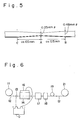
- Fig. 5 is a side view showing the wire material obtained in Example 1 and 2 of the invention
- Fig. 6 is an outline diagram showing one example of the inventive device
- Fig. 7 is a partially magnified diagram of Fig. 6
- Fig. 8 is a chart showing the feeding speed of wire material used in Example 3 and 5 of the invention
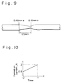
- Fig. 9 is a side view showing the tapered wire material obtained in Example 3 and 5
- Fig. 10 is a chart showing the turned-on current used in Example 4 and 6.
- the electrolytic polishing was conducted for 10 minutes at ambient temperature applying a voltage of 25 V.
- Example 7 - 9 and Comparative example 1 With respect to above-mentioned Example 7 - 9 and Comparative example 1, the smell of bath and the surface situation were observed and, in addition, the dissolution rate of wire material was determined, the results of which are put down in Table 1.
- Table 1 Surface Situation Smell of bath Dissolution rate Example 7 o No 12 ⁇ m/min
- Example 8 o No 14 ⁇ m/min Comparative example 1 X Yes 8 ⁇ m/min
- the surface situation was good, no smell of bath was felt, and the dissolution rate was also as fast as 12 to 14 ⁇ m/min.
- the change in wire diameter in the longitudinal direction of wire material can be controlled arbitrarily and the processings such as tapering and joggling can be given efficiently and yet with high precision.
- the electrolytic polishing bath of the inventive processing device if using monovalent alcohol and trivalent alcohol, no bad smell is felt and they are suitable for efficiently obtaining the polished material of Ni-Ti alloy with good surface situation.
Abstract
Description
- The present invention relates to a method of processing wire material and a processing device therefor at the times of intending to make the tip of wire materials such as guide wire for catheter thin and flexible by tapering, and the like.
- For the guide wire for catheter used by interposing into human body, etc., it is required to be interposed easily making the tip portion of wire material thin and flexible by tapering. As an example, such one that a portion of 100 to 200 mm at the tip of wire material of around 0.5 mm⌀ is tapered to finish the diameter of the utmost tip portion to around 0.12 mm⌀ is used.
- Traditionally, this tapering has been made first by mechanical polishing, but the mechanical polishing has a drawback to lose the superelasticity for the Ni-Ti superelastic alloy used usually as a guide wire for catheter. In recent, therefore, an electrolytic polishing method by batch process is adopted, wherein the tip portion of wire material is dipped, for example, into a polishing solution having a composition comprising 92 % of CH3COOH and 8 % of HClO4, into a polishing solution having a composition comprising 20 % of HF and 80 % of HNO3, or into a polishing solution having a composition comprising 60 % of H2SO4, 30 % of HF and 10 % of glycerine.
- This traditional electrolytic polishing method is however a method of polishing batch wise by dipping one by one into the electrolytic polishing bath while moving up and down manually, hence there arise the problems that the shape of tapered portion varies widely and many workers are required resulting in high cost.
- Moreover, traditional electrolytic polishing baths have following problems. Namely, the acetic acid-perchloric acid bath has a strong bad smell and gives somewhat poor surface gloss after polishing, and the fluoric acid-nitric acid bath has a strong bad smell, gives poor surface gloss after polishing and requires high cost for effluent treatment from the pollution problem. The sulfuric acid-fluoric acid-glycerine bath has no bad smell, but it gives poor surface gloss and requires high cost for effluent treatment.
- GB-A-557 386 shows an apparatus for annealing or polishing tungsten wire. This apparatus consists of means for continuously feeding the metal wire through an electrolytic bath containing an electrolyte, a cathode of tubular form completely or nearly completely encircling the wire, a contact engaging said moving wire, means for connecting said contact to the positive side of a source of a power supply and means for connecting the afore-mentioned cathode to the negative side of said supply.
- Finally, US 2,605,218 shows a method of making a tapered wire by means of a plurality of electrolytic cells arranged in a row. Said wire includes two sections, each equal in length to the length of said row. The method consists in inserting the first of said sections in said cells, passing current through said cells with said wire functioning as an anode, pulling said first section actually out of said cells, and the second section actually into said cells at a constant speed, thereby tapering said first section and pulling said second section actually out of said cells at a predetermined slower constant speed, so that a taper is produced on the second section having the same slope as the taper produced on the first section.
- The invention has been made as a result of diligent investigations to solve such problems and is concerned with a method of continuously processing wire material according to claim 1.
- Here, it is preferable from the point of efficiency that, when the nonprocessing portion passes through the electrolytic polishing bath, the wire speed is made high.
- Further, the invention is concerned with the use of a device for continuously processing wire material according to claim 6.
- Here, as the shapes of processing portion, for example, tapered portion, grooved portion, etc. are intended, and, in order to make this tapered shape, grooved shape or the like arbitrarily variable, the feeding speed of wire material-advancing device is desirable to be variable and the generating current of power source-generating device is also desirable to be variable.
- Besides, as the composition of wire material, a superelastic alloy substituted part of Ni or/and Ti in 50.5 to 53.0 % of Ni and 49.5 to 47.0 % of Ti with any one kind or two or more kinds of Cr, Fe, Co, Mo, V, Pd, W and Cu within a range of 0.01 to 5.0 % of each is used.
- Moreover, as the electrolytic polishing bath to be used for said continuously processing device, it is effective to use a bath comprising 10 to 50 vol. % of trivalent alcohol, 5 to 20 vol. % of perchloric acid and the balance of monovalent alcohol.
- And, as the monovalent alcohol, ethanol or methanol is desirable and, as the trivalent alcohol, glycerine is desirable.
- In following, the invention will be illustrated in more detail using diagrams.
- As shown in Fig. 1, when tapering a wire material 1 while passing it through the electrolytic polishing bath, electricity is turned on between
cathode 3 and electricity-supply roll 4 at the time of point A of wire material having reached the inlet of bath and said electricity is turned off at the time of point A having reached the outlet of bath (Fig. 2). By this procedure, the wire material is tapered in such a shape that the wire diameter increases gradually towards both ends making point A as a center as shown in Fig. 3. And, the length of the portion to be tapered AC is approximately equal to the length of electrolytic polishing bath AB (i.e. the length of wire material existed initially in the bath) and the distance between A and C and that between A and B are processed almost symmetrically. Besides, the diameter of point A becoming the minimum diameter of wire material is determined depending on the current to be turned on. - Moreover, by periodically turning on-off the current at a fixed period, a long processed material (Fig. 4) can be obtained, hence, if cutting at point A and point A', tapered material at both ends is obtained and, if cutting at point A and point D, tapered material at one end is obtained.
- The turning on-off of power source may be performed manually, but it goes without saying that it can be automated briefly by using feedback circuit through the detection of winding length.
- It is extremely effective from the point of cost reduction that, when passing the portion not to be tapered through the electrolytic polishing bath, the wire speed is made high, thus enhancing the productivity.
- Further, the processing device will be illustrated in detail. Fig. 6 shows an outline diagram of the inventive device and Fig. 7 shows a partially magnified diagram. In Fig. 6 and Fig. 7, numeral 11 is a supply reel,
numeral 12 is a wire material,numeral 13 is an anodic electricity-supply device (diagram shows electricity-supply roll),numeral 14 is an electrolytic tub,numeral 15 is an electrolytic polishing bath,numeral 16 is a cathode,numeral 17 is a wash tub,numeral 18 is a drying device,numeral 19 is a wire material-advancing device, numeral 20 is a power source-generating device, andnumeral 21 is a winding reel, respectively. - The electrolytic polishing by the inventive device is performed, as shown in Fig. 7, in a way that electricity is supplied to anode by anodic electricity-
supply device 13 provided outside the electrolytic tub, on the other hand, a cylindrical electrode formed so as to locate at both sides or to envelop the whole circumference of wire material securing a fixed distance from the wire material in electrolytic solution (i.e. electrolytic polishing bath) is provided to make this thecathode 16, and a variable fixed current is turned on by means of power source-generating device while allowing the wire material to run at a constant or variable appropriate speed by means of wire material-advancingdevice 19. Thereby, the tapering in arbitrary shape can be achieved. - Since the tapering length is a contacting length of electrolytic solution with wire material, the length of electrolytic tub is altered fitting to the desired tapering length. For Controlling the shape of taper, it is only necessary to experimentally determine beforehand through the change in said feeding speed of wire material or the change in electrolytic current so that the desired shape can be achieved.
- Next, the explanation will be made in detail about the electrolytic bath.
- The reason why perchloric acid was restricted to 5 to 20 vol. % is because of that, in the case of being under 5 vol. %, the stability of solution is damaged due to the consumption during electrolytic polishing and, if being over 20 vol. %, the safety becomes problematic and the surface gloss is injured. Moreover, the reason why trivalent alcohol was restricted to 10 to 50 vol. % is because of that, in the case of being under 10 vol. %, the viscosity of both is low and the smoothness of surface is poor and, if being over 50 vol. %, the viscosity is too high resulting in difficult agitation of bath and generation of color unevenness.
- As the monovalent alcohol, methanol or ethanol is excellent from the points of availability and viscosity.
- As the trivalent alcohol, glycerine is excellent from the points of cost and availability.
- Fig. 1 shows one example of the inventive method and is a diagram illustrating the state at the time of electricity being turned on, Fig. 2 is a diagram illustrating the state at the time of electricity being turned off similarly, Fig. 3 and Fig. 4 are side views showing one example of wire material obtainable by the inventive method, Fig. 5 is a side view showing the wire material obtained in Example 1 and 2 of the invention, Fig. 6 is an outline diagram showing one example of the inventive device, Fig. 7 is a partially magnified diagram of Fig. 6, Fig. 8 is a chart showing the feeding speed of wire material used in Example 3 and 5 of the invention, Fig. 9 is a side view showing the tapered wire material obtained in Example 3 and 5, and Fig. 10 is a chart showing the turned-on current used in Example 4 and 6.
- For illustrating the invention in more detail, it will be minutely described based on the examples.
- Using a 0.48 mm⌀ NiTi alloy wire (Ni:Ti = 50.9:49.1 at %), the electrolytic polishing was conducted under following conditions:
(1) Composition of electrolytic polishing bathEthanol 72 % Glycerine 20 % Perchloric acid 8 %
(2) Bath temperature 25 °C - 30 °C
(3)Electrolytic tub Length 125 mm
(4) Wire speed Constant speed of 33 mm/min
(5) Total current turned on 1.2 A
(6) On-off timing According to Fig. 1 and Fig. 2 - The shape of wire material thus obtained is shown in Fig. 5. As evident from Fig. 5, smooth tapering is given for the shape of taper obtained according to the invention.
- Moreover, the comparison of electrolytic solutions is as follows:
- Employing a 1 mm⌀ Ni-Ti alloy (50.9 - 49.1 at %) wire material and using a bath comprising 50 vol. % of methanol, 40 vol. % of glycerine and 10 vol. % of perchloric acid, the electrolytic polishing was conducted for 10 minutes at ambient temperature applying a voltage of 25 V.
- Employing the same wire material and using a bath comprising 30 vol. % of ethanol, 50 vol. % of glycerine and 20 vol. % of perchloric acid, the electrolytic polishing was conducted for 10 minutes at ambient temperature applying a voltage of 25 V.
- Similarly, the experiment was conducted in a bath of HF:HNO3 = 1:4 (molar ratio).
- With respect to above-mentioned Example 7 - 9 and Comparative example 1, the smell of bath and the surface situation were observed and, in addition, the dissolution rate of wire material was determined, the results of which are put down in Table 1.
Table 1 Surface Situation Smell of bath Dissolution rate Example 7 ⓞ No 12 µm/min Example 8 ⓞ No 14 µm/min Comparative example 1 X Yes 8 µm/min - As evident from Table 1, in the examples of the invention, the surface situation was good, no smell of bath was felt, and the dissolution rate was also as fast as 12 to 14 µm/min.
- On the contrary, in comparative example, the surface situation was not good, bad smell was felt strongly, and the dissolution rate was slow.
- As described above, in accordance with the invention, the change in wire diameter in the longitudinal direction of wire material can be controlled arbitrarily and the processings such as tapering and joggling can be given efficiently and yet with high precision.
- Moreover, for the electrolytic polishing bath of the inventive processing device, if using monovalent alcohol and trivalent alcohol, no bad smell is felt and they are suitable for efficiently obtaining the polished material of Ni-Ti alloy with good surface situation.
Claims (8)
- A method of continuously processing parts of a wire material by electrolytic polishing,
by continuously passing a long wire material of a superelastic alloy substituted part of Ni or/and Ti in 50.5 to 53.0 % of Ni and 49.5 to 47.0 % of Ti with any one kind or two or more kinds of Cr, Fe, Co, Mo, V, Pd, W and Cu within a range of 0.01 to 5.0 % of each through an electrolytic polishing bath with a cathode installed therein, the electrolytic polishing bath comprising 10 to 50 vol. % of trivalent alcohol, 5 to 20 vol % of perchloric acid and the balance of monovalent alcohol, and
by turning electricity on only when the processing portion passes through said electrolytic polishing bath. - A method according to claim 1, wherein, when the non-processing portion passes through the electrolytic polishing bath, the wire speed is made high.
- A method according to claim 1 or 2, wherein the processing of the wire material is tapering or grooving.
- A method according to any of the preceding claims wherein the monovalent alcohol is ethanol or methanol.
- A method according to any of the preceding claims wherein the trivalent alcohol is glycerine.
- A use of a device for carrying out a method according to any one of the preceding claims, said device comprising
an electrolytic tub (14) having the same length as that of a processing portion of the wire material, a wire material-advancing device (19) for allowing the wire material to pass through the electrolytic tub, a cathode (16) provided in the electrolytic tub, an anodic electricity-supply device (13) for wire material, and a power source generating device (0). - A use according to claim 6, wherein the wire material advancing device can vary the wire speed.
- A use according to claim 5, wherein the power source generating device can vary the current.
Applications Claiming Priority (1)
| Application Number | Priority Date | Filing Date | Title |
|---|---|---|---|
| PCT/JP1991/000027 WO1992012819A1 (en) | 1991-01-16 | 1991-01-16 | Method of and device for continuous processing of wire rod |
Publications (3)
| Publication Number | Publication Date |
|---|---|
| EP0520073A1 EP0520073A1 (en) | 1992-12-30 |
| EP0520073A4 EP0520073A4 (en) | 1993-06-02 |
| EP0520073B1 true EP0520073B1 (en) | 1996-08-14 |
Family
ID=14014212
Family Applications (1)
| Application Number | Title | Priority Date | Filing Date |
|---|---|---|---|
| EP91902735A Expired - Lifetime EP0520073B1 (en) | 1991-01-16 | 1991-01-16 | Method of continuous processing of wire rod |
Country Status (8)
| Country | Link |
|---|---|
| US (1) | US5334294A (en) |
| EP (1) | EP0520073B1 (en) |
| KR (1) | KR0185154B1 (en) |
| AU (1) | AU650243B2 (en) |
| CA (1) | CA2078335A1 (en) |
| DE (1) | DE69121397T2 (en) |
| DK (1) | DK0520073T3 (en) |
| WO (1) | WO1992012819A1 (en) |
Cited By (4)
| Publication number | Priority date | Publication date | Assignee | Title |
|---|---|---|---|---|
| US7918011B2 (en) | 2000-12-27 | 2011-04-05 | Abbott Cardiovascular Systems, Inc. | Method for providing radiopaque nitinol alloys for medical devices |
| US7938843B2 (en) | 2000-11-02 | 2011-05-10 | Abbott Cardiovascular Systems Inc. | Devices configured from heat shaped, strain hardened nickel-titanium |
| US7942892B2 (en) | 2003-05-01 | 2011-05-17 | Abbott Cardiovascular Systems Inc. | Radiopaque nitinol embolic protection frame |
| US7976648B1 (en) | 2000-11-02 | 2011-07-12 | Abbott Cardiovascular Systems Inc. | Heat treatment for cold worked nitinol to impart a shape setting capability without eventually developing stress-induced martensite |
Families Citing this family (13)
| Publication number | Priority date | Publication date | Assignee | Title |
|---|---|---|---|---|
| US6682608B2 (en) | 1990-12-18 | 2004-01-27 | Advanced Cardiovascular Systems, Inc. | Superelastic guiding member |
| JP3922728B2 (en) * | 1993-02-01 | 2007-05-30 | 住友電気工業株式会社 | Metal-coated superconducting wire manufacturing method and electropolishing apparatus |
| US5437282A (en) * | 1993-10-29 | 1995-08-01 | Boston Scientific Corporation | Drive shaft for acoustic imaging catheters and flexible catheters |
| SE511209C2 (en) * | 1994-12-12 | 1999-08-23 | Sandvik Ab | Method for obtaining well-defined oak gradients on inserts with electropolishing technology |
| US5993638A (en) * | 1997-05-23 | 1999-11-30 | Sandvik Ab | Method for obtaining well-defined edge radii on cutting tool inserts in combination with a high surface finish over the whole insert by electropolishing technique |
| US6352515B1 (en) * | 1999-12-13 | 2002-03-05 | Advanced Cardiovascular Systems, Inc. | NiTi alloyed guidewires |
| US7455738B2 (en) * | 2003-10-27 | 2008-11-25 | Paracor Medical, Inc. | Long fatigue life nitinol |
| CN102758241B (en) * | 2011-04-29 | 2016-04-27 | 通用电气公司 | Remove outer field device, the system and method for metal or metal composite wire rod |
| US11229490B2 (en) | 2013-06-26 | 2022-01-25 | Corindus, Inc. | System and method for monitoring of guide catheter seating |
| US10779775B2 (en) * | 2013-06-26 | 2020-09-22 | Corindus, Inc. | X-ray marker guided automated guide wire or working catheter advancement |
| CN110106545B (en) * | 2019-05-08 | 2020-09-15 | 广东脉搏医疗科技有限公司 | Nickel-titanium alloy electrochemical polishing solution, surface treatment method and left atrial appendage occluder |
| CN110339460B (en) * | 2019-07-17 | 2022-04-01 | 深圳市凯思特医疗科技股份有限公司 | Manufacturing method of loach guide wire |
| CN111621841B (en) * | 2020-05-21 | 2022-05-10 | 南京理工大学 | TiAl single crystal EBSD sample-based electrolytic polishing solution and electrolytic method thereof |
Family Cites Families (7)
| Publication number | Priority date | Publication date | Assignee | Title |
|---|---|---|---|---|
| GB557386A (en) * | 1942-05-11 | 1943-11-18 | Ernest Thomas James Tapp | An improved apparatus for electrolytically treating metal |
| US2605218A (en) * | 1944-03-09 | 1952-07-29 | Borg George W Corp | Electrolytic method and apparatus for the manufacture of tapered conductors |
| JPS53104538A (en) * | 1977-02-24 | 1978-09-11 | Toshiba Corp | Electrolytic processing apparatus |
| AT368196B (en) * | 1980-01-22 | 1982-09-27 | Computer Process Automations G | DEVICE FOR PRODUCING GALVANICALLY COATED WIRE |
| FR2509721A1 (en) * | 1981-07-17 | 1983-01-21 | Rhone Poulenc Chim Base | PROCESS FOR CARBONYLATION OF METHYL ACETATE |
| DE3216748A1 (en) * | 1982-05-05 | 1983-11-10 | Inovan-Stroebe GmbH & Co KG, 7534 Birkenfeld | SELECTIVE GALVANIZING METHOD FOR METAL WIRE |
| US5066370A (en) * | 1990-09-07 | 1991-11-19 | International Business Machines Corporation | Apparatus, electrochemical process, and electrolyte for microfinishing stainless steel print bands |
-
1991
- 1991-01-16 AU AU70569/91A patent/AU650243B2/en not_active Ceased
- 1991-01-16 DK DK91902735.9T patent/DK0520073T3/en active
- 1991-01-16 CA CA002078335A patent/CA2078335A1/en not_active Abandoned
- 1991-01-16 DE DE69121397T patent/DE69121397T2/en not_active Expired - Fee Related
- 1991-01-16 WO PCT/JP1991/000027 patent/WO1992012819A1/en active IP Right Grant
- 1991-01-16 US US07/923,800 patent/US5334294A/en not_active Expired - Lifetime
- 1991-01-16 KR KR1019920702238A patent/KR0185154B1/en not_active IP Right Cessation
- 1991-01-16 EP EP91902735A patent/EP0520073B1/en not_active Expired - Lifetime
Cited By (4)
| Publication number | Priority date | Publication date | Assignee | Title |
|---|---|---|---|---|
| US7938843B2 (en) | 2000-11-02 | 2011-05-10 | Abbott Cardiovascular Systems Inc. | Devices configured from heat shaped, strain hardened nickel-titanium |
| US7976648B1 (en) | 2000-11-02 | 2011-07-12 | Abbott Cardiovascular Systems Inc. | Heat treatment for cold worked nitinol to impart a shape setting capability without eventually developing stress-induced martensite |
| US7918011B2 (en) | 2000-12-27 | 2011-04-05 | Abbott Cardiovascular Systems, Inc. | Method for providing radiopaque nitinol alloys for medical devices |
| US7942892B2 (en) | 2003-05-01 | 2011-05-17 | Abbott Cardiovascular Systems Inc. | Radiopaque nitinol embolic protection frame |
Also Published As
| Publication number | Publication date |
|---|---|
| US5334294A (en) | 1994-08-02 |
| EP0520073A4 (en) | 1993-06-02 |
| AU7056991A (en) | 1992-08-27 |
| CA2078335A1 (en) | 1992-07-17 |
| DE69121397T2 (en) | 1997-01-16 |
| EP0520073A1 (en) | 1992-12-30 |
| KR0185154B1 (en) | 1999-05-01 |
| AU650243B2 (en) | 1994-06-16 |
| DK0520073T3 (en) | 1996-12-16 |
| WO1992012819A1 (en) | 1992-08-06 |
| DE69121397D1 (en) | 1996-09-19 |
Similar Documents
| Publication | Publication Date | Title |
|---|---|---|
| EP0520073B1 (en) | Method of continuous processing of wire rod | |
| KR100311241B1 (en) | Shaped-tube electrolytic polishing process | |
| BR9400478A (en) | Process for stripping and passivating stainless steel without using nitric acid | |
| KR20220006525A (en) | Wire electrode for wire-cut electric discharge machining having carbonaceous surface layer and manufacturing method thereof | |
| US5602488A (en) | Method and apparatus for adjusting sectional area ratio of metal-covered electric wire | |
| DE2027156C3 (en) | Process for anodic polishing of niobium parts | |
| EP0482565A2 (en) | Electrolytic process for stripping a metal coating from a titanium based metal substrate | |
| JPH0214020A (en) | Metal fiber obtained by drawing metal bundle | |
| JP2001225228A5 (en) | ||
| RU2085616C1 (en) | Process for pickling of high-grade steel | |
| US2725352A (en) | Methods of and apparatus for dissolving surface projections, electropolishing and passivating metallic tapes | |
| JP2002103146A (en) | Electrochemical machining method for deformed hole | |
| JP4452385B2 (en) | Electrolytic processing method | |
| KR100379748B1 (en) | Fabrication Of A Cylindrical Micro Probe by Electrochemical Machining Process | |
| KR100371310B1 (en) | Electrochemical Machining Process With Current Density Controlling | |
| JP2001248000A (en) | Method and device for manufacturing wire | |
| JPH03111600A (en) | Electropolishing bath for ni-ti alloy | |
| RU2046158C1 (en) | Method for anodic treatment of billets made from alloy and high-alloy steel | |
| JPS621896A (en) | Method for plating stainless steel with tin-lead alloy | |
| KR102247637B1 (en) | Electrolytic-polished core wire and core wire electrolytic polishing device | |
| JP3383815B2 (en) | Pipe electrode for electric discharge machining and method of manufacturing the same | |
| JPH0353100A (en) | Method for continuously tapering wire rod | |
| JPS60194099A (en) | Method for removing scale from surface of titanium or titanium alloy material | |
| JPS56158898A (en) | Method for working tip of needle of gold alloy needle by electrolytic polishing | |
| JPS61252025A (en) | Electrode wire for wire electric discharge machining and manufacture thereof |
Legal Events
| Date | Code | Title | Description |
|---|---|---|---|
| PUAI | Public reference made under article 153(3) epc to a published international application that has entered the european phase |
Free format text: ORIGINAL CODE: 0009012 |
|
| 17P | Request for examination filed |
Effective date: 19920914 |
|
| AK | Designated contracting states |
Kind code of ref document: A1 Designated state(s): BE DE DK FR GB SE |
|
| A4 | Supplementary search report drawn up and despatched |
Effective date: 19930415 |
|
| AK | Designated contracting states |
Kind code of ref document: A4 Designated state(s): BE DE DK FR GB SE |
|
| 17Q | First examination report despatched |
Effective date: 19940411 |
|
| GRAH | Despatch of communication of intention to grant a patent |
Free format text: ORIGINAL CODE: EPIDOS IGRA |
|
| GRAH | Despatch of communication of intention to grant a patent |
Free format text: ORIGINAL CODE: EPIDOS IGRA |
|
| GRAA | (expected) grant |
Free format text: ORIGINAL CODE: 0009210 |
|
| AK | Designated contracting states |
Kind code of ref document: B1 Designated state(s): BE DE DK FR GB SE |
|
| PG25 | Lapsed in a contracting state [announced via postgrant information from national office to epo] |
Ref country code: FR Effective date: 19960814 Ref country code: BE Effective date: 19960814 |
|
| REF | Corresponds to: |
Ref document number: 69121397 Country of ref document: DE Date of ref document: 19960919 |
|
| PG25 | Lapsed in a contracting state [announced via postgrant information from national office to epo] |
Ref country code: SE Effective date: 19961114 |
|
| REG | Reference to a national code |
Ref country code: DK Ref legal event code: T3 |
|
| EN | Fr: translation not filed | ||
| PLBE | No opposition filed within time limit |
Free format text: ORIGINAL CODE: 0009261 |
|
| STAA | Information on the status of an ep patent application or granted ep patent |
Free format text: STATUS: NO OPPOSITION FILED WITHIN TIME LIMIT |
|
| 26N | No opposition filed | ||
| REG | Reference to a national code |
Ref country code: GB Ref legal event code: IF02 |
|
| PGFP | Annual fee paid to national office [announced via postgrant information from national office to epo] |
Ref country code: DK Payment date: 20020111 Year of fee payment: 12 |
|
| PGFP | Annual fee paid to national office [announced via postgrant information from national office to epo] |
Ref country code: GB Payment date: 20020116 Year of fee payment: 12 |
|
| PGFP | Annual fee paid to national office [announced via postgrant information from national office to epo] |
Ref country code: DE Payment date: 20020212 Year of fee payment: 12 |
|
| PG25 | Lapsed in a contracting state [announced via postgrant information from national office to epo] |
Ref country code: GB Free format text: LAPSE BECAUSE OF NON-PAYMENT OF DUE FEES Effective date: 20030116 |
|
| PG25 | Lapsed in a contracting state [announced via postgrant information from national office to epo] |
Ref country code: DK Free format text: LAPSE BECAUSE OF NON-PAYMENT OF DUE FEES Effective date: 20030131 |
|
| PG25 | Lapsed in a contracting state [announced via postgrant information from national office to epo] |
Ref country code: DE Free format text: LAPSE BECAUSE OF NON-PAYMENT OF DUE FEES Effective date: 20030801 |
|
| REG | Reference to a national code |
Ref country code: DK Ref legal event code: EBP |
|
| GBPC | Gb: european patent ceased through non-payment of renewal fee |