EP0519597A1 - Glass-coating apparatus and methods - Google Patents
Glass-coating apparatus and methods Download PDFInfo
- Publication number
- EP0519597A1 EP0519597A1 EP92304271A EP92304271A EP0519597A1 EP 0519597 A1 EP0519597 A1 EP 0519597A1 EP 92304271 A EP92304271 A EP 92304271A EP 92304271 A EP92304271 A EP 92304271A EP 0519597 A1 EP0519597 A1 EP 0519597A1
- Authority
- EP
- European Patent Office
- Prior art keywords
- coating
- finish
- attenuator
- stream
- plenum
- Prior art date
- Legal status (The legal status is an assumption and is not a legal conclusion. Google has not performed a legal analysis and makes no representation as to the accuracy of the status listed.)
- Granted
Links
- 238000000576 coating method Methods 0.000 title claims abstract description 91
- 239000011248 coating agent Substances 0.000 title claims abstract description 86
- 238000000034 method Methods 0.000 title claims abstract description 45
- 230000008569 process Effects 0.000 claims abstract description 26
- 239000000463 material Substances 0.000 claims abstract description 15
- 239000011521 glass Substances 0.000 claims description 24
- 239000012530 fluid Substances 0.000 claims description 21
- 239000002243 precursor Substances 0.000 claims description 11
- 230000006872 improvement Effects 0.000 abstract description 5
- 238000000926 separation method Methods 0.000 abstract description 5
- 238000011282 treatment Methods 0.000 description 7
- 150000001875 compounds Chemical class 0.000 description 6
- 210000003739 neck Anatomy 0.000 description 5
- 229910052751 metal Inorganic materials 0.000 description 4
- 239000002184 metal Substances 0.000 description 4
- 229910044991 metal oxide Inorganic materials 0.000 description 4
- 150000004706 metal oxides Chemical class 0.000 description 4
- 239000000126 substance Substances 0.000 description 4
- 235000008452 baby food Nutrition 0.000 description 3
- 235000013405 beer Nutrition 0.000 description 3
- 230000015572 biosynthetic process Effects 0.000 description 3
- 238000005229 chemical vapour deposition Methods 0.000 description 3
- 230000003993 interaction Effects 0.000 description 3
- 239000000314 lubricant Substances 0.000 description 3
- 235000014101 wine Nutrition 0.000 description 3
- 238000000151 deposition Methods 0.000 description 2
- 230000000694 effects Effects 0.000 description 2
- 239000005002 finish coating Substances 0.000 description 2
- 230000002401 inhibitory effect Effects 0.000 description 2
- 238000004519 manufacturing process Methods 0.000 description 2
- 239000000758 substrate Substances 0.000 description 2
- XOLBLPGZBRYERU-UHFFFAOYSA-N tin dioxide Chemical compound O=[Sn]=O XOLBLPGZBRYERU-UHFFFAOYSA-N 0.000 description 2
- VXUYXOFXAQZZMF-UHFFFAOYSA-N titanium(IV) isopropoxide Chemical compound CC(C)O[Ti](OC(C)C)(OC(C)C)OC(C)C VXUYXOFXAQZZMF-UHFFFAOYSA-N 0.000 description 2
- ATJFFYVFTNAWJD-UHFFFAOYSA-N Tin Chemical compound [Sn] ATJFFYVFTNAWJD-UHFFFAOYSA-N 0.000 description 1
- 229910021627 Tin(IV) chloride Inorganic materials 0.000 description 1
- GWEVSGVZZGPLCZ-UHFFFAOYSA-N Titan oxide Chemical compound O=[Ti]=O GWEVSGVZZGPLCZ-UHFFFAOYSA-N 0.000 description 1
- 238000005299 abrasion Methods 0.000 description 1
- 238000009825 accumulation Methods 0.000 description 1
- 230000009471 action Effects 0.000 description 1
- 230000001154 acute effect Effects 0.000 description 1
- 230000002411 adverse Effects 0.000 description 1
- 238000000137 annealing Methods 0.000 description 1
- 238000013459 approach Methods 0.000 description 1
- 238000007664 blowing Methods 0.000 description 1
- 210000000746 body region Anatomy 0.000 description 1
- YMLFYGFCXGNERH-UHFFFAOYSA-K butyltin trichloride Chemical compound CCCC[Sn](Cl)(Cl)Cl YMLFYGFCXGNERH-UHFFFAOYSA-K 0.000 description 1
- 238000006243 chemical reaction Methods 0.000 description 1
- 239000008294 cold cream Substances 0.000 description 1
- 230000000295 complement effect Effects 0.000 description 1
- 230000001276 controlling effect Effects 0.000 description 1
- 239000002537 cosmetic Substances 0.000 description 1
- 230000002939 deleterious effect Effects 0.000 description 1
- 230000008021 deposition Effects 0.000 description 1
- 238000013461 design Methods 0.000 description 1
- 238000011161 development Methods 0.000 description 1
- 235000014113 dietary fatty acids Nutrition 0.000 description 1
- 238000006073 displacement reaction Methods 0.000 description 1
- 238000009826 distribution Methods 0.000 description 1
- 239000000428 dust Substances 0.000 description 1
- -1 e.g. Substances 0.000 description 1
- 229930195729 fatty acid Natural products 0.000 description 1
- 239000000194 fatty acid Substances 0.000 description 1
- 150000004665 fatty acids Chemical class 0.000 description 1
- 238000001914 filtration Methods 0.000 description 1
- 235000013305 food Nutrition 0.000 description 1
- 229910000078 germane Inorganic materials 0.000 description 1
- 235000003642 hunger Nutrition 0.000 description 1
- 230000001939 inductive effect Effects 0.000 description 1
- 230000005764 inhibitory process Effects 0.000 description 1
- 235000015110 jellies Nutrition 0.000 description 1
- 239000008274 jelly Substances 0.000 description 1
- 230000000670 limiting effect Effects 0.000 description 1
- 239000000203 mixture Substances 0.000 description 1
- 238000012986 modification Methods 0.000 description 1
- 230000004048 modification Effects 0.000 description 1
- 239000006060 molten glass Substances 0.000 description 1
- 230000001590 oxidative effect Effects 0.000 description 1
- 230000036961 partial effect Effects 0.000 description 1
- 239000002245 particle Substances 0.000 description 1
- 235000021400 peanut butter Nutrition 0.000 description 1
- 239000011253 protective coating Substances 0.000 description 1
- 230000001681 protective effect Effects 0.000 description 1
- 230000003134 recirculating effect Effects 0.000 description 1
- 230000001105 regulatory effect Effects 0.000 description 1
- 238000009877 rendering Methods 0.000 description 1
- 230000004044 response Effects 0.000 description 1
- 235000014438 salad dressings Nutrition 0.000 description 1
- 238000010008 shearing Methods 0.000 description 1
- 235000014214 soft drink Nutrition 0.000 description 1
- 241000894007 species Species 0.000 description 1
- 238000005118 spray pyrolysis Methods 0.000 description 1
- 238000005507 spraying Methods 0.000 description 1
- 230000009974 thixotropic effect Effects 0.000 description 1
- 150000003606 tin compounds Chemical class 0.000 description 1
- 229910001887 tin oxide Inorganic materials 0.000 description 1
- HPGGPRDJHPYFRM-UHFFFAOYSA-J tin(iv) chloride Chemical compound Cl[Sn](Cl)(Cl)Cl HPGGPRDJHPYFRM-UHFFFAOYSA-J 0.000 description 1
- 150000003609 titanium compounds Chemical class 0.000 description 1
- XJDNKRIXUMDJCW-UHFFFAOYSA-J titanium tetrachloride Chemical compound Cl[Ti](Cl)(Cl)Cl XJDNKRIXUMDJCW-UHFFFAOYSA-J 0.000 description 1
Images

Classifications
-
- C—CHEMISTRY; METALLURGY
- C03—GLASS; MINERAL OR SLAG WOOL
- C03C—CHEMICAL COMPOSITION OF GLASSES, GLAZES OR VITREOUS ENAMELS; SURFACE TREATMENT OF GLASS; SURFACE TREATMENT OF FIBRES OR FILAMENTS MADE FROM GLASS, MINERALS OR SLAGS; JOINING GLASS TO GLASS OR OTHER MATERIALS
- C03C17/00—Surface treatment of glass, not in the form of fibres or filaments, by coating
- C03C17/001—General methods for coating; Devices therefor
- C03C17/003—General methods for coating; Devices therefor for hollow ware, e.g. containers
- C03C17/005—Coating the outside
-
- B—PERFORMING OPERATIONS; TRANSPORTING
- B05—SPRAYING OR ATOMISING IN GENERAL; APPLYING FLUENT MATERIALS TO SURFACES, IN GENERAL
- B05B—SPRAYING APPARATUS; ATOMISING APPARATUS; NOZZLES
- B05B16/00—Spray booths
- B05B16/60—Ventilation arrangements specially adapted therefor
-
- C—CHEMISTRY; METALLURGY
- C23—COATING METALLIC MATERIAL; COATING MATERIAL WITH METALLIC MATERIAL; CHEMICAL SURFACE TREATMENT; DIFFUSION TREATMENT OF METALLIC MATERIAL; COATING BY VACUUM EVAPORATION, BY SPUTTERING, BY ION IMPLANTATION OR BY CHEMICAL VAPOUR DEPOSITION, IN GENERAL; INHIBITING CORROSION OF METALLIC MATERIAL OR INCRUSTATION IN GENERAL
- C23C—COATING METALLIC MATERIAL; COATING MATERIAL WITH METALLIC MATERIAL; SURFACE TREATMENT OF METALLIC MATERIAL BY DIFFUSION INTO THE SURFACE, BY CHEMICAL CONVERSION OR SUBSTITUTION; COATING BY VACUUM EVAPORATION, BY SPUTTERING, BY ION IMPLANTATION OR BY CHEMICAL VAPOUR DEPOSITION, IN GENERAL
- C23C16/00—Chemical coating by decomposition of gaseous compounds, without leaving reaction products of surface material in the coating, i.e. chemical vapour deposition [CVD] processes
- C23C16/04—Coating on selected surface areas, e.g. using masks
-
- C—CHEMISTRY; METALLURGY
- C23—COATING METALLIC MATERIAL; COATING MATERIAL WITH METALLIC MATERIAL; CHEMICAL SURFACE TREATMENT; DIFFUSION TREATMENT OF METALLIC MATERIAL; COATING BY VACUUM EVAPORATION, BY SPUTTERING, BY ION IMPLANTATION OR BY CHEMICAL VAPOUR DEPOSITION, IN GENERAL; INHIBITING CORROSION OF METALLIC MATERIAL OR INCRUSTATION IN GENERAL
- C23C—COATING METALLIC MATERIAL; COATING MATERIAL WITH METALLIC MATERIAL; SURFACE TREATMENT OF METALLIC MATERIAL BY DIFFUSION INTO THE SURFACE, BY CHEMICAL CONVERSION OR SUBSTITUTION; COATING BY VACUUM EVAPORATION, BY SPUTTERING, BY ION IMPLANTATION OR BY CHEMICAL VAPOUR DEPOSITION, IN GENERAL
- C23C16/00—Chemical coating by decomposition of gaseous compounds, without leaving reaction products of surface material in the coating, i.e. chemical vapour deposition [CVD] processes
- C23C16/44—Chemical coating by decomposition of gaseous compounds, without leaving reaction products of surface material in the coating, i.e. chemical vapour deposition [CVD] processes characterised by the method of coating
- C23C16/455—Chemical coating by decomposition of gaseous compounds, without leaving reaction products of surface material in the coating, i.e. chemical vapour deposition [CVD] processes characterised by the method of coating characterised by the method used for introducing gases into reaction chamber or for modifying gas flows in reaction chamber
- C23C16/45587—Mechanical means for changing the gas flow
- C23C16/45589—Movable means, e.g. fans
Definitions
- This invention is in the field of methods and apparatus for the application of coatings to glass containers.
- the invention is in the field of methods and devices for the application of coatings of varying thicknesses to bottles, jars and the like, particularly where the distance between a closure region and a shoulder of the container is minimal.
- Such treatments include, e.g., spraying with lubricant such as a wax or fatty acid, and applying reactive coatings by chemical-vapor-deposition (CVD) or spray-pyrolysis methods.
- CVD chemical-vapor-deposition
- Treatment by CVD typically can involve propelling a vapor of metal-containing species onto the hot glass-container surface to produce a thin layer of metal oxide, typically stannic or titanic oxide, which can anchor a waxy lubricant added after annealing. Without the metal-oxide layer, such waxy lubricants do not adhere well to glass under the conditions encountered in a filling line.
- metal oxide typically stannic or titanic oxide
- the film deposited onto the glass surface is measured in arbitrary coating thickness units (CTU), the unit thickness being about 2.5 Angstroms ( ⁇ ); metal-oxide coatings of from about 30 to 40 CTU, or about 60 to 100 ⁇ , may be required for the body of the container, while acceptable coating on the finish may be one-half or even one-tenth of this amount, depending upon the ware and its intended use. While manufacturers of baby food state a preference for a finish-coating thickness of less than half that of the shoulder coating, proximity of finish to shoulder has heretofore made the desired separation difficult or impossible to achieve.
- CTU coating thickness units
- Displacement can originate in, e.g., the shearing interaction between adjacent coating streams traversing the hood in opposite directions; in the turbulence caused by the ware as it crosses the coating streams; in the strong convection currents caused by hot ware moving through a coating stream that is typically hundreds of degrees cooler than the ware; and in the induced draft caused by the finish-protection stream. Further, even the best of the prior art devices tend to require careful attention in order to maintain adjustment of the parameters required for an acceptable differential between the body or shoulder and the finish region.
- the invention provides apparatus for the chemical coating of glass articles, particularly containers, comprising a conveyor path along which the articles are conveyed for treatment, means for directing a coating flow containing coating precursor compound against the articles from one or both sides of the conveyor path, means for exhausting and/or recirculating spent coating supply from the conveyor path, and means for inhibiting coating of an upper portion of the articles, characterised in that the means for inhibiting such coating comprise a blower for blowing a non-coating flow down onto the articles from above the conveyor path, by way of an accumulating plenum and an attenuator for distributing the non-coating flow.
- the non-coating flow is desirably vertically, or substantially vertically, downward.
- the non-coating flow desirably enters the conveyor path area through a downwardly-facing ceiling thereof.
- the non-coating downward flow is desirably applied all along a treatment zone of the conveyor path at which the coating supply is being applied.
- a preferred form of attenuator is a foraminous plate, usually a flat plate.
- the distribution of holes therein should be regular, and preferably symmetrical with respect to the articles on the conveyor path.
- the non-coating blower blows the non-coating supply into the plenum in a direction which is not the downward direction. Most preferably, it is blown in in a generally horizontal direction and then redirected within or by the plenum.
- an attenuator layer may be positioned within the plenum at an angle between horizontal and vertical, preferably an acute angle to the horizontal. The angle attenuator is desirably symmetrical to the conveyor path axis, i.e. angled up along rather than across that axis.
- Means may be provided for mechanically agitating the attenuator, to inhibit the accumulation of deposits thereon.
- the invention provides methods of coating treatment of glass articles, particularly glass containers, in which the articles are moved along a conveyor path, a coating supply containing a coating precursor compound is blown on the articles from at least one side, and a finish-coating inhibition flow is blown down on them from above by way of an accumulating plenum and an attenuator.
- features of the plenum and attenuator may be as specified above.
- apparatus for the coating of glass containers e.g. having a small neck region
- the apparatus comprises a coating hood with a high-pressure portion and a juxtaposed low-pressure portion having a center section for the introduction of air without coating precursor, and is an improvement which comprises a center section for the non-turbulent introduction of process fluid free of coating precursor, and traveling essentially perpendicular to the coating stream.
- the invention further includes the article made by the apparatus.
- One embodiment of the present invention is an improved apparatus for the application of glass-coating material to a glass container having a minimal separation between the body of the container and the top portion, the apparatus comprising coating-supply means, exhaust or recirculation means, a plurality of side walls with a coating jet in at least one of the walls, and an exhaust system to remove the process stream from the coating zone, wherein the improvement comprises fluid-stream-directing means juxtaposed above the container, the stream-directing means having at least a plenum and one attenuating plate, wherein the fluid within the plenum has minimal turbulence.
- the process fluid is provided by pressurizing means to a plenum; an attenuator, mounted at an angle to the principal direction of flow of the fluid, distributes the process air evenly, to avoid turbulence, standing waves and regions of high or low air velocity.
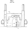
- Figure 1 is a sectional elevation of known apparatus 10 for maintaining a relatively low proportion of coating on the finish region 15 of bottle 13 .
- a process stream 12 under pressure from supply blower 28 impinges upon bottle 13 , the temperature of the surface of which is of the order of from about 350 to about 400 degrees Celsius; generally, bottle 13 , moving toward the observer in a direction perpendicular to the plane of the drawing, has recently emerged from a forming machine, not shown.
- Deflection stream 14 flowing substantially in the same direction as process stream 12 , is intended to keep stream 12 from depositing an undesirably thick coating of material on the finish 15 of bottle 13 .
- Recirculation blower 16 maintains a low pressure within plenum 17 to cause process stream 12 to move onto and around bottle 13 , thereby causing the coating precursor to react with the hot surface of the glass substrate.
- process stream 12 is generally a mixture of glass-coating precursors such as, e.g., a volatile or finely dispersed tin or titanium compound in a carrier fluid such as, e.g., air or the like.
- a carrier fluid such as, e.g., air or the like.
- Compounds which are useful with the apparatus of the present invention include those which are capable of reaction with air or other process-stream oxidizing moiety on the surface of the substrate to form a metal oxide, and comprise conveniently but not by way of limitation, materials such as organotin compounds generally, monobutyltin trichloride, tin tetrachloride, titanium tetrachloride and tetraisopropyl titanate.
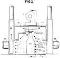
- blower 19 delivers air or other fluid through plenum 22 and diffuser plate 23 as vertical deflection stream 18 onto the finish region 15 of bottles 13 .
- Diffuser plate 23 contains a plurality of holes, and is designed to moderate the force of process fluid supplied by blower 19 .
- Figure 3 is a section taken along lines 3 - 3 of Figure 2.
- Bottles 13 are shown moving on conveyor 11 in the direction marked by the arrow A .
- standing waves represented vectorially by arrows 26 and 27 would develop in plenum 22 , producing differences in pressure along its length.
- the velocity of vertical deflection stream 18 would vary from point to point throughout the coating apparatus, making precise control of that stream extremely difficult.
- apparatus comprising relocated blower 29 which delivers process air or other suitable fluid 41 into an end, as opposed to between the ends, of upper plenum chamber 32 ; the air passes first through attenuator 34 plate into plenum lower chamber 36 , and then through diffuser plate 38 to provide a substantially uniform stream of process air 41 into the finish region of bottles 13 .
- Clean-out door 42 provides access to the interior of plenum upper chamber 32 and plenum lower chamber 36 for removing, replacing or servicing attenuator plate 34 and diffuser plate 38 as may be appropriate or necessary.
- Attenuator 34 It has been found preferable to position attenuator 34 substantially at an angle to the flow of process fluid as shown in Figure 3; it is our understanding of the operation of this apparatus that the fluid, in passing through attenuator 34 , is redirected to a plurality of small, low-energy jets 45 without the generation of substantial turbulence or formation of standing waves, and the subsequent passage of that fluid through lower diffuser plate 38 is quite uniform.
- Throttle means 49 in Figure 4 such as, e.g., an iris valve, but chosen to avoid introducing turbulence into fluid stream 41 , permits an additional method of controlling the force and velocity of stream 41 , and therefore the force and velocity of jets 45 .
- a similar or conjunctive control can be achieved by regulating the force of blower 29 by means not shown, but well known to those skilled in the art.
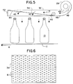
- FIG. 5 shows another embodiment of the apparatus of the present invention, where attenuator plate 34 is juxtaposed against an auxiliary or supplementary attenuator plate 44 ; by this juxtaposition, any clogging of the passages in the attenuator plates can be easily remedied by opening clean-out 42 and replacing the attenuators, or by moving one past the other, thus causing mechanical friction to dislodge accumulated particles such as atmospheric dust or partially reacted or hydrolyzed coating compound.
- attenuators 34 and 44 can be mounted in a fashion which would permit their substantially frequent or constant movement relative to each other, in order to maintain clean holes without the need for exterior manipulation.
- Such apparatus 46 can comprise, e.g., a motor having an eccentrically-mounted weight which would cause a low-amplitude vibration in attenuator 34 , by direct attachment 46 to that attenuator, or any other motive means for inducing relative movement, well known to those skilled in the art.
- the attenuators are of complementary shape, and juxtaposed closely enough to permit particulate removal by moving either attenuator with respect to the other.
- filtration means can be supplied to remove particulate and other deleterious matter from the input fluid stream prior to that fluid being urged into or through plenum upper chamber 32 .
- Figure 6 is a plan view of attenuator plate 34 , having a plurality of holes 61 therein, to permit the passage of process fluid, while moderating its velocity and changing its direction by up to 90°, in a plurality of low-energy jets 45 .
- Attenuator 44 is substantially similar in design, and those skilled in the art will realize that that the shape of the holes 61 is not critical to the operation of the present invention, it being a sufficient condition that the size of the holes 61 be adequate to permit the passage of air, and that their spacing be chosen to prevent the development of extraneous currents between the individual jets 45 .
Landscapes
- Chemical & Material Sciences (AREA)
- General Chemical & Material Sciences (AREA)
- Chemical Kinetics & Catalysis (AREA)
- Engineering & Computer Science (AREA)
- Materials Engineering (AREA)
- Organic Chemistry (AREA)
- Metallurgy (AREA)
- Mechanical Engineering (AREA)
- Life Sciences & Earth Sciences (AREA)
- Geochemistry & Mineralogy (AREA)
- Surface Treatment Of Glass (AREA)
- Application Of Or Painting With Fluid Materials (AREA)
- Details Of Rigid Or Semi-Rigid Containers (AREA)
- Surface Treatment Of Glass Fibres Or Filaments (AREA)
- Nozzles (AREA)
Abstract
Description
- This invention is in the field of methods and apparatus for the application of coatings to glass containers. In some embodiments, the invention is in the field of methods and devices for the application of coatings of varying thicknesses to bottles, jars and the like, particularly where the distance between a closure region and a shoulder of the container is minimal.
- The utility of glass bottles and jars has been broadened by surface coating to decrease abrasion and breakage, as taught by Carl, et al., U.S. 3,323,889; Gatchet, et al., U.S. 3,516,811; Scholes, et al., U.S. 3,819,404; Hofmann, et al., U.S. 4,431,692; Lindner, et al., U.S. 4,389,234 and 4,668,268; and others. Gatchet observed the utility of avoiding all coating on the closure region of the container, known in the art as the "finish", by maintaining the finish region out of contact with the treatment gas. Several of the prior workers in this field have recognized the existence of non-linear currents in the coating-precursor stream, including omnidirectional turbulent currents and upwardly-moving convection currents.
- It is known in the art of glass manufacture that uncoated glass is generally unsuitable for handling in high-speed operations, its brittleness rendering the surface susceptible to potentially catastrophic damage. Specifically, bottles and other glass containers made in large numbers are susceptible to breakage in the course of being transferred through various manufacturing steps, or during a subsequent filling operation.
- In order to minimize the problems thus encountered, a number of treatments have been applied to the containers as they are manufactured. Such treatments include, e.g., spraying with lubricant such as a wax or fatty acid, and applying reactive coatings by chemical-vapor-deposition (CVD) or spray-pyrolysis methods.
- Treatment by CVD typically can involve propelling a vapor of metal-containing species onto the hot glass-container surface to produce a thin layer of metal oxide, typically stannic or titanic oxide, which can anchor a waxy lubricant added after annealing. Without the metal-oxide layer, such waxy lubricants do not adhere well to glass under the conditions encountered in a filling line.
- In our U.S. 4,668,268, Lindner et al. teach the application of a metal-containing compound, generally an organotin material, to the surface of a glass container immediately after that container has acquired sufficient mechanical integrity to maintain its shape on a material-handling line. The US 4,668,268 disclosure describes a coating hood for applying a uniform protective coating to a glass container as the container is transported by material-handling means, generally a conveyor belt, after its formation from molten glass. The described coating hood comprises a pair of side walls with a coating jet in at least one of the walls, and an exhaust system to remove the process stream from the coating zone.
- In the field relating to the coating of containers generally, and notably of glass bottles, one problem which is repeatedly encountered is that of applying adequate material to the body of the container while keeping the finish region of the container untreated. It is desirable to maintain the finish portion relatively free of coating material for both chemical and physical reasons. Where a tin compound is deposited on the screw threads of, for instance, a jar for holding baby food, the chemical, electrochemical or mechanical interaction between the metal cap and the coating may be sufficient to discolor the glass or to corrode the metal. Another disadvantage of coating on the finish is the possible effect on the frictional interaction between the glass and the cap or other closure; low friction can permit leakage, while too high a frictional value can impede both placement and removal of the closure. In either case, the utility of the treated container is adversely affected.
- In the art of coating glass containers, the film deposited onto the glass surface is measured in arbitrary coating thickness units (CTU), the unit thickness being about 2.5 Angstroms (Å); metal-oxide coatings of from about 30 to 40 CTU, or about 60 to 100 Å, may be required for the body of the container, while acceptable coating on the finish may be one-half or even one-tenth of this amount, depending upon the ware and its intended use. While manufacturers of baby food state a preference for a finish-coating thickness of less than half that of the shoulder coating, proximity of finish to shoulder has heretofore made the desired separation difficult or impossible to achieve.
- The improvement in the art which US-A-4668268 provided in partial response to the problem of differential wall and finish thickness was accomplished by directing a stream of air in which no coating material was entrained onto the finish in order to displace and dilute coating material which would otherwise coat the finish region almost as much as the shoulder or the body of the container. By selection of the geometry of the coating hood as a function of the containers to be coated, this technique was able to effect acceptable coating thickness on the sidewalls, concomitant with protection of the finish for the large volume of glass containers having necks of appreciable length, such containers comprising beer, wine and soft-drink bottles and the like.
- However, while the utility of the apparatus of US-A-4668268 is excellent for beer, wine and other bottles with relatively long necks, it is only marginal for applications such as food and cosmetic bottles and jars having very short or non-existent necks, i.e., where the finish region is juxtaposed adjacent the body. The latter group comprises, e.g., jam, jelly and cold-cream jars, and containers for baby foods, peanut butter, thixotropic salad dressings and the like. For the purposes of this specification, the terms "bottle" and "jar" may be used with substantial interchangeability, although generally, a jar has a relatively small separation of body and finish, while a bottle has a substantially larger separation.
- While the most effective prior art directs the vapor-laden air stream horizontally at the label panel of the ware, and a stream of vapor-free air at the finish region, some of the coating stream has been found inevitably to be displaced toward the finish by conditions within the coating hood. Displacement can originate in, e.g., the shearing interaction between adjacent coating streams traversing the hood in opposite directions; in the turbulence caused by the ware as it crosses the coating streams; in the strong convection currents caused by hot ware moving through a coating stream that is typically hundreds of degrees cooler than the ware; and in the induced draft caused by the finish-protection stream. Further, even the best of the prior art devices tend to require careful attention in order to maintain adjustment of the parameters required for an acceptable differential between the body or shoulder and the finish region.
- Some aspects and preferred aspects of the invention are set out in the claims.
- In one general aspect, the invention provides apparatus for the chemical coating of glass articles, particularly containers, comprising a conveyor path along which the articles are conveyed for treatment, means for directing a coating flow containing coating precursor compound against the articles from one or both sides of the conveyor path, means for exhausting and/or recirculating spent coating supply from the conveyor path, and means for inhibiting coating of an upper portion of the articles, characterised in that the means for inhibiting such coating comprise a blower for blowing a non-coating flow down onto the articles from above the conveyor path, by way of an accumulating plenum and an attenuator for distributing the non-coating flow.
- The non-coating flow is desirably vertically, or substantially vertically, downward.
- The non-coating flow desirably enters the conveyor path area through a downwardly-facing ceiling thereof. The non-coating downward flow is desirably applied all along a treatment zone of the conveyor path at which the coating supply is being applied.
- A preferred form of attenuator is a foraminous plate, usually a flat plate. The distribution of holes therein should be regular, and preferably symmetrical with respect to the articles on the conveyor path.
- To achieve a uniform downward flow, it is particularly preferred that the non-coating blower blows the non-coating supply into the plenum in a direction which is not the downward direction. Most preferably, it is blown in in a generally horizontal direction and then redirected within or by the plenum. For this purpose, an attenuator layer may be positioned within the plenum at an angle between horizontal and vertical, preferably an acute angle to the horizontal. The angle attenuator is desirably symmetrical to the conveyor path axis, i.e. angled up along rather than across that axis.
- Means may be provided for mechanically agitating the attenuator, to inhibit the accumulation of deposits thereon.
- In another aspect, the invention provides methods of coating treatment of glass articles, particularly glass containers, in which the articles are moved along a conveyor path, a coating supply containing a coating precursor compound is blown on the articles from at least one side, and a finish-coating inhibition flow is blown down on them from above by way of an accumulating plenum and an attenuator.
- In the method, features of the plenum and attenuator may be as specified above.
- In another aspect we provide apparatus for the coating of glass containers (e.g. having a small neck region) where the apparatus comprises a coating hood with a high-pressure portion and a juxtaposed low-pressure portion having a center section for the introduction of air without coating precursor, and is an improvement which comprises a center section for the non-turbulent introduction of process fluid free of coating precursor, and traveling essentially perpendicular to the coating stream. The invention further includes the article made by the apparatus.
- One embodiment of the present invention is an improved apparatus for the application of glass-coating material to a glass container having a minimal separation between the body of the container and the top portion, the apparatus comprising coating-supply means, exhaust or recirculation means, a plurality of side walls with a coating jet in at least one of the walls, and an exhaust system to remove the process stream from the coating zone, wherein the improvement comprises fluid-stream-directing means juxtaposed above the container, the stream-directing means having at least a plenum and one attenuating plate, wherein the fluid within the plenum has minimal turbulence.
- In preferred apparatus for the direction of a process-fluid supply, generally air, perpendicularly across the stream of coating material, the process fluid is provided by pressurizing means to a plenum; an attenuator, mounted at an angle to the principal direction of flow of the fluid, distributes the process air evenly, to avoid turbulence, standing waves and regions of high or low air velocity.
- In the drawings;
- Figure 1 is an elevation of apparatus of the prior art.
- Figure 2 is an elevation showing an initial concept of the invention.
- Figure 3 is a section taken along lines 3-3 of Figure 2.
- Figure 4 shows a sectional view of an embodiment of the invention.
- Figure 5 is another embodiment.
- Figure 6 is a plan view of an attenuator plate shown in Figures 4 and 5.
- Figure 1 is a sectional elevation of known
apparatus 10 for maintaining a relatively low proportion of coating on thefinish region 15 ofbottle 13. Briefly described, aprocess stream 12 under pressure fromsupply blower 28 impinges uponbottle 13, the temperature of the surface of which is of the order of from about 350 to about 400 degrees Celsius; generally,bottle 13, moving toward the observer in a direction perpendicular to the plane of the drawing, has recently emerged from a forming machine, not shown.Deflection stream 14, flowing substantially in the same direction asprocess stream 12, is intended to keepstream 12 from depositing an undesirably thick coating of material on thefinish 15 ofbottle 13.Recirculation blower 16 maintains a low pressure withinplenum 17 to causeprocess stream 12 to move onto and aroundbottle 13, thereby causing the coating precursor to react with the hot surface of the glass substrate. Other portions of this typical apparatus not germane to this invention are not further described here, being well within the understanding of one skilled in the art. - In the operation of the depicted coating-
hood apparatus 10,process stream 12 is generally a mixture of glass-coating precursors such as, e.g., a volatile or finely dispersed tin or titanium compound in a carrier fluid such as, e.g., air or the like. Compounds which are useful with the apparatus of the present invention include those which are capable of reaction with air or other process-stream oxidizing moiety on the surface of the substrate to form a metal oxide, and comprise conveniently but not by way of limitation, materials such as organotin compounds generally, monobutyltin trichloride, tin tetrachloride, titanium tetrachloride and tetraisopropyl titanate. - Upon impinging on
bottle 13, the organotin is converted to tin oxide as a coating on the glass surface. Volatile products and unreacted chemicals are recirculated by the action ofblower 16. While theprocess stream 12 has a tendency toward turbulence on encounteringbottle 13,deflection stream 14 maintains a zone which is more, but not completely, free of the coating precursor carried instream 12. As a result coatings secured by the prior-art apparatus provide a gradient of coating with a thickness of the order of 100 Å on the body of the container to about 10 Å in the finish region. However, in field application, it has not been possible to steepen the gradient, that is, to provide either more coating on the body or less on the finish, nor to apply the process of the apparatus in a consistently successful fashion to containers with necks shorter than about 25 millimeters. - We have discovered that by providing a substantially vertical stream of process fluid, generally air, directed in a fashion perpendicular to the coating stream, it is possible to keep the deposition of material on the finish to a very low level. However, a simple approach as shown in Figure 2 tended to produce variable results, limiting the utility of the idea to long-necked ware such as, e.g., beer and wine bottles and the like. In Figure 2,
blower 19 delivers air or other fluid throughplenum 22 anddiffuser plate 23 asvertical deflection stream 18 onto thefinish region 15 ofbottles 13.Diffuser plate 23 contains a plurality of holes, and is designed to moderate the force of process fluid supplied byblower 19. In attempting to regulate the passage of air fromplenum 22 throughdiffuser plate 23 into the treating zone, however, we discovered that the system caused the formation of standing waves and pressure nodes, causing the velocity of theprotective stream 18 to vary along the length of the delivery apparatus. The nature of the problem is illustrated more fully in Figure 3. - Figure 3 is a section taken along lines 3 - 3 of Figure 2.
Bottles 13 are shown moving on conveyor 11 in the direction marked by the arrow A. Depending on the size and geometry ofplenum 22 and the velocity ofprocess fluid 21 delivered byblower 19, standing waves represented vectorially byarrows plenum 22, producing differences in pressure along its length. As a result of the difference in pressure, the velocity ofvertical deflection stream 18 would vary from point to point throughout the coating apparatus, making precise control of that stream extremely difficult. - In Figure 4, apparatus is shown comprising relocated
blower 29 which delivers process air or othersuitable fluid 41 into an end, as opposed to between the ends, ofupper plenum chamber 32; the air passes first throughattenuator 34 plate into plenumlower chamber 36, and then throughdiffuser plate 38 to provide a substantially uniform stream ofprocess air 41 into the finish region ofbottles 13. Clean-outdoor 42 provides access to the interior of plenumupper chamber 32 and plenumlower chamber 36 for removing, replacing or servicingattenuator plate 34 anddiffuser plate 38 as may be appropriate or necessary. It has been found preferable to positionattenuator 34 substantially at an angle to the flow of process fluid as shown in Figure 3; it is our understanding of the operation of this apparatus that the fluid, in passing throughattenuator 34, is redirected to a plurality of small, low-energy jets 45 without the generation of substantial turbulence or formation of standing waves, and the subsequent passage of that fluid throughlower diffuser plate 38 is quite uniform. - With the availability of a uniform stream of non-turbulent process fluid, it becomes easier to adjust the flow rate of that stream with sufficient precision to maintain a zone free of coating material in the finish region without either starving the shoulder or body region of the ware being coated, or permitting the stream of coating material to rise into the finish region That adjustment is represented by the
uniform vector arrows 37 in Figure 4. In the fashion described, the finish can be kept virtually free of coating, while the contact areas of the ware are provided with adequate coating. With apparatus as described, we have been able to provide a uniform coating thickness of about 50Å on the body of a bottle, while the finish region was substantially uncoated. - Throttle means 49 in Figure 4, such as, e.g., an iris valve, but chosen to avoid introducing turbulence into
fluid stream 41, permits an additional method of controlling the force and velocity ofstream 41, and therefore the force and velocity ofjets 45. A similar or conjunctive control can be achieved by regulating the force ofblower 29 by means not shown, but well known to those skilled in the art. - Figure 5 shows another embodiment of the apparatus of the present invention, where
attenuator plate 34 is juxtaposed against an auxiliary orsupplementary attenuator plate 44; by this juxtaposition, any clogging of the passages in the attenuator plates can be easily remedied by opening clean-out 42 and replacing the attenuators, or by moving one past the other, thus causing mechanical friction to dislodge accumulated particles such as atmospheric dust or partially reacted or hydrolyzed coating compound. In the alternative,attenuators attenuator 34, by direct attachment 46 to that attenuator, or any other motive means for inducing relative movement, well known to those skilled in the art. - It is sufficient if the attenuators are of complementary shape, and juxtaposed closely enough to permit particulate removal by moving either attenuator with respect to the other. Further, filtration means, not shown but well known to those skilled in the art, can be supplied to remove particulate and other deleterious matter from the input fluid stream prior to that fluid being urged into or through plenum
upper chamber 32. - Figure 6 is a plan view of
attenuator plate 34, having a plurality ofholes 61 therein, to permit the passage of process fluid, while moderating its velocity and changing its direction by up to 90°, in a plurality of low-energy jets 45.Attenuator 44 is substantially similar in design, and those skilled in the art will realize that that the shape of theholes 61 is not critical to the operation of the present invention, it being a sufficient condition that the size of theholes 61 be adequate to permit the passage of air, and that their spacing be chosen to prevent the development of extraneous currents between theindividual jets 45. - By the use of the coating apparatus embodying these concepts, it has been found possible to establish parameters for coating-stream flow, exhaust velocity and bottle travel rate, and then to set the volume and velocity of the vertical finish-protection stream to provide small or even substantially zero thickness of coating on the finish; thereafter, further adjustments to maintain the system in balance we found to be virtually unnecessary.
- Modifications and improvements to the preferred forms of the invention disclosed and described herein may occur to those skilled in the art who come to understand the principles and precepts hereof. Accordingly, the scope of the patent to be issued hereon should not be limited solely to the embodiments of the invention set forth herein.
Claims (25)
- Apparatus for the application of glass-coating material to a glass container,
the apparatus comprising coating-precursor supply means, exhaust or recirculation means, a plurality of side walls with a coating jet in at least one of the walls, means for providing finish protection, and an exhaust system to remove the process stream from the coating zone, characterized by fluid-stream-directing means juxtaposed above the container, the fluid-stream-directing means having at least a plenum and at least one attenuator. - The apparatus of claim 1 having a plurality of attenuators.
- The apparatus of claim 1 having a plurality of juxtaposed attenuators.
- The apparatus of claim 1 having a plurality of juxtaposed attenuators, at least one attenuator being affixed to motive means.
- The apparatus of claim 1 having at least one clean-out means.
- The apparatus of claim 2 wherein the attenuator is mounted at an angle.
- The apparatus of claim 1 wherein the means for finish protection comprises a blower.
- The apparatus of claim 1 further including throttle means.
- The apparatus of claim 1 wherein the means for finish protection comprises a blower and an attenuator mounted at an angle within the plenum.
- The apparatus of claim 8 wherein the means for finish protection comprises a blower delivering a process fluid into an end of the plenum.
- The apparatus of claim 8 having an upper plenum chamber and a lower plenum chamber.
- A method of applying a minimal coating to the finish of a glass container while applying a coating of acceptable thickness to the body of the container which consists of applying a coating precursor to the body of the container in apparatus comprising coating-precursor supply means, exhaust or recirculation means, a plurality of side walls with a coating jet in at least one of the walls, means for providing finish protection, and an exhaust system to remove the process stream from the coating zone, characterized by fluid-stream-directing means juxtaposed above the container, the fluid-stream-directing means having at least a plenum and at least one attenuator.
- The method of claim 12 wherein the apparatus has exhaust means intermediate the finish and the shoulder.
- The method of claim 12 having a plurality of attenuators.
- The method of claim 12 having a plurality of juxtaposed attenuators.
- The method of claim 12 having a plurality of juxtaposed attenuators, at least one attenuator being affixed to motive means.
- The method of claim 12 having at least one clean-out means.
- The method of claim 12 having inlet-filter means.
- The method of claim 12 wherein the attenuator is mounted at an angle.
- The method of claim 12 wherein the means for finish protection comprises a blower.
- The method of claim 12 wherein the means for finish protection comprises a blower and an attenuator mounted at an angle within the plenum.
- The method of claim 21 wherein the means for finish protection comprises a blower delivering a process fluid into an end of the plenum.
- The method of claim 21 having an upper plenum chamber and a lower plenum chamber.
- A glass bottle having a finish region juxtaposed adjacent a body, the body having a coating thickness of not less than about 50Å, the finish region being substantially uncoated, wherein the coating is applied by apparatus comprising coating-supply means, exhaust or recirculation means, a plurality of side walls with a coating jet in at least one of the walls, and an exhaust system to remove the process stream from the coating zone, characterized by fluid-stream-directing means juxtaposed above the container, the fluid-stream-directing means having at least a plenum and at least one attenuator.
- The bottle of claim 24, wherein the bottle is a wide-mouth jar having substantially no neck between the finish and the body, wherein the coating on the finish is less than one-half the coating on the body.
Applications Claiming Priority (2)
| Application Number | Priority Date | Filing Date | Title |
|---|---|---|---|
| US71850191A | 1991-06-20 | 1991-06-20 | |
| US718501 | 1991-06-20 |
Publications (2)
| Publication Number | Publication Date |
|---|---|
| EP0519597A1 true EP0519597A1 (en) | 1992-12-23 |
| EP0519597B1 EP0519597B1 (en) | 1996-10-16 |
Family
ID=24886306
Family Applications (1)
| Application Number | Title | Priority Date | Filing Date |
|---|---|---|---|
| EP92304271A Expired - Lifetime EP0519597B1 (en) | 1991-06-20 | 1992-05-12 | Glass-coating apparatus and methods |
Country Status (9)
| Country | Link |
|---|---|
| US (1) | US5584903A (en) |
| EP (1) | EP0519597B1 (en) |
| JP (1) | JP2975214B2 (en) |
| AT (1) | ATE144232T1 (en) |
| CA (1) | CA2068100C (en) |
| DE (1) | DE69214528T2 (en) |
| DK (1) | DK0519597T3 (en) |
| ES (1) | ES2095403T3 (en) |
| GR (1) | GR3021948T3 (en) |
Cited By (4)
| Publication number | Priority date | Publication date | Assignee | Title |
|---|---|---|---|---|
| GB2486703A (en) * | 2010-12-23 | 2012-06-27 | Spraybooth Technology Ltd | Spray booth ventilation system with nozzles for blowing air transverse the main airflow |
| WO2017115086A1 (en) * | 2015-12-31 | 2017-07-06 | Pilkington Group Limited | High strength glass containers |
| WO2017115087A1 (en) * | 2015-12-31 | 2017-07-06 | Pilkington Group Limited | High strength glass containers |
| US12584224B2 (en) | 2015-07-29 | 2026-03-24 | Pilkington Group Limited | Coating apparatus |
Families Citing this family (11)
| Publication number | Priority date | Publication date | Assignee | Title |
|---|---|---|---|---|
| DE69824357T2 (en) * | 1997-09-24 | 2005-06-16 | Kirin Beer K.K. | Method and device for producing and coating bottles |
| AUPQ130299A0 (en) * | 1999-06-30 | 1999-07-22 | Organotin Chemie Gmbh | Apparatus and method for coating glass containers |
| NL1016930C2 (en) * | 2000-12-20 | 2002-06-21 | Atofina Vlissingen B V | Device for applying a coating to glass containers. |
| US6918067B2 (en) * | 2002-04-30 | 2005-07-12 | International Business Machines Corporation | Detecting network instability |
| KR101146982B1 (en) * | 2009-11-20 | 2012-05-22 | 삼성모바일디스플레이주식회사 | Aapparatus for thin layer deposition and method of manufacturing organic light emitting display apparatus |
| US20130334089A1 (en) * | 2012-06-15 | 2013-12-19 | Michael P. Remington, Jr. | Glass Container Insulative Coating |
| CN108290174B (en) * | 2015-11-24 | 2021-04-06 | 阿科玛股份有限公司 | Interchangeable center section of a glass-coated cover |
| RU2018141754A (en) | 2016-05-12 | 2020-06-15 | Анхойзер-Буш Инбев С.А. | GLASS TUBES HAVING AN IMAGE PERFORMED BY INKJET PRINT AND METHOD FOR PRODUCING IT |
| US11117154B2 (en) | 2017-03-31 | 2021-09-14 | Arkema Inc. | Modular hood for coating glass containers |
| US11131017B2 (en) | 2018-08-17 | 2021-09-28 | Owens-Brockway Glass Container Inc. | Vaporized metal application hood |
| US20250270134A1 (en) * | 2024-02-23 | 2025-08-28 | Owens-Brockway Glass Container Inc. | Cold-end coating for a glass container |
Citations (5)
| Publication number | Priority date | Publication date | Assignee | Title |
|---|---|---|---|---|
| EP0099480A1 (en) * | 1982-07-17 | 1984-02-01 | RUHRGLAS GmbH | Process and treatment chamber for the coating of glass containers with titanium oxide |
| EP0187515A1 (en) * | 1984-12-20 | 1986-07-16 | M & T Chemicals, Inc. | Hood for coating glass containers and coating method |
| US4615916A (en) * | 1984-06-25 | 1986-10-07 | Owens-Illinois, Inc. | Surface treatment of glass containers |
| EP0425307A1 (en) * | 1989-10-27 | 1991-05-02 | Elf Atochem North America, Inc. | Method and apparatus for controlled-profile coating of containers |
| US5081953A (en) * | 1989-10-27 | 1992-01-21 | Atochem North America, Inc. | Center section for coating hood for glass containers |
Family Cites Families (10)
| Publication number | Priority date | Publication date | Assignee | Title |
|---|---|---|---|---|
| US3323889A (en) * | 1963-04-16 | 1967-06-06 | Owens Illinois Inc | Method for increasing scratch resistance of a glass surface with a pyrolyzing treatment and a coating of an olefin polymer |
| US3516811A (en) * | 1966-10-04 | 1970-06-23 | Indian Head Inc | Method of and apparatus for coating glassware retaining its heat of formation |
| US3561940A (en) * | 1967-10-02 | 1971-02-09 | Ball Corp | Method and apparatus for preparing glass articles |
| US3688737A (en) * | 1969-11-04 | 1972-09-05 | Glass Container Mfg Inst Inc | Vapor deposition apparatus including air mask |
| US3690289A (en) * | 1971-07-22 | 1972-09-12 | Charles A Frank | Vapor treatment hood |
| US3819404A (en) * | 1972-04-04 | 1974-06-25 | Ball Corp | Method for treating vitreous surfaces |
| US4220118A (en) * | 1978-08-15 | 1980-09-02 | Domglas Inc. | Spray hood |
| US4431692A (en) * | 1980-02-15 | 1984-02-14 | Owens-Illinois, Inc. | Process for making glass surfaces abrasion-resistant and article produced thereby |
| US4389234A (en) * | 1982-03-18 | 1983-06-21 | M&T Chemicals Inc. | Glass coating hood and method of spray coating glassware |
| US4879970A (en) * | 1987-04-21 | 1989-11-14 | M&T Chemicals Inc. | Coating hood for applying coating compound on containers |
-
1992
- 1992-05-06 CA CA002068100A patent/CA2068100C/en not_active Expired - Fee Related
- 1992-05-12 AT AT92304271T patent/ATE144232T1/en not_active IP Right Cessation
- 1992-05-12 DK DK92304271.7T patent/DK0519597T3/en active
- 1992-05-12 DE DE69214528T patent/DE69214528T2/en not_active Expired - Fee Related
- 1992-05-12 ES ES92304271T patent/ES2095403T3/en not_active Expired - Lifetime
- 1992-05-12 EP EP92304271A patent/EP0519597B1/en not_active Expired - Lifetime
- 1992-05-21 JP JP4153011A patent/JP2975214B2/en not_active Expired - Fee Related
-
1994
- 1994-02-18 US US08/203,053 patent/US5584903A/en not_active Expired - Lifetime
-
1996
- 1996-12-10 GR GR960403365T patent/GR3021948T3/en unknown
Patent Citations (5)
| Publication number | Priority date | Publication date | Assignee | Title |
|---|---|---|---|---|
| EP0099480A1 (en) * | 1982-07-17 | 1984-02-01 | RUHRGLAS GmbH | Process and treatment chamber for the coating of glass containers with titanium oxide |
| US4615916A (en) * | 1984-06-25 | 1986-10-07 | Owens-Illinois, Inc. | Surface treatment of glass containers |
| EP0187515A1 (en) * | 1984-12-20 | 1986-07-16 | M & T Chemicals, Inc. | Hood for coating glass containers and coating method |
| EP0425307A1 (en) * | 1989-10-27 | 1991-05-02 | Elf Atochem North America, Inc. | Method and apparatus for controlled-profile coating of containers |
| US5081953A (en) * | 1989-10-27 | 1992-01-21 | Atochem North America, Inc. | Center section for coating hood for glass containers |
Cited By (9)
| Publication number | Priority date | Publication date | Assignee | Title |
|---|---|---|---|---|
| GB2486703A (en) * | 2010-12-23 | 2012-06-27 | Spraybooth Technology Ltd | Spray booth ventilation system with nozzles for blowing air transverse the main airflow |
| GB2486703B (en) * | 2010-12-23 | 2013-04-10 | Spraybooth Technology Ltd | Spray booths |
| US12584224B2 (en) | 2015-07-29 | 2026-03-24 | Pilkington Group Limited | Coating apparatus |
| WO2017115086A1 (en) * | 2015-12-31 | 2017-07-06 | Pilkington Group Limited | High strength glass containers |
| WO2017115087A1 (en) * | 2015-12-31 | 2017-07-06 | Pilkington Group Limited | High strength glass containers |
| CN108430942A (en) * | 2015-12-31 | 2018-08-21 | 皮尔金顿集团有限公司 | high strength glass container |
| CN108430943A (en) * | 2015-12-31 | 2018-08-21 | 皮尔金顿集团有限公司 | high strength glass container |
| AU2016381218B2 (en) * | 2015-12-31 | 2020-11-05 | Pilkington Group Limited | High strength glass containers |
| US10927037B2 (en) | 2015-12-31 | 2021-02-23 | Pilkington Group Limited | Method of increasing the resistance to internal pressure of a glass container |
Also Published As
| Publication number | Publication date |
|---|---|
| JP2975214B2 (en) | 1999-11-10 |
| CA2068100A1 (en) | 1992-12-21 |
| EP0519597B1 (en) | 1996-10-16 |
| GR3021948T3 (en) | 1997-03-31 |
| ATE144232T1 (en) | 1996-11-15 |
| JPH05193990A (en) | 1993-08-03 |
| CA2068100C (en) | 2000-07-18 |
| US5584903A (en) | 1996-12-17 |
| DE69214528D1 (en) | 1996-11-21 |
| ES2095403T3 (en) | 1997-02-16 |
| DE69214528T2 (en) | 1997-03-06 |
| DK0519597T3 (en) | 1997-03-24 |
Similar Documents
| Publication | Publication Date | Title |
|---|---|---|
| EP0519597B1 (en) | Glass-coating apparatus and methods | |
| JP3228768B2 (en) | Apparatus for depositing metal oxide coatings on glass articles | |
| US4431692A (en) | Process for making glass surfaces abrasion-resistant and article produced thereby | |
| US4562095A (en) | Method and apparatus for manufacturing a uniformly coated substrate | |
| US4917717A (en) | Apparatus for and process of coating glass | |
| US8541055B2 (en) | Reflective coatings for glass articles, methods of deposition, and articles made thereby | |
| DK154823B (en) | PROCEDURE FOR CREATING A TINOXIDE COATING ON A SURFACE OF A GLASS SUBSTRATE OR ON A PREVIOUSLY CREATED COATING | |
| US4933211A (en) | Process and device for coating a substrate with a pulverulent product | |
| US5136976A (en) | Method and means for controlled-profile coating of glass containers | |
| JPS595021B2 (en) | Uniform dispersion device for powder materials | |
| US3952118A (en) | Method for hot-end coating of glass containers | |
| US4425868A (en) | Coating hood | |
| USRE28076E (en) | Vapor deposition apparatus including air mask | |
| US3684469A (en) | Method of coating glassware | |
| US4880698A (en) | Coated flat glass | |
| CA1172918A (en) | Process for making glass surfaces abrasion-resistant and article produced thereby | |
| US3690289A (en) | Vapor treatment hood | |
| WO1996033955A1 (en) | Method and apparatus for applying a layer to bottles | |
| US4555416A (en) | Spray apparatus with self cleaning nozzle | |
| US3920433A (en) | Apparatus and method for improved glassware coating | |
| CN108026641B (en) | coating equipment |
Legal Events
| Date | Code | Title | Description |
|---|---|---|---|
| PUAI | Public reference made under article 153(3) epc to a published international application that has entered the european phase |
Free format text: ORIGINAL CODE: 0009012 |
|
| AK | Designated contracting states |
Kind code of ref document: A1 Designated state(s): AT BE CH DE DK ES FR GB GR IT LI LU MC NL PT SE |
|
| 17P | Request for examination filed |
Effective date: 19930219 |
|
| 17Q | First examination report despatched |
Effective date: 19950109 |
|
| RAP1 | Party data changed (applicant data changed or rights of an application transferred) |
Owner name: ELF ATOCHEM NORTH AMERICA, INC. |
|
| RAP3 | Party data changed (applicant data changed or rights of an application transferred) |
Owner name: ELF ATOCHEM NORTH AMERICA, INC. |
|
| GRAG | Despatch of communication of intention to grant |
Free format text: ORIGINAL CODE: EPIDOS AGRA |
|
| GRAH | Despatch of communication of intention to grant a patent |
Free format text: ORIGINAL CODE: EPIDOS IGRA |
|
| GRAH | Despatch of communication of intention to grant a patent |
Free format text: ORIGINAL CODE: EPIDOS IGRA |
|
| GRAA | (expected) grant |
Free format text: ORIGINAL CODE: 0009210 |
|
| AK | Designated contracting states |
Kind code of ref document: B1 Designated state(s): AT BE CH DE DK ES FR GB GR IT LI LU MC NL PT SE |
|
| REF | Corresponds to: |
Ref document number: 144232 Country of ref document: AT Date of ref document: 19961115 Kind code of ref document: T |
|
| ITF | It: translation for a ep patent filed | ||
| REF | Corresponds to: |
Ref document number: 69214528 Country of ref document: DE Date of ref document: 19961121 |
|
| ET | Fr: translation filed | ||
| REG | Reference to a national code |
Ref country code: CH Ref legal event code: NV Representative=s name: E. BLUM & CO. PATENTANWAELTE |
|
| REG | Reference to a national code |
Ref country code: ES Ref legal event code: FG2A Ref document number: 2095403 Country of ref document: ES Kind code of ref document: T3 |
|
| REG | Reference to a national code |
Ref country code: GR Ref legal event code: FG4A Free format text: 3021948 |
|
| REG | Reference to a national code |
Ref country code: DK Ref legal event code: T3 |
|
| PLBE | No opposition filed within time limit |
Free format text: ORIGINAL CODE: 0009261 |
|
| STAA | Information on the status of an ep patent application or granted ep patent |
Free format text: STATUS: NO OPPOSITION FILED WITHIN TIME LIMIT |
|
| 26N | No opposition filed | ||
| REG | Reference to a national code |
Ref country code: CH Ref legal event code: PFA Free format text: ELF ATOCHEM NORTH AMERICA, INC. TRANSFER- ATOFINA CHEMICALS, INC. |
|
| REG | Reference to a national code |
Ref country code: PT Ref legal event code: PD4A Free format text: ATOFINA CHEMICALS, INC US Effective date: 20000908 |
|
| REG | Reference to a national code |
Ref country code: FR Ref legal event code: CD Ref country code: FR Ref legal event code: CA |
|
| REG | Reference to a national code |
Ref country code: GB Ref legal event code: IF02 |
|
| PGFP | Annual fee paid to national office [announced via postgrant information from national office to epo] |
Ref country code: MC Payment date: 20040428 Year of fee payment: 13 |
|
| REG | Reference to a national code |
Ref country code: CH Ref legal event code: PFA Owner name: ARKEMA INC. Free format text: ATOFINA CHEMICALS, INC.#2000 MARKET STREET#PHILADELPHIA (PA 19103-3222) (US) -TRANSFER TO- ARKEMA INC.#2000 MARKET STREET#PHILADELPHIA, PA 19103-3222 (US) |
|
| PGFP | Annual fee paid to national office [announced via postgrant information from national office to epo] |
Ref country code: GR Payment date: 20050413 Year of fee payment: 14 |
|
| REG | Reference to a national code |
Ref country code: PT Ref legal event code: PD4A Free format text: ARKEMA INC. US Effective date: 20050301 |
|
| PGFP | Annual fee paid to national office [announced via postgrant information from national office to epo] |
Ref country code: PT Payment date: 20050503 Year of fee payment: 14 Ref country code: NL Payment date: 20050503 Year of fee payment: 14 |
|
| PGFP | Annual fee paid to national office [announced via postgrant information from national office to epo] |
Ref country code: SE Payment date: 20050506 Year of fee payment: 14 Ref country code: DE Payment date: 20050506 Year of fee payment: 14 |
|
| PGFP | Annual fee paid to national office [announced via postgrant information from national office to epo] |
Ref country code: GB Payment date: 20050511 Year of fee payment: 14 Ref country code: FR Payment date: 20050511 Year of fee payment: 14 Ref country code: AT Payment date: 20050511 Year of fee payment: 14 |
|
| PGFP | Annual fee paid to national office [announced via postgrant information from national office to epo] |
Ref country code: DK Payment date: 20050513 Year of fee payment: 14 |
|
| PGFP | Annual fee paid to national office [announced via postgrant information from national office to epo] |
Ref country code: CH Payment date: 20050517 Year of fee payment: 14 |
|
| PGFP | Annual fee paid to national office [announced via postgrant information from national office to epo] |
Ref country code: LU Payment date: 20050520 Year of fee payment: 14 |
|
| PG25 | Lapsed in a contracting state [announced via postgrant information from national office to epo] |
Ref country code: MC Free format text: LAPSE BECAUSE OF NON-PAYMENT OF DUE FEES Effective date: 20050531 |
|
| NLT1 | Nl: modifications of names registered in virtue of documents presented to the patent office pursuant to art. 16 a, paragraph 1 |
Owner name: ATOFINA CHEMICALS, INC. Owner name: ARKEMA INC. |
|
| PGFP | Annual fee paid to national office [announced via postgrant information from national office to epo] |
Ref country code: ES Payment date: 20050624 Year of fee payment: 14 |
|
| PGFP | Annual fee paid to national office [announced via postgrant information from national office to epo] |
Ref country code: BE Payment date: 20050714 Year of fee payment: 14 |
|
| REG | Reference to a national code |
Ref country code: FR Ref legal event code: CD |
|
| PG25 | Lapsed in a contracting state [announced via postgrant information from national office to epo] |
Ref country code: GB Free format text: LAPSE BECAUSE OF NON-PAYMENT OF DUE FEES Effective date: 20060512 Ref country code: AT Free format text: LAPSE BECAUSE OF NON-PAYMENT OF DUE FEES Effective date: 20060512 |
|
| PG25 | Lapsed in a contracting state [announced via postgrant information from national office to epo] |
Ref country code: SE Free format text: LAPSE BECAUSE OF NON-PAYMENT OF DUE FEES Effective date: 20060513 Ref country code: ES Free format text: LAPSE BECAUSE OF NON-PAYMENT OF DUE FEES Effective date: 20060513 |
|
| PG25 | Lapsed in a contracting state [announced via postgrant information from national office to epo] |
Ref country code: LI Free format text: LAPSE BECAUSE OF NON-PAYMENT OF DUE FEES Effective date: 20060531 Ref country code: DK Free format text: LAPSE BECAUSE OF NON-PAYMENT OF DUE FEES Effective date: 20060531 Ref country code: CH Free format text: LAPSE BECAUSE OF NON-PAYMENT OF DUE FEES Effective date: 20060531 Ref country code: BE Free format text: LAPSE BECAUSE OF NON-PAYMENT OF DUE FEES Effective date: 20060531 |
|
| PGFP | Annual fee paid to national office [announced via postgrant information from national office to epo] |
Ref country code: IT Payment date: 20060531 Year of fee payment: 15 |
|
| PG25 | Lapsed in a contracting state [announced via postgrant information from national office to epo] |
Ref country code: PT Free format text: LAPSE BECAUSE OF NON-PAYMENT OF DUE FEES Effective date: 20061113 |
|
| PG25 | Lapsed in a contracting state [announced via postgrant information from national office to epo] |
Ref country code: NL Free format text: LAPSE BECAUSE OF NON-PAYMENT OF DUE FEES Effective date: 20061201 Ref country code: DE Free format text: LAPSE BECAUSE OF NON-PAYMENT OF DUE FEES Effective date: 20061201 |
|
| REG | Reference to a national code |
Ref country code: PT Ref legal event code: MM4A Free format text: LAPSE DUE TO NON-PAYMENT OF FEES Effective date: 20061113 |
|
| REG | Reference to a national code |
Ref country code: CH Ref legal event code: PL Ref country code: DK Ref legal event code: EBP |
|
| EUG | Se: european patent has lapsed | ||
| GBPC | Gb: european patent ceased through non-payment of renewal fee |
Effective date: 20060512 |
|
| NLV4 | Nl: lapsed or anulled due to non-payment of the annual fee |
Effective date: 20061201 |
|
| REG | Reference to a national code |
Ref country code: FR Ref legal event code: ST Effective date: 20070131 |
|
| REG | Reference to a national code |
Ref country code: ES Ref legal event code: FD2A Effective date: 20060513 |
|
| BERE | Be: lapsed |
Owner name: *ARKEMA INC. Effective date: 20060531 |
|
| PG25 | Lapsed in a contracting state [announced via postgrant information from national office to epo] |
Ref country code: FR Free format text: LAPSE BECAUSE OF NON-PAYMENT OF DUE FEES Effective date: 20060531 |
|
| PG25 | Lapsed in a contracting state [announced via postgrant information from national office to epo] |
Ref country code: LU Free format text: LAPSE BECAUSE OF NON-PAYMENT OF DUE FEES Effective date: 20060512 |
|
| PG25 | Lapsed in a contracting state [announced via postgrant information from national office to epo] |
Ref country code: GR Free format text: LAPSE BECAUSE OF NON-PAYMENT OF DUE FEES Effective date: 20061205 |
|
| PG25 | Lapsed in a contracting state [announced via postgrant information from national office to epo] |
Ref country code: IT Free format text: LAPSE BECAUSE OF NON-PAYMENT OF DUE FEES Effective date: 20070512 |