EP0518996B1 - Monitoring of soil - Google Patents
Monitoring of soil Download PDFInfo
- Publication number
- EP0518996B1 EP0518996B1 EP91906443A EP91906443A EP0518996B1 EP 0518996 B1 EP0518996 B1 EP 0518996B1 EP 91906443 A EP91906443 A EP 91906443A EP 91906443 A EP91906443 A EP 91906443A EP 0518996 B1 EP0518996 B1 EP 0518996B1
- Authority
- EP
- European Patent Office
- Prior art keywords
- compaction
- soil material
- soil
- sensor
- indication
- Prior art date
- Legal status (The legal status is an assumption and is not a legal conclusion. Google has not performed a legal analysis and makes no representation as to the accuracy of the status listed.)
- Expired - Lifetime
Links
- 239000002689 soil Substances 0.000 title claims abstract description 82
- 238000012544 monitoring process Methods 0.000 title claims abstract description 17
- 239000000463 material Substances 0.000 claims abstract description 76
- 238000005056 compaction Methods 0.000 claims abstract description 70
- 238000000034 method Methods 0.000 claims abstract description 21
- 230000004044 response Effects 0.000 claims abstract description 5
- 238000009412 basement excavation Methods 0.000 claims description 41
- 239000004020 conductor Substances 0.000 claims description 13
- 238000012360 testing method Methods 0.000 claims description 11
- 230000008569 process Effects 0.000 claims description 6
- 230000005540 biological transmission Effects 0.000 claims description 5
- 238000002955 isolation Methods 0.000 claims description 3
- 230000002596 correlated effect Effects 0.000 claims description 2
- 238000001514 detection method Methods 0.000 claims description 2
- 230000001681 protective effect Effects 0.000 claims description 2
- 238000005070 sampling Methods 0.000 claims description 2
- 239000012777 electrically insulating material Substances 0.000 claims 2
- 238000009825 accumulation Methods 0.000 claims 1
- 230000003116 impacting effect Effects 0.000 abstract description 2
- 229910052782 aluminium Inorganic materials 0.000 description 4
- XAGFODPZIPBFFR-UHFFFAOYSA-N aluminium Chemical compound [Al] XAGFODPZIPBFFR-UHFFFAOYSA-N 0.000 description 4
- 238000005259 measurement Methods 0.000 description 4
- 239000004800 polyvinyl chloride Substances 0.000 description 4
- 229920000915 polyvinyl chloride Polymers 0.000 description 4
- 125000006850 spacer group Chemical group 0.000 description 4
- 239000002033 PVDF binder Substances 0.000 description 3
- 230000000875 corresponding effect Effects 0.000 description 3
- 229920002981 polyvinylidene fluoride Polymers 0.000 description 3
- 239000000523 sample Substances 0.000 description 3
- 238000012795 verification Methods 0.000 description 3
- 230000001419 dependent effect Effects 0.000 description 2
- 238000010586 diagram Methods 0.000 description 2
- 230000008439 repair process Effects 0.000 description 2
- 239000004576 sand Substances 0.000 description 2
- 239000002023 wood Substances 0.000 description 2
- 229920002799 BoPET Polymers 0.000 description 1
- 239000005041 Mylar™ Substances 0.000 description 1
- 229920009405 Polyvinylidenefluoride (PVDF) Film Polymers 0.000 description 1
- 229910000831 Steel Inorganic materials 0.000 description 1
- 238000000326 densiometry Methods 0.000 description 1
- 238000011545 laboratory measurement Methods 0.000 description 1
- 230000013011 mating Effects 0.000 description 1
- 230000007246 mechanism Effects 0.000 description 1
- 229910052751 metal Inorganic materials 0.000 description 1
- 239000002184 metal Substances 0.000 description 1
- 239000002991 molded plastic Substances 0.000 description 1
- 230000035515 penetration Effects 0.000 description 1
- 239000007787 solid Substances 0.000 description 1
- 239000010959 steel Substances 0.000 description 1
Images



Classifications
-
- G—PHYSICS
- G01—MEASURING; TESTING
- G01N—INVESTIGATING OR ANALYSING MATERIALS BY DETERMINING THEIR CHEMICAL OR PHYSICAL PROPERTIES
- G01N29/00—Investigating or analysing materials by the use of ultrasonic, sonic or infrasonic waves; Visualisation of the interior of objects by transmitting ultrasonic or sonic waves through the object
- G01N29/04—Analysing solids
- G01N29/045—Analysing solids by imparting shocks to the workpiece and detecting the vibrations or the acoustic waves caused by the shocks
-
- G—PHYSICS
- G01—MEASURING; TESTING
- G01N—INVESTIGATING OR ANALYSING MATERIALS BY DETERMINING THEIR CHEMICAL OR PHYSICAL PROPERTIES
- G01N3/00—Investigating strength properties of solid materials by application of mechanical stress
- G01N3/30—Investigating strength properties of solid materials by application of mechanical stress by applying a single impulsive force, e.g. by falling weight
-
- G—PHYSICS
- G01—MEASURING; TESTING
- G01N—INVESTIGATING OR ANALYSING MATERIALS BY DETERMINING THEIR CHEMICAL OR PHYSICAL PROPERTIES
- G01N2203/00—Investigating strength properties of solid materials by application of mechanical stress
- G01N2203/003—Generation of the force
- G01N2203/0032—Generation of the force using mechanical means
- G01N2203/0039—Hammer or pendulum
-
- G—PHYSICS
- G01—MEASURING; TESTING
- G01N—INVESTIGATING OR ANALYSING MATERIALS BY DETERMINING THEIR CHEMICAL OR PHYSICAL PROPERTIES
- G01N2203/00—Investigating strength properties of solid materials by application of mechanical stress
- G01N2203/0058—Kind of property studied
- G01N2203/0076—Hardness, compressibility or resistance to crushing
- G01N2203/0085—Compressibility
-
- G—PHYSICS
- G01—MEASURING; TESTING
- G01N—INVESTIGATING OR ANALYSING MATERIALS BY DETERMINING THEIR CHEMICAL OR PHYSICAL PROPERTIES
- G01N2291/00—Indexing codes associated with group G01N29/00
- G01N2291/02—Indexing codes associated with the analysed material
- G01N2291/023—Solids
- G01N2291/0232—Glass, ceramics, concrete or stone
Definitions
- This invention relates to monitoring systems and more particularly to methods and apparatus for monitoring soil such as compaction of backfill for utility excavations and the like.
- Excavations such as utility trenches, foundations and the like are generally backfilled in layers, termed lifts, with each lift of backfill material be compacted prior to the addition of the next lift. If backfill material is improperly compacted, or if an unsuitable backfill material is used, the backfilled excavation may subside. Subsidence in foundations, roadways or other structures due to improper backfill compaction can necessitate costly and disruptive repairs.
- each backfill lift should be properly compacted prior to the addition of the next lift; and after all lifts are in place and compacted, the complete backfilled excavation should be proofed to verify that there are no voids, soil bridges, or layers that are not fully compacted.
- Current monitoring methods such as drop hammer penetration probes, nuclear densitometry and the sand cone method are typically used only to check each lift for proper compaction, and such methods are expensive, time-consuming and cannot be performed in real time.
- Tests for acceptable compaction of soil material such as Proctor or California Bearing Ratio (CBR) require specialized equipment and significant amounts of time to perform, and accordingly are usually performed in a laboratory rather than in the field.
- CBR California Bearing Ratio
- SU-A-1388799 discloses a method for soil compaction in which a sensor is placed together with an impacting mechanism on the working element of the compactor on the layer of soil being compacted.
- the product of amplitude and frequency of the working element is computed until it reaches a set value corresponding to a particular compaction of the underlying soil as determined by a prior calibration in which the product of amplitude and frequency at the working element is compared with the product of amplitude and frequency at a buried sensor.
- Gnaedinger et al in US-A-3 641 811 propose a foundation pier or caisson built of concrete. Buried within the solid concrete material as it sets is a generator for sonic pulses and a detector. Soundness of the foundation pier or caisson may be determined at any time during its lifetime by transmission of sonic pulses through the concrete.
- the present invention in a first aspect thereof, provides apparatus for monitoring the compaction of soil material, and including hammer structure and sensor structure; characterized in that: the sensor structure is spaced from the hammer structure; the sensor structure is arranged to be buried at the bottom of a defined region of soil material, said hammer structure being adapted for delivering impact energy to soil material in said defined region and said sensor structure being operatively adapted to develop an electric signal in response to energy transmitted through soil material from said hammer structure; and in that a control module is provided which is responsive to electric signals from said sensor structure and operatively adapted to provide an indication of the quality of compaction of soil material in said defined region.
- the described apparatus for monitoring the compaction of soil material includes hammer structure (22, 60) and sensor structure (12).
- the sensor structure is spaced from the hammer structure; and the sensor structure is arranged to be buried at the bottom of a defined region (10) of soil material, said hammer structure being adapted for delivering impact energy to soil material in said defined region and said sensor structure being signals from the sensor array for providing an indication of the quality of compaction of each lift of backfill material in the excavation, and verifying circuitry responsive to the second and third transducers for providing a transit time (dependent on seismic velocity) indication of impact energy propagation between the third transducer at the top of the backfill material and the second transducer at the bottom of the excavation.
- control module includes peak detection circuitry for sampling electrical signals received from the array of first piezoelectric transducers, circuitry for storing indications of the peak amplitude of signals received during a sequence of compaction intervals, circuitry responsive to the storage circuitry for providing average peak value signals during a pass of the hammer structure such as a compacting tool, comparison circuitry for comparing average peak value signals during a previous compaction pass with average peak value signals during the current compaction pass to provide an indication of the progress of the compaction process; and timing circuitry for providing an indication of impact energy propagation time through backfill material to provide an indication of acceptable compaction after the excavation backfill process has been completed.
- proofing apparatus for verification of adequacy of compaction or extent of compaction of soil, that includes a first transducer for disposition at the bottom of a defined region, a second transducer for disposition on top of compacted soil in the defined region for verification of adequacy of compaction or extent of compaction of that soil, pulse generating structure for generating a seismic pulse for transmission through the soil material between the first and second transducers, and verifying circuitry responsive to the outputs of the first and second transducers for providing a time (dependent on propagation velocity) indication of energy propagation between the first and second transducers through the soil material to provide an indication of compaction quality.
- a chamber of low sonic propagation material such as molded plastic or wood
- a first transducer is housed in an isolation cavity in the base of the chamber
- a second transducer assembly that includes a sensor and a triggering terminal is provided for disposition on the top of compacted soil material in the chamber and a calibrated sonic impulse generator in the form of a hammer and guide rod is provided for generating a seismic pulse for transmission between the two transducers through the soil material to provide an indication of the quality of the compaction of the soil material in the chamber which may be correlated with a standard test such as the Proctor Test of the California Bearing Ratio test.
- a method for proofing the compaction of soil in an excavation region comprising steps of providing chamber structure of low sonic propagation material, placing first sensor structure at the bottom of said chamber structure, placing a sample of soil in said chamber structure and compacting said soil sample to satisfy a standard test criterion, measuring the propagation time of an energy wave from the top of soil material in said chamber structure to provide a reference propagation time value indicative of satisfactory compaction, placing sensor transducer structure at the bottom of an excavation region, adding soil material to said excavation region, compacting said soil material in said excavation region with a series of compacting impacts, and measuring the propagation time of an energy wave from the top of said compacted soil material in said excavation region to said sensor transducer structure at the bottom of said excavation region to provide a propagation time value for comparison with said reference propagation time value to obtain an indication of satisfactory compaction of soil in said excavation region.
- a method for monitoring the compaction of soil in a defined region comprising the steps of: placing sensor structure at the bottom of said defined region, adding soil material to said defined region, compacting said soil material with a series of compacting impacts at a position wholly spaced from said sensor structure, and monitoring the output of said sensor structure as a function of energy from said impacts that impinge on said sensor structure.
- the method includes the steps of accumulating amplitude signals from the sensor structure and comparing the magnitudes of those amplitudes from successive compacting passes; and after backfill has been completed, verifying the quality of soil compaction by measuring the propagation time of an energy wave from the top of the soil material to a sensor at the bottom of the soil material to provide an indication of the quality of the compaction of the soil material.
- FIG. 1 The system diagrammatically shown in Fig. 1 includes excavation 10 in road surface 24 for repair of gas line 26.
- Gas line 26 has been repaired, sensor module 12 is at the base of excavation 10 and a series of five lifts 14 - 18 of backfill material are in excavation 10.
- Operator 20 is using impact tool 22 for compacting the uppermost lift 18.
- Sensor module 12 has an array of four piezoelectric transducer strips 30A, B, C, D that are connected in parallel by conductors 32 to battery-powered portable control module 34 that is operated by observer 36 and a further piezoelectric transducer strip 38 that is connected by conductors 40 to control module 34.
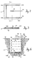
- That module includes compliant rubber pad 42 that is about sixty centimeters on a side and has a thickness of about 1/2 centimeter such that it conforms to the bottom of the excavation 10 and presents the piezoelectric sensors 30, 38 in fixed array.
- Sensors 30, 38 are of suitable piezoelectric material such as polyvinylidene fluoride (PVDF) film and each film is about two centimeters wide and fifteen centimeters long and metalized for connection to conductors 32, 40.
- PVDF polyvinylidene fluoride
- a protective sheet 44 of mylar or similar material overlies and provides protection for sensors 30, 38 and conductors 32, 40 in the excavation 10.
- the system also includes PVDF proofing sensor 50 for placement on the surface of the completely backfilled excavation and that is connected to control module 34 by conductor 52, cylindrical spacer 54 (about twenty-five centimeters in diameter and five centimeters high) that is adapted to be placed over sensor 50 and filled with backfill material, metal trigger plate 56 that is placed on the surface of the backfill material in spacer 54 and that is connected to control module 34 by conductor 58, and proofing hammer 60 that is connected to control module 34 by conductor 61.
- the striking of plate 56 by hammer 60 completes a circuit between conductors 58, 61 to activate circuits in microprocessor 84 in anticipation of a timing cycle for Proofing the backfilled excavation.
- the system also includes a sonic transmitter-receiver unit 75 that is supported on rod 77 and connected to control module by conductor 79, rod 77 being adapted to be positioned on road surface 24 to bridge hole 10 so that unit 75 is positioned directly above sensor 38 of sensor module 12 for sonic depth measurement before any lift of backfill material is placed in excavation 10.
- the portable, battery-powered control module 34 is shown in Fig. 4, and a block diagram of its circuitry is shown in Fig. 5. That module includes carrying handle 62, on/off switch 64, mode selector switch 66 that has compaction mode position 68 and proof mode position 70; reset button 72; LCD display 74 and printer output 76 that produces a printed record 78 of compaction results.
- input lines 32 are connected through adjustable gain amplifier 80 to peak detector 82 that has an input 83 from microprocessor 84.
- Microcontroller 85 includes accumulator 86 and timing counter 87; and coupled to microcontroller 85 are EPROM 88 and RAM 89.
- the output of peak detector 82 is applied through multiplex unit 88 that has an input 90 from mode selector switch 66 and analog to digital converter 92 to microcontroller 86 which provides an output over line 94 to LCD display 74 and over line 96 to printer 98.
- a second input to control module 34 is over lines 40 (from center sensor 38 through adjustable gain amplifier 100 to multiplexer 88); a third input over lines 52 from sensor 50 that is used with proofing hammer 60 and is applied through adjustable gain amplifier 102; and a fourth (trigger) input over line 58 from proofing plate 56 and line 61 from hammer 60.
- Peak detector 82 includes circuitry that accumulates peak values of signals on line 32 and averages those peak values for application through multiplexer 90 and analog to digital converter 92 for storage by accumulator 86 and display of the average value by display 74. Peak detector 82 is reset periodically (automatically by microcontroller 85) to provide a series of average impact values as sensed by sensors 30A-D.
- Processor 84 stores the magnitude of those averaged impact values (which increase as the backfill material is compacted and thus better transmits the impact energy to sensors 30) and compares the sensed impact values of preceding passes with those of the current pass and when they are substantially uniform (e.g., the average value of impact generated signals during the current pass being less than five percent greater than the average signal value during the immediately preceding pass), microprocessor 84 causes display 74 to provide an indication of satisfactory compaction of that lift.
- sensor module 12 is placed at the bottom of excavation 10 with connecting conductors 32, 38 leading up out of the excavation to the control module 34.
- the distance from the central sensor 38 to the top of the hole 10 is measured and entered into control module 34, (for example, manually or with a sonic transmitter-receiver unit 75 that is supported directly above sensor 38 by rod 77 that is positioned on road surface 24 to bridge hole 10 and a depth measurement is made sonically and entered into processor 84).
- a lift 14 of backfill material is placed in the excavation and compacted with compaction tool 22 which may be manual, pneumatic or hydraulic as appropriate depending on the particular application.
- the compaction is monitored by control module 34 in compaction mode by sensing the amplitude of signals over lines 32 from the perimeter sensors 30.
- Each compacting blow from compacting tool 22 transmits seismic energy through the backfill lift 14 to the sensors 30 which produce output voltages proportional to the sensed impact energies.
- a hydraulic compacting tool typically generates several compacting blows a second, and during each pass, the peak amplitude of signals on lines 32 as indicated by peak detector 82 is read by control module 34 at one hundred millisecond intervals and transferred through multiplexer 90 and A-D converter 92 for storage in accumulator 86.
- Peak detector 82 is reset automatically by microcontroller 85 after each interval so that a series of average impact values are stored by accumulator 86.
- Those averaged impact values (which increase as the backfill material is compacted with corresponding improvements of the transmission of impact energy to sensors 30) of a preceding pass are compared with those of the current pass and when the average value of impact generated signals during the current pass is less than a predetermined amount (e.g., five percent) greater than the average impact signal values during the immediately preceding pass, microprocessor 84 causes display 74 to provide an indication of satisfactory compaction of lift 14. Lifts 15 - 18 are similarly backfilled and compacted.
- the distance between the top of the hole 10 (original surface 24) and the surface of lift 18 is measured and entered into control module 34 as an offset from the earlier entered excavation depth measurement.
- Proofing sensor 50 is placed on the center of the top of lift 18 of the backfill material (immediately above the center sensor 38), spacer 54 is placed on the surface of backfill lift 18 surrounding sensor 50 and is filled with backfill material 79 that is compacted as appropriate to provide a thickness of about five centimeters, and proofing plate 56 is placed on top of the backfilled spacer 54, as indicated in Fig. 6.
- Mode selector switch 66 is placed in proof mode position 70 and proofing plate 56 is then struck with hammer 60, generating an initializing signal over lines 58, 61 to microprocessor 84 to initialize the microprocessor circuitry that includes timer counter 87.
- Proofing sensor 50 in response to sonic energy from proofing plate 56 transmits an impulse over lines 52 and through multiplexer 90 to microprocessor 84 to start the timer counter 87.
- the sonic energy from the hammer 60 striking plate 56 is subsequently sensed by sensor 38 and supplied over lines 40 through amplifier 100 to microprocessor 84 to stop counter 87.
- the counter value (which represents propagation time between sensors 50 and 38) is then used to calculate velocity, on the basis of the known distance between sensors 38 and 50, as an indication of the quality of compacted backfill in excavation 10.
- the parameters of that compacted backfill quality can be inputed to microprocessor 84 in terms of characteristics of the backfill material and depth of the excavation (distance between sensors 38 and 50) or the time difference (propagation time) may be displayed directly as an indication of compaction quality in terms of characteristics of the backfill material and depth of the excavation 10 based on empirical data.
- a field proofing test (FPT) device thereshown includes wood base 110 that has a thickness of about six centimeters and is of square configuration about 0.7 meters on a side.
- Groove 112 has a width of about two centimeters, a depth of about two centimeters and an inner diameter of about thirty-two centimeters.
- Seated on surface 114 is polyvinylchloride housing 116 that defines isolation chamber 118 with PVDF film sensor 120 secured on the inner surface of upper wall 122 and connected by lead 124 to monitoring circuitry of the type shown in Fig. 5.
- Housing 116 has a width of about seven centimeters, a length of about fourteen centimeters and a height of about four centimeters, and upper wall 122 has a thickness of about one centimeter.
- polyvinylchloride cylinder 126 Seated in groove 112 is polyvinylchloride cylinder 126 that has an inner diameter of about thirty-two centimeters, a height of about twenty-three centimeters and a wall thickness of about two centimeters, with annular lip 128 at its top wall surface. Seated on and mating with lip 128 is lip 130 of aluminum cylinder 132 as an extension of cylinder 126 with a height of about fifteen centimeters.
- Aluminum plate 134 is welded to and extends horizontally from the top of cylinder 132 and has holes as its four corners that receive corresponding threaded tie-rods 136 that are secured to and upstanding from base 110. Wing nuts 138 that are received on tie-rods 136 securely seat aluminum cylinder 132 on PVC cylinder 126.
- cylinders 126, 132 are filled in two lifts with a soil 140 to be tested, each lift being compacted with a tamper that has a fifteen centimeter diameter foot 142 to uniformly compact the soil in base cylinder 126.
- wing nuts 138 are released, the upper cylinder 132 is removed with care to avoid excessive disturbance of the soil 140 and the compacted soil 140 is carefully levelled as indicated in Fig. 9 so that the top surface 144 of soil 140 is level with the top of cylinder 126.
- Proofing sensor assembly 146 includes aluminum strike plate 148 that is about six centimeters square and about two centimeters thick with 0.6 centimeter deep recess 150 in which is secured PVDF film sensor 152 that is connected by lead 154 to monitoring apparatus 84. Attached to plate 148 by screw 156 is lead 158.
- Calibrated hammer assembly 160 includes polyvinylchloride guide rod 162 that has a length of about fifty centimeters and receives steel hammer member 164 of about five centimeters outer diameter and that weighs about 0.5 kilogram.
- FIG. 9 An indication of this correlation in a gravelly sand that has a Proctor of 146.2 PCF at 6.7 percent moisture is shown in Fig. 9, the soil 140 without compaction (point 170 has a percent Proctor of about 78 at a velocity of about 450 feet per second (137.16m/s); compaction of two seconds time (point 172) results in a seismic velocity of 580 feet per second or 176.784m/s (about 85 percent Proctor); compaction of about five seconds (points 174 and 176) results in a seismic velocity of about 600 feet per second (182.88m/s) which corresponds to a percent Proctor of about 87 percent; ten seconds compaction (points 178 and 180) produces seismic velocities of about 660 feet per second (201.168 m/s) which corresponds to about 92 percent Proctor; and tamping for about twenty seconds (point 182) also produces similar sonic velocities and percent Proctor in this soil.
Landscapes
- Physics & Mathematics (AREA)
- General Physics & Mathematics (AREA)
- Pathology (AREA)
- Life Sciences & Earth Sciences (AREA)
- Chemical & Material Sciences (AREA)
- Analytical Chemistry (AREA)
- Biochemistry (AREA)
- General Health & Medical Sciences (AREA)
- Health & Medical Sciences (AREA)
- Immunology (AREA)
- Acoustics & Sound (AREA)
- Investigation Of Foundation Soil And Reinforcement Of Foundation Soil By Compacting Or Drainage (AREA)
- Investigating Strength Of Materials By Application Of Mechanical Stress (AREA)
- Geophysics And Detection Of Objects (AREA)
- Investigating Or Analyzing Materials By The Use Of Ultrasonic Waves (AREA)
- Management, Administration, Business Operations System, And Electronic Commerce (AREA)
- Spectrometry And Color Measurement (AREA)
- Treatment Of Sludge (AREA)
- Soil Working Implements (AREA)
Abstract
Description
- This invention relates to monitoring systems and more particularly to methods and apparatus for monitoring soil such as compaction of backfill for utility excavations and the like.
- Excavations such as utility trenches, foundations and the like are generally backfilled in layers, termed lifts, with each lift of backfill material be compacted prior to the addition of the next lift. If backfill material is improperly compacted, or if an unsuitable backfill material is used, the backfilled excavation may subside. Subsidence in foundations, roadways or other structures due to improper backfill compaction can necessitate costly and disruptive repairs.
- In the proper compaction of backfill in an excavation, each backfill lift should be properly compacted prior to the addition of the next lift; and after all lifts are in place and compacted, the complete backfilled excavation should be proofed to verify that there are no voids, soil bridges, or layers that are not fully compacted. Current monitoring methods such as drop hammer penetration probes, nuclear densitometry and the sand cone method are typically used only to check each lift for proper compaction, and such methods are expensive, time-consuming and cannot be performed in real time.
- Tests for acceptable compaction of soil material such as Proctor or California Bearing Ratio (CBR) require specialized equipment and significant amounts of time to perform, and accordingly are usually performed in a laboratory rather than in the field.
- SU-A-1388799 discloses a method for soil compaction in which a sensor is placed together with an impacting mechanism on the working element of the compactor on the layer of soil being compacted. The product of amplitude and frequency of the working element is computed until it reaches a set value corresponding to a particular compaction of the underlying soil as determined by a prior calibration in which the product of amplitude and frequency at the working element is compared with the product of amplitude and frequency at a buried sensor.
- Gnaedinger et al in US-A-3 641 811 propose a foundation pier or caisson built of concrete. Buried within the solid concrete material as it sets is a generator for sonic pulses and a detector. Soundness of the foundation pier or caisson may be determined at any time during its lifetime by transmission of sonic pulses through the concrete.
- In contrast, the present invention, in a first aspect thereof, provides apparatus for monitoring the compaction of soil material, and including hammer structure and sensor structure; characterized in that: the sensor structure is spaced from the hammer structure; the sensor structure is arranged to be buried at the bottom of a defined region of soil material, said hammer structure being adapted for delivering impact energy to soil material in said defined region and said sensor structure being operatively adapted to develop an electric signal in response to energy transmitted through soil material from said hammer structure; and in that a control module is provided which is responsive to electric signals from said sensor structure and operatively adapted to provide an indication of the quality of compaction of soil material in said defined region.
- These features may be related to integers of a detailed embodiment described hereinbelow by way of example as follows:
- The described apparatus for monitoring the compaction of soil material includes hammer structure (22, 60) and sensor structure (12). The sensor structure is spaced from the hammer structure; and the sensor structure is arranged to be buried at the bottom of a defined region (10) of soil material, said hammer structure being adapted for delivering impact energy to soil material in said defined region and said sensor structure being signals from the sensor array for providing an indication of the quality of compaction of each lift of backfill material in the excavation, and verifying circuitry responsive to the second and third transducers for providing a transit time (dependent on seismic velocity) indication of impact energy propagation between the third transducer at the top of the backfill material and the second transducer at the bottom of the excavation.
- In a particular embodiment, the control module includes peak detection circuitry for sampling electrical signals received from the array of first piezoelectric transducers, circuitry for storing indications of the peak amplitude of signals received during a sequence of compaction intervals, circuitry responsive to the storage circuitry for providing average peak value signals during a pass of the hammer structure such as a compacting tool, comparison circuitry for comparing average peak value signals during a previous compaction pass with average peak value signals during the current compaction pass to provide an indication of the progress of the compaction process; and timing circuitry for providing an indication of impact energy propagation time through backfill material to provide an indication of acceptable compaction after the excavation backfill process has been completed.
- We also describe herein below proofing apparatus, believed novel per se, for verification of adequacy of compaction or extent of compaction of soil, that includes a first transducer for disposition at the bottom of a defined region, a second transducer for disposition on top of compacted soil in the defined region for verification of adequacy of compaction or extent of compaction of that soil, pulse generating structure for generating a seismic pulse for transmission through the soil material between the first and second transducers, and verifying circuitry responsive to the outputs of the first and second transducers for providing a time (dependent on propagation velocity) indication of energy propagation between the first and second transducers through the soil material to provide an indication of compaction quality.
- In a particular proofing apparatus, a chamber of low sonic propagation material such as molded plastic or wood is provided, a first transducer is housed in an isolation cavity in the base of the chamber, a second transducer assembly that includes a sensor and a triggering terminal is provided for disposition on the top of compacted soil material in the chamber and a calibrated sonic impulse generator in the form of a hammer and guide rod is provided for generating a seismic pulse for transmission between the two transducers through the soil material to provide an indication of the quality of the compaction of the soil material in the chamber which may be correlated with a standard test such as the Proctor Test of the California Bearing Ratio test.
- In accordance with an alternative aspect of the invention there is provided a method for proofing the compaction of soil in an excavation region comprising steps of providing chamber structure of low sonic propagation material, placing first sensor structure at the bottom of said chamber structure, placing a sample of soil in said chamber structure and compacting said soil sample to satisfy a standard test criterion, measuring the propagation time of an energy wave from the top of soil material in said chamber structure to provide a reference propagation time value indicative of satisfactory compaction, placing sensor transducer structure at the bottom of an excavation region, adding soil material to said excavation region, compacting said soil material in said excavation region with a series of compacting impacts, and measuring the propagation time of an energy wave from the top of said compacted soil material in said excavation region to said sensor transducer structure at the bottom of said excavation region to provide a propagation time value for comparison with said reference propagation time value to obtain an indication of satisfactory compaction of soil in said excavation region.
- In accordance with a yet further alternative aspect of the invention, there is provided a method for monitoring the compaction of soil in a defined region comprising the steps of: placing sensor structure at the bottom of said defined region, adding soil material to said defined region, compacting said soil material with a series of compacting impacts at a position wholly spaced from said sensor structure, and monitoring the output of said sensor structure as a function of energy from said impacts that impinge on said sensor structure.
- Preferably, the method includes the steps of accumulating amplitude signals from the sensor structure and comparing the magnitudes of those amplitudes from successive compacting passes; and after backfill has been completed, verifying the quality of soil compaction by measuring the propagation time of an energy wave from the top of the soil material to a sensor at the bottom of the soil material to provide an indication of the quality of the compaction of the soil material.
- As we shall explain below our systems provide effective real-time monitoring and verification in the field of compaction processes of soil material in a utility excavation or the like.
- Other features and advantages will be seen as the following description of particular embodiments progresses, in conjunction with the drawings, in which:
- Fig. 1 is a diagrammatic view showing aspects of a compaction monitoring system in accordance with the invention;
- Fig. 2 is a plan view of the sensor module employed in the system of Fig. 1;
- Fig. 3 is a sectional view taken along the line 3-3 of Fig. 2;
- Fig. 4 is a perspective view of the control module employed in the system of Fig. 1;
- Fig. 5 is a block diagram of circuitry of the control module of Fig. 4;
- Fig. 6 is a sectional diagrammatic view of system operation in proofing mode;
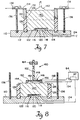
- Fig. 7 is a sectional diagrammatic view of a second system in accordance with the invention;
- Fig. 8 is a sectional diagrammatic view of a second stage of operation of the system shown in Fig. 7; and
- Fig. 9 is a graph indicating correlation between Proctor Test laboratory measurements and field use of the system shown in Figs. 7 and 8.
-
- The system diagrammatically shown in Fig. 1 includes
excavation 10 inroad surface 24 for repair ofgas line 26.Gas line 26 has been repaired,sensor module 12 is at the base ofexcavation 10 and a series of five lifts 14 - 18 of backfill material are inexcavation 10.Operator 20 is usingimpact tool 22 for compacting theuppermost lift 18.Sensor module 12 has an array of fourpiezoelectric transducer strips 30A, B, C, D that are connected in parallel byconductors 32 to battery-poweredportable control module 34 that is operated byobserver 36 and a furtherpiezoelectric transducer strip 38 that is connected byconductors 40 tocontrol module 34. - Further details of
sensor module 12 may be seen with reference to Figs. 2 and 3. That module includescompliant rubber pad 42 that is about sixty centimeters on a side and has a thickness of about 1/2 centimeter such that it conforms to the bottom of theexcavation 10 and presents thepiezoelectric sensors 30, 38 in fixed array.Sensors 30, 38 are of suitable piezoelectric material such as polyvinylidene fluoride (PVDF) film and each film is about two centimeters wide and fifteen centimeters long and metalized for connection toconductors protective sheet 44 of mylar or similar material overlies and provides protection forsensors 30, 38 andconductors excavation 10. - With reference again to Fig. 1, the system also includes
PVDF proofing sensor 50 for placement on the surface of the completely backfilled excavation and that is connected tocontrol module 34 byconductor 52, cylindrical spacer 54 (about twenty-five centimeters in diameter and five centimeters high) that is adapted to be placed oversensor 50 and filled with backfill material,metal trigger plate 56 that is placed on the surface of the backfill material inspacer 54 and that is connected tocontrol module 34 byconductor 58, andproofing hammer 60 that is connected tocontrol module 34 byconductor 61. The striking ofplate 56 byhammer 60 completes a circuit betweenconductors microprocessor 84 in anticipation of a timing cycle for Proofing the backfilled excavation. The system also includes a sonic transmitter-receiver unit 75 that is supported onrod 77 and connected to control module byconductor 79,rod 77 being adapted to be positioned onroad surface 24 tobridge hole 10 so thatunit 75 is positioned directly abovesensor 38 ofsensor module 12 for sonic depth measurement before any lift of backfill material is placed inexcavation 10. - The portable, battery-powered
control module 34 is shown in Fig. 4, and a block diagram of its circuitry is shown in Fig. 5. That module includes carryinghandle 62, on/offswitch 64,mode selector switch 66 that hascompaction mode position 68 andproof mode position 70;reset button 72;LCD display 74 andprinter output 76 that produces a printedrecord 78 of compaction results. - With reference to Fig. 5, input lines 32 (from
perimeter sensors 30A-D that are connected in parallel) are connected throughadjustable gain amplifier 80 topeak detector 82 that has an input 83 frommicroprocessor 84.Microcontroller 85 includesaccumulator 86 andtiming counter 87; and coupled tomicrocontroller 85 are EPROM 88 andRAM 89. The output ofpeak detector 82 is applied throughmultiplex unit 88 that has aninput 90 frommode selector switch 66 and analog todigital converter 92 tomicrocontroller 86 which provides an output overline 94 toLCD display 74 and overline 96 toprinter 98. A second input tocontrol module 34 is over lines 40 (fromcenter sensor 38 throughadjustable gain amplifier 100 to multiplexer 88); a third input overlines 52 fromsensor 50 that is used withproofing hammer 60 and is applied throughadjustable gain amplifier 102; and a fourth (trigger) input overline 58 fromproofing plate 56 andline 61 fromhammer 60. Peakdetector 82 includes circuitry that accumulates peak values of signals online 32 and averages those peak values for application throughmultiplexer 90 and analog todigital converter 92 for storage byaccumulator 86 and display of the average value bydisplay 74. Peakdetector 82 is reset periodically (automatically by microcontroller 85) to provide a series of average impact values as sensed bysensors 30A-D. Processor 84 stores the magnitude of those averaged impact values (which increase as the backfill material is compacted and thus better transmits the impact energy to sensors 30) and compares the sensed impact values of preceding passes with those of the current pass and when they are substantially uniform (e.g., the average value of impact generated signals during the current pass being less than five percent greater than the average signal value during the immediately preceding pass),microprocessor 84 causesdisplay 74 to provide an indication of satisfactory compaction of that lift. - In system use, with reference to Fig. 6, after
gas line 26 at the base ofutility excavation 10 has been covered with a thin layer of backfill material,sensor module 12 is placed at the bottom ofexcavation 10 with connectingconductors control module 34. The distance from thecentral sensor 38 to the top of thehole 10 is measured and entered intocontrol module 34, (for example, manually or with a sonic transmitter-receiver unit 75 that is supported directly abovesensor 38 byrod 77 that is positioned onroad surface 24 to bridgehole 10 and a depth measurement is made sonically and entered into processor 84). Alift 14 of backfill material is placed in the excavation and compacted withcompaction tool 22 which may be manual, pneumatic or hydraulic as appropriate depending on the particular application. As thelift 14 is being compacted in a series of "passes", the compaction is monitored bycontrol module 34 in compaction mode by sensing the amplitude of signals overlines 32 from the perimeter sensors 30. Each compacting blow from compactingtool 22 transmits seismic energy through thebackfill lift 14 to the sensors 30 which produce output voltages proportional to the sensed impact energies. A hydraulic compacting tool typically generates several compacting blows a second, and during each pass, the peak amplitude of signals onlines 32 as indicated bypeak detector 82 is read bycontrol module 34 at one hundred millisecond intervals and transferred throughmultiplexer 90 andA-D converter 92 for storage inaccumulator 86. Peakdetector 82 is reset automatically bymicrocontroller 85 after each interval so that a series of average impact values are stored byaccumulator 86. Those averaged impact values (which increase as the backfill material is compacted with corresponding improvements of the transmission of impact energy to sensors 30) of a preceding pass are compared with those of the current pass and when the average value of impact generated signals during the current pass is less than a predetermined amount (e.g., five percent) greater than the average impact signal values during the immediately preceding pass,microprocessor 84 causesdisplay 74 to provide an indication of satisfactory compaction oflift 14. Lifts 15 - 18 are similarly backfilled and compacted. - After the several lifts 14 - 18 have been satisfactorily compacted in sequence, the distance between the top of the hole 10 (original surface 24) and the surface of
lift 18 is measured and entered intocontrol module 34 as an offset from the earlier entered excavation depth measurement.Proofing sensor 50 is placed on the center of the top oflift 18 of the backfill material (immediately above the center sensor 38),spacer 54 is placed on the surface ofbackfill lift 18 surroundingsensor 50 and is filled withbackfill material 79 that is compacted as appropriate to provide a thickness of about five centimeters, andproofing plate 56 is placed on top of thebackfilled spacer 54, as indicated in Fig. 6.Mode selector switch 66 is placed inproof mode position 70 andproofing plate 56 is then struck withhammer 60, generating an initializing signal overlines microprocessor 84 to initialize the microprocessor circuitry that includestimer counter 87. Proofingsensor 50 in response to sonic energy fromproofing plate 56 transmits an impulse overlines 52 and throughmultiplexer 90 tomicroprocessor 84 to start thetimer counter 87. The sonic energy from thehammer 60striking plate 56 is subsequently sensed bysensor 38 and supplied overlines 40 throughamplifier 100 tomicroprocessor 84 to stopcounter 87. The counter value (which represents propagation time betweensensors 50 and 38) is then used to calculate velocity, on the basis of the known distance betweensensors excavation 10. The parameters of that compacted backfill quality can be inputed tomicroprocessor 84 in terms of characteristics of the backfill material and depth of the excavation (distance betweensensors 38 and 50) or the time difference (propagation time) may be displayed directly as an indication of compaction quality in terms of characteristics of the backfill material and depth of theexcavation 10 based on empirical data. - With reference to Fig. 7, a field proofing test (FPT) device thereshown includes
wood base 110 that has a thickness of about six centimeters and is of square configuration about 0.7 meters on a side.Groove 112 has a width of about two centimeters, a depth of about two centimeters and an inner diameter of about thirty-two centimeters. Seated onsurface 114 ispolyvinylchloride housing 116 that definesisolation chamber 118 withPVDF film sensor 120 secured on the inner surface ofupper wall 122 and connected bylead 124 to monitoring circuitry of the type shown in Fig. 5.Housing 116 has a width of about seven centimeters, a length of about fourteen centimeters and a height of about four centimeters, andupper wall 122 has a thickness of about one centimeter. - Seated in
groove 112 ispolyvinylchloride cylinder 126 that has an inner diameter of about thirty-two centimeters, a height of about twenty-three centimeters and a wall thickness of about two centimeters, withannular lip 128 at its top wall surface. Seated on and mating withlip 128 islip 130 ofaluminum cylinder 132 as an extension ofcylinder 126 with a height of about fifteen centimeters.Aluminum plate 134 is welded to and extends horizontally from the top ofcylinder 132 and has holes as its four corners that receive corresponding threaded tie-rods 136 that are secured to and upstanding frombase 110.Wing nuts 138 that are received on tie-rods 136 securely seataluminum cylinder 132 onPVC cylinder 126. - In use of the field proofing test (FPT) device,
cylinders soil 140 to be tested, each lift being compacted with a tamper that has a fifteencentimeter diameter foot 142 to uniformly compact the soil inbase cylinder 126. After compaction,wing nuts 138 are released, theupper cylinder 132 is removed with care to avoid excessive disturbance of thesoil 140 and the compactedsoil 140 is carefully levelled as indicated in Fig. 9 so that thetop surface 144 ofsoil 140 is level with the top ofcylinder 126. - Proofing
sensor assembly 146 includesaluminum strike plate 148 that is about six centimeters square and about two centimeters thick with 0.6 centimeterdeep recess 150 in which is securedPVDF film sensor 152 that is connected bylead 154 tomonitoring apparatus 84. Attached to plate 148 byscrew 156 is lead 158. Calibratedhammer assembly 160 includespolyvinylchloride guide rod 162 that has a length of about fifty centimeters and receivessteel hammer member 164 of about five centimeters outer diameter and that weighs about 0.5 kilogram. - When proofing
hammer 164 is dropped from a height of forty centimeters on striking plate 148 a signal is produced overline 158 to microprocessor 84B to initialize themicroprocessor circuitry 84 that includestimer counter 87 in anticipation of a timing cycle for measuring the quality of compaction of thesoil 140.Proofing sensor 152 in response to sonic energy fromplate 144 transmits an impulse overline 158 to themicroprocessor 84 to start thetiming counter 87. The seismic energy transmitted throughsoil 140 is sensed bysensor 120 and transmitted overline 124 as a second input to counter 87 and the resulting counter value (which represents propagation time betweensensors 152 and 120) is used to calculate propagation velocity which correlates with Proctor Test data obtained in the laboratory. An indication of this correlation in a gravelly sand that has a Proctor of 146.2 PCF at 6.7 percent moisture is shown in Fig. 9, thesoil 140 without compaction (point 170 has a percent Proctor of about 78 at a velocity of about 450 feet per second (137.16m/s); compaction of two seconds time (point 172) results in a seismic velocity of 580 feet per second or 176.784m/s (about 85 percent Proctor); compaction of about five seconds (points 174 and 176) results in a seismic velocity of about 600 feet per second (182.88m/s) which corresponds to a percent Proctor of about 87 percent; ten seconds compaction (points 178 and 180) produces seismic velocities of about 660 feet per second (201.168 m/s) which corresponds to about 92 percent Proctor; and tamping for about twenty seconds (point 182) also produces similar sonic velocities and percent Proctor in this soil. - Using that data as an example, if it is desired to have a minimum of 90 percent Proctor in the excavation, then the operator loads the FPT with the unknown soil, and compacts for a minimum of ten seconds to achieve a minimum of 90 percent Proctor. A velocity measurement using the procedure described above finds that soil exhibits a velocity of 625 feet per second (190.5m/s). The 625 feet per second value becomes the performance goal for compaction of the backfill material in the field.
Claims (9)
- Apparatus for monitoring the compaction of soil material, and including hammer structure and sensor structure; characterized in that: the sensor structure is spaced from the hammer structure; the sensor structure is arranged to be buried at the bottom of a defined region of soil material, said hammer structure being adapted for delivering impact energy to soil material in said defined region and said sensor structure being operatively adapted to develop an electric signal in response to energy transmitted through soil material from said hammer structure; and in that a control module is provided which is responsive to electric signals from said sensor structure and operatively adapted to provide an indication of the quality of compaction of soil material in said defined region.
- Apparatus according to Claim 1, further characterised in that said control module has a compaction mode for monitoring the progress of compaction of individual lifts and a proofing mode for providing an indication of acceptable compaction of soil material in said defined region.
- Apparatus according to Claim 1 or Claim 2, further characterised in that said sensor structure includes a compliant base member of electrically insulating material, a plurality of first piezoelectric transducers secured in spaced array on said base member and connected in parallel to first output conductor structure, a second piezoelectric transducer secured on said base member and connected to second output conductor structure, said output conductor structures being connected to said control module for transmitting electrical signals to said control module, and protective sheet structure overlying said transducers.
- Apparatus according to Claim 3, further characterised in that said control module includes accumulator circuitry for operatively accumulating output signals from said sensor structure for providing an indication of the quality of compaction of each lift of soil material in said defined region, verifying circuitry adapted to be responsive to a transducer on said sensor structure and to another transducer which may be located at the top of said soil material for providing a transit time indication of impact energy propagation between said another transducer and the said transducer on said sensor structure, peak detection circuitry for sampling electrical signals received from the array of first piezoelectric elements, circuitry for storing indications of the peak of largest magnitude received during a sequence of compaction impacts, circuitry responsive to said storage circuitry for providing average peak value signals during a pass of said hammer structure, and comparison circuitry for comparing the average peak value signals during a previous compaction pass with average peak value signals during the current compaction pass to provide an indication of the progress of the compaction process; and in that said control module includes timing circuitry for providing an indication of impact energy propagation time through soil material in said defined region to provide an indication of acceptable soil compaction.
- Apparatus according to any preceding claim, characterised in further including chamber structure of low sonic propagation material, isolation cavity structure in the base of said chamber structure for housing a first transducer, a second transducer assembly that includes sensor and triggering terminal structure for disposition on the top of compacted soil material in said chamber structure, and pulse generating structure that includes said hammer structure for generating a seismic pulse for transmission between said two transducers through the soil material to provide an indication of the quality of the compaction of the soil material in said chamber structure which may be correlated with a standard test.
- A method for monitoring the compaction of soil in a defined region comprising the steps of:placing sensor structure at the bottom of said defined region, adding soil material to said defined region, compacting said soil material with a series of compacting impacts at a position wholly spaced from said sensor structure, and monitoring the output of said sensor structure as a function of energy from said impacts that impinge on said sensor structure.
- A method according to Claim 6, further including the steps of accumulating a plurality of impact signals from said sensor during a compaction pass to provide an indication of the progress of the compaction process; and measuring the propagation time of the energy wave from the top of said soil material to said sensor structure to provide an indication of the quality of the compaction of said soil material.
- A method according to either Claim 6 or Claim 7, wherein said sensor structure includes a compliant base member of electrically-insulating material on which a plurality of piezoelectric transducers are secured in spaced array, and said base member has an area at least about one-half the base area of said excavation; the method further including a compaction mode step that includes accumulation of a plurality of impact signals from said transducers during a compaction pass to provide an indication of the progress of the compaction process, and a proofing mode step that includes measuring the propagation time of an energy wave from the top of soil material in said defined region to a piezoelectric transducer at the bottom of said defined region to provide an indication of the quality of the compaction of the soil material in said defined region.
- A method for proofing the compaction of soil in an excavation region comprising steps of providing chamber structure of low sonic propagation material, placing first sensor structure at the bottom of said chamber structure, placing a sample of soil in said chamber structure and compacting said soil sample to satisfy a standard test criterion, measuring the propagation time of an energy wave from the top of soil material in said chamber structure to provide a reference propagation time value indicative of satisfactory compaction, placing sensor transducer structure at the bottom of an excavation region, adding soil material to said excavation region, compacting said soil material in said excavation region with a series of compacting impacts, and measuring the propagation time of an energy wave from the top of said compacted soil material in said excavation region to said sensor transducer structure at the bottom of said excavation region to provide a propagation time value for comparison with said reference propagation time value to obtain an indication of satisfactory compaction of soil in said excavation region.
Applications Claiming Priority (3)
| Application Number | Priority Date | Filing Date | Title |
|---|---|---|---|
| US07/490,751 US5105650A (en) | 1990-03-08 | 1990-03-08 | Monitoring compaction of backfill |
| US490751 | 1990-03-08 | ||
| PCT/US1991/001573 WO1991014182A1 (en) | 1990-03-08 | 1991-03-07 | Monitoring of soil |
Publications (3)
| Publication Number | Publication Date |
|---|---|
| EP0518996A1 EP0518996A1 (en) | 1992-12-23 |
| EP0518996A4 EP0518996A4 (en) | 1993-12-01 |
| EP0518996B1 true EP0518996B1 (en) | 2000-09-06 |
Family
ID=23949307
Family Applications (1)
| Application Number | Title | Priority Date | Filing Date |
|---|---|---|---|
| EP91906443A Expired - Lifetime EP0518996B1 (en) | 1990-03-08 | 1991-03-07 | Monitoring of soil |
Country Status (8)
| Country | Link |
|---|---|
| US (2) | US5105650A (en) |
| EP (1) | EP0518996B1 (en) |
| JP (1) | JPH05505674A (en) |
| AU (1) | AU649031B2 (en) |
| CA (1) | CA2077353C (en) |
| DE (1) | DE69132405T2 (en) |
| ES (1) | ES2152921T3 (en) |
| WO (1) | WO1991014182A1 (en) |
Cited By (1)
| Publication number | Priority date | Publication date | Assignee | Title |
|---|---|---|---|---|
| CN105865875A (en) * | 2016-05-18 | 2016-08-17 | 北京安赛博技术有限公司 | Experimental device for keeping consistency of soil physical properties |
Families Citing this family (34)
| Publication number | Priority date | Publication date | Assignee | Title |
|---|---|---|---|---|
| US5105650A (en) * | 1990-03-08 | 1992-04-21 | Gas Research Institute | Monitoring compaction of backfill |
| US5426972A (en) * | 1993-04-20 | 1995-06-27 | Gas Research Institute | Monitoring soil compaction |
| US6604432B1 (en) | 1996-02-01 | 2003-08-12 | Bbn Corporation | Soil compaction measurement |
| US6912903B2 (en) * | 1996-02-01 | 2005-07-05 | Bbnt Solutions Llc | Soil compaction measurement |
| US6726969B1 (en) * | 1997-01-28 | 2004-04-27 | Avery Dennison Corporation | In-mold labels and uses thereof |
| US6244102B1 (en) | 1998-09-18 | 2001-06-12 | Dynasens Ltd. | Method and system for examination and optimal compaction of soil enbankments |
| FR2785310B1 (en) * | 1998-10-30 | 2001-01-26 | Paris Eaux Gestion | METHOD AND APPARATUS FOR CONTROLLING THE COMPACTION OF A BACKFILL |
| JP3457258B2 (en) * | 2000-05-29 | 2003-10-14 | 株式会社東建工営 | A method for measuring a change in soil strength, and a measuring device therefor. |
| US6859732B2 (en) * | 2002-09-16 | 2005-02-22 | Philip A. Tritico | Methods in the engineering design and construction of earthen fills |
| US7110884B2 (en) * | 2001-05-15 | 2006-09-19 | Earthworks Solutions, Inc. | Methods in the engineering design and construction of earthen fills |
| CA2447157C (en) * | 2001-05-15 | 2012-08-21 | Industry Advocates, Inc. | Monitoring fill soil via compactor rolling resistance |
| US6386037B1 (en) * | 2001-06-06 | 2002-05-14 | The United States Of America As Represented By The Secretary Of The Interior | Void detector for buried pipelines and conduits using acoustic resonance |
| JP3658382B2 (en) * | 2001-08-21 | 2005-06-08 | キヤノン株式会社 | Signal output apparatus, sheet material discrimination method, image forming apparatus, sheet material conveying apparatus, and signal output method |
| US20080004809A1 (en) * | 2002-09-16 | 2008-01-03 | Earthwork Solutions, Inc. | Engineering design and construction of earthen fills |
| US20120078515A1 (en) * | 2002-09-16 | 2012-03-29 | Earthwork Solutions, Llc | Engineering design and construction of earthen fills |
| US7073374B2 (en) * | 2003-07-30 | 2006-07-11 | Bbnt Solutions Llc | Soil compaction measurement on moving platform |
| US7451650B2 (en) * | 2004-08-27 | 2008-11-18 | General Electric Company | Systems and methods for adjusting gain within an ultrasound probe |
| US7669458B2 (en) * | 2004-11-10 | 2010-03-02 | The Board Of Regents Of The University Of Oklahoma | Method and apparatus for predicting density of asphalt |
| US20060266119A1 (en) * | 2005-05-23 | 2006-11-30 | Applied Sonics, Incorporated | Ultrasonic system for on-line monitoring of pressed materials |
| RU2456409C2 (en) * | 2006-12-19 | 2012-07-20 | Лоудтест, Инк. | Method to test bearing capacity using circular sensor (versions) |
| US11174458B2 (en) | 2007-04-23 | 2021-11-16 | Koligo Therapeutics, Inc. | Cell separation apparatus and methods of use |
| CN101216387B (en) * | 2007-12-27 | 2010-06-02 | 浙江大学 | A Hollow Cylindrical Torsional Shear Apparatus Remodeling Sample Compactor |
| US7945388B2 (en) * | 2008-06-25 | 2011-05-17 | The Boeing Company | Test bed for in-situ studies |
| US8033156B2 (en) * | 2008-06-25 | 2011-10-11 | The Boeing Company | Sensor apparatus and method for detecting impacts |
| US8190338B2 (en) | 2008-09-02 | 2012-05-29 | The Board Of Regents Of The University Of Oklahoma | Method and apparatus for compaction of roadway materials |
| BR112012029313B1 (en) | 2010-05-18 | 2021-07-13 | Loadtest, Inc | METHOD OF APPLYING A LOAD TO A STAKE AND LOAD CELL |
| CN103120979A (en) * | 2012-12-28 | 2013-05-29 | 山东省农业科学院农业资源与环境研究所 | Soil sample smashing device and working method thereof |
| CN103267664B (en) * | 2013-05-08 | 2015-01-28 | 新疆农业科学院农业质量标准与检测技术研究所 | Soil standard sample and application thereof |
| CN109763476B (en) * | 2019-03-12 | 2024-06-28 | 上海兰德公路工程咨询设计有限公司 | Device and method for rapidly detecting compactness of filled roadbed |
| JP6705525B1 (en) * | 2019-03-14 | 2020-06-03 | 日本電気株式会社 | Soil condition estimating device, soil condition estimating method, and program |
| JP6795050B2 (en) | 2019-03-14 | 2020-12-02 | 日本電気株式会社 | Plant monitoring equipment, plant monitoring methods, and programs |
| CN110670641B (en) * | 2019-09-18 | 2024-01-19 | 中国电建集团山东电力建设第一工程有限公司 | A safety detection device and method for deep foundation pit excavation in thermal power plants |
| CN113738340B (en) * | 2021-09-01 | 2024-07-19 | 苏州南智传感科技有限公司 | Real-time monitoring device and monitoring method for backfill progress of drilling |
| CN113916694B (en) * | 2021-10-29 | 2023-05-02 | 重庆电子工程职业学院 | Intelligent touch system |
Family Cites Families (36)
| Publication number | Priority date | Publication date | Assignee | Title |
|---|---|---|---|---|
| US2284707A (en) * | 1940-01-18 | 1942-06-02 | Francis J Wilson | Apparatus for measuring soil or hydrostatic pressures |
| US2336500A (en) * | 1942-05-29 | 1943-12-14 | Johj O Osterberg | Apparatus for determining soil and hydrostatic pressure |
| US2624251A (en) * | 1947-10-03 | 1953-01-06 | Porter Omer James | Apparatus for earth compaction |
| US3286514A (en) * | 1964-03-20 | 1966-11-22 | Curtis A Anderson | Total pressure transducer |
| US3456496A (en) * | 1966-03-29 | 1969-07-22 | Us Navy | Dynamic soil strain gage sensor and apparatus |
| US3372577A (en) * | 1967-01-12 | 1968-03-12 | Interior Usa | Pressure measuring device employing a diaphragm and strain gages |
| US3492859A (en) * | 1967-08-22 | 1970-02-03 | Alexander Dodge | Hydraulic pressure measuring system |
| US3529468A (en) * | 1968-01-02 | 1970-09-22 | Teledyne Inc | Meter for measuring compressive stress in earthen masses and the like |
| US3537541A (en) * | 1968-07-02 | 1970-11-03 | Sinclair Research Inc | Acoustic bomb and transducer apparatus |
| US3641811A (en) * | 1969-12-02 | 1972-02-15 | Robert J Gnaedinger Jr | Method and apparatus for determining structural characteristics |
| US4149253A (en) * | 1970-11-21 | 1979-04-10 | Losenhausen Maschinenbau Ag | Soil compacting apparatus |
| JPS5152613A (en) * | 1974-11-01 | 1976-05-10 | Nippon Dev Consult | JIBANNOSHIMEKATAMETOKUSEISOKUTEIHOTO SONOSOCHI |
| US3998090A (en) * | 1975-11-07 | 1976-12-21 | The United States Of America As Represented By The Secretary Of The Army | Soil compactor |
| US4103554A (en) * | 1976-03-12 | 1978-08-01 | Thurner Heinz F | Method and a device for ascertaining the degree of compaction of a bed of material with a vibratory compacting device |
| DE2942334C2 (en) * | 1979-10-19 | 1984-06-28 | Koehring Gmbh - Bomag Division, 5407 Boppard | Device for monitoring the degree of compaction |
| SU973702A1 (en) * | 1981-04-24 | 1982-11-15 | Ордена Трудового Красного Знамени Научно-Исследовательский Институт Оснований И Подземных Сооружений Им.Н.М.Герсеванова | Instrument for compression testing of soil |
| US4398427A (en) * | 1981-06-05 | 1983-08-16 | Exxon Production Research Co. | Thin shell pressure sensor |
| DE3236098A1 (en) * | 1982-09-29 | 1984-03-29 | Siemens AG, 1000 Berlin und 8000 München | PRESSURE CONVERTER ARRANGEMENT, ESPECIALLY FOR INDUSTRIAL ROBOTS |
| JPS59141028A (en) * | 1983-01-31 | 1984-08-13 | Nissan Motor Co Ltd | Washer type pressure sensor |
| US4524626A (en) * | 1983-10-11 | 1985-06-25 | Iowa State University Research Foundation, Inc. | Soil effective stress sensor and method of using same |
| SE455002B (en) * | 1984-05-08 | 1988-06-13 | Nilsson Peter | METHOD DEVICE FOR SEATING THE PROCESSING SIZE IN BUILDING MATERIAL FOR DAMAGE AND WALL BUILDING DAMAGES |
| US4543820A (en) * | 1984-05-17 | 1985-10-01 | Iowa State University Research Foundation, Inc. | Tapered blade in situ soil testing device |
| US4614110A (en) * | 1984-06-08 | 1986-09-30 | Osterberg Jorj O | Device for testing the load-bearing capacity of concrete-filled earthen shafts |
| US4662226A (en) * | 1985-01-29 | 1987-05-05 | Desheng Wang | Pressure transducer |
| SU1318653A1 (en) * | 1985-12-02 | 1987-06-23 | Уральский политехнический институт им.С.М.Кирова | Vibrostabilometric unit for testing large-lump soil |
| JPS62134557A (en) * | 1985-12-09 | 1987-06-17 | Tokyo Keiki Co Ltd | Analogue signal output apparatus for ultrasonic flaw detector of multiplexer system |
| SU1449864A1 (en) * | 1986-02-26 | 1989-01-07 | Уральский электромеханический институт инженеров железнодорожного транспорта им.Я.М.Свердлова | Method and apparatus for investigating compaction of grounds |
| SU1388799A1 (en) * | 1986-10-08 | 1988-04-15 | Научно-Исследовательский Институт Промышленного Строительства | Method of checking ground compaction |
| DE3680341D1 (en) * | 1986-11-07 | 1991-08-22 | Kristal Instr Ag | MULTI-COMPONENT DYNAMOMETER. |
| JP2523324B2 (en) * | 1987-06-09 | 1996-08-07 | 建設省土木研究所長 | How to measure the degree of compaction of the ground |
| US4856318A (en) * | 1987-07-20 | 1989-08-15 | Playground Clearing House, Inc. | Surface resiliency tester |
| GB8802626D0 (en) * | 1988-02-05 | 1988-03-02 | Geotechnics Ltd | Impact testing apparatus |
| US5054490A (en) * | 1988-05-11 | 1991-10-08 | Lunar Corporation | Ultrasonic densitometer device and method |
| CA1323683C (en) * | 1988-09-30 | 1993-10-26 | Michel J. Pettigrew | Loose rock detector |
| US5247937A (en) * | 1989-11-17 | 1993-09-28 | Board Of Regents, The University Of Texas System | Transaxial compression technique for sound velocity estimation |
| US5105650A (en) * | 1990-03-08 | 1992-04-21 | Gas Research Institute | Monitoring compaction of backfill |
-
1990
- 1990-03-08 US US07/490,751 patent/US5105650A/en not_active Expired - Lifetime
-
1991
- 1991-03-07 JP JP91506404A patent/JPH05505674A/en active Pending
- 1991-03-07 AU AU75450/91A patent/AU649031B2/en not_active Ceased
- 1991-03-07 WO PCT/US1991/001573 patent/WO1991014182A1/en not_active Ceased
- 1991-03-07 EP EP91906443A patent/EP0518996B1/en not_active Expired - Lifetime
- 1991-03-07 US US07/934,611 patent/US5402667A/en not_active Expired - Lifetime
- 1991-03-07 DE DE69132405T patent/DE69132405T2/en not_active Expired - Fee Related
- 1991-03-07 ES ES91906443T patent/ES2152921T3/en not_active Expired - Lifetime
- 1991-03-07 CA CA002077353A patent/CA2077353C/en not_active Expired - Fee Related
Cited By (1)
| Publication number | Priority date | Publication date | Assignee | Title |
|---|---|---|---|---|
| CN105865875A (en) * | 2016-05-18 | 2016-08-17 | 北京安赛博技术有限公司 | Experimental device for keeping consistency of soil physical properties |
Also Published As
| Publication number | Publication date |
|---|---|
| CA2077353A1 (en) | 1991-09-09 |
| ES2152921T3 (en) | 2001-02-16 |
| JPH05505674A (en) | 1993-08-19 |
| DE69132405D1 (en) | 2000-10-12 |
| US5402667A (en) | 1995-04-04 |
| AU649031B2 (en) | 1994-05-12 |
| CA2077353C (en) | 1999-06-29 |
| EP0518996A1 (en) | 1992-12-23 |
| AU7545091A (en) | 1991-10-10 |
| DE69132405T2 (en) | 2001-06-28 |
| WO1991014182A1 (en) | 1991-09-19 |
| EP0518996A4 (en) | 1993-12-01 |
| US5105650A (en) | 1992-04-21 |
Similar Documents
| Publication | Publication Date | Title |
|---|---|---|
| US5402667A (en) | Monitoring of soil | |
| Holeyman | Keynote lecture: Technology of pile dynamic testing | |
| CA2479782C (en) | Wireless apparatus and method for analysis of driven piles | |
| KR101067576B1 (en) | Indoor measuring method and device for compaction characteristics of fill material | |
| US5581013A (en) | Method and system for obtaining useful foundation information | |
| AU2002244316A1 (en) | Wireless apparatus and method for analysis of piles | |
| US7082831B2 (en) | Measurement of base and subgrade layer stiffness using bender element technique | |
| AU2004202923A1 (en) | Method and Apparatus for Testing Installation Quality in a Grouted Anchor System | |
| EP0471733A1 (en) | Pile tester. | |
| CN110306606B (en) | Pile foundation quality monitoring method and device for construction process | |
| Scott et al. | Full-scale dynamic lateral pile tests | |
| Akbar et al. | A flat dilatometer to operate in glacial tills | |
| Schmertmann | Effect of shear stress on dynamic bulk modulus of sand | |
| US7669481B2 (en) | System for monitoring level variations in a soil subjected to erosive and sedimentary agents, and monitoring method and element | |
| Liang et al. | Wave equation parameters from driven-rod test | |
| EP1338704B1 (en) | Measurement of the compaction rate of granular material layers | |
| Selig et al. | Evaluation of dynamic earth pressure cells for subgrade | |
| CN117589887B (en) | Impact hammer quality detection device and method of standard impact device and electronic equipment | |
| Fleming | Impact assessment of highway foundation layers | |
| Parvizi et al. | Centrifuge modeling of soil improvement by Low Energy Dynamic Compaction (LEDC) | |
| Weiguo et al. | Installation of a system for dynamic measurement of a model pile | |
| SU1762219A1 (en) | Method of determination of strength of materials | |
| Ooi et al. | An innovative method of load testing deep foundations | |
| RU1778679C (en) | Acoustic-emission method for determining stresses in reinforced-concrete piles | |
| RU2052585C1 (en) | Method for dynamic test of foundation base |
Legal Events
| Date | Code | Title | Description |
|---|---|---|---|
| PUAI | Public reference made under article 153(3) epc to a published international application that has entered the european phase |
Free format text: ORIGINAL CODE: 0009012 |
|
| 17P | Request for examination filed |
Effective date: 19920904 |
|
| AK | Designated contracting states |
Kind code of ref document: A1 Designated state(s): DE ES FR GB IT NL |
|
| A4 | Supplementary search report drawn up and despatched |
Effective date: 19931011 |
|
| AK | Designated contracting states |
Kind code of ref document: A4 Designated state(s): DE ES FR GB IT NL |
|
| RAP1 | Party data changed (applicant data changed or rights of an application transferred) |
Owner name: GAS RESEARCH INSTITUTE |
|
| 17Q | First examination report despatched |
Effective date: 19951220 |
|
| GRAG | Despatch of communication of intention to grant |
Free format text: ORIGINAL CODE: EPIDOS AGRA |
|
| GRAG | Despatch of communication of intention to grant |
Free format text: ORIGINAL CODE: EPIDOS AGRA |
|
| GRAH | Despatch of communication of intention to grant a patent |
Free format text: ORIGINAL CODE: EPIDOS IGRA |
|
| GRAH | Despatch of communication of intention to grant a patent |
Free format text: ORIGINAL CODE: EPIDOS IGRA |
|
| GRAA | (expected) grant |
Free format text: ORIGINAL CODE: 0009210 |
|
| AK | Designated contracting states |
Kind code of ref document: B1 Designated state(s): DE ES FR GB IT NL |
|
| REF | Corresponds to: |
Ref document number: 69132405 Country of ref document: DE Date of ref document: 20001012 |
|
| ITF | It: translation for a ep patent filed | ||
| ET | Fr: translation filed | ||
| REG | Reference to a national code |
Ref country code: ES Ref legal event code: FG2A Ref document number: 2152921 Country of ref document: ES Kind code of ref document: T3 |
|
| PGFP | Annual fee paid to national office [announced via postgrant information from national office to epo] |
Ref country code: ES Payment date: 20010323 Year of fee payment: 11 |
|
| PGFP | Annual fee paid to national office [announced via postgrant information from national office to epo] |
Ref country code: NL Payment date: 20010330 Year of fee payment: 11 |
|
| PLBE | No opposition filed within time limit |
Free format text: ORIGINAL CODE: 0009261 |
|
| STAA | Information on the status of an ep patent application or granted ep patent |
Free format text: STATUS: NO OPPOSITION FILED WITHIN TIME LIMIT |
|
| 26N | No opposition filed | ||
| REG | Reference to a national code |
Ref country code: GB Ref legal event code: IF02 |
|
| PG25 | Lapsed in a contracting state [announced via postgrant information from national office to epo] |
Ref country code: ES Free format text: LAPSE BECAUSE OF NON-PAYMENT OF DUE FEES Effective date: 20020308 |
|
| PG25 | Lapsed in a contracting state [announced via postgrant information from national office to epo] |
Ref country code: NL Free format text: LAPSE BECAUSE OF NON-PAYMENT OF DUE FEES Effective date: 20021001 |
|
| NLV4 | Nl: lapsed or anulled due to non-payment of the annual fee |
Effective date: 20021001 |
|
| REG | Reference to a national code |
Ref country code: ES Ref legal event code: FD2A Effective date: 20030410 |
|
| PG25 | Lapsed in a contracting state [announced via postgrant information from national office to epo] |
Ref country code: IT Free format text: LAPSE BECAUSE OF NON-PAYMENT OF DUE FEES Effective date: 20050307 |
|
| PGFP | Annual fee paid to national office [announced via postgrant information from national office to epo] |
Ref country code: GB Payment date: 20090223 Year of fee payment: 19 |
|
| PGFP | Annual fee paid to national office [announced via postgrant information from national office to epo] |
Ref country code: DE Payment date: 20090331 Year of fee payment: 19 |
|
| PGFP | Annual fee paid to national office [announced via postgrant information from national office to epo] |
Ref country code: FR Payment date: 20090101 Year of fee payment: 19 |
|
| GBPC | Gb: european patent ceased through non-payment of renewal fee |
Effective date: 20100307 |
|
| REG | Reference to a national code |
Ref country code: FR Ref legal event code: ST Effective date: 20101130 |
|
| PG25 | Lapsed in a contracting state [announced via postgrant information from national office to epo] |
Ref country code: FR Free format text: LAPSE BECAUSE OF NON-PAYMENT OF DUE FEES Effective date: 20100331 |
|
| PG25 | Lapsed in a contracting state [announced via postgrant information from national office to epo] |
Ref country code: DE Free format text: LAPSE BECAUSE OF NON-PAYMENT OF DUE FEES Effective date: 20101001 |
|
| PG25 | Lapsed in a contracting state [announced via postgrant information from national office to epo] |
Ref country code: GB Free format text: LAPSE BECAUSE OF NON-PAYMENT OF DUE FEES Effective date: 20100307 |