EP0518906B1 - Earwax trap for use with hearing-aid apparatus, and hearing-aid apparatus with such a trap - Google Patents
Earwax trap for use with hearing-aid apparatus, and hearing-aid apparatus with such a trap Download PDFInfo
- Publication number
- EP0518906B1 EP0518906B1 EP91905011A EP91905011A EP0518906B1 EP 0518906 B1 EP0518906 B1 EP 0518906B1 EP 91905011 A EP91905011 A EP 91905011A EP 91905011 A EP91905011 A EP 91905011A EP 0518906 B1 EP0518906 B1 EP 0518906B1
- Authority
- EP
- European Patent Office
- Prior art keywords
- space
- earwax
- hearing
- trap
- aid apparatus
- Prior art date
- Legal status (The legal status is an assumption and is not a legal conclusion. Google has not performed a legal analysis and makes no representation as to the accuracy of the status listed.)
- Expired - Lifetime
Links
Images

Classifications
-
- H—ELECTRICITY
- H04—ELECTRIC COMMUNICATION TECHNIQUE
- H04R—LOUDSPEAKERS, MICROPHONES, GRAMOPHONE PICK-UPS OR LIKE ACOUSTIC ELECTROMECHANICAL TRANSDUCERS; ELECTRIC HEARING AIDS; PUBLIC ADDRESS SYSTEMS
- H04R25/00—Electric hearing aids
- H04R25/65—Housing parts, e.g. shells, tips or moulds, or their manufacture
- H04R25/652—Ear tips; Ear moulds
- H04R25/654—Ear wax retarders
Definitions
- the present invention relates to an earwax trap of the kind set forth in the preamble of claim 1.
- Earwax traps of this kind are known from the European Patent Application No. O 326 513 and Japanese Patent Publication No. 55-61194.
- the earwax traps thus known, there are no means to remove the earwax, which has to be removed by external means, such as pipe cleaners or the like, which may damage the earwax trap and/or internal parts of the hearing-aid apparatus, such as the so-called receiver converting electric signals into sound.
- the piston- or plug-shaped member is always present in the earwax trap, and when it is moved in the first direction mentioned in the claim, it will push any earwax having collected of out the trap, and when it is moved in the opposite direction, it no longer constitutes an obstruction in the acoustical path.
- Claims 2-6 relate to advantageous embodiments of the earwax trap according to the present invention, the effects of which embodiments are explained in more detail in the following detailed portion of the present specification.
- the present invention also relates to a hearing-aid apparatus of the kind set forth in the preamble of claim 7, and according to the present invention, this apparatus is characterized as set forth in the characterizing clause of claim 7.
- Figure 1 shows an insertion portion 1 of a hearing-aid apparatus, of which only the components relevant to the present invention are shown, i.e.
- the connecting piece 2 is also adapted to prevent earwax from the user's external auditory meatus from entering and eventually blocking the acoustical conduit leading from the receiver 3 to the outside of the insertion portion 1, in a manner to be explained in more detail below.
- the connecting piece 2 is also designated "earwax trap", which designation will be used in the remainder of the present specification.
- the sound-transmission path through the earwax trap 2 with the earwax collector 6 in the operating position shown in Figure 2 consists of
- Figure 3a-c shows how a lump of earwax 15 having collected in the earwax collector 6 is removed by simply pushing the earwax collector 6 into the housing 5 against the action of the spring 9, the force being represented by arrows 16 and suitably exerted by pressing two adjacent fingers onto the collector 6.
- Figure 3a shows the situation in the operating position shown also in Figure 2, whereas Figure 3b shows an intermediate situation, in which the collector 6 is partly depressed, and Figure 3c shows the wax-removal position, in which the lump of earwax 15 lies freely accessible on the tip of the ejector 7 and can be removed without difficulty, such as by wiping it off with a piece of tissue or flicking it away with a finger.
- Figures 4 a-f illustrate various possibilities in the practical realization of the present invention.
- the housing 5 shown in Figure 2 is replaced by the adjacent portion of the wall of the insertion portion 1
- Figure 4b shows an arrangement in which the tube connector 10 shown in Figure 2 is replaced by a projecting flange on said wall and the outer limit for the movement of the earwax collector 6 is defined by a locking ring 17 inserted in said wall
- Figure 4c shows a similar arrangement but with an ejector 7 in the form of a separate part
- Figure 4d shows an arrangement corresponding to that of Figure 2, inserted against a flange 18 formed in said wall
- Figure 4e shows an arrangement with a tube connector 19 in the form of a separate part
- Figure 4f shows an arrangement, in which only four parts are inserted in a passage through said wall, i.e.
- an earwax collector 6 may comprise more than one duct 8, each adapted to cooperate with its own ejector 7.
- the earwax trap need not necessarily be rotationally symmetrical as indicated in Figure 2, but may be square, rectangular, or otherwise shaped as seen in cross section in a plane at right angles to the plane of the drawing in Figure 2.
- the requisite relative movement between the earwax collector 6 and the earwax ejector 7 may also be achieved otherwise than shown and explained; thus, the collector 6 may be arranged stationary with respect to the insertion portion 1 and the ejector 7 moveable, or both components may be moveable in opposite directions.
- the earwax collector 6a is an integral part of the housing 5a, while the earwax ejector 7a is slidingly supported inside the housing 5a guided by the flange 12a, the latter being constantly urged in the downward (i.e. in operation inward) direction by the spring 9.
- a thin stem 21 with a knob 22 on its free end is formed integral with the ejector 7a. Any earwax (not shown) will collect on a shoulder 23 at the transition from the ejector 7a proper to the stem 21, and can easily be wiped off as described above with reference to Figure 3a.
- Apertures 11a in the collar 12a allow the passage of sound coming through the ample clearance between the stem 21 and the walls of the duct 8, and a collar 12b on the tube connector 10 connects the latter to the housing 5a.
- the earwax trap according to the present invention may be manufactured from any suitable material known to persons skilled in this art.
- the collectors 6, 6a and the ejectors 7, 7a may be made from a suitable plastics material (synthetic resin), while the spring 9 may suitably be made from spring steel. If for some reason it is considered undesirable to have metal components in the earwax trap, the spring 9 may be replaced by an elastic rubber bellows or the like placed close to the inside wall of the housing 5 or the corresponding part of the insertion portion 1.
- any earwax collecting in the duct 8 can be removed from time to time by operating the trap in the manner described above. After prolonged periods of time, however, small amounts of earwax may have crept into the space 13, and for this reason it is desirable to make it possible to dismantle the trap or remove it bodily from the insertion portion 1.
- Persons skilled in this art will be able to devise methods of achieving this effect, not least after having seen Figures 4a-f.
- the present invention is primarily intended for use with hearing-aid apparatus of the so-called in-the-ear (ITE) type, but may be used with the same effect with other types of hearing-aid apparatus, provided that these are adapted to deliver an acoustical signal into the external auditory meatus of the user. In this manner, the customary use of pipe cleaners and the like may be dispensed with.
- ITE in-the-ear
Landscapes
- Engineering & Computer Science (AREA)
- Physics & Mathematics (AREA)
- Signal Processing (AREA)
- General Health & Medical Sciences (AREA)
- Neurosurgery (AREA)
- Otolaryngology (AREA)
- Manufacturing & Machinery (AREA)
- Acoustics & Sound (AREA)
- Health & Medical Sciences (AREA)
- Headphones And Earphones (AREA)
- Power Sources (AREA)
- Details Of Audible-Bandwidth Transducers (AREA)
- Lubricants (AREA)
- Compositions Of Macromolecular Compounds (AREA)
- Developing Agents For Electrophotography (AREA)
Abstract
Description
- The present invention relates to an earwax trap of the kind set forth in the preamble of
claim 1. - Earwax traps of this kind are known from the European Patent Application No. O 326 513 and Japanese Patent Publication No. 55-61194. In the earwax traps thus known, there are no means to remove the earwax, which has to be removed by external means, such as pipe cleaners or the like, which may damage the earwax trap and/or internal parts of the hearing-aid apparatus, such as the so-called receiver converting electric signals into sound.
- It is the object of the present invention to provide an earwax trap of the kind initially referred to, in which the earwax may be removed without using external means, and this obejct is achieved with an earwax trap exhibiting the features set forth in the characterizing clause of
claim 1. The piston- or plug-shaped member is always present in the earwax trap, and when it is moved in the first direction mentioned in the claim, it will push any earwax having collected of out the trap, and when it is moved in the opposite direction, it no longer constitutes an obstruction in the acoustical path. - Claims 2-6 relate to advantageous embodiments of the earwax trap according to the present invention, the effects of which embodiments are explained in more detail in the following detailed portion of the present specification.
- The present invention also relates to a hearing-aid apparatus of the kind set forth in the preamble of
claim 7, and according to the present invention, this apparatus is characterized as set forth in the characterizing clause ofclaim 7. - In the following detailed specification, the invention will be explained in more detail with reference to various embodiments of earwax traps according to the invention shown in the drawing, in which
- Figure 1 is a sectional view through a part of a hearing-aid apparatus incorporating an earwax trap according to a first embodiment of the present invention,
- Figure 2 is an enlarged sectional view of the earwax trap shown in figure 1,
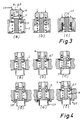
- Figure 3 a-c are sectional views illustrating the functioning of the earwax trap, and
- Figure 4 a-f are sectional views of various possible practical variations of an earwax trap according to said first embodiment, and
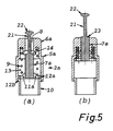
- Figure 5 a, b are sectional views showing an earwax trap according to a second embodiment of the present invention in operating and wax-removal positions respectively.
- Figure 1 shows an
insertion portion 1 of a hearing-aid apparatus, of which only the components relevant to the present invention are shown, i.e. - said
insertion portion 1, - a connecting
piece 2 constituting an acoustical connection through the wall of the tip of saidinsertion portion 1, - an electro-acoustical transducer or
receiver 3 adapted to generate sound in response to electrical signals from a microphone and amplifier (not shown) associated with or constituting part of the hearing-aid apparatus, and - a connecting
tube 4 constituting an acoustical connection from thereceiver 3 to theconnection piece 2. - Apart from serving as an acoustical conductor through the wall of the
insertion portion 1, the connectingpiece 2 is also adapted to prevent earwax from the user's external auditory meatus from entering and eventually blocking the acoustical conduit leading from thereceiver 3 to the outside of theinsertion portion 1, in a manner to be explained in more detail below. For this reason, the connectingpiece 2 is also designated "earwax trap", which designation will be used in the remainder of the present specification. - Referring now to Figure 2, the components of the
earwax trap 2 of direct relevance to the present invention are - a
housing 5 adapted to be secured in the wall of the tip of theinsertion portion 1 in the manner shown in Figure 1, or - alternatively - to constitute a part of said wall, - an
earwax collector 6 slideably supported in thehousing 5 between the normal operative position shown in Figure 2 and a wax-removal position shown in Figure 3c, and - an
earwax ejector 7, the cross-sectional shape of which corresponds at least roughly to the cross-sectional shape of aduct 8 formed and oriented in the earwax collector in such a manner, that when theearwax collector 6 is moved from the operating position shown in Figure 2 to the wax-removal position shown in Figure 3c, theduct 8 will be substantially fully occupied by and slideably receive the end portion of theearwax ejector 7, while - a
helical compression spring 9 constantly urges theearwax collector 6 towards the operating position shown in Figure 2. - The sound-transmission path through the
earwax trap 2 with theearwax collector 6 in the operating position shown in Figure 2 consists of - the space inside a
tube connector 10 adapted to be connected with the connectingtube 4 shown in figure 1, - at least one
aperture 11 formed in acollar 12 surrounding and supporting theearwax ejector 7, - a
space 13 surrounding theejector 7 and surrounded by thehousing 5, - an
annular gap 14 between the tip of theejector 7 and the adjacent part of thecollector 6 surrounding theduct 8, and - the
duct 8 itself. - Figure 3a-c shows how a lump of
earwax 15 having collected in theearwax collector 6 is removed by simply pushing theearwax collector 6 into thehousing 5 against the action of thespring 9, the force being represented byarrows 16 and suitably exerted by pressing two adjacent fingers onto thecollector 6. - Figure 3a shows the situation in the operating position shown also in Figure 2, whereas Figure 3b shows an intermediate situation, in which the
collector 6 is partly depressed, and Figure 3c shows the wax-removal position, in which the lump ofearwax 15 lies freely accessible on the tip of theejector 7 and can be removed without difficulty, such as by wiping it off with a piece of tissue or flicking it away with a finger. - Figures 4 a-f illustrate various possibilities in the practical realization of the present invention. Thus, in Figure 4a, the
housing 5 shown in Figure 2 is replaced by the adjacent portion of the wall of theinsertion portion 1, Figure 4b shows an arrangement in which thetube connector 10 shown in Figure 2 is replaced by a projecting flange on said wall and the outer limit for the movement of theearwax collector 6 is defined by alocking ring 17 inserted in said wall, Figure 4c shows a similar arrangement but with anejector 7 in the form of a separate part, Figure 4d shows an arrangement corresponding to that of Figure 2, inserted against aflange 18 formed in said wall, Figure 4e shows an arrangement with atube connector 19 in the form of a separate part, and Figure 4f shows an arrangement, in which only four parts are inserted in a passage through said wall, i.e. - a combination 20 comprising both a tube connector and an earwax ejector,
- a
spring 9, - an
earwax collector 6, and - a
locking ring 17. - It will be obvious to persons skilled in this art that the present invention may also be realized otherwise than shown. in the drawing and explained above. Thus, an
earwax collector 6 may comprise more than oneduct 8, each adapted to cooperate with itsown ejector 7. Further, the earwax trap need not necessarily be rotationally symmetrical as indicated in Figure 2, but may be square, rectangular, or otherwise shaped as seen in cross section in a plane at right angles to the plane of the drawing in Figure 2. The requisite relative movement between theearwax collector 6 and theearwax ejector 7 may also be achieved otherwise than shown and explained; thus, thecollector 6 may be arranged stationary with respect to theinsertion portion 1 and theejector 7 moveable, or both components may be moveable in opposite directions. The essential requirement is, of course, that the transition between an operating position corresponding to that shown in Figure 2 and wax-removal position corresponding to that shown in Figure 3c always proceeds with the relative movement between thecollector 6 andejector 7 being such, that the latter moves towards the outside of theinsertion portion 1, i.e. in a direction opposite the direction towards thereceiver 3. - In the embodiment shown in Figure 5, the
earwax collector 6a is an integral part of thehousing 5a, while theearwax ejector 7a is slidingly supported inside thehousing 5a guided by theflange 12a, the latter being constantly urged in the downward (i.e. in operation inward) direction by thespring 9. To make it possible to move theearwax ejector 7a to the wax-removal position shown in Figure 5b, athin stem 21 with aknob 22 on its free end is formed integral with theejector 7a. Any earwax (not shown) will collect on ashoulder 23 at the transition from theejector 7a proper to thestem 21, and can easily be wiped off as described above with reference to Figure 3a.Apertures 11a in thecollar 12a allow the passage of sound coming through the ample clearance between thestem 21 and the walls of theduct 8, and acollar 12b on thetube connector 10 connects the latter to thehousing 5a. - The earwax trap according to the present invention may be manufactured from any suitable material known to persons skilled in this art. Thus, the
collectors ejectors spring 9 may suitably be made from spring steel. If for some reason it is considered undesirable to have metal components in the earwax trap, thespring 9 may be replaced by an elastic rubber bellows or the like placed close to the inside wall of thehousing 5 or the corresponding part of theinsertion portion 1. - In normal operation, any earwax collecting in the
duct 8 can be removed from time to time by operating the trap in the manner described above. After prolonged periods of time, however, small amounts of earwax may have crept into thespace 13, and for this reason it is desirable to make it possible to dismantle the trap or remove it bodily from theinsertion portion 1. Persons skilled in this art will be able to devise methods of achieving this effect, not least after having seen Figures 4a-f. - The present invention is primarily intended for use with hearing-aid apparatus of the so-called in-the-ear (ITE) type, but may be used with the same effect with other types of hearing-aid apparatus, provided that these are adapted to deliver an acoustical signal into the external auditory meatus of the user. In this manner, the customary use of pipe cleaners and the like may be dispensed with.
-
- 1
- insertion portion
- 2, 2a
- connecting piece/ earwax trap
- 3
- electro-acoustical transducer/receiver
- 4
- connecting tube
- 5, 5a
- housing
- 6, 6a
- earwax collector
- 7
- earwax ejector
- 8
- duct
- 9
- spring
- 10
- tube connector
- 11, 11a
- aperture
- 12, 12a, 12b
- collar
- 13
- space
- 14
- annular gap
- 15
- earwax
- 16
- arrow
- 17
- locking ring
- 18
- flange
- 19
- tube connector
- 20
- combination
Claims (7)
- An earwax trap for use with hearing-aid apparatus and of the kind comprisinga) in a first part (6, 6a) a space (8) adapted to connect acoustically an interior part (3) of said hearing-aid apparatus with the external auditory meatus of the user's ear, andb) means (7, 7a) to prevent earwax having entered said space (8) from leaving same towards said interior part (3),characterized in that said leaving-preventing means comprise at least one piston- or plug-shaped member (7, 7a), which is adapted by relative movement between itself and the first part (6, 6a) containing said space (8) to enter said space (8) in a first direction away from said interior part (3) of said hearing-aid apparatus, and to leave said space (8) in the opposite direction and thus re-establish the acoustic connection between said interior part (3) and said space (8).
- A trap according to claim 1, characterized ina) that elastic means (9) are provided to urge said plug-shaped member (7, 7a) towards a position relative to said first part (6, 6a) containing said space (8), in which the plug-shaped member does not obstruct the acoustic communication between said interior part (3) and said external auditory meatus, andb) that the arrangement is such that said relative movement (mentioned in claim 1) may be caused by manually influencing (22, 16) said piston- or plug-shaped member (7a) and/or said first part (6) containing said space (8) or parts connected thereto, and that said relative position (mentioned in a above) is resumed when said manual influence ceases.
- A trap according to claim 2, characterized in that said plug-shaped member (7) is adapted to be stationary relative to the housing (5) of the trap (2), and that said first part (6) containing said space (8) is adapted to be moved relative thereto by being pushed into said housing (5).
- A trap according to claim 2, characterized in that said first part (6a) containing said space (8) is adapted to be stationary relative to the housing (5a) of the trap (2), and that said plug-shaped member (7a) is adapted to be moved relative thereto by being pulled out of said housing (5a), for this purpose comprising an externally accessible extension (21,22) extending outwardly with ample clearance through said space (8).
- A trap according to any one or any of the claims 1-4, characterized in that it is adapted to be inserted into the wall of an insertion portion (1) of a hearing-aid apparatus, said insertion portion (1) being adapted to be inserted into the external auditory meatus of the user's ear.
- A trap according to any one or any of the claims 1-4, characterized in that it is at least partly integral with the wall of an insertion portion (1) of a hearing-aid apparatus, said insertion portion (1) being adapted to be inserted into the external auditory meatus of the user's ear.
- A hearing-aid apparatus with an earwax trap (2) of the kind comprisinga) in a first part (6, 6a) a space (8) adapted to communicate acoustically an interior part (3) of said hearing-aid apparatus with the external auditory meatus of the user's ear, andb) means (7, 7a) to prevent earwax having entered said space (8) from leaving same towards said interior part (3),characterized in that said earwax trap (2) exhibits the features set forth in any one or any of the claims 1-6.
Priority Applications (1)
| Application Number | Priority Date | Filing Date | Title |
|---|---|---|---|
| AT91905011T ATE97291T1 (en) | 1990-02-26 | 1991-02-20 | CERUME TRAP FOR HEARING AID AND HEARING AID WITH LIKE. |
Applications Claiming Priority (2)
| Application Number | Priority Date | Filing Date | Title |
|---|---|---|---|
| DK049990A DK165096C (en) | 1990-02-26 | 1990-02-26 | OVERSEAS FIELDS FOR USE WITH HEARING DEVICES AND APPLICATION OF SUCH ANNOUNCING FIELD IN A HEARING DEVICE. |
| DK499/90 | 1990-02-26 |
Publications (2)
| Publication Number | Publication Date |
|---|---|
| EP0518906A1 EP0518906A1 (en) | 1992-12-23 |
| EP0518906B1 true EP0518906B1 (en) | 1993-11-10 |
Family
ID=8094260
Family Applications (1)
| Application Number | Title | Priority Date | Filing Date |
|---|---|---|---|
| EP91905011A Expired - Lifetime EP0518906B1 (en) | 1990-02-26 | 1991-02-20 | Earwax trap for use with hearing-aid apparatus, and hearing-aid apparatus with such a trap |
Country Status (10)
| Country | Link |
|---|---|
| US (1) | US5293008A (en) |
| EP (1) | EP0518906B1 (en) |
| JP (1) | JP2935747B2 (en) |
| AU (1) | AU7337391A (en) |
| CH (1) | CH692886A5 (en) |
| DE (1) | DE69100628T2 (en) |
| DK (1) | DK165096C (en) |
| ES (1) | ES2048589T3 (en) |
| NO (1) | NO306438B1 (en) |
| WO (1) | WO1991013525A1 (en) |
Families Citing this family (22)
| Publication number | Priority date | Publication date | Assignee | Title |
|---|---|---|---|---|
| US5898972A (en) * | 1996-09-19 | 1999-05-04 | Rademacher; Steven T. | Tool for removing debris from a hearing aid |
| US5982908A (en) * | 1997-12-22 | 1999-11-09 | Bauman; Natan | Ear wax collection device for a hearing aid |
| US6134333A (en) * | 1998-03-17 | 2000-10-17 | Sonic Innovations, Inc. | Disposable oleophobic and hydrophobic barrier for a hearing aid |
| US6105713A (en) * | 1998-09-17 | 2000-08-22 | Sonic Innovations, Inc. | Cover movable by rotation forming a cerumen barrier in a hearing aid |
| US6359993B2 (en) | 1999-01-15 | 2002-03-19 | Sonic Innovations | Conformal tip for a hearing aid with integrated vent and retrieval cord |
| US6135235A (en) * | 1999-04-06 | 2000-10-24 | Sonic Innovations, Inc. | Self-cleaning cerumen guard for a hearing device |
| AU4853000A (en) * | 1999-05-24 | 2000-12-12 | Sonic Innovations, Inc. | Combined receiver suspension and cerumen guard device for an in-the-canal hearing aid |
| US6179085B1 (en) | 1999-09-30 | 2001-01-30 | Sonic Innovations | Retention and extraction device for a hearing aid |
| US6532295B1 (en) | 1999-12-10 | 2003-03-11 | Sonic Innovations, Inc. | Method for fitting a universal hearing device shell and conformal tip in an ear canal |
| US6319020B1 (en) | 1999-12-10 | 2001-11-20 | Sonic Innovations, Inc. | Programming connector for hearing devices |
| US6456720B1 (en) | 1999-12-10 | 2002-09-24 | Sonic Innovations | Flexible circuit board assembly for a hearing aid |
| US6459800B1 (en) | 2000-07-11 | 2002-10-01 | Sonic Innovations, Inc. | Modular hearing device receiver suspension |
| WO2003027231A2 (en) * | 2001-09-04 | 2003-04-03 | Bristol-Myers Squibb Company | Polynucleotide encoding adapter protein, pmn29 |
| CN100531451C (en) * | 2002-02-07 | 2009-08-19 | 奥迪康有限公司 | Filter manipulator |
| USD525617S1 (en) | 2005-07-22 | 2006-07-25 | Intricon Corporation | Over the ear headset |
| US20080264428A1 (en) * | 2007-04-30 | 2008-10-30 | Purcell Ricky W | Self-fitting device for location in an ear canal |
| US7886745B2 (en) * | 2008-06-30 | 2011-02-15 | Kimberly-Clark Worldwide, Inc. | Self-fitting device for location in an ear canal |
| US7913696B2 (en) * | 2008-06-30 | 2011-03-29 | Kimberly-Clark Worldwide Inc. | Self-fitting device for location in an ear canal |
| US9629575B2 (en) * | 2014-12-30 | 2017-04-25 | Natus Medical Incorporated | Filter device and method of manufacturing a filter device |
| US10462589B2 (en) * | 2015-09-24 | 2019-10-29 | Starkey Laboratories, Inc. | Elastomeric wax barrier for hearing aid acoustic port |
| WO2019105522A1 (en) * | 2017-11-28 | 2019-06-06 | Sonova Ag | Cerumen filter applicator |
| EP4270993B1 (en) * | 2022-04-28 | 2024-10-30 | Sonova AG | Hearing instrument |
Family Cites Families (3)
| Publication number | Priority date | Publication date | Assignee | Title |
|---|---|---|---|---|
| CA1221315A (en) * | 1984-10-19 | 1987-05-05 | William J. Gastmeier | Hearing aid wax guard |
| US4870689A (en) * | 1987-04-13 | 1989-09-26 | Beltone Electronics Corporation | Ear wax barrier for a hearing aid |
| US4953215A (en) * | 1989-10-05 | 1990-08-28 | Siemens Aktiengesellschaft | Arrangement to prevent the intrusion of foreign matter into an electro-acoustical transducer |
-
1990
- 1990-02-26 DK DK049990A patent/DK165096C/en not_active IP Right Cessation
-
1991
- 1991-02-20 EP EP91905011A patent/EP0518906B1/en not_active Expired - Lifetime
- 1991-02-20 CH CH03074/91A patent/CH692886A5/en not_active IP Right Cessation
- 1991-02-20 JP JP3504589A patent/JP2935747B2/en not_active Expired - Fee Related
- 1991-02-20 ES ES91905011T patent/ES2048589T3/en not_active Expired - Lifetime
- 1991-02-20 WO PCT/DK1991/000051 patent/WO1991013525A1/en not_active Ceased
- 1991-02-20 AU AU73373/91A patent/AU7337391A/en not_active Abandoned
- 1991-02-20 DE DE91905011T patent/DE69100628T2/en not_active Expired - Fee Related
- 1991-02-20 US US07/910,271 patent/US5293008A/en not_active Expired - Lifetime
-
1992
- 1992-08-13 NO NO923165A patent/NO306438B1/en not_active IP Right Cessation
Also Published As
| Publication number | Publication date |
|---|---|
| ES2048589T3 (en) | 1994-03-16 |
| JPH05504453A (en) | 1993-07-08 |
| DK165096C (en) | 1993-02-15 |
| JP2935747B2 (en) | 1999-08-16 |
| DK49990D0 (en) | 1990-02-26 |
| AU7337391A (en) | 1991-09-18 |
| US5293008A (en) | 1994-03-08 |
| DE69100628D1 (en) | 1993-12-16 |
| WO1991013525A1 (en) | 1991-09-05 |
| CH692886A5 (en) | 2002-11-29 |
| DK49990A (en) | 1991-08-27 |
| DE69100628T2 (en) | 1994-03-10 |
| DK165096B (en) | 1992-10-05 |
| EP0518906A1 (en) | 1992-12-23 |
| NO923165D0 (en) | 1992-08-13 |
| NO306438B1 (en) | 1999-11-01 |
| NO923165L (en) | 1992-08-13 |
Similar Documents
| Publication | Publication Date | Title |
|---|---|---|
| US5293008A (en) | Earwax trap for use with hearing-aid apparatus, and hearing-aid apparatus with such a trap | |
| US4800982A (en) | Cleanable in-the-ear electroacoustic transducer | |
| US5712918A (en) | Press-fit ear wax barrier | |
| EP0377074B1 (en) | Hearing aid transducer | |
| EP0517322A2 (en) | Hearing aid intended for being mounted within the ear canal | |
| US9088853B2 (en) | Receiver system for a hearing instrument | |
| US7471800B2 (en) | Wax barrier system | |
| US8542858B2 (en) | Hearing device with a space-saving arrangement of microphones and sound openings | |
| US20040165742A1 (en) | Canal hearing device with tubular insert | |
| US5982908A (en) | Ear wax collection device for a hearing aid | |
| KR20010022382A (en) | Acoustic coupler | |
| US7076074B2 (en) | Bearing of an electroacoustic miniature transducer in a device, particularly a hearing aid device, as well as an electroacoustic miniature transducer | |
| US8124900B2 (en) | Pushbutton for a hearing device | |
| US8498436B2 (en) | Hearing device with a conducting element, in particular a sound tube | |
| WO2009120148A1 (en) | Hearing aid and battery chamber housing of a hearing aid | |
| US8224008B2 (en) | Hearing apparatus with a moveable charging contact | |
| EP3718314B1 (en) | Cerumen protection plug | |
| US8477971B2 (en) | Hearing device with supporting hook recognition | |
| WO2000072632A2 (en) | Combined receiver suspension and cerumen guard device for an in-the-canal hearing aid | |
| JPH084796Y2 (en) | hearing aid | |
| KR101778017B1 (en) | Sound Collector Structure |
Legal Events
| Date | Code | Title | Description |
|---|---|---|---|
| PUAI | Public reference made under article 153(3) epc to a published international application that has entered the european phase |
Free format text: ORIGINAL CODE: 0009012 |
|
| 17P | Request for examination filed |
Effective date: 19920724 |
|
| AK | Designated contracting states |
Kind code of ref document: A1 Designated state(s): AT BE CH DE DK ES FR GB GR IT LI LU NL SE |
|
| 17Q | First examination report despatched |
Effective date: 19930422 |
|
| GRAA | (expected) grant |
Free format text: ORIGINAL CODE: 0009210 |
|
| AK | Designated contracting states |
Kind code of ref document: B1 Designated state(s): AT BE CH DE DK ES FR GB GR IT LI LU NL SE |
|
| PG25 | Lapsed in a contracting state [announced via postgrant information from national office to epo] |
Ref country code: GR Free format text: LAPSE BECAUSE OF FAILURE TO SUBMIT A TRANSLATION OF THE DESCRIPTION OR TO PAY THE FEE WITHIN THE PRESCRIBED TIME-LIMIT Effective date: 19931110 Ref country code: IT Free format text: LAPSE BECAUSE OF FAILURE TO SUBMIT A TRANSLATION OF THE DESCRIPTION OR TO PAY THE FEE WITHIN THE PRESCRIBED TIME-LIMIT;WARNING: LAPSES OF ITALIAN PATENTS WITH EFFECTIVE DATE BEFORE 2007 MAY HAVE OCCURRED AT ANY TIME BEFORE 2007. THE CORRECT EFFECTIVE DATE MAY BE DIFFERENT FROM THE ONE RECORDED. Effective date: 19931110 Ref country code: LI Effective date: 19931110 Ref country code: BE Effective date: 19931110 Ref country code: CH Effective date: 19931110 Ref country code: DK Effective date: 19931110 |
|
| REF | Corresponds to: |
Ref document number: 97291 Country of ref document: AT Date of ref document: 19931115 Kind code of ref document: T |
|
| REF | Corresponds to: |
Ref document number: 69100628 Country of ref document: DE Date of ref document: 19931216 |
|
| REG | Reference to a national code |
Ref country code: CH Ref legal event code: PL |
|
| PG25 | Lapsed in a contracting state [announced via postgrant information from national office to epo] |
Ref country code: LU Free format text: LAPSE BECAUSE OF NON-PAYMENT OF DUE FEES Effective date: 19940228 |
|
| ET | Fr: translation filed | ||
| REG | Reference to a national code |
Ref country code: ES Ref legal event code: FG2A Ref document number: 2048589 Country of ref document: ES Kind code of ref document: T3 |
|
| PGFP | Annual fee paid to national office [announced via postgrant information from national office to epo] |
Ref country code: DK Payment date: 19940331 Year of fee payment: 4 |
|
| PLBE | No opposition filed within time limit |
Free format text: ORIGINAL CODE: 0009261 |
|
| STAA | Information on the status of an ep patent application or granted ep patent |
Free format text: STATUS: NO OPPOSITION FILED WITHIN TIME LIMIT |
|
| 26N | No opposition filed | ||
| EAL | Se: european patent in force in sweden |
Ref document number: 91905011.2 |
|
| PG25 | Lapsed in a contracting state [announced via postgrant information from national office to epo] |
Ref country code: GB Effective date: 19950220 |
|
| GBPC | Gb: european patent ceased through non-payment of renewal fee |
Effective date: 19950220 |
|
| PGFP | Annual fee paid to national office [announced via postgrant information from national office to epo] |
Ref country code: AT Payment date: 20090225 Year of fee payment: 19 Ref country code: ES Payment date: 20090226 Year of fee payment: 19 |
|
| PGFP | Annual fee paid to national office [announced via postgrant information from national office to epo] |
Ref country code: DE Payment date: 20090226 Year of fee payment: 19 Ref country code: NL Payment date: 20090220 Year of fee payment: 19 |
|
| PGFP | Annual fee paid to national office [announced via postgrant information from national office to epo] |
Ref country code: SE Payment date: 20090223 Year of fee payment: 19 |
|
| PGFP | Annual fee paid to national office [announced via postgrant information from national office to epo] |
Ref country code: FR Payment date: 20090227 Year of fee payment: 19 |
|
| REG | Reference to a national code |
Ref country code: NL Ref legal event code: V1 Effective date: 20100901 |
|
| EUG | Se: european patent has lapsed | ||
| REG | Reference to a national code |
Ref country code: FR Ref legal event code: ST Effective date: 20101029 |
|
| PG25 | Lapsed in a contracting state [announced via postgrant information from national office to epo] |
Ref country code: AT Free format text: LAPSE BECAUSE OF NON-PAYMENT OF DUE FEES Effective date: 20100220 |
|
| PG25 | Lapsed in a contracting state [announced via postgrant information from national office to epo] |
Ref country code: FR Free format text: LAPSE BECAUSE OF NON-PAYMENT OF DUE FEES Effective date: 20100301 Ref country code: NL Free format text: LAPSE BECAUSE OF NON-PAYMENT OF DUE FEES Effective date: 20100901 |
|
| PG25 | Lapsed in a contracting state [announced via postgrant information from national office to epo] |
Ref country code: DE Free format text: LAPSE BECAUSE OF NON-PAYMENT OF DUE FEES Effective date: 20100901 |
|
| REG | Reference to a national code |
Ref country code: ES Ref legal event code: FD2A Effective date: 20110407 |
|
| PG25 | Lapsed in a contracting state [announced via postgrant information from national office to epo] |
Ref country code: ES Free format text: LAPSE BECAUSE OF NON-PAYMENT OF DUE FEES Effective date: 20110324 |
|
| PG25 | Lapsed in a contracting state [announced via postgrant information from national office to epo] |
Ref country code: ES Free format text: LAPSE BECAUSE OF NON-PAYMENT OF DUE FEES Effective date: 20100221 |
|
| PG25 | Lapsed in a contracting state [announced via postgrant information from national office to epo] |
Ref country code: SE Free format text: LAPSE BECAUSE OF NON-PAYMENT OF DUE FEES Effective date: 20100221 |