EP0518563B1 - Fastener driving device with sequential actuation trigger assembly - Google Patents
Fastener driving device with sequential actuation trigger assembly Download PDFInfo
- Publication number
- EP0518563B1 EP0518563B1 EP92305152A EP92305152A EP0518563B1 EP 0518563 B1 EP0518563 B1 EP 0518563B1 EP 92305152 A EP92305152 A EP 92305152A EP 92305152 A EP92305152 A EP 92305152A EP 0518563 B1 EP0518563 B1 EP 0518563B1
- Authority
- EP
- European Patent Office
- Prior art keywords
- movement
- slide
- actuating
- fastener driving
- trigger
- Prior art date
- Legal status (The legal status is an assumption and is not a legal conclusion. Google has not performed a legal analysis and makes no representation as to the accuracy of the status listed.)
- Expired - Lifetime
Links
Images

Classifications
-
- B—PERFORMING OPERATIONS; TRANSPORTING
- B25—HAND TOOLS; PORTABLE POWER-DRIVEN TOOLS; MANIPULATORS
- B25C—HAND-HELD NAILING OR STAPLING TOOLS; MANUALLY OPERATED PORTABLE STAPLING TOOLS
- B25C1/00—Hand-held nailing tools; Nail feeding devices
- B25C1/04—Hand-held nailing tools; Nail feeding devices operated by fluid pressure, e.g. by air pressure
- B25C1/047—Mechanical details
Definitions
- This invention relates to fastener driving devices and, more particularly, to portable power-actuated fastener driving devices.
- Power actuated fastener driving devices of the type herein contemplated are, for the most part, of the fluid pressure operated type, although solenoid operated devices and internal combustion operated devices are also contemplated.
- Most portable power actuated fastener driving devices are provided with an actuating mechanism which includes two components; one, a trigger member and two, a contact trip member. These members are interrelated by an enabling mechanism which causes an actuating member to be moved when both the contact trip and trigger members are moved from their normal inoperative positions into their operative positions.
- the contact trip member is moved from its normal inoperative position into its operative position by movement of the portable device into engagement with the workpiece.
- the trigger member is moved by a digital pressure by the operator.
- actuating mechanisms can be either of the sequential type or of the concomitant type.
- a sequential actuating mechanism requires the operator to move first the contact trip member into its operative position and then the trigger member into its operative position in order for the actuating member to be moved.
- the concomitant type is one in which the actuating member will move in response to the movement of both the contact trip and trigger member into their operative positions irrespective of the order in which they are moved therein.
- the present invention is particularly directed to the sequential type of actuating mechanisms.
- US-A-3 784 077 discloses a portable power actuated fastener driving device having a housing defining a drive track and a fastener magazine carried by the housing, wherein power control means including an actuating member is used to operate a fastener driving means having a fastener driving element carried by the housing for movement within the drive track.
- the power control means can be operated by way of a trigger member.
- the device also includes a work contact assembly for enabling operation of the device when in contact with a work piece.
- the device further has an enabling structure for allowing the required sequential operation, which structure has a pivot portion pivotally connected to an end portion of the actuating member and two arms extending in opposite directions from the pivot portion.
- One of the arms is arranged for contact by a work piece contact element of the work contact assembly, and the other arm is provided for contact by a pin formation on the trigger.
- the operating relationship between these elements of the device requires that the pivot portion is permanently pivotally mounted on the actuating member by way of a pivot pin.
- EP-A-0 203 620 discloses a portable power actuated fastener driving device having a power operated fastener driving means operable by means of a trigger-controlled power control means for driving a faster driving element along a drive track to impact on fasteners delivered to the drive track by way of a fastener magazine.
- the device also includes a work contact assembly for enabling operation of the device only when in contact with a work piece.
- the trigger assembly includes an operating lever which is biased into engagement with an actuating member of the device irrespective of whether the trigger assembly is to effect operation of the device and, further, the device has a mode of operation in which, once a fastener has been delivered by way of a sequential drive operation, continued operation of the trigger allows for delivery of further fasteners merely by operation of the work contact assembly.
- An object of the present invention is to provide a sequential trigger assembly which likewise will meet this criteria.
- a portable power actuated fastener driving device including a portable housing having means defining a drive track, power operated fastener driving means including a fastener driving element carried by said housing for movement within said drive track through successive cycles of operation each of which includes a fastener driving stroke and a return stroke, fastener magazine means carried by said housing for receiving a supply of fasteners and feeding successive fasteners into the drive track in a position to be driven into a workpiece during successive fastener driving strokes of said fastener driving means, power control means including an actuating member carried by said housing for movement from a normal inoperative position into an operative position for initiating the movement of said fastener driving means through a fastener driving stroke, a work contact assembly carried by said housing including a movable member mounted for movement from a normal inoperative position into an operative position in response to the movement of said device into co-operating engagement with a workpiece, a trigger member pivoted to said housing for manual movement from a normal
- the invention allows the provision of an actuating mechanism of the type described which is simple in construction, effective in operation and economical to manufacture.
- FIG. 1 a portable power operated fastener driving device, generally indicated at 10, which embodies the principles of the present invention.
- the power operated device illustrated is of the fluid pressure operated type and includes the usual portable housing, generally indicated at 12, which includes a handle grip portion 14 of hollow configuration which constitutes a reservoir for air under pressure coming from a source which is communicated therewith.
- the forward end of the grip portion intersects with a vertical housing portion 16.
- Mounted within the housing portion 16 is a cylindrical member 18 defining a cylindrical chamber within which a piston 20 is slidably sealingly mounted for movement from an upper position, as shown, through a drive stroke into a lowermost position and from the lowermost position through a return stroke back into its upper limiting position.
- a main valve is provided for controlling communication of the reservoir pressure to the upper end of the cylinder to effect the driving movement of the piston.
- the main valve 22 is pilot pressure operated and the pilot pressure chamber thereof is under the control of an actuating valve mechanism, generally indicated at 24.
- Means is provided within the housing 12 to effect the return stroke of the piston 20.
- such means may be in the form of a conventional plenum chamber return system such as disclosed in U.S. Patent No. 3,708,096, the disclosure of which is hereby incorporated into the present specification.
- a fastener driving element 26 is suitably connected with the piston 20 and is slidably mounted within a drive track 28 (see Figure 3) formed in a nosepiece assembly, generally indicated at 30, forming a fixed part of the housing 12.
- the nosepiece assembly 30 as illustrated includes a jam-clearing mechanism 32 similar to that disclosed in commonly assigned U.S. Patent No. 3,934,778, the disclosure of which is hereby incorporated by reference into the present specification.
- the jam-clearing mechanism 32 embodied in the nosepiece assembly is movable only when it is desired to clear the drive track of a jammed fastener.
- the nosepiece assembly including the jam-clearing mechanism 32 is operationally rigid. It will be understood that a fully rigid nosepiece assembly without a jam-clearing mechanism may be utilized if desired.
- a magazine assembly Fixed to the nosepiece assembly 30 is a magazine assembly, generally indicated at 34, which is operable to receive a supply of fasteners and to feed the leading fastener of the supply into the drive track to be driven therefrom by the fastener driving element.
- the present invention is more particularly concerned with an improved sequential actuating mechanism 36 for initiating the drive stroke of the fastener driving element 26.
- the actuating mechanism 36 includes essentially two manually operable assemblies, one of which is a trigger assembly, generally indicated at 38, and the other of which is a work-engaging or contacting assembly, generally indicated at 40.
- the work-engaging or contacting assembly may assume a variety of different configurations. However, a preferred construction is in accordance with the teachings contained in commonly assigned U.S. Patent No. 4,767,043, the disclosure of which is hereby incorporated by reference into the present specification.
- the assembly 40 includes a work-engaging member which is spring pressed as by spring 41 into a normal inoperative position extending below the end of the nosepiece assembly 30 and movable therefrom when the device is moved into cooperating relation with a workpiece into an operative position against the bias of the spring.
- the work-engaging assembly 40 includes a movable member 42 which is connected with the work-engaging member to move therewith so that it too moves between a normal inoperative position and an operative position.
- the valve-actuating mechanism 24 may likewise assume any desired configuration. However, as best shown in Figures 2 and 5, the mechanism 24 includes a valve housing 44 sealingly engaged within a recess 46 formed in the handle portion 14 of the housing 12. Mounted within the valve housing 44 is a tubular valve member 48. The valve member 48 is resiliently biased, as by a spring 49, into a normal inoperative position as shown in Figure 2 wherein a supply of air under pressure within the hollow handle portion 14 of the housing 12 is enabled to pass through an inlet opening 50 in the valve housing 44 and around the tubular valve member 48 through central openings 52 in the valve housing 44 and into a passage 54 which communicates with the pilot pressure chamber for the main valve 22.
- the main valve 22 When the pilot pressure chamber is under pressure, the main valve 22 is in a closed position as shown in Figure 1.
- the main valve 22 is pressure biased to move into an open position when the pressure in the pilot pressure chamber is relieved.
- the pilot pressure is relieved when the tubular valve member 48 moves from the inoperative position shown in Figure 2 into the operative position shown in Figure 5. This movement is under the control of an actuating member 56 which is biased by the spring 49 into a normally inoperative position as shown in Figure 2.
- the actuating member 56 is mounted for rectilinear movement in a direction toward and away from the trigger assembly 38 which is disposed therebelow within a valve housing section 58 which is mounted within the lower portion of the valve housing in such a way as to provide a vent to atmosphere around the periphery of the valve housing section 58.
- the actuating member 56 includes a slide- engaging portion which extends exteriorly of the housing section 58.
- an O-ring seal 60 serves to peripherally seal the actuating member 56 within an opening 62 leading to a control chamber 64 formed in the housing section 158.
- the tubular valve member 48 includes a lower portion having a peripheral seal 66 is mounted within the control chamber 64 and which serves to trap air under pressure within the control chamber 64 entering through the inlet 50 and through the hollow interior of the valve member 48. Pressure from the supply within the hollow handle portion 14 of the housing 12 thus works with the bias of the spring 49 to maintain the tubular valve member 48 in the inoperative position shown in Figure 2.
- a central O-ring seal 68 engages an annular valve seat 70 on the valve housing to prevent the pressure within the passage 54 and openings 52 from escaping the atmosphere beyond the periphery of the housing section 58.
- the upward movement of the actuating member 56 carries with it a second O-ring seal 72 on the upper portion of the actuating member which engages within the hollow interior of the tubular valve member 48 and seals off the pressure supply to the control chamber 64.
- the downward movement of tubular valve member 48 carries with it an upper O-ring seal 74 on the valve member 48 into sealing engagement with the adjacent interior of the valve housing 44. In this way, the supply pressure acts upon the tubular valve member 48 to maintain it in its operative position. At the same time, the pressure within passage 54 and openings 52 is relieved through the vent past the periphery of housing section 58.
- the spring 49 is stressed and serves to bias the actuating member downwardly for movement out of its operative position back into the inoperative position thereof shown in Figure 2. This allows supply pressure to enter the control chamber 64 to return the valve member into its inoperative position wherein pilot pressure passage 54 is pressurized and the main valve 22 is moved into its closed position to permit the piston 20 and fastener driving element 26 to move through a return stroke.
- the trigger assembly 38 includes a trigger member 76 which is of generally U-shaped cross-sectional configuration and includes forwardly extending mounting portions through which a pivot pin 78 is engaged so as to mount the trigger member 76 for pivotal movement about the axis of the pivot pin 78 between a normal inoperative position as shown in Figure 2 and an operative position as shown in Figure 5.
- the trigger member 76 is biased into its normal inoperative position by a spring 80 which is connected between the valve housing section 58 and the upper portion of the trigger member 76.
- the trigger member 76 also includes a generally L-shaped rear wall portion which serves to define a rearward chamber therein within which is mounted a slide member 82 for rectilinear movement with respect to the trigger member 76.
- the slide member 82 includes a counterbore in one end thereof within which one end of a compression coil spring 84 is mounted, the opposite end of which engages a leg of the L-shaped wall portion.
- the coil spring 84 thus serves to resiliently bias the slide member 82 into an abutting position with respect to the actuating member 56, which abutting position is shown in Figure 2.
- a slide moving member 86 is pivotally mounted on the trigger member 76 in a position forwardly of the slide member 82 by a shaft 88 providing a pivotal axis which is parallel with the pivotal axis of the trigger member 76.
- the slide-moving member 86 includes a central hub portion which is journalled on the shaft 88 and a first lever arm 90 extending outwardly from the pivotal axis.
- the outwardly extending end of the lever arm 90 is formed into a slide surface which is adapted to engage a cooperating slide surface 92 on the lower forward portion of the slide member 82.
- the slide surface 92 of the slide member 82 terminates upwardly in an abutment surface 94 which is engaged by the lever arm 90 of the slide moving member 86.
- a torsional coil spring 96 is positioned around the hub portion of the slide moving member 86 and has one end anchored to the trigger member 76 and an opposite end anchored to a laterally extending portion of a second lever arm 98 of the slide moving member 86 which extends outwardly from the pivotal axis thereof. It will be understood that the strength of the torsional spring 96 in relation to the strength of the coil spring 84 is such as to cause the slide moving member 86 to pivot into a first position, such as shown in Figure 2, wherein the engagement of the first lever arm 90 thereof with the sliding surface 92 serves to move the slide moving member 86 into a non-abutting position wherein the abutment surface 94 is engaged by lever arm 90.
- the laterally extending portion of the second lever arm 98 is disposed in a position to be engaged and moved into a second position as shown in Figure 5 by the upper end of the movable member 42 of the work contacting assembly 40 when the latter is moved from its inoperative into its operative position.
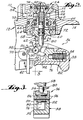
- Figure 2 illustrates the position of the parts of the actuating mechanism 36 in its normal at- rest condition preparatory to use.
- the movable member 42 of the work contacting assembly 40 is maintained by spring 41 in its normal operative position and that spring serves to bias the actuating member in its normal inoperative position.
- spring 80 serves to bias the trigger member 76 into its normal inoperative position.
- the torsion spring 96 serves to bias the slide moving member 86 into its first position which retains the slide member 82 in its non-abutting position against the bias of spring 84.
- the actuating mechanism 36 is operable to actuate the main valve 22 only when a predetermined sequence of manual actuating procedural steps are performed by the operator.
- the first of these actuating procedural steps is for the operator to move the device 10 into cooperating relation with the workpiece which is to receive the fastener.
- the movable member 42 moves from the normal inoperative position thereof into the operative position, which is shown in Figure 4.
- the upper end of the movable member 42 engages the laterally extending portion of the second lever arm 98 of the slide moving member 86 and serves to move the slide moving member 86, in a clockwise direction as viewed in Figure 4, from its first position, as shown in Figure 2, into the second position, which is shown in Figure 4.
- the first lever arm 90 also moves in a clockwise direction as viewed in Figure 4 along the sliding surface 92 of the slide member 82 to allow it to be moved from its non-abutting position, as shown in Figure 2, into its abutting position, as shown in Figure 4, under the bias of the spring 84.
- the direction of the sliding rectilinear movement of the slide member 82 under the bias of spring 84 when in motion transmitting relation with the slide moving member 86 is in a direction generally transverse to the rectilinear direction of movement of the actuating member 56.
- the central portion of the trigger member 76 moves in a direction which is generally the same as the direction of movement of the actuating member 56.
- the next manual actuating procedural step in the sequential actuation is for the operator to digitally effect a movement of the trigger member 76 from its normal inoperative position, as shown in Figure 2, into the operative position thereof, such as shown in Figure 5.
- the slide member 82 will engage the lower end of the actuating member 56 and move the same from its inoperative position into the operative position thereof, as shown in Figure 5.
- the drive stroke of the piston 20 and fastener driving element 26 causes the device 10 to rebound from the workpiece which has the effect of moving the movable member 42 from its operative position into its inoperative position.
- This movement allows the torsional spring 96 to pivot the slide moving member 86 back into its first position which has the effect of moving the slide member 82 back into its non-abutting position thus allowing the actuating member 56 to return to its inoperative position even though the operator may still be retaining the trigger member 76 in its operative position.
- Figure 6 illustrates the position which the parts will assume in the event that the trigger member 76 is moved initially from its inoperative position into its operative position when the device 10 has not been moved into co-operating relationship with the workpiece so that the movable member 42 is in the inoperative position thereof as shown in Figure 6.
- the slide member 82 remains in its non-abutting position and simply moves with the trigger member 76 along a path which is alongside the actuating member 56 and out of engagement and motion transmitting relation with respect thereto.
- actuation will not occur.
- the trigger assembly 38 of the present invention enables the manufacturer to replace the sequential trigger assembly 38 of the present invention with a trigger assembly of the concomitant type in which there is a single lever arm carried by the trigger member or vice versa.
Landscapes
- Physics & Mathematics (AREA)
- Fluid Mechanics (AREA)
- Engineering & Computer Science (AREA)
- Mechanical Engineering (AREA)
- Portable Nailing Machines And Staplers (AREA)
Abstract
Description
- This invention relates to fastener driving devices and, more particularly, to portable power-actuated fastener driving devices.
- Power actuated fastener driving devices of the type herein contemplated are, for the most part, of the fluid pressure operated type, although solenoid operated devices and internal combustion operated devices are also contemplated. Most portable power actuated fastener driving devices are provided with an actuating mechanism which includes two components; one, a trigger member and two, a contact trip member. These members are interrelated by an enabling mechanism which causes an actuating member to be moved when both the contact trip and trigger members are moved from their normal inoperative positions into their operative positions. The contact trip member is moved from its normal inoperative position into its operative position by movement of the portable device into engagement with the workpiece. The trigger member is moved by a digital pressure by the operator. It is well known that actuating mechanisms can be either of the sequential type or of the concomitant type. A sequential actuating mechanism requires the operator to move first the contact trip member into its operative position and then the trigger member into its operative position in order for the actuating member to be moved. The concomitant type is one in which the actuating member will move in response to the movement of both the contact trip and trigger member into their operative positions irrespective of the order in which they are moved therein. The present invention is particularly directed to the sequential type of actuating mechanisms.
- An example of a sequential type actuating mechanism is known from US-A-3 784 077 which discloses a portable power actuated fastener driving device having a housing defining a drive track and a fastener magazine carried by the housing, wherein power control means including an actuating member is used to operate a fastener driving means having a fastener driving element carried by the housing for movement within the drive track. The power control means can be operated by way of a trigger member. The device also includes a work contact assembly for enabling operation of the device when in contact with a work piece. The device further has an enabling structure for allowing the required sequential operation, which structure has a pivot portion pivotally connected to an end portion of the actuating member and two arms extending in opposite directions from the pivot portion. One of the arms is arranged for contact by a work piece contact element of the work contact assembly, and the other arm is provided for contact by a pin formation on the trigger. The operating relationship between these elements of the device requires that the pivot portion is permanently pivotally mounted on the actuating member by way of a pivot pin.
- Further, EP-A-0 203 620 discloses a portable power actuated fastener driving device having a power operated fastener driving means operable by means of a trigger-controlled power control means for driving a faster driving element along a drive track to impact on fasteners delivered to the drive track by way of a fastener magazine. The device also includes a work contact assembly for enabling operation of the device only when in contact with a work piece. The trigger assembly includes an operating lever which is biased into engagement with an actuating member of the device irrespective of whether the trigger assembly is to effect operation of the device and, further, the device has a mode of operation in which, once a fastener has been delivered by way of a sequential drive operation, continued operation of the trigger allows for delivery of further fasteners merely by operation of the work contact assembly.
- It is sometimes desirable to be able to equip a given fastener driving device alternatively either with a sequential actuating arrangement or a concomitant actuating arrangement. The present invention is based upon the concept that this desirability can best be accomplished when the two alternative mechanisms can be simply substituted for one another at the factory in a manner which permits substitution of trigger mechanisms without the necessity to modify or provide special connections with the movable member of the contact trip assembly or the actuating member of the actuating valve assembly. Trigger assemblies of the concomitant type are available which meet this criteria.
- An object of the present invention is to provide a sequential trigger assembly which likewise will meet this criteria.
- In accordance with the present invention, there is provided a portable power actuated fastener driving device including
a portable housing having means defining a drive track,
power operated fastener driving means including a fastener driving element carried by said housing for movement within said drive track through successive cycles of operation each of which includes a fastener driving stroke and a return stroke,
fastener magazine means carried by said housing for receiving a supply of fasteners and feeding successive fasteners into the drive track in a position to be driven into a workpiece during successive fastener driving strokes of said fastener driving means, power control means including an actuating member carried by said housing for movement from a normal inoperative position into an operative position for initiating the movement of said fastener driving means through a fastener driving stroke,
a work contact assembly carried by said housing including a movable member mounted for movement from a normal inoperative position into an operative position in response to the movement of said device into co-operating engagement with a workpiece,
a trigger member pivoted to said housing for manual movement from a normal inoperative position into an operative position, characterized by,
a movable abutment member mounted on said trigger member for movement with respect thereto between an abutment position with respect to said actuating member wherein said movable abutment member is disposed to engage said actuating member in motion transmitting relation to move the same from the inoperative position thereof to the operative position thereof in response to the manual movement of said trigger member from the inoperative position thereof to the operative position thereof and a non-abutment position with respect to said actuating member wherein said movable abutment member is disposed to be out of engagement with said actuating member so that said actuating member remains in the inoperative position thereof in response to the manual movement of said trigger member from the inoperative position to the operative position thereof,
first spring means operatively associated with said movable abutment member for resiliently biasing said movable abutment member toward the abutting position thereof,
an abutment moving member mounted on said trigger member for movement with respect thereto between first and second positions,
second spring means operatively associated with said abutment moving member for resiliently biasing said abutment moving member into the first position thereof,
and means for providing a motion transmitting relationship between said abutment moving member and said movable member and between said abutment moving member and said movable abutment member for causing said movable abutment member to be in the non-abutting position thereof when said abutment moving member is in said first position so that when said trigger member is manually moved from the inoperative position to the operative position thereof without the device being in co-operating relation with a workpiece said actuating member remains in the inoperative position thereof and enabling said movable abutment member to be biased into the abutting position thereof by said first spring means when said movable member is moved from the inoperative position into the operative position thereof so that a manual movement of said trigger member thereafter into the operative position thereof causes said movable abutment member to move said actuating member into the operating position thereof, and causing said actuating member to remain in the inoperative position thereof when said movable member is moved from the inoperative position to the operative position thereof after said trigger member has been moved into the operative position thereof. - As specifically illustrated hereafter, the invention allows the provision of an actuating mechanism of the type described which is simple in construction, effective in operation and economical to manufacture.
- These and other objects of the present invention will become more apparent during the course of the following detailed description and appended claims.
- The invention may best be understood with reference to the accompanying drawings wherein an illustrative embodiment is shown.
-
- Figure 1 is a side elevational view, with parts broken away for purposes of clear illustration, of a portable power operated fastener driving device embodying the principles of the present invention;
- Figure 2 is an enlarged fragmentary vertical sectional view showing the improved actuating mechanism of the present invention with the parts in their inoperative position;
- Figure 3 is a sectional view taken along the line 3-3 of Figure 2;
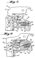
- Figure 4 is a fragmentary elevational view of the actuating mechanism with parts broken away for purposes of clear illustration showing the parts in the position assumed following the movement of the device into cooperating relation with a workpiece;
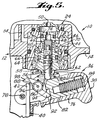
- Figure 5 is a view similar to Figure 2 showing the position of the parts after sequential actuation; and
- Figure 6 is a view similar to Figure 4 showing the position of the parts when the trigger is actuated but the device has not been moved into cooperating relation with a workpiece.
- Referring now more particularly to the drawings, there is shown in Figure 1 thereof a portable power operated fastener driving device, generally indicated at 10, which embodies the principles of the present invention. The power operated device illustrated is of the fluid pressure operated type and includes the usual portable housing, generally indicated at 12, which includes a
handle grip portion 14 of hollow configuration which constitutes a reservoir for air under pressure coming from a source which is communicated therewith. The forward end of the grip portion intersects with avertical housing portion 16. Mounted within thehousing portion 16 is acylindrical member 18 defining a cylindrical chamber within which apiston 20 is slidably sealingly mounted for movement from an upper position, as shown, through a drive stroke into a lowermost position and from the lowermost position through a return stroke back into its upper limiting position. A main valve, generally indicated at 22, is provided for controlling communication of the reservoir pressure to the upper end of the cylinder to effect the driving movement of the piston. Themain valve 22 is pilot pressure operated and the pilot pressure chamber thereof is under the control of an actuating valve mechanism, generally indicated at 24. Means is provided within thehousing 12 to effect the return stroke of thepiston 20. For example, such means may be in the form of a conventional plenum chamber return system such as disclosed in U.S. Patent No. 3,708,096, the disclosure of which is hereby incorporated into the present specification. - In accordance with the usual practice, a
fastener driving element 26 is suitably connected with thepiston 20 and is slidably mounted within a drive track 28 (see Figure 3) formed in a nosepiece assembly, generally indicated at 30, forming a fixed part of thehousing 12. The nosepiece assembly 30 as illustrated includes a jam-clearing mechanism 32 similar to that disclosed in commonly assigned U.S. Patent No. 3,934,778, the disclosure of which is hereby incorporated by reference into the present specification. The jam-clearing mechanism 32 embodied in the nosepiece assembly is movable only when it is desired to clear the drive track of a jammed fastener. In normal operation, the nosepiece assembly including the jam-clearing mechanism 32 is operationally rigid. It will be understood that a fully rigid nosepiece assembly without a jam-clearing mechanism may be utilized if desired. - Fixed to the nosepiece assembly 30 is a magazine assembly, generally indicated at 34, which is operable to receive a supply of fasteners and to feed the leading fastener of the supply into the drive track to be driven therefrom by the fastener driving element.
- The present invention is more particularly concerned with an improved
sequential actuating mechanism 36 for initiating the drive stroke of thefastener driving element 26. Theactuating mechanism 36 includes essentially two manually operable assemblies, one of which is a trigger assembly, generally indicated at 38, and the other of which is a work-engaging or contacting assembly, generally indicated at 40. The work-engaging or contacting assembly may assume a variety of different configurations. However, a preferred construction is in accordance with the teachings contained in commonly assigned U.S. Patent No. 4,767,043, the disclosure of which is hereby incorporated by reference into the present specification. As shown, theassembly 40 includes a work-engaging member which is spring pressed as by spring 41 into a normal inoperative position extending below the end of the nosepiece assembly 30 and movable therefrom when the device is moved into cooperating relation with a workpiece into an operative position against the bias of the spring. The work-engaging assembly 40 includes amovable member 42 which is connected with the work-engaging member to move therewith so that it too moves between a normal inoperative position and an operative position. - The valve-
actuating mechanism 24 may likewise assume any desired configuration. However, as best shown in Figures 2 and 5, themechanism 24 includes avalve housing 44 sealingly engaged within arecess 46 formed in thehandle portion 14 of thehousing 12. Mounted within thevalve housing 44 is atubular valve member 48. Thevalve member 48 is resiliently biased, as by aspring 49, into a normal inoperative position as shown in Figure 2 wherein a supply of air under pressure within thehollow handle portion 14 of thehousing 12 is enabled to pass through aninlet opening 50 in thevalve housing 44 and around thetubular valve member 48 throughcentral openings 52 in thevalve housing 44 and into apassage 54 which communicates with the pilot pressure chamber for themain valve 22. When the pilot pressure chamber is under pressure, themain valve 22 is in a closed position as shown in Figure 1. Themain valve 22 is pressure biased to move into an open position when the pressure in the pilot pressure chamber is relieved. The pilot pressure is relieved when thetubular valve member 48 moves from the inoperative position shown in Figure 2 into the operative position shown in Figure 5. This movement is under the control of an actuatingmember 56 which is biased by thespring 49 into a normally inoperative position as shown in Figure 2. The actuatingmember 56 is mounted for rectilinear movement in a direction toward and away from thetrigger assembly 38 which is disposed therebelow within avalve housing section 58 which is mounted within the lower portion of the valve housing in such a way as to provide a vent to atmosphere around the periphery of thevalve housing section 58. As shown, the actuatingmember 56 includes a slide- engaging portion which extends exteriorly of thehousing section 58. In the normal inoperative position shown in Figure 2, an O-ring seal 60 serves to peripherally seal the actuatingmember 56 within anopening 62 leading to acontrol chamber 64 formed in the housing section 158. - As shown, the
tubular valve member 48 includes a lower portion having aperipheral seal 66 is mounted within thecontrol chamber 64 and which serves to trap air under pressure within thecontrol chamber 64 entering through theinlet 50 and through the hollow interior of thevalve member 48. Pressure from the supply within thehollow handle portion 14 of thehousing 12 thus works with the bias of thespring 49 to maintain thetubular valve member 48 in the inoperative position shown in Figure 2. In this position, a central O-ring seal 68 engages anannular valve seat 70 on the valve housing to prevent the pressure within thepassage 54 andopenings 52 from escaping the atmosphere beyond the periphery of thehousing section 58. - It will be noted that when the actuating
member 56 is moved from the normal inoperative position shown in Figure 2 to the operative position shown in Figure 5, theseal 60 moves out of sealing relation within opening 62 so that the pressure within thecontrol chamber 64 is allowed to exhaust to atmosphere beyond the periphery of the actuatingmember 58 through theopening 62 to the atmosphere. This enables the pressure withinpassage 54 andopenings 52 acting on the O-ring seal 68 carried by the central portion of thetubular valve member 48 in engagement with an annularvalve housing seat 70 to move thevalve member 48 from the position shown in Figure 2 downwardly toward the position shown in Figure 5. The upward movement of the actuatingmember 56 carries with it a second O-ring seal 72 on the upper portion of the actuating member which engages within the hollow interior of thetubular valve member 48 and seals off the pressure supply to thecontrol chamber 64. The downward movement oftubular valve member 48 carries with it an upper O-ring seal 74 on thevalve member 48 into sealing engagement with the adjacent interior of thevalve housing 44. In this way, the supply pressure acts upon thetubular valve member 48 to maintain it in its operative position. At the same time, the pressure withinpassage 54 andopenings 52 is relieved through the vent past the periphery ofhousing section 58. However, it will be noted that thespring 49 is stressed and serves to bias the actuating member downwardly for movement out of its operative position back into the inoperative position thereof shown in Figure 2. This allows supply pressure to enter thecontrol chamber 64 to return the valve member into its inoperative position whereinpilot pressure passage 54 is pressurized and themain valve 22 is moved into its closed position to permit thepiston 20 andfastener driving element 26 to move through a return stroke. - The
trigger assembly 38 includes atrigger member 76 which is of generally U-shaped cross-sectional configuration and includes forwardly extending mounting portions through which apivot pin 78 is engaged so as to mount thetrigger member 76 for pivotal movement about the axis of thepivot pin 78 between a normal inoperative position as shown in Figure 2 and an operative position as shown in Figure 5. Thetrigger member 76 is biased into its normal inoperative position by aspring 80 which is connected between thevalve housing section 58 and the upper portion of thetrigger member 76. Thetrigger member 76 also includes a generally L-shaped rear wall portion which serves to define a rearward chamber therein within which is mounted aslide member 82 for rectilinear movement with respect to thetrigger member 76. As shown, theslide member 82 includes a counterbore in one end thereof within which one end of acompression coil spring 84 is mounted, the opposite end of which engages a leg of the L-shaped wall portion. Thecoil spring 84 thus serves to resiliently bias theslide member 82 into an abutting position with respect to the actuatingmember 56, which abutting position is shown in Figure 2. - A
slide moving member 86 is pivotally mounted on thetrigger member 76 in a position forwardly of theslide member 82 by ashaft 88 providing a pivotal axis which is parallel with the pivotal axis of thetrigger member 76. The slide-movingmember 86 includes a central hub portion which is journalled on theshaft 88 and afirst lever arm 90 extending outwardly from the pivotal axis. The outwardly extending end of thelever arm 90 is formed into a slide surface which is adapted to engage a cooperatingslide surface 92 on the lower forward portion of theslide member 82. Theslide surface 92 of theslide member 82 terminates upwardly in anabutment surface 94 which is engaged by thelever arm 90 of theslide moving member 86. Atorsional coil spring 96 is positioned around the hub portion of theslide moving member 86 and has one end anchored to thetrigger member 76 and an opposite end anchored to a laterally extending portion of asecond lever arm 98 of theslide moving member 86 which extends outwardly from the pivotal axis thereof. It will be understood that the strength of thetorsional spring 96 in relation to the strength of thecoil spring 84 is such as to cause theslide moving member 86 to pivot into a first position, such as shown in Figure 2, wherein the engagement of thefirst lever arm 90 thereof with the slidingsurface 92 serves to move theslide moving member 86 into a non-abutting position wherein theabutment surface 94 is engaged bylever arm 90. The laterally extending portion of thesecond lever arm 98 is disposed in a position to be engaged and moved into a second position as shown in Figure 5 by the upper end of themovable member 42 of thework contacting assembly 40 when the latter is moved from its inoperative into its operative position. - Figure 2 illustrates the position of the parts of the
actuating mechanism 36 in its normal at- rest condition preparatory to use. It will be noted that themovable member 42 of thework contacting assembly 40 is maintained by spring 41 in its normal operative position and that spring serves to bias the actuating member in its normal inoperative position. Similarly,spring 80 serves to bias thetrigger member 76 into its normal inoperative position. Finally, it will be noted that thetorsion spring 96 serves to bias theslide moving member 86 into its first position which retains theslide member 82 in its non-abutting position against the bias ofspring 84. - The
actuating mechanism 36 is operable to actuate themain valve 22 only when a predetermined sequence of manual actuating procedural steps are performed by the operator. The first of these actuating procedural steps is for the operator to move thedevice 10 into cooperating relation with the workpiece which is to receive the fastener. When this relationship has been established, themovable member 42 moves from the normal inoperative position thereof into the operative position, which is shown in Figure 4. During this movement, the upper end of themovable member 42 engages the laterally extending portion of thesecond lever arm 98 of theslide moving member 86 and serves to move theslide moving member 86, in a clockwise direction as viewed in Figure 4, from its first position, as shown in Figure 2, into the second position, which is shown in Figure 4. During this movement, thefirst lever arm 90 also moves in a clockwise direction as viewed in Figure 4 along the slidingsurface 92 of theslide member 82 to allow it to be moved from its non-abutting position, as shown in Figure 2, into its abutting position, as shown in Figure 4, under the bias of thespring 84. It will be noted that the direction of the sliding rectilinear movement of theslide member 82 under the bias ofspring 84 when in motion transmitting relation with theslide moving member 86 is in a direction generally transverse to the rectilinear direction of movement of the actuatingmember 56. On the other hand, the central portion of thetrigger member 76 moves in a direction which is generally the same as the direction of movement of the actuatingmember 56. Consequently, when theslide member 82 is in its non-abutting position as shown in Figure 2, a movement of thetrigger member 76 will move theslide member 82 along a path which is alongside the actuatingmember 56 and out of abutting engagement therewith. However, when theslide member 82 has moved into the abutting position as shown in Figure 4, a pivotal movement of thetrigger member 76 will move theslide member 82 through a path which will engage the actuatingmember 56 in motion transmitting relation thereto. - The next manual actuating procedural step in the sequential actuation is for the operator to digitally effect a movement of the
trigger member 76 from its normal inoperative position, as shown in Figure 2, into the operative position thereof, such as shown in Figure 5. As previously indicated, during this movement, since theslide member 82 is in its abutting position, theslide member 82 will engage the lower end of the actuatingmember 56 and move the same from its inoperative position into the operative position thereof, as shown in Figure 5. As previously indicated, when the actuatingmember 56 is moved into its operative position, the supply pressure within thecontrol chamber 64 is dumped to atmosphere and thetubular valve member 48 moves downwardly under the supply pressure into the position shown in Figure 5 wherein the supply pressure within thehandle portion 14 is sealed from thepassage 54 and thepassage 54 is communicated past the periphery ofhousing section 58 to atmosphere. As previously indicated, when the pilot pressure from thepassage 54 is allowed to dump to atmosphere, the pressure acting on themain valve 22 moves the same into its open position which communicates the air pressure supply with thepiston 60 to drive the same through its drive stroke together with thefastener driving element 26. Thefastener driving element 26 moves the fastener which has been moved into thedrive track 28 from themagazine assembly 34 outwardly through thedrive track 28 and into the workpiece. - The drive stroke of the
piston 20 andfastener driving element 26 causes thedevice 10 to rebound from the workpiece which has the effect of moving themovable member 42 from its operative position into its inoperative position. This movement allows thetorsional spring 96 to pivot theslide moving member 86 back into its first position which has the effect of moving theslide member 82 back into its non-abutting position thus allowing the actuatingmember 56 to return to its inoperative position even though the operator may still be retaining thetrigger member 76 in its operative position. This condition is illustrated in Figure 6 and it will be noted that, even though the operator should retain thetrigger member 76 in its operative position and then move thedevice 10 back into cooperating relation with a workpiece, theslide member 82 is prevented from moving into its abutting position and, in fact, any movement under the bias of thespring 84 when theslide moving member 86 is moved into its second position will not move the actuatingmember 56. Thus, the arrangement is such that the operator must return thetrigger member 76 into its inoperative position before another actuation can take place. - It will also be noted that Figure 6 illustrates the position which the parts will assume in the event that the
trigger member 76 is moved initially from its inoperative position into its operative position when thedevice 10 has not been moved into co-operating relationship with the workpiece so that themovable member 42 is in the inoperative position thereof as shown in Figure 6. Under these conditions, theslide member 82 remains in its non-abutting position and simply moves with thetrigger member 76 along a path which is alongside the actuatingmember 56 and out of engagement and motion transmitting relation with respect thereto. Here again, unless the correct sequence of the two manual movements are observed, actuation will not occur. It is important to note that the arrangement is such that neither themovable member 42 of thework contacting assembly 40 nor the actuatingmember 56 of theactuating valve mechanism 24 require any adaptation or connection in order for thetrigger assembly 38 to effect the desired operation. Thus, thetrigger assembly 38 of the present invention enables the manufacturer to replace thesequential trigger assembly 38 of the present invention with a trigger assembly of the concomitant type in which there is a single lever arm carried by the trigger member or vice versa. - It thus will be seen that the objects of this invention have been fully and effectively accomplished. It will be realized, however, that the invention is not restricted to the details of the foregoing preferred specific embodiment and that various modifications are possible without departing from the scope of the invention as the same will now be understood by those skilled in the art and as defined in the appended claims.
Claims (11)
- A portable power actuated fastener driving device (10) including
a portable housing (12) having means defining a drive track,
power operated fastener driving means (20, 26) including a fastener driving element (26) carried by said housing (12) for movement within said drive track through successive cycles of operation each of which includes a fastener driving stroke and a return stroke,
fastener magazine means (34) carried by said housing (12) for receiving a supply of fasteners and feeding successive fasteners into the drive track in a position to be driven into a workpiece during successive fastener driving strokes of said fastener driving means (20, 26),
power control means including an actuating member (56) carried by said housing (12) for movement from a normal inoperative position into an operative position for initiating the movement of said fastener driving means (20, 26) through a fastener driving stroke,
a work contact assembly (40) carried by said housing (12) including a movable member (42) mounted for movement from a normal inoperative position into an operative position in response to the movement of said device (10) into co-operating engagement with a workpiece,
a trigger member (76) pivoted to said housing (12) for manual movement from a normal inoperative position into an operative position, characterized by,
a movable abutment member (82) mounted on said trigger member (76) for movement with respect thereto between (1) an abutment position with respect to said actuating member (56) wherein said movable abutment member (82) is disposed to engage said actuating member (56) in motion transmitting relation to move the same from the inoperative position thereof to the operative position thereof in response to the manual movement of said trigger member (76) from the inoperative position thereof to the operative position thereof and (2) a non-abutment position with respect to said actuating member (56) wherein said movable abutment member (82) is disposed to be out of engagement with said actuating member (56) so that said actuating member (56) remains in the inoperative position thereof in response to the manual movement of said trigger member (76) from the inoperative position to the operative position thereof,
first spring means (84) operatively associated with said movable abutment member (82) for resiliently biasing said movable abutment member (82) toward the abutting position thereof,
an abutment moving member (86) mounted on said trigger member (76) for movement with respect thereto between first and second positions,
second spring means (96) operatively associated with said abutment moving member (86) for resiliently biasing said abutment moving member (86) into the first position thereof,
and means for providing a motion transmitting relationship between said abutment moving member (86) and said movable member (42) and between said abutment moving member (86) and said movable abutment member (82) for (1) causing said movable abutment member (82) to be in the non-abutting position thereof when said abutment moving member (86) is in said first position so that when said trigger member (76) is manually moved from the inoperative position to the operative position thereof without the device (10) being in co-operating relation with a workpiece said actuating member (56) remains in the inoperative position thereof and (2) enabling said movable abutment member (82) to be biased into the abutting position thereof by said first spring means (84) when said movable member (42) is moved from the inoperative position into the operative position thereof so that a manual movement of said trigger member (76) thereafter into the operative position thereof causes said movable abutment member (82) to move said actuating member (56) into the operating position thereof, and (3) causing said actuating member (56) to remain in the inoperative position thereof when said movable member (42) is moved from the inoperative position to the operative position thereof after said trigger member (76) has been moved into the operative position thereof. - A fastener driving device as defined in Claim 1, wherein said movable abutment member (82) is a slide member mounted on said trigger member (76) for rectilinear sliding movement thereon and said abutment moving member (86) is accordingly a slide moving member.
- A fastener driving device as defined in Claim 2, wherein said moveable member (42) is mounted on said housing (12) for rectilinear movement along a path of engagement and motion transmitting relation with said slide moving member (86).
- A fastener driving device as defined in Claim 3, wherein said actuating member (56) is mounted on said housing (12) for rectilinear movement in generally the same direction as said movable member (42), said slide member (82) when moved in motion transmitting relation with said slide moving member (86) with respect to said trigger member (76) moves in a direction transverse to the direction of movement of said actuating member (56) and when moved by and with said trigger member (76) moves in a direction generally in the direction of movement of said actuating member (56) so that (1) when said slide member (82) is in the non-abutting position thereof and is moved by and with said trigger member (76) said slide member (82) moves along a path alongside said actuating member (56) out of engagement therewith and (2) when said slide member (82) is in said abutting position and is moved by and with said trigger member (76) said slide member (82) moves along a path to engage and move said actuating member out of the inoperative position into the operative position thereof and (3) when said trigger member (76) is in the operative position thereof and said slide member (82) is in the non-abutting position thereof a movement of said slide member (82) out of the abutting position thereof will not effect a movement of said actuating member (56) out of the inoperative position thereof.
- A fastener driving device as defined in any one of Claims 2 to 4, wherein said slide moving member (86) comprises a lever member mounted on said trigger member (76) for pivotal movements about a pivotal axis in opposite directions into said first and second positions.
- A fastener driving device as defined in Claim 5, wherein said lever member (86) includes a first lever arm (90) extending outwardly of said pivotal axis, said means providing the motion transmitting relationship between said slide moving member (86) and said slide member (82) including interengaging sliding surfaces on said slide member (82) and said first lever arm shaped to cause said slide member to be moved into the non- abutting position thereof against the bias of said first spring means (84) in response to the movement of said slide moving member into the first position thereof under the bias of said second spring means (96).
- A fastener driving device as defined in Claim 6, wherein said lever member (86) includes a second lever arm (98) extending outwardly from the pivotal axis thereof in generally opposed relation to said first lever arm (90) for engaging said movable member (42) during the movement thereof into the operative position thereof and movement thereby from the first position thereof to the second position thereof during which said slide member (82) is moved by said first spring means (84) from the non-abutting position to the abutting position thereof.
- A fastener driving device as defined in Claim 6 or Claim 7, wherein said slide member (82) includes an abutment surface (94) adjacent the sliding surface thereof for engagement by said first lever arm (90) to determine the second position of said slide moving member (86).
- A fastener driving device as defined in any one of Claims 2 to 8, wherein said first spring means (84) is a compression coil spring and said second spring means (96) is a torsion coil spring.
- A fastener driving device as defined in any one of Claims 2 to 9, wherein said housing (12) includes a handle portion (14) shaped to be gripped by the hand of the user of the device, said trigger member (76) being pivoted to said housing (12) in a position to be manually moved by digital engagement of the hand of the user gripping the handle portion, and wherein said actuating member (56) is mounted for rectilinear movement within the handle portion of said housing (12) and includes a slide engaging portion extending exteriorly from said handle portion toward said trigger member (76).
- A fastener driving device as defined in any preceding claim, wherein said power control means includes pilot pressure operated main valve means (22) movable from a normally closed position into an open position allowing a supply of air under pressure to be communicated with said fastener driving means to initiate and effect the movement thereof through the fastener driving stroke thereof, and an actuating valve mechanism (24) for controlling the pilot pressure of said main valve, said actuating member (56) forming a part of said actuating valve assembly.
Applications Claiming Priority (2)
| Application Number | Priority Date | Filing Date | Title |
|---|---|---|---|
| US713290 | 1991-06-11 | ||
| US07/713,290 US5083694A (en) | 1991-06-11 | 1991-06-11 | Fastener driving device with sequential actuation trigger assembly |
Publications (2)
| Publication Number | Publication Date |
|---|---|
| EP0518563A1 EP0518563A1 (en) | 1992-12-16 |
| EP0518563B1 true EP0518563B1 (en) | 1996-04-03 |
Family
ID=24865562
Family Applications (1)
| Application Number | Title | Priority Date | Filing Date |
|---|---|---|---|
| EP92305152A Expired - Lifetime EP0518563B1 (en) | 1991-06-11 | 1992-06-05 | Fastener driving device with sequential actuation trigger assembly |
Country Status (6)
| Country | Link |
|---|---|
| US (1) | US5083694A (en) |
| EP (1) | EP0518563B1 (en) |
| JP (1) | JP3254243B2 (en) |
| AT (1) | ATE136244T1 (en) |
| AU (1) | AU632980B2 (en) |
| DE (1) | DE69209566T2 (en) |
Families Citing this family (73)
| Publication number | Priority date | Publication date | Assignee | Title |
|---|---|---|---|---|
| USD338606S (en) | 1991-06-04 | 1993-08-24 | Makita Corporation | Nail gun |
| JPH04365567A (en) * | 1991-06-12 | 1992-12-17 | Makita Corp | Pusher device for nail driver |
| US5366132A (en) * | 1993-04-14 | 1994-11-22 | Stanley-Bostitch, Inc. | Portable fastener driving device with inadvertent impact activation prevention |
| AU667162B2 (en) * | 1993-05-13 | 1996-03-07 | Stanley-Bostitch, Inc. | Fastener driving device particularly suited for use as a roofing nailer |
| US5415318A (en) * | 1993-09-27 | 1995-05-16 | Lewis; Marlan M. | Continuous fastener feed system |
| JP2727960B2 (en) * | 1994-02-28 | 1998-03-18 | マックス株式会社 | Nail driving device |
| US5551620A (en) * | 1994-08-10 | 1996-09-03 | Stanley-Bostitch, Inc. | Convertible contact/sequential trip trigger |
| US5551621A (en) * | 1994-08-10 | 1996-09-03 | Stanley-Bostitch, Inc. | Convertible contact/sequential trip trigger with double actuation prevention structure |
| US5687897A (en) * | 1995-07-28 | 1997-11-18 | Campbell Hausfeld/Scott Fetzer Company | Dual mode pneumatic tool |
| US5896933A (en) * | 1995-11-16 | 1999-04-27 | Stanley Fastening Systems, L.P. | Fastener driving device having interchangeable control modules |
| US5692663A (en) * | 1996-07-11 | 1997-12-02 | Testo Industry Corp. | Trigger structure |
| US5791545A (en) * | 1996-07-23 | 1998-08-11 | Lin; Joseph | Nail stapler capable of firing interruptedly or continuously |
| JP3444333B2 (en) * | 1996-07-30 | 2003-09-08 | マックス株式会社 | Trigger mechanism of nailing machine |
| US5850961A (en) * | 1997-01-07 | 1998-12-22 | Stanley-Bostitch, Inc. | Quick exhaust remote trigger valve for fastener driving tool |
| US5797533A (en) * | 1997-01-21 | 1998-08-25 | Lee; Yun-Chung | Stapler safety trigger |
| DE19722512C1 (en) * | 1997-05-30 | 1998-11-19 | Behrens Ag Friedrich Joh | Driving tool for fasteners |
| US5836501A (en) * | 1997-06-23 | 1998-11-17 | Basso Industry Corp. | Safety trigger mechanism for stapler |
| US5862969A (en) * | 1997-09-17 | 1999-01-26 | De Poan Pneumatic Corporation | Safety trigger for nailer |
| US6260519B1 (en) * | 1997-12-31 | 2001-07-17 | Porter-Cable Corporation | Internal combustion fastener driving tool accelerator plate |
| US6045024A (en) * | 1997-12-31 | 2000-04-04 | Porter-Cable Corporation | Internal combustion fastener driving tool intake reed valve |
| USD410182S (en) | 1997-12-31 | 1999-05-25 | Porter-Cable Corporation | Internal combustion fastener driving tool |
| US6016946A (en) * | 1997-12-31 | 2000-01-25 | Porter-Cable Corporation | Internal combustion fastener driving tool shuttle valve |
| US6006704A (en) * | 1997-12-31 | 1999-12-28 | Porter-Cable Corporation | Internal combustion fastener driving tool fuel metering system |
| US6041603A (en) * | 1997-12-31 | 2000-03-28 | Porter-Cable Corporation | Internal combustion fastener driving tool accelerator plate |
| US6158643A (en) * | 1997-12-31 | 2000-12-12 | Porter-Cable Corporation | Internal combustion fastener driving tool piston and piston ring |
| FR2774017B1 (en) * | 1998-01-27 | 2000-03-17 | Spit Soc Prospect Inv Techn | COMPRESSED GAS-PISTON FIXING APPARATUS |
| US5924621A (en) * | 1998-11-02 | 1999-07-20 | Basso Industry Corp. | Pneumatic driving system for stapler |
| US6131787A (en) * | 1999-07-27 | 2000-10-17 | Illinois Tool Works Inc. | Two-piece nailer magazine and method therefor |
| US6431429B1 (en) | 1999-08-06 | 2002-08-13 | Stanley Fastening Systems, Lp | Fastener driving device with enhanced adjustable exhaust directing assembly |
| US6371348B1 (en) | 1999-08-06 | 2002-04-16 | Stanley Fastening Systems, Lp | Fastener driving device with enhanced sequential actuation |
| US6186386B1 (en) | 1999-08-06 | 2001-02-13 | Stanley Fastening Systems, Lp | Fastener driving device with enhanced depth adjusting assembly |
| US6189759B1 (en) | 1999-08-06 | 2001-02-20 | Stanley Fastening Systems, Lp | Fastener driving device with enhanced magazine latch assembly |
| USD447031S1 (en) | 2000-04-20 | 2001-08-28 | Wang Keaun Oh | Hand carry air tacker |
| JP4465831B2 (en) * | 2000-07-25 | 2010-05-26 | マックス株式会社 | Method of assembling the magazine to the nose member of the nailing machine |
| USD458525S1 (en) | 2001-02-02 | 2002-06-11 | Black & Decker Inc. | Fastener tool |
| US6609646B2 (en) * | 2001-02-08 | 2003-08-26 | Black & Decker Inc. | Magazine assembly for fastening tool |
| US6988648B2 (en) * | 2001-03-01 | 2006-01-24 | Illinois Tool Works Inc. | Adjustable depth of drive device |
| US6543664B2 (en) | 2001-03-16 | 2003-04-08 | Illinois Tool Works Inc | Selectable trigger |
| JP4135574B2 (en) * | 2003-06-20 | 2008-08-20 | 日立工機株式会社 | Nailer |
| US6966476B2 (en) * | 2003-07-30 | 2005-11-22 | Stanley Fastening Systems, L.P. | Integrated check pawl, last nail-retaining, and dry fire lock-out mechanism for fastener-driving tool |
| USD514412S1 (en) | 2003-12-15 | 2006-02-07 | Campbell Hausfeld/Scott Fetzer Company | Nailer |
| US20050127127A1 (en) * | 2003-12-16 | 2005-06-16 | Wen-Sheng Huang | Safety switch of screwdriver |
| US6857547B1 (en) * | 2004-02-09 | 2005-02-22 | Yun-Chung Lee | Triggering device of nail driver with single shooting mode and continuous shooting mode |
| US7213732B2 (en) * | 2004-04-02 | 2007-05-08 | Black & Decker Inc. | Contact trip mechanism for nailer |
| US7055729B2 (en) * | 2004-09-24 | 2006-06-06 | Illinois Tool Works Inc. | Tool-free depth-of-drive adjustment for a fastener-driving tool |
| KR200389873Y1 (en) * | 2005-04-20 | 2005-07-18 | 제일타카 주식회사 | Tacker apparatus with a nail stopper |
| JP5055817B2 (en) * | 2005-06-08 | 2012-10-24 | マックス株式会社 | Contact mechanism in driving tools |
| US7191927B2 (en) * | 2005-06-13 | 2007-03-20 | Illinois Tool Works Inc. | Fastener-driving tool having trigger control mechanism for alternatively permitting bump firing and sequential firing modes of operation |
| WO2007142766A2 (en) * | 2006-06-01 | 2007-12-13 | Illinois Tool Works Inc. | Control valve assembly for fastener-driving tool |
| US20070278275A1 (en) * | 2006-06-05 | 2007-12-06 | Basso Industry Corp. | Trigger switching mechanism of a nailing machine |
| US20090108046A1 (en) * | 2007-10-24 | 2009-04-30 | Chi-Sheng Huang | Trigger Switch Mechanism for Nail Gun |
| US7810688B2 (en) * | 2007-12-21 | 2010-10-12 | De Poan Pneumatic Corp. | Nail gun switch mechanism |
| US7784560B2 (en) | 2008-03-31 | 2010-08-31 | Illinois Tool Works Inc. | Cap assembly of a fastener-driving tool having switch mechanism incorporated therein for switching modes of operation of the fastener-driving tool |
| TW200948553A (en) * | 2008-05-16 | 2009-12-01 | Apach Ind Co Ltd | Switching device for single discharge and continuous discharge of nail gun |
| US8800835B2 (en) | 2008-07-17 | 2014-08-12 | Stanley Fastening Systems, Lp | Fastener driving device with mode selector and trigger interlock |
| US7975890B2 (en) * | 2008-08-26 | 2011-07-12 | Jhih-Siang Tang | Switching mechanism for stapling modes of a stapler |
| US20100176180A1 (en) * | 2009-01-12 | 2010-07-15 | Superior Power Tool Co., Ltd. | Gas nail gun |
| US8387846B2 (en) * | 2009-06-08 | 2013-03-05 | Illinois Tool Works Inc | Fastening tool with blind guide work contact tip |
| US8631986B2 (en) * | 2009-12-04 | 2014-01-21 | Robert Bosch Gmbh | Fastener driver with an operating switch |
| JP5447285B2 (en) * | 2010-08-12 | 2014-03-19 | マックス株式会社 | Gas fired driving tool |
| US8833626B2 (en) * | 2010-09-29 | 2014-09-16 | Stanley Fastening Systems, L.P. | Fastening tool |
| EP2633956B1 (en) | 2012-03-02 | 2016-03-02 | Stanley Fastening Systems L.P. | Fastening tool with dual pneumatic handle |
| US9827658B2 (en) | 2012-05-31 | 2017-11-28 | Black & Decker Inc. | Power tool having latched pusher assembly |
| US11229995B2 (en) | 2012-05-31 | 2022-01-25 | Black Decker Inc. | Fastening tool nail stop |
| US12502756B2 (en) | 2013-10-09 | 2025-12-23 | Black & Decker Inc. | High inertia driver system |
| CN103950009B (en) * | 2014-04-02 | 2016-02-03 | 闫强 | Folder code rifle |
| USD756739S1 (en) | 2014-06-02 | 2016-05-24 | Stanley Fastening Systems, L.P. | Pneumatic nailer |
| USD756740S1 (en) | 2014-06-02 | 2016-05-24 | Stanley Fastening Systems, L.P. | Pneumatic nailer |
| TWM499991U (en) | 2014-12-01 | 2015-05-01 | De Poan Pneumatic Corp | Pneumatic nail gun continuous nailing device |
| WO2016127101A1 (en) | 2015-02-06 | 2016-08-11 | Milwaukee Electric Tool Corporation | Gas spring-powered fastener driver |
| US12544893B2 (en) | 2016-06-20 | 2026-02-10 | Black & Decker Inc. | Feed piston pressure tube |
| US11065749B2 (en) * | 2018-03-26 | 2021-07-20 | Tti (Macao Commercial Offshore) Limited | Powered fastener driver |
| US12162125B2 (en) | 2020-10-30 | 2024-12-10 | Milwaukee Electric Tool Corporation | Powered fastener driver |
Family Cites Families (11)
| Publication number | Priority date | Publication date | Assignee | Title |
|---|---|---|---|---|
| US3056965A (en) * | 1960-10-24 | 1962-10-09 | Spotnails | Safety mechanism for pneumatic fastener driving machines |
| US3467294A (en) * | 1966-06-28 | 1969-09-16 | Bostitch Inc | Pneumatic fastener driving apparatus |
| US3708096A (en) * | 1971-04-28 | 1973-01-02 | Textron Inc | Pneumatically actuated fastener driving device with improved piston return air system |
| US3784077A (en) * | 1972-05-05 | 1974-01-08 | Textron Inc | Portable pneumatic fastener driving device with improved actuating mechanism |
| US3934778A (en) * | 1975-02-13 | 1976-01-27 | Textron, Inc. | Staple driving device with improved staple jam clearing mechanism |
| DE3014803C2 (en) * | 1980-04-17 | 1985-07-25 | Joh. Friedrich Behrens AG, 2070 Ahrensburg | Pneumatic nailer |
| US4566619A (en) * | 1980-07-24 | 1986-01-28 | The Kiesel Co. | Pneumatic fastener-driving tool and method |
| US4432483A (en) * | 1982-03-12 | 1984-02-21 | Joh. Friedrich Behrens Ag | Safety release mechanism for fastening devices |
| US4629106A (en) * | 1985-05-29 | 1986-12-16 | Signode Corporation | Actuating means for fastener driving tool |
| US4767043A (en) * | 1987-07-06 | 1988-08-30 | Stanley-Bostitch, Inc. | Fastener driving device with improved countersink adjusting mechanism |
| JP3123688U (en) | 2006-04-21 | 2006-07-27 | エル・サイエンス株式会社 | Belt conveyor device for high water content mud. |
-
1991
- 1991-06-11 US US07/713,290 patent/US5083694A/en not_active Expired - Lifetime
-
1992
- 1992-05-20 AU AU17001/92A patent/AU632980B2/en not_active Ceased
- 1992-06-05 DE DE69209566T patent/DE69209566T2/en not_active Expired - Fee Related
- 1992-06-05 EP EP92305152A patent/EP0518563B1/en not_active Expired - Lifetime
- 1992-06-05 AT AT92305152T patent/ATE136244T1/en not_active IP Right Cessation
- 1992-06-10 JP JP15082692A patent/JP3254243B2/en not_active Expired - Fee Related
Also Published As
| Publication number | Publication date |
|---|---|
| DE69209566T2 (en) | 1996-09-19 |
| JPH05261678A (en) | 1993-10-12 |
| JP3254243B2 (en) | 2002-02-04 |
| DE69209566D1 (en) | 1996-05-09 |
| US5083694A (en) | 1992-01-28 |
| ATE136244T1 (en) | 1996-04-15 |
| AU632980B2 (en) | 1993-01-14 |
| EP0518563A1 (en) | 1992-12-16 |
Similar Documents
| Publication | Publication Date | Title |
|---|---|---|
| US5083694A (en) | Fastener driving device with sequential actuation trigger assembly | |
| US5551621A (en) | Convertible contact/sequential trip trigger with double actuation prevention structure | |
| US6431429B1 (en) | Fastener driving device with enhanced adjustable exhaust directing assembly | |
| US5551620A (en) | Convertible contact/sequential trip trigger | |
| US6079605A (en) | Quick exhaust remote trigger valve for fastener driving tool | |
| CA2364772C (en) | Safe trigger with time delay for pneumatic fastener driving tools | |
| EP1206337B1 (en) | Fastener driving device with enhanced magazine latch assembly | |
| AU710202B2 (en) | Automatic valve module for fastener driving device | |
| WO2001010604A1 (en) | Fastener driving device with enhanced sequential actuation | |
| US4351464A (en) | Compressed air-operated fastener driving tool with release safety means | |
| EP0774328B1 (en) | Fastener driving device with main valve/frame valve arrangement | |
| EP0807496B1 (en) | Fastener driving device having full cycle valve | |
| JPH0632308Y2 (en) | Pneumatic nailer | |
| US6854631B2 (en) | Pneumatic tool with self-sealing diaphragm valve system | |
| EP0942808B1 (en) | Fastener driving device with improved actuating assembly | |
| US7422134B2 (en) | Variable outward clinch stapler | |
| EP1024929B1 (en) | Fastener driving device having interchangeable control modules | |
| AU708776B2 (en) | Fastener driving device with improved control valve assembly and trigger sensitivity adjustment | |
| JP7463883B2 (en) | Air Tools | |
| CA2070911A1 (en) | Fastener driving device with sequential actuation trigger assembly | |
| US7204402B2 (en) | Pneumatic tool with as-cast air signal passage | |
| JPH0616671Y2 (en) | Safety device for nailer |
Legal Events
| Date | Code | Title | Description |
|---|---|---|---|
| PUAI | Public reference made under article 153(3) epc to a published international application that has entered the european phase |
Free format text: ORIGINAL CODE: 0009012 |
|
| AK | Designated contracting states |
Kind code of ref document: A1 Designated state(s): AT BE CH DE DK ES FR GB GR IT LI LU MC NL PT SE |
|
| 17P | Request for examination filed |
Effective date: 19930224 |
|
| 17Q | First examination report despatched |
Effective date: 19950117 |
|
| GRAH | Despatch of communication of intention to grant a patent |
Free format text: ORIGINAL CODE: EPIDOS IGRA |
|
| GRAA | (expected) grant |
Free format text: ORIGINAL CODE: 0009210 |
|
| AK | Designated contracting states |
Kind code of ref document: B1 Designated state(s): AT BE CH DE DK ES FR GB GR IT LI LU MC NL PT SE |
|
| PG25 | Lapsed in a contracting state [announced via postgrant information from national office to epo] |
Ref country code: NL Free format text: LAPSE BECAUSE OF FAILURE TO SUBMIT A TRANSLATION OF THE DESCRIPTION OR TO PAY THE FEE WITHIN THE PRESCRIBED TIME-LIMIT Effective date: 19960403 Ref country code: LI Free format text: LAPSE BECAUSE OF FAILURE TO SUBMIT A TRANSLATION OF THE DESCRIPTION OR TO PAY THE FEE WITHIN THE PRESCRIBED TIME-LIMIT Effective date: 19960403 Ref country code: IT Free format text: LAPSE BECAUSE OF FAILURE TO SUBMIT A TRANSLATION OF THE DESCRIPTION OR TO PAY THE FEE WITHIN THE PRE;WARNING: LAPSES OF ITALIAN PATENTS WITH EFFECTIVE DATE BEFORE 2007 MAY HAVE OCCURRED AT ANY TIME BEFORE 2007. THE CORRECT EFFECTIVE DATE MAY BE DIFFERENT FROM THE ONE RECORDED.SCRIBED TIME-LIMIT Effective date: 19960403 Ref country code: GR Free format text: LAPSE BECAUSE OF FAILURE TO SUBMIT A TRANSLATION OF THE DESCRIPTION OR TO PAY THE FEE WITHIN THE PRESCRIBED TIME-LIMIT Effective date: 19960403 Ref country code: ES Free format text: THE PATENT HAS BEEN ANNULLED BY A DECISION OF A NATIONAL AUTHORITY Effective date: 19960403 Ref country code: DK Effective date: 19960403 Ref country code: CH Free format text: LAPSE BECAUSE OF FAILURE TO SUBMIT A TRANSLATION OF THE DESCRIPTION OR TO PAY THE FEE WITHIN THE PRESCRIBED TIME-LIMIT Effective date: 19960403 Ref country code: BE Effective date: 19960403 Ref country code: AT Effective date: 19960403 |
|
| REF | Corresponds to: |
Ref document number: 136244 Country of ref document: AT Date of ref document: 19960415 Kind code of ref document: T |
|
| ET | Fr: translation filed | ||
| REF | Corresponds to: |
Ref document number: 69209566 Country of ref document: DE Date of ref document: 19960509 |
|
| PG25 | Lapsed in a contracting state [announced via postgrant information from national office to epo] |
Ref country code: MC Effective date: 19960630 Ref country code: LU Free format text: LAPSE BECAUSE OF NON-PAYMENT OF DUE FEES Effective date: 19960630 |
|
| PG25 | Lapsed in a contracting state [announced via postgrant information from national office to epo] |
Ref country code: SE Effective date: 19960703 Ref country code: PT Effective date: 19960703 |
|
| NLV1 | Nl: lapsed or annulled due to failure to fulfill the requirements of art. 29p and 29m of the patents act | ||
| REG | Reference to a national code |
Ref country code: CH Ref legal event code: PL |
|
| PLBE | No opposition filed within time limit |
Free format text: ORIGINAL CODE: 0009261 |
|
| STAA | Information on the status of an ep patent application or granted ep patent |
Free format text: STATUS: NO OPPOSITION FILED WITHIN TIME LIMIT |
|
| 26N | No opposition filed | ||
| PGFP | Annual fee paid to national office [announced via postgrant information from national office to epo] |
Ref country code: GB Payment date: 19990517 Year of fee payment: 8 |
|
| PGFP | Annual fee paid to national office [announced via postgrant information from national office to epo] |
Ref country code: FR Payment date: 19990628 Year of fee payment: 8 |
|
| PGFP | Annual fee paid to national office [announced via postgrant information from national office to epo] |
Ref country code: DE Payment date: 19990820 Year of fee payment: 8 |
|
| PG25 | Lapsed in a contracting state [announced via postgrant information from national office to epo] |
Ref country code: GB Free format text: LAPSE BECAUSE OF NON-PAYMENT OF DUE FEES Effective date: 20000605 |
|
| GBPC | Gb: european patent ceased through non-payment of renewal fee |
Effective date: 20000605 |
|
| PG25 | Lapsed in a contracting state [announced via postgrant information from national office to epo] |
Ref country code: FR Free format text: LAPSE BECAUSE OF NON-PAYMENT OF DUE FEES Effective date: 20010228 |
|
| REG | Reference to a national code |
Ref country code: FR Ref legal event code: ST |
|
| PG25 | Lapsed in a contracting state [announced via postgrant information from national office to epo] |
Ref country code: DE Free format text: LAPSE BECAUSE OF NON-PAYMENT OF DUE FEES Effective date: 20010403 |