EP0518559A1 - A method and apparatus for creating a control strip - Google Patents
A method and apparatus for creating a control strip Download PDFInfo
- Publication number
- EP0518559A1 EP0518559A1 EP92305131A EP92305131A EP0518559A1 EP 0518559 A1 EP0518559 A1 EP 0518559A1 EP 92305131 A EP92305131 A EP 92305131A EP 92305131 A EP92305131 A EP 92305131A EP 0518559 A1 EP0518559 A1 EP 0518559A1
- Authority
- EP
- European Patent Office
- Prior art keywords
- color image
- control
- printing
- representation
- digital representation
- Prior art date
- Legal status (The legal status is an assumption and is not a legal conclusion. Google has not performed a legal analysis and makes no representation as to the accuracy of the status listed.)
- Granted
Links
Images

Classifications
-
- B—PERFORMING OPERATIONS; TRANSPORTING
- B41—PRINTING; LINING MACHINES; TYPEWRITERS; STAMPS
- B41F—PRINTING MACHINES OR PRESSES
- B41F33/00—Indicating, counting, warning, control or safety devices
- B41F33/0036—Devices for scanning or checking the printed matter for quality control
- B41F33/0045—Devices for scanning or checking the printed matter for quality control for automatically regulating the ink supply
-
- B—PERFORMING OPERATIONS; TRANSPORTING
- B41—PRINTING; LINING MACHINES; TYPEWRITERS; STAMPS
- B41F—PRINTING MACHINES OR PRESSES
- B41F33/00—Indicating, counting, warning, control or safety devices
- B41F33/0027—Devices for scanning originals, printing formes or the like for determining or presetting the ink supply
-
- B—PERFORMING OPERATIONS; TRANSPORTING
- B41—PRINTING; LINING MACHINES; TYPEWRITERS; STAMPS
- B41F—PRINTING MACHINES OR PRESSES
- B41F33/00—Indicating, counting, warning, control or safety devices
- B41F33/0036—Devices for scanning or checking the printed matter for quality control
-
- B—PERFORMING OPERATIONS; TRANSPORTING
- B41—PRINTING; LINING MACHINES; TYPEWRITERS; STAMPS
- B41P—INDEXING SCHEME RELATING TO PRINTING, LINING MACHINES, TYPEWRITERS, AND TO STAMPS
- B41P2233/00—Arrangements for the operation of printing presses
- B41P2233/50—Marks on printed material
- B41P2233/51—Marks on printed material for colour quality control
Definitions
- the present invention relates to electronic color pre-press and press systems and techniques generally.
- Control strips are particularly useful in monitoring the setting up of printing presses for new printing jobs by allowing careful comparison of the parameters of a printed product to the same parameters of a proof signed by a customer. Parameters which are compared include ink hues and densities, hues of secondary colors, dot gain/loss and halftone dot deformation as a result of slur or doubling. Control strips are also useful for maintaining printing parameters over a period of time to enable the printing of faithful copies of a proof of an original.
- control strips for offset or gravure color printing include off-the-shelf control strips which cannot be modified by a user.
- a wide variety of such strips are sold, under tradenames such as Chromalin by Dupont or Matchprint by 3M, to cater to different printing needs. Often printing workshops are required to stock large numbers of control strips to cover ordinary printing jobs.
- control strips in the conventional printing and proof process is now briefly explained.
- a control strip is manually mounted with a color separation film on a plate.
- the plate is exposed and then developed. This stage is performed for each color separation needed to print copies of the original.
- a color proof is produced in a similar fashion.
- the plates are placed in a predetermined color sequence on a printing press, and the printing run is initiated. If the printing quality of output sheets is not satisfactory, as evidenced by comparison to the proof, then operation parameters of the printing press are changed accordingly to compensate for any deviations from the desired quality.
- CTP computer-to-plate
- DDCP direct digital color proofing
- Postscript is a format defined by Adobe Systems Inc., California, U.S.A., for defining page parameters such as types of letters and graphics parameters of images for output by a printer or film imagesetter. Initially, Postscript was used for black and white page printing. Electronically mountable control strips for black and white Postscript defined pages are known and are discussed in "Digital Control Wedge", UGRA Mitanderen, Vol. 1, April 1990. The output of this type of process is a printed page or film provided by an imagesetter or printer.
- the present invention seeks to provide a control strip generated from a digital precursor as well as apparatus and methods for user generation of a control strip by creating a digital precursor of a control strip.
- the user generated control strips are preferably capable of being printed by a CTP device and a DDCP device.
- control strip including an analog representation of a control color image useful in controlling the reproduction of a main color image, characterized in that the analog representation of the control color image was provided by the method of providing a digital representation of the control color image, and transforming the digital representation of the control color image into the analog representation of the control color image.
- the step of transforming includes the steps of selecting at least one printing parameter, and printing the digital representation of the control color image in accordance with the at least one selected printing parameter.
- control strip including an analog representation of a control color image useful in controlling the reproduction of a main color image
- method including the step of providing a digital representation of the control color image
- the step of transforming includes the steps of selecting at least one printing parameter, and printing the digital representation of the control color image in accordance with the at least one selected printing parameter.
- the at least one printing parameter includes at least one of the following group: screen angle, dot shape, screen ruling, dot gain, and gray balance.
- control color image includes at least one of the following group: solids of single colors, solids of two color overprints, solids of three color overprints, solids of four color overprints, colored tinted elements, colored microlines, colored slur targets, gray balance patches, registration targets, gray scale, highlights, and shadows.
- the method also includes the step of transforming the digital representation of the control color image into an analog representation of the control color image.
- the step of transforming includes the steps of providing a digital representation of the main color image, and employing a color printing device to transform the digital representations of the main color image and of the control color image into an analog representation of a composite image, the composite image including the main color image and the control color image.
- the step of transforming includes the step of determining the orientation of the control color image within the composite image.
- the step of transforming includes the step of determining the location of the control color image within the composite image.
- the color printing device includes a printing press and/or a proofer.
- control strip including an analog representation of a control color image useful in controlling the reproduction of a main color image
- apparatus for providing a digital representation of the control color image and apparatus for transforming the digital representation of the control color image into an analog representation of the control color image.
- an integrated pre-press and press system including apparatus for providing a digital representation of at least one main image and of at least one control strip corresponding to the at least one main image, proofing apparatus for receiving the digital representation and providing a proof including an analog representation of the at least one control strip, a press for receiving the digital representation and providing a printed output including an analog representation of the at least one main image and of the at least one control strip, and apparatus for controlling the operation of the press in accordance with the results of a comparison of the appearance of the printed output to the appearance of the proof.
- the step of transforming includes the step of printing the control color image either as a positive or a negative.
- digital storage apparatus including a digital representation of a control color image useful in controlling the reproduction of a main color image.
- the digital storage apparatus also includes a digital representation of the main color image.
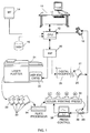
- Fig. 1 illustrates an integrated pre-press and printing system constructed and operative in accordance with the present invention.
- the system employs control strips which are compared to proof control strips in order to calibrate a press for a new original, and in order to control the printing of output sheets during a print run.
- the system comprises an operator interface workstation 10, such as a Prisma Workstation, commercially available from Scitex Corporation Ltd., Herzlia, Israel.
- the workstation 10 interfaces with a CPU 12, such as a Whisper, also commercially available from Scitex.
- the CPU 12 is arranged to interface with data storage apparatus such as a magnetic tape drive 14 and a disk drive 16 for receiving a digital file representing scanned or otherwise generated text and graphics information, which information will also be referred to here as "the main color image".
- a user creates a digital file on the workstation 10 which comprises a digital representation of a control strip.
- the user may retrieve a digital representation of a control strip from suitable electronic storage means such as disk 16.
- the digital file comprises a LW (linework) representation and/or a CT (continuous tone) representation.
- a digital representation of a control strip constructed in accordance with the method described herein may be a precursor of any of the following: a control strip 25 on a proof 27, control strips 32 on a plurality of color separation plates 30 and a control strip 40 on a printed output sheet 39.
- the CPU 12 outputs the digital files representing the main color image or images and the control strip to a screen generator 20, such as the screen generator described in U.S. Patent Nos. 4,350,996 and 4,456,924 to Rosenfeld, both assigned to the Applicant.
- the screen generator 20 preferably provides a full plate digital representation of the main image/s and of the control strips.
- the digital plate is characterized by screening parameters such as screen ruling, screen angle and dot shape.
- the screen ruling may be expressed in lines per inch and the screen angle in degrees.
- the dot shape may be of any suitable configuration, such as square, round, diamond or a computer optimized configuration.
- commercially available systems exist for allowing a user to define a desired dot shape. These systems include the Scitex User Dot (U-Dot) function operative in conjunction with the Scitex Prisma workstation or the Scitex Response 300 workstation, all commercially available from Scitex Corporation, Herzlia, Israel; and the Spot function used in conjunction with Adobe's Postscript format.
- the screen generator 20 interfaces with a digital proofer 26 which outputs proof 27 including the control strip 25.
- digital proofers include the Approval Digital Color Proofing System, by Eastman Kodak Co., Rochester, N.Y., U.S.A.; Digital Matchprint, by 3M; and the Iris, by Scitex Corporation.
- the screen generator 20 also interfaces with a laser beam controller 22 incorporated in a laser plotter 24, such as a Scitex Raystar plotter, commercially available from Scitex Corporation Ltd., Herzlia, Israel.
- the laser plotter 24 provides the color separation film and/or plates 30 including the control strips 32.
- the color separation plates 30 are typically processed in a plate processor 34, such as an Econo 65/85, commercially available from Ajax International Ballerup, Denmark.
- the processed plates 30 are mounted in a predetermined color sequence on a color printing press 36, such as a GTO series press, commercially available from Druckmaschinien AG, Heidelberg, Germany, for printing output sheets 39 including control strips 40.
- the operation of the printing press 36 is preferably automatically monitored by a press control device 38, such as a CPC, commercially available from Druckmaschinien AG, Heidelberg, West Germany and described in U.S. Patent No. 4,852,485 to Brunner, the disclosure of which is incorporated herein by reference.
- the press control device 38 utilizes the strip 40 to control variables such as the ink density and plate pressure of the printing press 36.
- the calibration of the printing press 36 for a new original is now described.
- the proof 27, including control strip 25, and the color separation plates 30 are produced as described hereinabove.
- the press 36 is set up and output sheet 39, including control strip 40, is produced.
- at least one element of control strip 40 is compared to the corresponding at least one element of control strip 25.
- the comparison may be performed visually, by a human operator, or, alternatively, automatically, using suitable apparatus such as a densitometer 18, which may comprise a Model 428 densitometer, commercially available from Xrite, Grandville, Michigan, U.S.A.
- the densitometer 18 can detect changes in the size and color density of a printed half tone dot compared to a proofed dot.
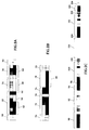
- Figs. 2A - 2C illustrate color control strips constructed and operative in accordance with preferred embodiments of the invention.
- the control strips of Figs. 2A-2C conform to international SWOP regulations. It is appreciated that the method and apparatus for generating control strips disclosed herein is not limited to generation of the specific control strips illustrated in Figs. 2A-2C or even to combinations of the features thereof. Figs. 2A-2C are intended only to be examples of possible control strip configurations.
- Fig. 2A illustrates a preferred embodiment of a control strip particularly suitable for monitoring color and registration qualities of a proof produced by a digital proofer.
- the control strip of Fig. 2A preferably includes the following elements: a registration target 50 comprising a plurality of relatively thin lines or curves for monitoring quality of registration; an array 52 of single color solids, two color overprints, three color overprints and four color overprints; cyan, magenta, yellow and black arrays 54, 56, 58 and 60, respectively, each comprising a plurality of patches differing in dot percentage, a gray balance array 62 and a white patch 64.
- Fig. 2B illustrates a preferred embodiment of a control strip particularly suitable for controlling plate exposure quality.
- the control strip of Fig. 2B preferably includes the following elements: a registration target 70; a gray scale array 72 comprising a sequence of steps having a fixed dot percentage interval between them such as 10%, for monitoring exposure linearity; a microline array 74 comprising a plurality of positive and negative microline patches, the microlines having varying widths within a suitable range such as 6 - 50 microns; an array 76 of diagonal, horizontal and vertical lines; a highlight array 78 comprising patches having relatively high dot percentages which typically vary from approximately 1% to 5%; and a shadow array 80 comprising patches having relatively low dot percentages which typically vary from approximately 95% to 99%.
- Fig. 2C illustrates a printing control strip, also termed a production control strip, suitable for printing on each output sheet 39 of Fig. 1 due to its particularly narrow configuration.
- the printing control strip of Fig. 2C preferably includes an array 90 of single color solids, two color overprints and three color overprints; a cyan array 92 comprising cyan patches of different dot percentages, including highlights and shadows, cyan microlines and a cyan slur target, a gray balance array 94; a solid black patch 96; a magenta array 100 comprising magenta patches of different dot percentages, including highlights and shadows, magenta microlines and a magenta slur target; a solid cyan patch 102; a yellow array 106 comprising yellow patches of different dot percentages, including highlights and shadows, yellow microlines and a yellow slur target; a solid magenta patch 108; a black array 112 comprising black patches of different dot percentages, black microlines and
- a user can design his own control strips.
- a user may delete any of the components, arrays and patches described above; may add suitable components, arrays or patches; may rearrange components within the control strip; may change the dimensions or orientation on the page of the control strip; or may change the parameters of any component, array or patch, such as but not limited to the dot shape thereof.
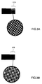
- Figs. 3A and 3B illustrate screening parameters of a 50% black patch 119 such as the 50% black patch of black array 112 in Fig. 2C.
- the patch 119 is formed of square dots oriented at a 30 o screen angle and having a screen ruling of 175 lines per inch.
- the patch 119 is formed of round dots oriented at a -7.5 o screen angle and having a screen ruling of 133 lines per inch. It is appreciated that the apparatus and method of the present invention, which provide a digital precursor of a control strip from which a control strip may be printed, allow a user to select any suitable value for any of the above screening parameters by inputting suitable options to screen generator 20 of Fig. 1. The result is a control strip with the user-selected screen parameters.
- a user may customize individual patches according to the particular printing application.
- Such customized patches may include a particularly configured registration target.
- Another type of customized patch is a custom color patch representing a particular color other than cyan, magenta, yellow and black, such as gold, silver, or Panton colors.
- the customized color patch is intended to monitor printing of a color employed in a particular printing application, generally in addition to the process colors.
- the custom colors are generally generated as additional plates and are overprinted in designated areas of the color image on the plate.
- the customized color may or may not be a combination of C, M, Y and K.
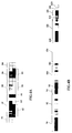
- Figs. 4A and 4B illustrate control strips including customized patches.
- the control strip of Fig. 4A is generally identical to the control strip of Fig. 2A except that, in Fig. 4A, white patch 64 of Fig. 2A is replaced by a customized color patch 120 representing a beige color important for a particular application.
- the control strip Fig. 4B is generally identical to the control strip of Fig. 2C except that customized beige color patch 120 is added.
- control strip as employed in the present specification and claims is not intended to be limited to conventional strip-like configurations but rather is intended to refer to a representation of a control color image employed mainly for controlling the reproduction of a main color image, the control color image having any suitable configuration.
- control strip is also not intended to exclude a representation of a control color image employed mainly for setting up a color printing device such as a press.
- Fig. 5 illustrates a full page color control strip or test form useful for monitoring the operation of a color writing device such as a press during press set up.
- control strip may be printed as either a positive or a negative.
Abstract
Description
- The present invention relates to electronic color pre-press and press systems and techniques generally.
- Control strips are particularly useful in monitoring the setting up of printing presses for new printing jobs by allowing careful comparison of the parameters of a printed product to the same parameters of a proof signed by a customer. Parameters which are compared include ink hues and densities, hues of secondary colors, dot gain/loss and halftone dot deformation as a result of slur or doubling. Control strips are also useful for maintaining printing parameters over a period of time to enable the printing of faithful copies of a proof of an original.
- Conventional control strips for offset or gravure color printing include off-the-shelf control strips which cannot be modified by a user. A wide variety of such strips are sold, under tradenames such as Chromalin by Dupont or Matchprint by 3M, to cater to different printing needs. Often printing workshops are required to stock large numbers of control strips to cover ordinary printing jobs.
- State of the art control strip patterns are described
in the following documents: Elyjiw, Zenon. "GATF Compact Color Test Strip", Research Project Report No. 6079, Graphics Arts Technical Foundation, Inc., Pittsburgh, PA: 1968. - GATF Quality Control Device Catalog, Graphic Arts Technical Foundation, Pittsburgh, PA: 1989.
- The application of control strips in the conventional printing and proof process is now briefly explained. A control strip is manually mounted with a color separation film on a plate. The plate is exposed and then developed. This stage is performed for each color separation needed to print copies of the original. A color proof is produced in a similar fashion.
- The plates are placed in a predetermined color sequence on a printing press, and the printing run is initiated. If the printing quality of output sheets is not satisfactory, as evidenced by comparison to the proof, then operation parameters of the printing press are changed accordingly to compensate for any deviations from the desired quality.
- This technology presents various problems which have been discussed in the literature, such as the problem of mutual registration of color separations discussed in U.S. Patent No. 4,469,025 to Loffler et al, automatic evaluation of the control strip discussed in U.S. Patent No. 4,448,533, and in-process control to deal with the problem of variation between copies discussed in U.S. Patent No. 4,852,485.
- State of the art technology has eliminated the film stage by enabling direct exposure of plates from digital information stored in a color electronic pre-press system. This technology is known as computer-to-plate (CTP) technology. A commercially available device for performing CTP is the Raystar Imagesetter, commercially available from Scitex Corporation, Herzlia, Israel.
- Similarly, a proofing process known as direct digital color proofing (DDCP) enabling direct exposure of proofs from digital information stored in a color electronic pre-press system has been developed and is known in the art. The Approval proofer, commercially available from Kodak, is an example of a DDCP device.
- Postscript is a format defined by Adobe Systems Inc., California, U.S.A., for defining page parameters such as types of letters and graphics parameters of images for output by a printer or film imagesetter. Initially, Postscript was used for black and white page printing. Electronically mountable control strips for black and white Postscript defined pages are known and are discussed in "Digital Control Wedge", UGRA Mitteilungen, Vol. 1, April 1990. The output of this type of process is a printed page or film provided by an imagesetter or printer.
- The present invention seeks to provide a control strip generated from a digital precursor as well as apparatus and methods for user generation of a control strip by creating a digital precursor of a control strip. The user generated control strips are preferably capable of being printed by a CTP device and a DDCP device.
- There is thus provided in accordance with a preferred embodiment of the present invention a control strip including an analog representation of a control color image useful in controlling the reproduction of a main color image, characterized in that the analog representation of the control color image was provided by the method of providing a digital representation of the control color image, and transforming the digital representation of the control color image into the analog representation of the control color image.
- Further in accordance with a preferred embodiment of the present invention, the step of transforming includes the steps of selecting at least one printing parameter, and printing the digital representation of the control color image in accordance with the at least one selected printing parameter.
- There is also provided in accordance with a further preferred embodiment of the present invention a method for providing a control strip, the control strip including an analog representation of a control color image useful in controlling the reproduction of a main color image, the method including the step of providing a digital representation of the control color image.
- Further in accordance with a preferred embodiment of the present invention, the step of transforming includes the steps of selecting at least one printing parameter, and printing the digital representation of the control color image in accordance with the at least one selected printing parameter.
- Still further in accordance with a preferred embodiment of the present invention, the at least one printing parameter includes at least one of the following group: screen angle, dot shape, screen ruling, dot gain, and gray balance.
- Additionally in accordance with a preferred embodiment of the present invention, the control color image includes at least one of the following group: solids of single colors, solids of two color overprints, solids of three color overprints, solids of four color overprints, colored tinted elements, colored microlines, colored slur targets, gray balance patches, registration targets, gray scale, highlights, and shadows.
- Further in accordance with a preferred embodiment of the present invention, the method also includes the step of transforming the digital representation of the control color image into an analog representation of the control color image.
- Still further in accordance with a preferred embodiment of the present invention, the step of transforming includes the steps of providing a digital representation of the main color image, and employing a color printing device to transform the digital representations of the main color image and of the control color image into an analog representation of a composite image, the composite image including the main color image and the control color image.
- Additionally in accordance with a preferred embodiment of the present invention, the step of transforming includes the step of determining the orientation of the control color image within the composite image.
- Further in accordance with a preferred embodiment of the present invention, the step of transforming includes the step of determining the location of the control color image within the composite image.
- Still further in accordance with a preferred embodiment of the present invention, the color printing device includes a printing press and/or a proofer.
- There is also provided in accordance with yet a further preferred embodiment of the present invention apparatus for providing a control strip, the control strip including an analog representation of a control color image useful in controlling the reproduction of a main color image, the apparatus including apparatus for providing a digital representation of the control color image, and apparatus for transforming the digital representation of the control color image into an analog representation of the control color image.
- There is further provided in accordance with yet a further preferred embodiment of the present invention an integrated pre-press and press system including apparatus for providing a digital representation of at least one main image and of at least one control strip corresponding to the at least one main image, proofing apparatus for receiving the digital representation and providing a proof including an analog representation of the at least one control strip, a press for receiving the digital representation and providing a printed output including an analog representation of the at least one main image and of the at least one control strip, and apparatus for controlling the operation of the press in accordance with the results of a comparison of the appearance of the printed output to the appearance of the proof.
- Further in accordance with a preferred embodiment of the present invention, the step of transforming includes the step of printing the control color image either as a positive or a negative.
- There is also provided in accordance with yet a further preferred embodiment of the present invention, digital storage apparatus including a digital representation of a control color image useful in controlling the reproduction of a main color image.
- Further in accordance with a preferred embodiment of the present invention, the digital storage apparatus also includes a digital representation of the main color image.
- The present invention will be understood and appreciated more fully from the following detailed description, taken in conjunction with the drawings in which:
- Fig. 1 is a generalized block diagram of an integrated pre-press and printing system useful for generating a control strip;
- Figs. 2A, 2B and 2C are color illustrations of control strips constructed and operative in accordance with preferred embodiments of the invention;
- Figs. 3A and 3B are color illustrations of portions of control strips having different screening parameters;
- Figs. 4A and 4B are color illustrations of control strips having custom patches; and
- Fig. 5 is a color illustration of a full page test form.
- Reference is now made to Fig. 1 which illustrates an integrated pre-press and printing system constructed and operative in accordance with the present invention. The system employs control strips which are compared to proof control strips in order to calibrate a press for a new original, and in order to control the printing of output sheets during a print run.
- The system comprises an
operator interface workstation 10, such as a Prisma Workstation, commercially available from Scitex Corporation Ltd., Herzlia, Israel. Theworkstation 10 interfaces with aCPU 12, such as a Whisper, also commercially available from Scitex. TheCPU 12 is arranged to interface with data storage apparatus such as amagnetic tape drive 14 and adisk drive 16 for receiving a digital file representing scanned or otherwise generated text and graphics information, which information will also be referred to here as "the main color image". - In accordance with a preferred embodiment of the present invention a user creates a digital file on the
workstation 10 which comprises a digital representation of a control strip. Alternatively, the user may retrieve a digital representation of a control strip from suitable electronic storage means such asdisk 16. According to a preferred embodiment of the invention, the digital file comprises a LW (linework) representation and/or a CT (continuous tone) representation. - It is appreciated that a digital representation of a control strip constructed in accordance with the method described herein may be a precursor of any of the following: a
control strip 25 on a proof 27, control strips 32 on a plurality ofcolor separation plates 30 and acontrol strip 40 on a printedoutput sheet 39. - The
CPU 12 outputs the digital files representing the main color image or images and the control strip to ascreen generator 20, such as the screen generator described in U.S. Patent Nos. 4,350,996 and 4,456,924 to Rosenfeld, both assigned to the Applicant. Thescreen generator 20 preferably provides a full plate digital representation of the main image/s and of the control strips. - The digital plate is characterized by screening parameters such as screen ruling, screen angle and dot shape. The screen ruling may be expressed in lines per inch and the screen angle in degrees. The dot shape may be of any suitable configuration, such as square, round, diamond or a computer optimized configuration. Alternatively, or in addition, commercially available systems exist for allowing a user to define a desired dot shape. These systems include the Scitex User Dot (U-Dot) function operative in conjunction with the Scitex Prisma workstation or the Scitex Response 300 workstation, all commercially available from Scitex Corporation, Herzlia, Israel; and the Spot function used in conjunction with Adobe's Postscript format.
- The
screen generator 20 interfaces with adigital proofer 26 which outputsproof 27 including thecontrol strip 25. Commercially available digital proofers include the Approval Digital Color Proofing System, by Eastman Kodak Co., Rochester, N.Y., U.S.A.; Digital Matchprint, by 3M; and the Iris, by Scitex Corporation. Thescreen generator 20 also interfaces with alaser beam controller 22 incorporated in alaser plotter 24, such as a Scitex Raystar plotter, commercially available from Scitex Corporation Ltd., Herzlia, Israel. - The
laser plotter 24 provides the color separation film and/orplates 30 including the control strips 32. Subsequently, thecolor separation plates 30 are typically processed in aplate processor 34, such as an Econo 65/85, commercially available from Ajax International Ballerup, Denmark. The processedplates 30 are mounted in a predetermined color sequence on acolor printing press 36, such as a GTO series press, commercially available from Druckmaschinien AG, Heidelberg, Germany, forprinting output sheets 39 including control strips 40. - The operation of the
printing press 36 is preferably automatically monitored by apress control device 38, such as a CPC, commercially available from Druckmaschinien AG, Heidelberg, West Germany and described in U.S. Patent No. 4,852,485 to Brunner, the disclosure of which is incorporated herein by reference. Thepress control device 38 utilizes thestrip 40 to control variables such as the ink density and plate pressure of theprinting press 36. - A detailed description of an integrated pre-press and press system is provided in Applicant's Israel Patent Application No. 97147, the disclosure of which is incorporated herein by reference.
- The calibration of the
printing press 36 for a new original is now described. First, theproof 27, includingcontrol strip 25, and thecolor separation plates 30 are produced as described hereinabove. Thepress 36 is set up andoutput sheet 39, includingcontrol strip 40, is produced. Subsequently, at least one element ofcontrol strip 40 is compared to the corresponding at least one element ofcontrol strip 25. - The comparison may be performed visually, by a human operator, or, alternatively, automatically, using suitable apparatus such as a
densitometer 18, which may comprise a Model 428 densitometer, commercially available from Xrite, Grandville, Michigan, U.S.A. Thedensitometer 18 can detect changes in the size and color density of a printed half tone dot compared to a proofed dot. - Reference is now made to Figs. 2A - 2C which illustrate color control strips constructed and operative in accordance with preferred embodiments of the invention. The control strips of Figs. 2A-2C conform to international SWOP regulations. It is appreciated that the method and apparatus for generating control strips disclosed herein is not limited to generation of the specific control strips illustrated in Figs. 2A-2C or even to combinations of the features thereof. Figs. 2A-2C are intended only to be examples of possible control strip configurations.
- Fig. 2A illustrates a preferred embodiment of a control strip particularly suitable for monitoring color and registration qualities of a proof produced by a digital proofer.
- The control strip of Fig. 2A preferably includes the following elements: a
registration target 50 comprising a plurality of relatively thin lines or curves for monitoring quality of registration; anarray 52 of single color solids, two color overprints, three color overprints and four color overprints; cyan, magenta, yellow andblack arrays gray balance array 62 and awhite patch 64. - Fig. 2B illustrates a preferred embodiment of a control strip particularly suitable for controlling plate exposure quality. The control strip of Fig. 2B preferably includes the following elements: a
registration target 70; agray scale array 72 comprising a sequence of steps having a fixed dot percentage interval between them such as 10%, for monitoring exposure linearity; amicroline array 74 comprising a plurality of positive and negative microline patches, the microlines having varying widths within a suitable range such as 6 - 50 microns; anarray 76 of diagonal, horizontal and vertical lines; ahighlight array 78 comprising patches having relatively high dot percentages which typically vary from approximately 1% to 5%; and ashadow array 80 comprising patches having relatively low dot percentages which typically vary from approximately 95% to 99%. - Fig. 2C illustrates a printing control strip, also termed a production control strip, suitable for printing on each
output sheet 39 of Fig. 1 due to its particularly narrow configuration. The printing control strip of Fig. 2C preferably includes anarray 90 of single color solids, two color overprints and three color overprints; acyan array 92 comprising cyan patches of different dot percentages, including highlights and shadows, cyan microlines and a cyan slur target, agray balance array 94; a solidblack patch 96; amagenta array 100 comprising magenta patches of different dot percentages, including highlights and shadows, magenta microlines and a magenta slur target; asolid cyan patch 102; ayellow array 106 comprising yellow patches of different dot percentages, including highlights and shadows, yellow microlines and a yellow slur target; asolid magenta patch 108; ablack array 112 comprising black patches of different dot percentages, black microlines and a black slur target; asolid cyan patch 114; agray balance array 116; and a solidwhite patch 118. - It is a particular feature of the present invention that the user can design his own control strips. A user may delete any of the components, arrays and patches described above; may add suitable components, arrays or patches; may rearrange components within the control strip; may change the dimensions or orientation on the page of the control strip; or may change the parameters of any component, array or patch, such as but not limited to the dot shape thereof.
- Reference is now made to Figs. 3A and 3B which illustrate screening parameters of a 50%
black patch 119 such as the 50% black patch ofblack array 112 in Fig. 2C. In Fig. 3A, thepatch 119 is formed of square dots oriented at a 30o screen angle and having a screen ruling of 175 lines per inch. In Fig. 3B, thepatch 119 is formed of round dots oriented at a -7.5o screen angle and having a screen ruling of 133 lines per inch. It is appreciated that the apparatus and method of the present invention, which provide a digital precursor of a control strip from which a control strip may be printed, allow a user to select any suitable value for any of the above screening parameters by inputting suitable options to screengenerator 20 of Fig. 1. The result is a control strip with the user-selected screen parameters. - It is a further feature of the present invention that a user may customize individual patches according to the particular printing application. Such customized patches may include a particularly configured registration target. Another type of customized patch is a custom color patch representing a particular color other than cyan, magenta, yellow and black, such as gold, silver, or Panton colors. The customized color patch is intended to monitor printing of a color employed in a particular printing application, generally in addition to the process colors. The custom colors are generally generated as additional plates and are overprinted in designated areas of the color image on the plate. The customized color may or may not be a combination of C, M, Y and K.
- Figs. 4A and 4B illustrate control strips including customized patches. The control strip of Fig. 4A is generally identical to the control strip of Fig. 2A except that, in Fig. 4A,
white patch 64 of Fig. 2A is replaced by a customizedcolor patch 120 representing a beige color important for a particular application. The control strip Fig. 4B, is generally identical to the control strip of Fig. 2C except that customizedbeige color patch 120 is added. - It is appreciated that the term "control strip" as employed in the present specification and claims is not intended to be limited to conventional strip-like configurations but rather is intended to refer to a representation of a control color image employed mainly for controlling the reproduction of a main color image, the control color image having any suitable configuration. The term "control strip" is also not intended to exclude a representation of a control color image employed mainly for setting up a color printing device such as a press. For example, Fig. 5 illustrates a full page color control strip or test form useful for monitoring the operation of a color writing device such as a press during press set up.
- A particular advantage of a digitally represented control strip is that the control strip may be printed as either a positive or a negative.
- It is appreciated that the method shown and described herein is particularly suited to providing control strips for use in direct digital proofing.
- It will be appreciated by persons skilled in the art that the present invention is not limited by what has been particularly shown and described hereinabove. Rather the scope of the present invention is defined only by the claims which follow:
Claims (20)
- A control strip comprising an analog representation of a control color image useful in controlling the reproduction of a main color image, characterized in that said analog representation of said control color image was provided by the following method:
providing a digital representation of said control color image; and
transforming said digital representation of said control color image into said analog representation of said control color image. - A control strip according to claim 1 and wherein said step of transforming comprises the steps of:
selecting at least one printing parameter; and
printing the digital representation of the control color image in accordance with the at least one selected printing parameter. - A control strip according to claim 2 and wherein said at least one printing parameter includes at least one of the following group:
screen angle;
dot shape;
screen ruling;
dot gain; and
gray balance. - A control strip according to any of the preceding claims and wherein said control color image comprises at least one of the following group:
solids of single colors;
solids of two color overprints;
solids of three color overprints;
solids of four color overprints;
half-tone patches;
colored microlines;
colored slur targets;
gray balance patches;
registration targets;
gray scale elements;
highlight dots; and
shadow dots. - A method for providing a control strip, said control strip comprising an analog representation of a control color image useful in controlling the reproduction of a main color image, the method comprising the step of:
providing a digital representation of said control color image. - A method according to claim 5 and also comprising the step of transforming said digital representation of said control color image into an analog representation of said control color image.
- A method according to claim 6 and wherein said step of transforming comprises the steps of:
selecting at least one printing parameter; and
printing the digital representation of the control color image in accordance with the at least one selected printing parameter. - A method according to claim 7 and wherein said at least one printing parameter includes at least one of the following group:
screen angle;
dot shape;
screen ruling;
dot gain; and
gray balance. - A method according to any of the preceding claims 5-8 and wherein said control color image comprises at least one of the following group:
solids of single colors;
solids of two color overprints;
solids of three color overprints;
solids of four color overprints;
colored tinted elements;
colored microlines;
colored slur targets;
gray balance patches;
registration targets;
gray scale;
highlights; and
shadows. - A method according to claim 6 wherein said step of transforming comprises the steps of:
providing a digital representation of the main color image; and
employing a color printing device to transform the digital representations of the main color image and of the control color image into an analog representation of a composite image, the composite image comprising the main color image and the control color image. - A method according to claim 10 wherein said step of transforming comprises the step of determining the orientation of the control color image within the composite image.
- A method according to claim 10 or 11 wherein said step of transforming comprises the step of determining the location of the control color image within the composite image.
- A method according to any of claims 10-12 wherein said color printing device comprises a printing press.
- A method according to any of claims 10-12 wherein said color printing device comprises a proofer.
- Apparatus for providing a control strip, said control strip comprising an analog representation of a control color image useful in controlling the reproduction of a main color image, the apparatus comprising:
means for providing a digital representation of said control color image; and
means for transforming said digital representation of said control color image into an analog representation of said control color image. - An integrated pre-press and press system comprising:
means for providing a digital representation of at least one main image and of at least one control strip corresponding to the at least one main image;
proofing means for receiving said digital representation and providing a proof comprising an analog representation of the at least one control strip;
a press for receiving said digital representation and providing a printed output comprising an analog representation of the at least one main image and of the at least one control strip; and
means for controlling the operation of the press in accordance with the results of a comparison of the appearance of the printed output to the appearance of the proof. - A method according to claim 6 and wherein said step of transforming comprises the step of printing the control color image as a positive.
- A method according to claim 6 and wherein said step of transforming comprises the step of printing the control color image as a negative.
- Digital storage apparatus comprising:
a digital representation of a control color image useful in controlling the reproduction of a main color image. - Digital storage apparatus according to claim 19 and also comprising a digital representation of the main color image.
Applications Claiming Priority (2)
| Application Number | Priority Date | Filing Date | Title |
|---|---|---|---|
| IL9845391A IL98453A (en) | 1991-06-11 | 1991-06-11 | Method and apparatus for creating a control strip |
| IL98453 | 1991-06-11 |
Publications (2)
| Publication Number | Publication Date |
|---|---|
| EP0518559A1 true EP0518559A1 (en) | 1992-12-16 |
| EP0518559B1 EP0518559B1 (en) | 1996-07-31 |
Family
ID=11062533
Family Applications (1)
| Application Number | Title | Priority Date | Filing Date |
|---|---|---|---|
| EP92305131A Revoked EP0518559B1 (en) | 1991-06-11 | 1992-06-04 | A method and apparatus for creating a control strip |
Country Status (6)
| Country | Link |
|---|---|
| US (1) | US5636330A (en) |
| EP (1) | EP0518559B1 (en) |
| AT (1) | ATE140896T1 (en) |
| DE (1) | DE69212539T2 (en) |
| HK (1) | HK1007537A1 (en) |
| IL (1) | IL98453A (en) |
Cited By (22)
| Publication number | Priority date | Publication date | Assignee | Title |
|---|---|---|---|---|
| GB2299783A (en) * | 1995-04-11 | 1996-10-16 | Scitex Corp Ltd | Printing press operator aide |
| EP0763427A2 (en) * | 1995-09-13 | 1997-03-19 | Heidelberger Druckmaschinen Aktiengesellschaft | Method for controlling the production of images on a printing plate carrier for a printing machine |
| DE19533811A1 (en) * | 1995-09-13 | 1997-03-20 | Heidelberger Druckmasch Ag | Controlling illustration of printed form carrier for printing press |
| GB2298985B (en) * | 1995-03-16 | 1999-08-04 | Highwater Designs Limited | Printing plate production |
| US6128090A (en) * | 1996-12-11 | 2000-10-03 | Agfa Gevaert N.V. | Visual control strip for imageable media |
| EP1080892A2 (en) * | 1999-09-06 | 2001-03-07 | Komori Corporation | Color management method and apparatus for printing press |
| US6219154B1 (en) | 1997-02-13 | 2001-04-17 | David J. Romano | Exposure control technique for imagesetting applications |
| EP1136266A1 (en) * | 2000-03-13 | 2001-09-26 | Dainippon Screen Mfg. Co., Ltd. | Ink control in printing press |
| EP1149703A2 (en) * | 2000-04-26 | 2001-10-31 | Dainippon Screen Mfg. Co., Ltd. | Method of and device for managing print colors, and image data processing device |
| US6535307B1 (en) | 1997-02-13 | 2003-03-18 | Agfa Corporation | Method and apparatus for display of imaging parameters |
| US6698355B2 (en) | 2002-04-24 | 2004-03-02 | Dainippon Screen Mfg. Co., Ltd. | Patch measurement device and printing apparatus incorporating the same |
| US6715417B2 (en) | 2000-10-13 | 2004-04-06 | Dainippon Screen Mfg. Co., Ltd. | Printing press equipped with color chart measuring apparatus |
| US6721061B1 (en) | 1997-02-13 | 2004-04-13 | Agfa Corporation | Method and apparatus for display of banding |
| DE102004009390A1 (en) * | 2004-02-24 | 2005-09-08 | Brüder Neumeister GmbH | Apparatus and method for determining the quality of imaging of printing plates |
| US7202973B2 (en) | 2001-07-04 | 2007-04-10 | Dainippon Screen Mfg. Co., Ltd. | Patch measurement device |
| US7206097B2 (en) | 2002-05-09 | 2007-04-17 | Dainippon Screen Mfg. Co., Ltd. | Patch measurement device and printing apparatus incorporating the same |
| DE102005041181A1 (en) * | 2005-08-31 | 2007-05-10 | Man Roland Druckmaschinen Ag | Pint control stripe producing method for e.g. controlling printing process, involves producing print control stripe by verifying for each color zone whether trapping for spectra color that is to be printed lies below threshold value |
| DE10041781B4 (en) * | 1999-08-25 | 2008-05-29 | Mitsubishi Paper Mills Limited | Digital prepress system |
| DE102007029211A1 (en) * | 2007-06-25 | 2009-01-08 | Heidelberger Druckmaschinen Ag | Improved print control strip for color measurement on substrates |
| EP2295256A1 (en) * | 2008-05-26 | 2011-03-16 | Wing King Tong Printing Limited | A neutral gray balance controlling method |
| EP2813364A1 (en) * | 2013-06-14 | 2014-12-17 | Fujifilm Corporation | Calibration data generation apparatus, method, and program |
| CN105313453A (en) * | 2014-08-04 | 2016-02-10 | 海德堡印刷机械股份公司 | Method for dynamic printing process calibration |
Families Citing this family (21)
| Publication number | Priority date | Publication date | Assignee | Title |
|---|---|---|---|---|
| JP3533007B2 (en) * | 1994-07-22 | 2004-05-31 | 株式会社リコー | Color sensor and image forming apparatus |
| US6318266B1 (en) * | 1995-04-11 | 2001-11-20 | Scitex Corporation Ltd. | Ink flow rate indicator |
| GB9609288D0 (en) * | 1996-05-03 | 1996-07-10 | Focoltone International Limite | Colour print standardisation |
| US6055065A (en) * | 1998-08-12 | 2000-04-25 | International Business Machines Corporation | Printer independent halftone image rendering |
| US6165654A (en) * | 1999-10-15 | 2000-12-26 | E. I. Du Pont De Nemours And Company | Analog and digital proofing image combinations |
| CA2439819A1 (en) * | 2001-03-02 | 2002-09-12 | The Ackley Martinez Company Dba Mgi Studio | Printing adjustment system and method |
| US6628426B2 (en) | 2001-05-22 | 2003-09-30 | Lexmark International, Inc. | Method of halftone screen linearization via continuous gradient patches |
| WO2003011598A1 (en) * | 2001-07-30 | 2003-02-13 | The Ackley Martinez Company Dba Mgi Studio | Color management processing system and method |
| US6725772B2 (en) | 2001-07-30 | 2004-04-27 | Ackley Martinez Company | System admixture compensation system and method |
| US7006250B2 (en) * | 2001-09-27 | 2006-02-28 | Lexmark International, Inc. | Method of setting laser power and developer bias in an electrophotographic machine based on an estimated intermediate belt reflectivity |
| US6917448B2 (en) * | 2002-05-22 | 2005-07-12 | Creo Il. Ltd. | Dot gain calibration method and apparatus |
| US6938550B2 (en) * | 2002-10-31 | 2005-09-06 | R. R. Donnelley & Sons, Co. | System and method for print screen tonal control and compensation |
| US20060152776A1 (en) * | 2004-06-23 | 2006-07-13 | Global Graphics Software, Inc. | Methods and systems for generating and using a control strip on proof prints |
| US7605959B2 (en) | 2005-01-05 | 2009-10-20 | The Ackley Martinez Company | System and method of color image transformation |
| US8274717B2 (en) * | 2006-08-01 | 2012-09-25 | Xerox Corporation | System and method for characterizing color separation misregistration |
| US8270049B2 (en) * | 2006-08-01 | 2012-09-18 | Xerox Corporation | System and method for high resolution characterization of spatial variance of color separation misregistration |
| US8228559B2 (en) * | 2007-05-21 | 2012-07-24 | Xerox Corporation | System and method for characterizing color separation misregistration utilizing a broadband multi-channel scanning module |
| US9179044B2 (en) * | 2007-07-13 | 2015-11-03 | Hewlett-Packard Development Company, L.P. | Color calibration |
| JP5547299B2 (en) * | 2009-12-17 | 2014-07-09 | 永経堂印刷有限公司 | Multi primary color printing method |
| ES2395182B1 (en) * | 2011-08-12 | 2013-11-28 | Comexi Group Industries, Sau | METHOD FOR CONTROLLING THE OPERATION OF A PRINTER MACHINE AND FLEXOGRAPHIC PRINTER MACHINE FOR IMPLEMENTATION. |
| JP2016116139A (en) * | 2014-12-16 | 2016-06-23 | キヤノン株式会社 | Image forming device, image forming method and program |
Citations (8)
| Publication number | Priority date | Publication date | Assignee | Title |
|---|---|---|---|---|
| US4299165A (en) * | 1979-02-22 | 1981-11-10 | C & H Printing | Color separation orientation gauge and method |
| EP0075270A1 (en) * | 1981-09-17 | 1983-03-30 | Kita Electronics Co., Ltd. | An apparatus for monitoring printed papers |
| EP0085750A1 (en) * | 1982-02-10 | 1983-08-17 | M.A.N.-ROLAND Druckmaschinen Aktiengesellschaft | Ink feed adjusting device in a rotary printing press |
| DE3316370A1 (en) * | 1982-05-19 | 1983-11-24 | Komori Printing Machinery Co., Ltd., Tokyo | METHOD AND SYSTEM FOR PROCESSING IMAGE SIGNALS |
| DE3325006A1 (en) * | 1982-10-26 | 1984-06-20 | VEB Kombinat Polygraph "Werner Lamberz" Leipzig, DDR 7050 Leipzig | DISPLAY DEVICE FOR COLOR CONTROL SYSTEMS |
| EP0255031A2 (en) * | 1986-07-22 | 1988-02-03 | Dainippon Screen Mfg. Co., Ltd. | Method of controlling dot gain on proof print |
| US4852485A (en) * | 1985-03-21 | 1989-08-01 | Felix Brunner | Method of operating an autotypical color offset printing machine |
| EP0394681A2 (en) * | 1989-04-24 | 1990-10-31 | Heidelberger Druckmaschinen Aktiengesellschaft | Method for regulating the ink supply in a printing machine with limitation of the ink film thickness and of the tonal value increase |
Family Cites Families (10)
| Publication number | Priority date | Publication date | Assignee | Title |
|---|---|---|---|---|
| DE2727227A1 (en) * | 1977-06-16 | 1978-12-21 | Heidelberger Druckmasch Ag | DEVICE FOR QUALITY ASSURANCE OF PRINT PRODUCTS |
| US4456924A (en) * | 1980-04-14 | 1984-06-26 | Scitex Corporation Ltd. | Screened image reproduction |
| US4350996A (en) * | 1980-04-14 | 1982-09-21 | Scitex Corporation Ltd. | Screened image reproduction |
| DE3219744A1 (en) * | 1982-05-26 | 1983-12-01 | Heidelberger Druckmaschinen Ag, 6900 Heidelberg | EQUIPMENT FOR STANDALIZED AND FIT FILM ASSEMBLY OF PRINT CONTROL STRIPS |
| DE3643721A1 (en) * | 1986-12-20 | 1988-06-30 | Heidelberger Druckmasch Ag | PRINT CONTROL STRIP |
| DE3643720C2 (en) * | 1986-12-20 | 1994-03-10 | Heidelberger Druckmasch Ag | Method for determining control variables for the inking unit of printing machines |
| CA2042033A1 (en) * | 1989-09-21 | 1991-03-22 | Thomas E. Lewis | Method and means for controlling overburn in spark-imaged lithography plates |
| US5339176A (en) * | 1990-02-05 | 1994-08-16 | Scitex Corporation Ltd. | Apparatus and method for color calibration |
| EP0451106B1 (en) * | 1990-04-06 | 1994-06-15 | GRETAG Aktiengesellschaft | Device for the analysis of printing test strips |
| IL97147A (en) * | 1991-02-04 | 1994-04-12 | Scitex Corp Ltd | Apparatus and techniques for computerized printing |
-
1991
- 1991-06-11 IL IL9845391A patent/IL98453A/en not_active IP Right Cessation
-
1992
- 1992-06-04 AT AT92305131T patent/ATE140896T1/en active
- 1992-06-04 DE DE69212539T patent/DE69212539T2/en not_active Expired - Fee Related
- 1992-06-04 EP EP92305131A patent/EP0518559B1/en not_active Revoked
-
1994
- 1994-11-08 US US08/335,664 patent/US5636330A/en not_active Expired - Fee Related
-
1998
- 1998-06-25 HK HK98106711A patent/HK1007537A1/en not_active IP Right Cessation
Patent Citations (8)
| Publication number | Priority date | Publication date | Assignee | Title |
|---|---|---|---|---|
| US4299165A (en) * | 1979-02-22 | 1981-11-10 | C & H Printing | Color separation orientation gauge and method |
| EP0075270A1 (en) * | 1981-09-17 | 1983-03-30 | Kita Electronics Co., Ltd. | An apparatus for monitoring printed papers |
| EP0085750A1 (en) * | 1982-02-10 | 1983-08-17 | M.A.N.-ROLAND Druckmaschinen Aktiengesellschaft | Ink feed adjusting device in a rotary printing press |
| DE3316370A1 (en) * | 1982-05-19 | 1983-11-24 | Komori Printing Machinery Co., Ltd., Tokyo | METHOD AND SYSTEM FOR PROCESSING IMAGE SIGNALS |
| DE3325006A1 (en) * | 1982-10-26 | 1984-06-20 | VEB Kombinat Polygraph "Werner Lamberz" Leipzig, DDR 7050 Leipzig | DISPLAY DEVICE FOR COLOR CONTROL SYSTEMS |
| US4852485A (en) * | 1985-03-21 | 1989-08-01 | Felix Brunner | Method of operating an autotypical color offset printing machine |
| EP0255031A2 (en) * | 1986-07-22 | 1988-02-03 | Dainippon Screen Mfg. Co., Ltd. | Method of controlling dot gain on proof print |
| EP0394681A2 (en) * | 1989-04-24 | 1990-10-31 | Heidelberger Druckmaschinen Aktiengesellschaft | Method for regulating the ink supply in a printing machine with limitation of the ink film thickness and of the tonal value increase |
Cited By (46)
| Publication number | Priority date | Publication date | Assignee | Title |
|---|---|---|---|---|
| GB2298985B (en) * | 1995-03-16 | 1999-08-04 | Highwater Designs Limited | Printing plate production |
| GB2299783B (en) * | 1995-04-11 | 1998-09-16 | Scitex Corp Ltd | Printing press operator aide |
| GB2299783A (en) * | 1995-04-11 | 1996-10-16 | Scitex Corp Ltd | Printing press operator aide |
| DE19533810A1 (en) * | 1995-09-13 | 1997-03-20 | Heidelberger Druckmasch Ag | Method for controlling the imaging of a printing form carrier for a printing press |
| EP0763427A3 (en) * | 1995-09-13 | 1997-07-16 | Heidelberger Druckmasch Ag | Method for controlling the production of images on a printing plate carrier for a printing machine |
| DE19533811A1 (en) * | 1995-09-13 | 1997-03-20 | Heidelberger Druckmasch Ag | Controlling illustration of printed form carrier for printing press |
| US6029576A (en) * | 1995-09-13 | 2000-02-29 | Heidelberger Druckmaschinen Ag | Method for controlling image formation on a printing form carrier for a printing press |
| EP0763427A2 (en) * | 1995-09-13 | 1997-03-19 | Heidelberger Druckmaschinen Aktiengesellschaft | Method for controlling the production of images on a printing plate carrier for a printing machine |
| DE19533810B4 (en) * | 1995-09-13 | 2006-04-20 | Heidelberger Druckmaschinen Ag | Method for controlling an imaging of a printing form support for a printing press |
| US6128090A (en) * | 1996-12-11 | 2000-10-03 | Agfa Gevaert N.V. | Visual control strip for imageable media |
| US6535307B1 (en) | 1997-02-13 | 2003-03-18 | Agfa Corporation | Method and apparatus for display of imaging parameters |
| US6219154B1 (en) | 1997-02-13 | 2001-04-17 | David J. Romano | Exposure control technique for imagesetting applications |
| US6721061B1 (en) | 1997-02-13 | 2004-04-13 | Agfa Corporation | Method and apparatus for display of banding |
| DE10041781B4 (en) * | 1999-08-25 | 2008-05-29 | Mitsubishi Paper Mills Limited | Digital prepress system |
| EP1080892A3 (en) * | 1999-09-06 | 2001-09-05 | Komori Corporation | Color management method and apparatus for printing press |
| EP1080892A2 (en) * | 1999-09-06 | 2001-03-07 | Komori Corporation | Color management method and apparatus for printing press |
| US7031022B1 (en) | 1999-09-06 | 2006-04-18 | Komori Corporation | Color management method and apparatus for printing press |
| EP1604822A2 (en) * | 2000-03-13 | 2005-12-14 | Dainippon Screen Mfg. Co., Ltd. | Ink control in printing press |
| US6539863B2 (en) | 2000-03-13 | 2003-04-01 | Dainippon Screen Mfg., Co., Ltd. | Ink control in printing press |
| EP1136266A1 (en) * | 2000-03-13 | 2001-09-26 | Dainippon Screen Mfg. Co., Ltd. | Ink control in printing press |
| US6684780B2 (en) | 2000-03-13 | 2004-02-03 | Dainippon Screen Mfg. Co., Ltd. | Ink control in printing press |
| EP1604822A3 (en) * | 2000-03-13 | 2005-12-28 | Dainippon Screen Mfg. Co., Ltd. | Ink control in printing press |
| EP1149703A3 (en) * | 2000-04-26 | 2002-09-04 | Dainippon Screen Mfg. Co., Ltd. | Method of and device for managing print colors, and image data processing device |
| US6999200B2 (en) | 2000-04-26 | 2006-02-14 | Dainippon Screen Mfg. Co., Ltd. | Method of and device for managing print colors, and image data processing device |
| EP1149703A2 (en) * | 2000-04-26 | 2001-10-31 | Dainippon Screen Mfg. Co., Ltd. | Method of and device for managing print colors, and image data processing device |
| US6860202B2 (en) | 2000-10-13 | 2005-03-01 | Dainippon Screen Mfg. Co., Ltd. | Printing press equipped with color chart measuring apparatus |
| US6715417B2 (en) | 2000-10-13 | 2004-04-06 | Dainippon Screen Mfg. Co., Ltd. | Printing press equipped with color chart measuring apparatus |
| US7131374B2 (en) | 2000-10-13 | 2006-11-07 | Dainippon Screen Mfg. Co., Ltd. | Printing press equipped with color chart measuring apparatus |
| US7202973B2 (en) | 2001-07-04 | 2007-04-10 | Dainippon Screen Mfg. Co., Ltd. | Patch measurement device |
| US6698355B2 (en) | 2002-04-24 | 2004-03-02 | Dainippon Screen Mfg. Co., Ltd. | Patch measurement device and printing apparatus incorporating the same |
| US7206097B2 (en) | 2002-05-09 | 2007-04-17 | Dainippon Screen Mfg. Co., Ltd. | Patch measurement device and printing apparatus incorporating the same |
| DE102004009390A1 (en) * | 2004-02-24 | 2005-09-08 | Brüder Neumeister GmbH | Apparatus and method for determining the quality of imaging of printing plates |
| DE102004009390B4 (en) * | 2004-02-24 | 2006-04-06 | Brüder Neumeister GmbH | Apparatus for determining the quality of imaging of printing plates |
| DE102005041181A1 (en) * | 2005-08-31 | 2007-05-10 | Man Roland Druckmaschinen Ag | Pint control stripe producing method for e.g. controlling printing process, involves producing print control stripe by verifying for each color zone whether trapping for spectra color that is to be printed lies below threshold value |
| DE102007029211A1 (en) * | 2007-06-25 | 2009-01-08 | Heidelberger Druckmaschinen Ag | Improved print control strip for color measurement on substrates |
| US8807033B2 (en) | 2007-06-25 | 2014-08-19 | Heidelberger Druckmachinen Ag | Print control strip for color measurement on printing material, measuring method and method of metering ink |
| EP2008818A3 (en) * | 2007-06-25 | 2012-04-04 | Heidelberger Druckmaschinen AG | Improved print control strips for measuring colour on printed material |
| EP2614958A1 (en) * | 2007-06-25 | 2013-07-17 | Heidelberger Druckmaschinen AG | Method for measuring colour fields |
| EP2295256A4 (en) * | 2008-05-26 | 2013-09-04 | Wing King Tong Printing Ltd | A neutral gray balance controlling method |
| EP2295256A1 (en) * | 2008-05-26 | 2011-03-16 | Wing King Tong Printing Limited | A neutral gray balance controlling method |
| EP2813364A1 (en) * | 2013-06-14 | 2014-12-17 | Fujifilm Corporation | Calibration data generation apparatus, method, and program |
| JP2015000516A (en) * | 2013-06-14 | 2015-01-05 | 富士フイルム株式会社 | Calibration data preparation device, method and program |
| CN105313453A (en) * | 2014-08-04 | 2016-02-10 | 海德堡印刷机械股份公司 | Method for dynamic printing process calibration |
| JP2016036139A (en) * | 2014-08-04 | 2016-03-17 | ハイデルベルガー ドルツクマシーネン アクチエンゲゼルシヤフトHeidelberger Druckmaschinen AG | Method of dynamically calibrating print process |
| US9626604B2 (en) | 2014-08-04 | 2017-04-18 | Heidelberger Druckmaschinen Ag | Method for dynamic printing process calibration |
| CN105313453B (en) * | 2014-08-04 | 2018-04-24 | 海德堡印刷机械股份公司 | Method for dynamic calibration printing process |
Also Published As
| Publication number | Publication date |
|---|---|
| IL98453A0 (en) | 1992-07-15 |
| EP0518559B1 (en) | 1996-07-31 |
| DE69212539T2 (en) | 1996-11-28 |
| DE69212539D1 (en) | 1996-09-05 |
| US5636330A (en) | 1997-06-03 |
| IL98453A (en) | 1996-06-18 |
| ATE140896T1 (en) | 1996-08-15 |
| HK1007537A1 (en) | 1999-04-16 |
Similar Documents
| Publication | Publication Date | Title |
|---|---|---|
| US5636330A (en) | Method and apparatus for creating a control strip | |
| EP1712361B1 (en) | Ink separation device for printing press ink feed control | |
| US6535307B1 (en) | Method and apparatus for display of imaging parameters | |
| US5598272A (en) | Visual calibrator for color halftone imaging | |
| US7400335B2 (en) | Method for printing a halftone digital image | |
| EP1385330B1 (en) | Print quality measuring method and print quality measuring apparatus | |
| US6970273B1 (en) | Method of tone reproduction with halftone dots, apparatus for outputting halftone plate, halftone plate, and printed material | |
| JP4535740B2 (en) | Color adjustment method in color proof | |
| US6441914B1 (en) | Prediction and prevention of offset printing press problems | |
| US5640254A (en) | Method for applying FM screening to a digital image | |
| US7196826B2 (en) | Image processing device and image processing system | |
| EP0847858B1 (en) | Visual control strip for imageable media | |
| US20040150844A1 (en) | Method for printing a color proof using a spatial filter | |
| EP0825022B1 (en) | Digital control strip for imageable media | |
| US5953498A (en) | Nonliner calibration of output devices | |
| EP1433605B1 (en) | Method and apparatus for controlling the Ink feeding rate | |
| US7057766B1 (en) | Apparatus for and method of outputting image | |
| US20050041038A1 (en) | Lookup table for adjusting dot-gain on bitmap files based on average number of dots | |
| EP1617647A1 (en) | Area coverage modulation image forming method | |
| US6893105B2 (en) | Method for printing an image from a halftone binary bitmap using multiple exposures | |
| US6863360B2 (en) | Method for adjusting dot-gain for a halftone binary bitmap | |
| Dharavath | Effect of Color Output Modification Approach (COMA) on the gray balance: A mismatch of device calibration, destination and source profiles, and halftone screening | |
| EP1481361B1 (en) | Method for rendering two output formats simultaneously | |
| JPH05278203A (en) | Integrated color separation system and method | |
| JP2005094456A (en) | Digital image output system and program |
Legal Events
| Date | Code | Title | Description |
|---|---|---|---|
| PUAI | Public reference made under article 153(3) epc to a published international application that has entered the european phase |
Free format text: ORIGINAL CODE: 0009012 |
|
| AK | Designated contracting states |
Kind code of ref document: A1 Designated state(s): AT BE CH DE DK ES FR GB GR IT LI LU MC NL PT SE |
|
| 17P | Request for examination filed |
Effective date: 19930511 |
|
| 17Q | First examination report despatched |
Effective date: 19941114 |
|
| GRAH | Despatch of communication of intention to grant a patent |
Free format text: ORIGINAL CODE: EPIDOS IGRA |
|
| GRAH | Despatch of communication of intention to grant a patent |
Free format text: ORIGINAL CODE: EPIDOS IGRA |
|
| GRAA | (expected) grant |
Free format text: ORIGINAL CODE: 0009210 |
|
| AK | Designated contracting states |
Kind code of ref document: B1 Designated state(s): AT BE CH DE DK ES FR GB GR IT LI LU MC NL PT SE |
|
| PG25 | Lapsed in a contracting state [announced via postgrant information from national office to epo] |
Ref country code: NL Free format text: LAPSE BECAUSE OF FAILURE TO SUBMIT A TRANSLATION OF THE DESCRIPTION OR TO PAY THE FEE WITHIN THE PRESCRIBED TIME-LIMIT Effective date: 19960731 Ref country code: LI Effective date: 19960731 Ref country code: IT Free format text: LAPSE BECAUSE OF FAILURE TO SUBMIT A TRANSLATION OF THE DESCRIPTION OR TO PAY THE FEE WITHIN THE PRE;WARNING: LAPSES OF ITALIAN PATENTS WITH EFFECTIVE DATE BEFORE 2007 MAY HAVE OCCURRED AT ANY TIME BEFORE 2007. THE CORRECT EFFECTIVE DATE MAY BE DIFFERENT FROM THE ONE RECORDED.SCRIBED TIME-LIMIT Effective date: 19960731 Ref country code: GR Free format text: LAPSE BECAUSE OF FAILURE TO SUBMIT A TRANSLATION OF THE DESCRIPTION OR TO PAY THE FEE WITHIN THE PRESCRIBED TIME-LIMIT Effective date: 19960731 Ref country code: FR Effective date: 19960731 Ref country code: ES Free format text: THE PATENT HAS BEEN ANNULLED BY A DECISION OF A NATIONAL AUTHORITY Effective date: 19960731 Ref country code: DK Effective date: 19960731 Ref country code: CH Effective date: 19960731 Ref country code: BE Effective date: 19960731 Ref country code: AT Effective date: 19960731 |
|
| REF | Corresponds to: |
Ref document number: 140896 Country of ref document: AT Date of ref document: 19960815 Kind code of ref document: T |
|
| REF | Corresponds to: |
Ref document number: 69212539 Country of ref document: DE Date of ref document: 19960905 |
|
| PG25 | Lapsed in a contracting state [announced via postgrant information from national office to epo] |
Ref country code: SE Effective date: 19961031 Ref country code: PT Effective date: 19961031 |
|
| EN | Fr: translation not filed | ||
| NLV1 | Nl: lapsed or annulled due to failure to fulfill the requirements of art. 29p and 29m of the patents act | ||
| REG | Reference to a national code |
Ref country code: CH Ref legal event code: PL |
|
| PLBI | Opposition filed |
Free format text: ORIGINAL CODE: 0009260 |
|
| PLBF | Reply of patent proprietor to notice(s) of opposition |
Free format text: ORIGINAL CODE: EPIDOS OBSO |
|
| 26 | Opposition filed |
Opponent name: MAN ROLAND DRUCKMASCHINEN AG Effective date: 19970426 |
|
| PG25 | Lapsed in a contracting state [announced via postgrant information from national office to epo] |
Ref country code: LU Free format text: LAPSE BECAUSE OF NON-PAYMENT OF DUE FEES Effective date: 19970630 |
|
| PLBF | Reply of patent proprietor to notice(s) of opposition |
Free format text: ORIGINAL CODE: EPIDOS OBSO |
|
| PG25 | Lapsed in a contracting state [announced via postgrant information from national office to epo] |
Ref country code: MC Effective date: 19971231 |
|
| PLBF | Reply of patent proprietor to notice(s) of opposition |
Free format text: ORIGINAL CODE: EPIDOS OBSO |
|
| PLBO | Opposition rejected |
Free format text: ORIGINAL CODE: EPIDOS REJO |
|
| APAC | Appeal dossier modified |
Free format text: ORIGINAL CODE: EPIDOS NOAPO |
|
| APAE | Appeal reference modified |
Free format text: ORIGINAL CODE: EPIDOS REFNO |
|
| APAC | Appeal dossier modified |
Free format text: ORIGINAL CODE: EPIDOS NOAPO |
|
| REG | Reference to a national code |
Ref country code: GB Ref legal event code: 732E |
|
| REG | Reference to a national code |
Ref country code: GB Ref legal event code: IF02 |
|
| PGFP | Annual fee paid to national office [announced via postgrant information from national office to epo] |
Ref country code: DE Payment date: 20020603 Year of fee payment: 11 |
|
| PGFP | Annual fee paid to national office [announced via postgrant information from national office to epo] |
Ref country code: GB Payment date: 20020605 Year of fee payment: 11 |
|
| RAP2 | Party data changed (patent owner data changed or rights of a patent transferred) |
Owner name: CREO IL. LTD. |
|
| RAP2 | Party data changed (patent owner data changed or rights of a patent transferred) |
Owner name: SCITEX CORPORATION LTD. |
|
| RAP2 | Party data changed (patent owner data changed or rights of a patent transferred) |
Owner name: CREO IL. LTD. |
|
| APAC | Appeal dossier modified |
Free format text: ORIGINAL CODE: EPIDOS NOAPO |
|
| RDAH | Patent revoked |
Free format text: ORIGINAL CODE: EPIDOS REVO |
|
| RDAG | Patent revoked |
Free format text: ORIGINAL CODE: 0009271 |
|
| STAA | Information on the status of an ep patent application or granted ep patent |
Free format text: STATUS: PATENT REVOKED |
|
| 27W | Patent revoked |
Effective date: 20021212 |
|
| GBPR | Gb: patent revoked under art. 102 of the ep convention designating the uk as contracting state |
Free format text: 20021212 |
|
| APAH | Appeal reference modified |
Free format text: ORIGINAL CODE: EPIDOSCREFNO |