EP0517899B1 - Systems and methods eradicating contaminants in fluids - Google Patents
Systems and methods eradicating contaminants in fluids Download PDFInfo
- Publication number
- EP0517899B1 EP0517899B1 EP92903506A EP92903506A EP0517899B1 EP 0517899 B1 EP0517899 B1 EP 0517899B1 EP 92903506 A EP92903506 A EP 92903506A EP 92903506 A EP92903506 A EP 92903506A EP 0517899 B1 EP0517899 B1 EP 0517899B1
- Authority
- EP
- European Patent Office
- Prior art keywords
- radiation
- fluid
- discrete
- sources
- source
- Prior art date
- Legal status (The legal status is an assumption and is not a legal conclusion. Google has not performed a legal analysis and makes no representation as to the accuracy of the status listed.)
- Expired - Lifetime
Links
Images


Classifications
-
- A—HUMAN NECESSITIES
- A61—MEDICAL OR VETERINARY SCIENCE; HYGIENE
- A61L—METHODS OR APPARATUS FOR STERILISING MATERIALS OR OBJECTS IN GENERAL; DISINFECTION, STERILISATION OR DEODORISATION OF AIR; CHEMICAL ASPECTS OF BANDAGES, DRESSINGS, ABSORBENT PADS OR SURGICAL ARTICLES; MATERIALS FOR BANDAGES, DRESSINGS, ABSORBENT PADS OR SURGICAL ARTICLES
- A61L2/00—Disinfection or sterilisation of materials or objects, in general; Accessories therefor
- A61L2/02—Disinfection or sterilisation of materials or objects, in general; Accessories therefor using physical processes
- A61L2/08—Radiation
-
- A—HUMAN NECESSITIES
- A61—MEDICAL OR VETERINARY SCIENCE; HYGIENE
- A61L—METHODS OR APPARATUS FOR STERILISING MATERIALS OR OBJECTS IN GENERAL; DISINFECTION, STERILISATION OR DEODORISATION OF AIR; CHEMICAL ASPECTS OF BANDAGES, DRESSINGS, ABSORBENT PADS OR SURGICAL ARTICLES; MATERIALS FOR BANDAGES, DRESSINGS, ABSORBENT PADS OR SURGICAL ARTICLES
- A61L2/00—Disinfection or sterilisation of materials or objects, in general; Accessories therefor
- A61L2/16—Disinfection or sterilisation of materials or objects, in general; Accessories therefor using chemical substances
- A61L2/18—Liquid substances
-
- A—HUMAN NECESSITIES
- A61—MEDICAL OR VETERINARY SCIENCE; HYGIENE
- A61M—DEVICES FOR INTRODUCING MEDIA INTO, OR ONTO, THE BODY; DEVICES FOR TRANSDUCING BODY MEDIA OR FOR TAKING MEDIA FROM THE BODY; DEVICES FOR PRODUCING OR ENDING SLEEP OR STUPOR
- A61M1/00—Suction or pumping devices for medical purposes; Devices for carrying-off, for treatment of, or for carrying-over, body-liquids; Drainage systems
- A61M1/36—Other treatment of blood in a by-pass of the natural circulatory system, e.g. temperature adaptation, irradiation ; Extra-corporeal blood circuits
- A61M1/3681—Other treatment of blood in a by-pass of the natural circulatory system, e.g. temperature adaptation, irradiation ; Extra-corporeal blood circuits by irradiation
- A61M1/3683—Other treatment of blood in a by-pass of the natural circulatory system, e.g. temperature adaptation, irradiation ; Extra-corporeal blood circuits by irradiation using photoactive agents
-
- B—PERFORMING OPERATIONS; TRANSPORTING
- B01—PHYSICAL OR CHEMICAL PROCESSES OR APPARATUS IN GENERAL
- B01J—CHEMICAL OR PHYSICAL PROCESSES, e.g. CATALYSIS OR COLLOID CHEMISTRY; THEIR RELEVANT APPARATUS
- B01J19/00—Chemical, physical or physico-chemical processes in general; Their relevant apparatus
- B01J19/08—Processes employing the direct application of electric or wave energy, or particle radiation; Apparatus therefor
- B01J19/12—Processes employing the direct application of electric or wave energy, or particle radiation; Apparatus therefor employing electromagnetic waves
- B01J19/122—Incoherent waves
-
- A—HUMAN NECESSITIES
- A61—MEDICAL OR VETERINARY SCIENCE; HYGIENE
- A61L—METHODS OR APPARATUS FOR STERILISING MATERIALS OR OBJECTS IN GENERAL; DISINFECTION, STERILISATION OR DEODORISATION OF AIR; CHEMICAL ASPECTS OF BANDAGES, DRESSINGS, ABSORBENT PADS OR SURGICAL ARTICLES; MATERIALS FOR BANDAGES, DRESSINGS, ABSORBENT PADS OR SURGICAL ARTICLES
- A61L2103/00—Materials or objects being the target of disinfection or sterilisation
- A61L2103/05—Living organisms or biological materials
Definitions
- the invention generally relates to an apparatus and method for the eradication of contaminants using photodynamic therapy, and particularly relates to the processing of whole blood and its components for storage and transfusion. In a more specific sense, the invention relates to the extracorporeal treatment of collected whole blood and its components with photoactive materials to eradicate viruses and other pathogenic contaminants.
- the clinically proven components of whole blood include red blood cells, used to treat chronic anemia; platelet-poor plasma, from which Clotting Factor VIII-rich cryoprecipitate can be obtained for the treatment of hemophilia; and concentrations of platelets, used to control thrombocytopenic bleeding.
- US-4915683 discloses the use of a single fluorescent light source for irradiating blood mixed with a photoactive agent.
- the present invention provides an apparatus as set out in claim 1, and a method as set out in claim 8.
- the pre-ambles of these claims are based on US-A-4915683.
- the inventors have discovered that apparatus and methods can be provided that accommodate relatively high processing flow rates and yet achieve an acceptably high rate of contaminant eradication through photodynamic therapy.
- the invention provides extracorporeal apparatus and methods that quickly and effectively eradicate infectious agents from fluids like blood by flowing the fluids with photoactive material added rapidly past a sequence of discrete radiation sources.
- One aspect of the invention provides an apparatus for treating a fluid carrying a contaminant to which a photoactive material has been bound.
- the system directs fluid through a predetermined flow path.
- the system establishes at least two discrete sources of radiation in the flow path at spaced apart locations along the direction of fluid flow.
- Each discrete source is a self-contained emitter of radiation that establishes its own zone of radiation.
- At least one of these discrete radiation sources comprises a photodiode.
- the system operates each discrete source of radiation at a selected wavelength within the prescribed range to activate the photoactive material bound to the contaminant.
- the apparatus operates to establish a flow of fluid through a treatment chamber in which the fluid is channelled in succession through at least two different flow paths.
- the apparatus establishes discrete sources of radiation along both flow paths.
- the apparatus places at least two of these discrete sources of radiation in the first path at spaced apart locations along the direction of fluid flow.
- the apparatus also places at least two additional discrete sources of radiation in the second path at spaced apart locations along the direction of fluid flow.
- the apparatus further includes a control element for operating each discrete source of radiation at a selected wavelength within a range that activates the photoactive material bound to the contaminant. Upon activation, the material eradicates the contaminant.
- the invention provides a surprisingly effective cumulative effect in terms of overall degree of contaminant eradication over a relatively short period of time.
- the apparatus also offers the flexibility to meet the needs of differing processing techniques.
- the control element operates the discrete sources of radiation at substantially the same wavelength.
- the control element operates at least two of the discrete sources of radiation at different wavelengths.
- At least two discrete sources of radiation are positioned along opposite sides of both the first and second flow paths.
- each discrete source of radiation comprises a photodiode.
- Each discrete source can thereby be controlled to emit a relatively narrow band of radiation having a relatively precise wavelength. The fluid passes rapidly through these well defined bands of radiation while being treated.
- photodiodes By using photodiodes as sources of radiation, relatively low voltages can be used.
- the low voltages reduce the amount of heat generated by the system, thereby preserving the viability of the fluid during treatment.
- Another aspect of the invention provides a method for treating a fluid carrying a contaminant to which a photoactive material has been bound.
- fluid is conveyed through a gap while being channelled through a predetermined flow path.
- the fluid is exposed to at least two discrete sources of radiation that are at spaced apart locations along the direction of fluid flow. At least one, and preferably all, of the discrete sources comprises a photodiode.
- fluid is conveyed through a gap while being channelled within the gap in succession through two different flow paths.
- the fluid is exposed to at least two discrete sources of radiation that are at spaced apart locations along the direction of fluid flow.
- the fluid is further exposed to at least two additional discrete sources of radiation that are also at spaced apart locations along the direction of fluid flow.
- Each discrete source of radiation is operated at a selected wavelength within the prescribed range to activate the photoactive material bound to the contaminant as the fluid flows in succession through the two paths.
- the invention is applicable for use in environments where sterility and biologically closed system integrity must be maintained during processing, therefore readily lend itself to blood processing applications.
- Fig. 1 shows an apparatus 10,(hereafter referred to as system 10) for treating a fluid carrying a contaminant that embodies the features of the invention.
- the system 10 includes a treatment device 12 that receives the fluid from a source container 14 and conveys the fluid after treatment to a collection container 16.
- the fluid to be treated can vary.
- the fluid comprises a component of whole human blood that is intended to be stored for transfusion. More specifically, the fluid consists of red blood cells suspended in plasma. Typically, a quantity of white blood cells is also present with the red blood cells.
- the fluid can also include an anticoagulant and, optionally, a storage medium for the blood component. Alternatively, the fluid can consist of platelets suspended in plasma.
- the contaminant comprises a pathogenic virus typically carried in the blood.
- the contaminant can consist of the hepatitis-B virus; the human immunodeficiency virus; the Herpes virus; or the influenza virus.
- the fluid in the source container 14 includes a photoactive material that has an affinity for the contaminant carried by the fluid.
- the photoactive material is added to the blood contained in the source container 14 after the blood is collected from a donor. The step of adding the photoactive material will be described in greater detail later.
- the photoactive material Due to its affinity for the contaminant, the photoactive material becomes bound to the contaminant within the source container 14.
- the photoactive material is of a type that becomes active by exposure to radiation within a prescribed wavelength range. When activated by radiation, the material eradicates the contaminant.
- the photoactive compound comprises a family of light-activated drugs derived from benzoporphyrin. These derivatives are commonly referred as BPD's. BPD's are commercially available from Quadra Logic Technologies, Inc., Vancouver B.C., Canada.
- BPD's like other types of hematoporphyrin materials, have an affinity for the cell walls of many viral organisms that are carried in blood. They therefore bind or attach themselves to the biological cell wall of these organisms. When exposed to radiation, BPD's undergo an energy transfer process with oxygen, forming a singlet oxygen. When the singlet oxygen oxidizes, it kills the biological cells to which it has attached. BPD's are described in greater detail in Judy et al U.S. Patent 4,878,891.
- the contaminant to which the BPD's is attached is exposed to the radiation in a predetermined manner as the fluid passes through the treatment device.
- the treatment device 12 includes body 18 that defines a treatment chamber 20.
- Two platens 22 and 24 on the body 18 form the treatment chamber 20.
- the first platen 22 is attached on the mid-portion of the body 18.
- the second platen 24 is carried on a door 26 that moves on the body 18 between an opened position (as Fig. 2 shows) and a closed position (as Figs. 1 and 3 show).
- the first and second platens 22 and 24 face each other in a spaced apart relationship, thereby forming the confines of the treatment chamber 20.
- the space between the two platens 22 and 24 forms a gap 28 of a predetermined size through which fluid traverses the chamber 20.
- the gap 28 is about 3.175 mm (0.125 inch) in width.
- the treatment device 12 further includes a plurality of radiation sources (generally designated by the numeral 30) positioned along the gap 28. Fluid traversing the chamber 20 is thereby exposed to the radiation sources 30.
- each platen 22 and 24 carries a number of radiation sources 30.
- each radiation source 30 is "discrete,” meaning that each source 30 is a self-contained emitter of radiation that establishes its own zone of radiation. Being discrete, each source 30 also is capable of operation to emit a radiation independent of the emission of radiation by the other sources 30.
- each radiation source 30 takes the form of a photodiode.
- Various types of photodiodes can be selected, depending upon the fluid to be treated and the characteristics of the photoactive material used. In the illustrated embodiment, where the treated fluid contains red blood cells, all the photodiodes use transparent substrate aluminum gallium arsenide material (TS AlGaAs). Photodiodes of this type are commercially available from Hewlett-Packard Co. (Product Designation "HLMP-8150 15 Candella").
- These photodiodes emit a band of radiation at a relatively narrow viewing angle of about 4 degrees.
- the prescribed band of radiation has a relatively precise wavelength displaying a red color having a peak wavelength of about 690 nm.
- Red blood cells are essentially transparent to radiation at this wavelength.
- the BPD's are not. The BPD's absorb radiation in this wavelength to become activated.
- the photodiode would be selected to have a wavelength displaying a blue color having peak wavelength of about 425 nm. Platelets are essentially transparent to radiation at this wavelength.
- each discrete photodiode radiation source has a minimum intensity of about 8.0 cd (at 20 mA), a maximum intensity of about 36.0 cd (at 20 mA), and a typical intensity of about 15.0 cd (at 20 mA).
- Each photodiode operates at a low maximum forward voltage of about 2.4 V.
- each bank or array 32 includes a plurality of discrete sources 30 arranged in alternating rows of four and five each (shown horizontally in Fig. 4). The alternating number in each row staggers the spacing of the sources 30 between adjacent rows. In the illustrated embodiment, each array 32 includes about 90 discrete radiation sources 30.
- each platen 22 and 24 is made of a clear glass or plastic material that is transparent to the radiation emitted by the sources.
- only one platen 22 or 24 would carry the radiation sources 30.
- the other platen would preferably carry a surface that reflects the radiation emitted by the sources 30 back into the gap 28.
- the surface of the other platen could be plated with gold or like highly reflective material to reflect the wavelengths of radiation described above.
- the treatment device includes a control element 34 for operating each discrete radiation source 30 (see Fig. 5).
- the radiation sources 30 are electrically interconnected in parallel banks 31, with each bank 31 containing five sources 30 in series connection.
- the fluid passes through the treatment chamber 20 from the source container 14 to the collection container 16 following a predetermined flow path 36 that embodies the features of the invention.
- the flow path 36 includes an inlet section 38 that conveys fluid from the source container 14 into the treatment chamber 20.
- the flow path 36 also includes an outlet section 40 that conveys fluid from the treatment chamber 20 to the collection container 16.
- the flow path 36 further includes an intermediate irradiation section 42 .
- One end of the irradiation section 42 communicates with the inlet section 38.
- Another end of the irradiation section 42 communicates with the outlet section 40.
- the inlet and outlet sections 38 and 40 are located outside the treatment chamber 20, while the irradiation section 42 is located within the treatment chamber 20, sandwiched between the two platens.
- the maximum size of the flow path 36 through the irradiation section 42 is defined by the gap 28 formed between the two platens 22 and 24.
- the irradiation section 42 is made of a material that is transparent to the radiation emitted by the sources. Fluid passing through the irradiation section 42 is thereby exposed to radiation.
- the irradiation section 42 defines at least two channels (generally designated by the letter C in Fig. 4).
- the channels direct fluid in different successive paths past the radiation sources.
- the irradiation section 42 includes eighteen (18) successive channels, which are numbered C1 to C18 accordingly. As Fig. 4 shows, the channels C1 to C18 are aligned in a prescribed fashion relative to the radiation sources 30.
- the channels C1 to C18 are aligned with respect to the radiation sources 30 so that, as the fluid passes through each channel, it is exposed to at least two discrete radiation sources 30.
- the fluid is exposed to at least eighteen discrete sources of radiation as it traverses each channel.
- the sources 30 associated with the first channel C1 are numbered S1 to S18 in Fig. 4.
- the channels C1 to C18 are further aligned so that, as the fluid passes through the next successive channel, it is exposed to different discrete sources of radiation.
- the eighteen radiation sources S1 to S18 in the first channel C1 are different than the radiation sources 30 associated with the next successive channel C2.
- the fluid passes through the irradiation section 42, it is not repeatedly exposed to the same source of radiation. Instead, it is exposed to numerous different sources of radiation, each one discrete unto itself. In the illustrated embodiment, the fluid is ultimately exposed at least once to about 360 discrete sources of radiation as it traverses the irradiation section 42.
- the source container 14, the collection container 16, and the irradiation section 42 each takes the form of a bag (respectively 44, 46, and 48) made of a flexible inert plastic material, like plasticized medical grade polyvinyl chloride.
- Each bag 44, 46, and 48 has heat sealed peripheral edges 50 to form a sealed interior area.
- the irradiation section bag 48 further includes a series of interior heat sealed regions 52 that divide the interior area into the eighteen interconnected flow passages.
- the flow passage comprise the channels C1 to C18, as just described.
- the irradiation section bag 48 is attached by pins 54 (see Figs. 2 and 4) to the first platen 22. With the door 26 closed, the channels C1 to C18 formed in the bag 48 direct fluid back and forth in a serpentine path past the radiation sources 30. As before described, the fluid is exposed to several discrete radiation sources 30 in each channel of this serpentine path. And, as also before described, in each successive channel, the fluid is further exposed to several more discrete radiation sources different than those encountered in the previous channel.
- the inlet section 38 of the flow path 36 includes a length of flexible inert plastic tubing 56 that joins the inlet end of the irradiation section bag 48.
- the tubing 56 includes a conventional inline filter 58 for removing the white blood cells from the fluid prior to entering the treatment chamber 20.
- the filtration medium used can include cotton wool, cellulose acetate, or another synthetic fiber like polyester.
- the tubing 56 terminates in a first connection device 60.
- the inlet section 38 further includes a length of flexible inert plastic tubing 62 that joins the source container 14.
- This tubing 62 includes a second connection device 64 that mates with the first connection device 60 to join the source container 14 to the inlet end of the irradiation section bag 48.
- connection devices 60 and 64 are preferable sterile connection devices like those shown in Granzow et al U.S. Patents 4,157,723 and 4,265,280, which are incorporated herein by reference.
- a peristaltic pump 66 conveys fluid through the fluid path 36 at a predetermined flow rate.
- the flow rate of the pump 66 will of course vary according to the volume of fluid that is to be treated and the time limitations imposed. In the context of illustrated embodiment, it is desirable to be able to treat 300 ml of blood components in about 30 minutes. Therefore, a preferred flow rate is about 10 ml/min.
- the outlet section 40 of the flow path 36 includes a length of flexible inert plastic tubing 68 that joins the outlet end of the irradiation section bag 48.
- the other end of the tubing 68 joins the collection container 16.
- the tubing could be normally separated into two lengths, like tubings 56 and 62, each having a (preferably sterile) connection device to join the collection container 16 to the outlet end of the irradiation section 42 prior to use.
- an auxiliary container 70 holds a solution containing the photoactive material.
- the auxiliary container 70 also includes a length of tubing 72 that carries with a third (preferably sterile) connection device 74.
- the source container 14 also includes another length of tubing 76 that carries a fourth (preferably sterile) connection device 78.
- the photoactive material can be conveyed from the auxiliary container 70 into the source container 14 for mixing with the fluid to be treated.
- the joined tubings 72 and 76 form a closed, internally sterile path for introducing the photoactive materially into the source container 14.
- the tubing 76 can be heat sealed closed upstream of the joined connection devices 74 and 78 (as Fig. 1 shows), and the auxiliary container 70 (with joined connection devices 74 and 78) removed.
- the formed flow path 36 comprises a closed, internally sterile path for conveying fluid from the source container 14, through the treatment chamber 20, and into the collection container 16.
- the fluid is exposed to a plurality of discrete sources 30 of radiation in the manner previously described.
- Each discrete radiation source 30 is operated by the control element 34 at a selected wavelength within the prescribed range to activate the photoactive material bound to the contaminant as the fluid flows in succession through the channels C1 to C18 in the irradiation section 42.
- the photoactive material is activated by exposure to the radiation to eradicate the contaminant.
- the fluid containing the eradicated contaminant is collected in the container 16 for storage and subsequent transfusion.
- control element 34 can be configured to operate two or more of the radiation sources at a different wavelength.
- control element 34 can be configured to operate two or more of the discrete sources 30 of radiation at substantially the same wavelength.
- each discrete source 30 can be varied, as can the intensity of radiation of each source 30.
- each platen 22 and 24 carries a number of radiation sources
- the discrete sources 30 of radiation are positioned along opposite sides of the gap 28 through which the fluid flows.
- the radiation sources 30 on the platens 22 and 24 can be arranged to be diametrically opposite to each other.
- Fig. 7 shows four pairs of diametrically opposite sources, designated S1 to S8.
- the zones of radiation designated Z1 to Z8, corresponding with their sources S1 to S8 directly overlap.
- the amount of radiation present in the converged zone CZ between each source is thereby intensified.
- Fig. 8 shows an alterative arrangement.
- the radiation sources S1 to S6 on the platens do not directly face one other. Instead, the sources S1 to S6 are staggered.
- the zones of radiation Z1 to Z6 emitted by the staggered sources do not directly overlap. Instead, they provide overlapping side regions ZS of intensified radiation between each discrete source S1 to S6.
- the following example demonstrates the effectiveness of the system 10 that embodies the features of the invention to process fluid undergoing photoactive therapy at relatively high flow rates.
- chamber was radiated from each side by a bank of 360 LED's at a wavelength of about 690 nm.
- the viral load was reduced during the treatment by two orders of magnitude (99%) from 10 6 units/ml to 10 4 units/ml.
Landscapes
- Health & Medical Sciences (AREA)
- General Health & Medical Sciences (AREA)
- Life Sciences & Earth Sciences (AREA)
- Animal Behavior & Ethology (AREA)
- Public Health (AREA)
- Veterinary Medicine (AREA)
- Vascular Medicine (AREA)
- Heart & Thoracic Surgery (AREA)
- Epidemiology (AREA)
- Chemical & Material Sciences (AREA)
- Anesthesiology (AREA)
- Engineering & Computer Science (AREA)
- Hematology (AREA)
- Biomedical Technology (AREA)
- Cardiology (AREA)
- Chemical Kinetics & Catalysis (AREA)
- Physics & Mathematics (AREA)
- Electromagnetism (AREA)
- Organic Chemistry (AREA)
- Toxicology (AREA)
- General Chemical & Material Sciences (AREA)
- Apparatus For Disinfection Or Sterilisation (AREA)
- External Artificial Organs (AREA)
- Micro-Organisms Or Cultivation Processes Thereof (AREA)
- Electrostatic Charge, Transfer And Separation In Electrography (AREA)
- Infusion, Injection, And Reservoir Apparatuses (AREA)
Description
- The invention generally relates to an apparatus and method for the eradication of contaminants using photodynamic therapy, and particularly relates to the processing of whole blood and its components for storage and transfusion. In a more specific sense, the invention relates to the extracorporeal treatment of collected whole blood and its components with photoactive materials to eradicate viruses and other pathogenic contaminants.
- With the coming of blood component therapy, most whole blood collected today is separated into its clinically proven components for storage and administration. The clinically proven components of whole blood include red blood cells, used to treat chronic anemia; platelet-poor plasma, from which Clotting Factor VIII-rich cryoprecipitate can be obtained for the treatment of hemophilia; and concentrations of platelets, used to control thrombocytopenic bleeding.
- It is well known that blood can carry infectious agents like hepatitis-B virus; the human immunodeficiency (AIDS) virus; the Herpes virus; and the influenza virus. To avoid the transmission of these infectious agents during blood transfusions, donors of blood are routinely screened and also undergo serologic testing to detect the presence of these agents. Still, it is difficult to always assure that these infectious agents are detected.
- The use of photodynamic therapy has been suggested as a way to eradicate infectious agents from collected blood and its components prior to storage and transfusion. See Matthews et al, "Photodynamic Therapy of Viral Contaminants With Potential for Blood Bank Applications," Transfusion, 28(1), pp. 81-83 (1988). Various extracorporeal systems have been proposed that use photodynamic therapy to treat blood prior to storage and transfusion. See, for example, Edelson U.S. Patents 4,613,322 and 4,684,521; Troutner et al U.S. Patent 4,708,715; Wiesehahn et al U.S. Patent 4,727,027; Sieber U.S. Patents 4,775,625 and 4,915,683; and Judy et al U.S. Patent 4,878,891.
- US-4915683 discloses the use of a single fluorescent light source for irradiating blood mixed with a photoactive agent.
- To date, there has been a general lack of success in economically adapting the benefits of photodynamic therapy to the demands of the blood banking industry. The extracorporeal systems proposed to date have not been able to provide acceptable levels of eradication at the relatively high flow rates required to economically process therapeutic units of blood components.
- For this and other reasons, the promise of photodynamic therapy in treating the nation's banked blood supply has gone largely unfulfilled.
- The present invention provides an apparatus as set out in claim 1, and a method as set out in
claim 8. The pre-ambles of these claims are based on US-A-4915683. - The inventors have discovered that apparatus and methods can be provided that accommodate relatively high processing flow rates and yet achieve an acceptably high rate of contaminant eradication through photodynamic therapy. The invention provides extracorporeal apparatus and methods that quickly and effectively eradicate infectious agents from fluids like blood by flowing the fluids with photoactive material added rapidly past a sequence of discrete radiation sources.
- One aspect of the invention provides an apparatus for treating a fluid carrying a contaminant to which a photoactive material has been bound. The system directs fluid through a predetermined flow path. The system establishes at least two discrete sources of radiation in the flow path at spaced apart locations along the direction of fluid flow. Each discrete source is a self-contained emitter of radiation that establishes its own zone of radiation. At least one of these discrete radiation sources comprises a photodiode. The system, operates each discrete source of radiation at a selected wavelength within the prescribed range to activate the photoactive material bound to the contaminant.
- According to a preferred aspect of the invention, the apparatus operates to establish a flow of fluid through a treatment chamber in which the fluid is channelled in succession through at least two different flow paths.
- According to this aspect, the apparatus establishes discrete sources of radiation along both flow paths. The apparatus places at least two of these discrete sources of radiation in the first path at spaced apart locations along the direction of fluid flow. The apparatus also places at least two additional discrete sources of radiation in the second path at spaced apart locations along the direction of fluid flow.
- The apparatus further includes a control element for operating each discrete source of radiation at a selected wavelength within a range that activates the photoactive material bound to the contaminant. Upon activation, the material eradicates the contaminant.
- By channeling the fluid through several discrete zones of radiation at a relatively high flow rate, the invention provides a surprisingly effective cumulative effect in terms of overall degree of contaminant eradication over a relatively short period of time.
- By using discrete sources of radiation, the apparatus also offers the flexibility to meet the needs of differing processing techniques. For example, in one arrangement, the control element operates the discrete sources of radiation at substantially the same wavelength. In another arrangement, the control element operates at least two of the discrete sources of radiation at different wavelengths.
- In a preferred embodiment, at least two discrete sources of radiation are positioned along opposite sides of both the first and second flow paths. In this preferred arrangement, there are at least three discrete sources of light positioned along each flow path. Two of the discrete sources are positioned at spaced apart locations along one side of the flow path in the direction of fluid flow, while the other discrete source is positioned on an opposite side of the flow path.
- In a preferred embodiment, each discrete source of radiation comprises a photodiode. Each discrete source can thereby be controlled to emit a relatively narrow band of radiation having a relatively precise wavelength. The fluid passes rapidly through these well defined bands of radiation while being treated.
- By using photodiodes as sources of radiation, relatively low voltages can be used. The low voltages reduce the amount of heat generated by the system, thereby preserving the viability of the fluid during treatment.
- Another aspect of the invention provides a method for treating a fluid carrying a contaminant to which a photoactive material has been bound. According to this aspect of the invention, fluid is conveyed through a gap while being channelled through a predetermined flow path. As it transits the flow path, the fluid is exposed to at least two discrete sources of radiation that are at spaced apart locations along the direction of fluid flow. At least one, and preferably all, of the discrete sources comprises a photodiode.
- In a preferred arrangement, fluid is conveyed through a gap while being channelled within the gap in succession through two different flow paths. As it transits the first flow path, the fluid is exposed to at least two discrete sources of radiation that are at spaced apart locations along the direction of fluid flow. As it next transits the second flow path, the fluid is further exposed to at least two additional discrete sources of radiation that are also at spaced apart locations along the direction of fluid flow. Each discrete source of radiation is operated at a selected wavelength within the prescribed range to activate the photoactive material bound to the contaminant as the fluid flows in succession through the two paths.
- The invention is applicable for use in environments where sterility and biologically closed system integrity must be maintained during processing, therefore readily lend itself to blood processing applications.
- Other features and advantages of the invention will be pointed out in, or will be apparent from, the drawings, specification and claims that follow.
-
- Fig. 1 is a perspective view, with portions broken away, of an apparatus for treating a fluid carrying a contaminant with the treatment chamber closed as it is in use;
- Fig. 2 is a perspective view of the apparatus shown in Fig. 1, with the treatment chamber opened to receive the irradiation section of the associated fluid flow path prior to use;
- Fig. 3 is a section view of the closed treatment chamber taken generally along line 3-3 in Fig. 1;
- Fig. 4 is a view of the irradiation section of the fluid path in place within the treatment chamber, taken generally along line 4-4 in Fig. 3;
- Fig. 5 is a schematic view of the control element that operates the discrete sources of radiation located within the treatment chamber;
- Fig. 6 is a perspective view of the component parts of the fluid flow path associated with the system shown in Fig. 1, with the component parts disassembled prior to use;
- Fig. 7 is an enlarged view of a portion of the treatment chamber showing one arrangement of the discrete radiation sources along the irradiation section of the flow path; and
- Fig. 8 is an enlarged view of a portion of the treatment chamber showing another arrangement of the discrete radiation sources along the irradiation section of the flow path.
-
- The invention is not limited to the details of the construction and the arrangements of parts set forth in the following description or shown in the drawings. The invention can be practiced in other embodiments and in various other ways. The terminology and phrases are used for description and should not be regarded as limiting.
- Fig. 1 shows an
apparatus 10,(hereafter referred to as system 10) for treating a fluid carrying a contaminant that embodies the features of the invention. Thesystem 10 includes atreatment device 12 that receives the fluid from asource container 14 and conveys the fluid after treatment to acollection container 16. - The fluid to be treated can vary. In the illustrated embodiment, the fluid comprises a component of whole human blood that is intended to be stored for transfusion. More specifically, the fluid consists of red blood cells suspended in plasma. Typically, a quantity of white blood cells is also present with the red blood cells. The fluid can also include an anticoagulant and, optionally, a storage medium for the blood component. Alternatively, the fluid can consist of platelets suspended in plasma.
- In the illustrated embodiment, the contaminant comprises a pathogenic virus typically carried in the blood. For example, the contaminant can consist of the hepatitis-B virus; the human immunodeficiency virus; the Herpes virus; or the influenza virus.
- The fluid in the
source container 14 includes a photoactive material that has an affinity for the contaminant carried by the fluid. The photoactive material is added to the blood contained in thesource container 14 after the blood is collected from a donor. The step of adding the photoactive material will be described in greater detail later. - Due to its affinity for the contaminant, the photoactive material becomes bound to the contaminant within the
source container 14. The photoactive material is of a type that becomes active by exposure to radiation within a prescribed wavelength range. When activated by radiation, the material eradicates the contaminant. - Various types of photoactive materials can be used. In the illustrated embodiment, the photoactive compound comprises a family of light-activated drugs derived from benzoporphyrin. These derivatives are commonly referred as BPD's. BPD's are commercially available from Quadra Logic Technologies, Inc., Vancouver B.C., Canada.
- BPD's, like other types of hematoporphyrin materials, have an affinity for the cell walls of many viral organisms that are carried in blood. They therefore bind or attach themselves to the biological cell wall of these organisms. When exposed to radiation, BPD's undergo an energy transfer process with oxygen, forming a singlet oxygen. When the singlet oxygen oxidizes, it kills the biological cells to which it has attached. BPD's are described in greater detail in Judy et al U.S. Patent 4,878,891.
- According to the invention, the contaminant to which the BPD's is attached is exposed to the radiation in a predetermined manner as the fluid passes through the treatment device.
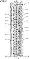
- As Figs. 2 and 3 best show, the
treatment device 12 includesbody 18 that defines atreatment chamber 20. Twoplatens body 18 form thetreatment chamber 20. Thefirst platen 22 is attached on the mid-portion of thebody 18. Thesecond platen 24 is carried on adoor 26 that moves on thebody 18 between an opened position (as Fig. 2 shows) and a closed position (as Figs. 1 and 3 show). - As best shown in Fig. 3, when the
door 26 is in its closed position, the first andsecond platens treatment chamber 20. The space between the twoplatens gap 28 of a predetermined size through which fluid traverses thechamber 20. In the illustrated embodiment, thegap 28 is about 3.175 mm (0.125 inch) in width. - The
treatment device 12 further includes a plurality of radiation sources (generally designated by the numeral 30) positioned along thegap 28. Fluid traversing thechamber 20 is thereby exposed to the radiation sources 30. In the illustrated embodiment, eachplaten - According to the invention, each
radiation source 30 is "discrete," meaning that eachsource 30 is a self-contained emitter of radiation that establishes its own zone of radiation. Being discrete, eachsource 30 also is capable of operation to emit a radiation independent of the emission of radiation by theother sources 30. - In the illustrated and preferred embodiment, each
radiation source 30 takes the form of a photodiode. Various types of photodiodes can be selected, depending upon the fluid to be treated and the characteristics of the photoactive material used. In the illustrated embodiment, where the treated fluid contains red blood cells, all the photodiodes use transparent substrate aluminum gallium arsenide material (TS AlGaAs). Photodiodes of this type are commercially available from Hewlett-Packard Co. (Product Designation "HLMP-8150 15 Candella"). - These photodiodes emit a band of radiation at a relatively narrow viewing angle of about 4 degrees. The prescribed band of radiation has a relatively precise wavelength displaying a red color having a peak wavelength of about 690 nm. Red blood cells are essentially transparent to radiation at this wavelength. The BPD's, however, are not. The BPD's absorb radiation in this wavelength to become activated.
- If the fluid to be treated contains platelets, the photodiode would be selected to have a wavelength displaying a blue color having peak wavelength of about 425 nm. Platelets are essentially transparent to radiation at this wavelength.
- In the illustrated embodiment, each discrete photodiode radiation source has a minimum intensity of about 8.0 cd (at 20 mA), a maximum intensity of about 36.0 cd (at 20 mA), and a typical intensity of about 15.0 cd (at 20 mA). Each photodiode operates at a low maximum forward voltage of about 2.4 V.
- In the illustrated embodiment (as Fig. 4 best shows), the
discrete radiation sources 30 are arranged in banks orarrays 32 on eachplaten array 32 includes a plurality ofdiscrete sources 30 arranged in alternating rows of four and five each (shown horizontally in Fig. 4). The alternating number in each row staggers the spacing of thesources 30 between adjacent rows. In the illustrated embodiment, eacharray 32 includes about 90 discrete radiation sources 30. - In the illustrated arrangement (as Fig. 2 shows), four
arrays 32 are carried on thebody 18 behind the first platen 22 (comprising about 360 discrete sources of radiation). Fouradditional arrays 32 are carried on thedoor 26 behind thesecond platen 24. Eachplaten - In an alternative arrangement (not shown), only one
platen sources 30 back into thegap 28. For example, the surface of the other platen could be plated with gold or like highly reflective material to reflect the wavelengths of radiation described above. - The treatment device includes a
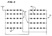
control element 34 for operating each discrete radiation source 30 (see Fig. 5). As Fig. 5 shows, theradiation sources 30 are electrically interconnected inparallel banks 31, with eachbank 31 containing fivesources 30 in series connection. - As Fig. 1 shows, the fluid passes through the
treatment chamber 20 from thesource container 14 to thecollection container 16 following apredetermined flow path 36 that embodies the features of the invention. Theflow path 36 includes aninlet section 38 that conveys fluid from thesource container 14 into thetreatment chamber 20. Theflow path 36 also includes anoutlet section 40 that conveys fluid from thetreatment chamber 20 to thecollection container 16. - The
flow path 36 further includes anintermediate irradiation section 42 . One end of theirradiation section 42 communicates with theinlet section 38. Another end of theirradiation section 42 communicates with theoutlet section 40. - In use (as Fig. 1 shows), the inlet and
outlet sections treatment chamber 20, while theirradiation section 42 is located within thetreatment chamber 20, sandwiched between the two platens. The maximum size of theflow path 36 through theirradiation section 42 is defined by thegap 28 formed between the twoplatens - The
irradiation section 42 is made of a material that is transparent to the radiation emitted by the sources. Fluid passing through theirradiation section 42 is thereby exposed to radiation. - The
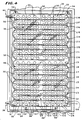
irradiation section 42 defines at least two channels (generally designated by the letter C in Fig. 4). The channels direct fluid in different successive paths past the radiation sources. In the illustrated embodiment, theirradiation section 42 includes eighteen (18) successive channels, which are numbered C1 to C18 accordingly. As Fig. 4 shows, the channels C1 to C18 are aligned in a prescribed fashion relative to the radiation sources 30. - More particularly, the channels C1 to C18 are aligned with respect to the
radiation sources 30 so that, as the fluid passes through each channel, it is exposed to at least two discrete radiation sources 30. In the illustrated embodiment, the fluid is exposed to at least eighteen discrete sources of radiation as it traverses each channel. For illustration purposes, thesources 30 associated with the first channel C1 are numbered S1 to S18 in Fig. 4. - The channels C1 to C18 are further aligned so that, as the fluid passes through the next successive channel, it is exposed to different discrete sources of radiation. For example, the eighteen radiation sources S1 to S18 in the first channel C1 are different than the
radiation sources 30 associated with the next successive channel C2. In addition, there may be some overlap betweensources 30 between adjacent channels. - Therefore, as the fluid passes through the
irradiation section 42, it is not repeatedly exposed to the same source of radiation. Instead, it is exposed to numerous different sources of radiation, each one discrete unto itself. In the illustrated embodiment, the fluid is ultimately exposed at least once to about 360 discrete sources of radiation as it traverses theirradiation section 42. - In the illustrated embodiment, the
source container 14, thecollection container 16, and theirradiation section 42 each takes the form of a bag (respectively 44, 46, and 48) made of a flexible inert plastic material, like plasticized medical grade polyvinyl chloride. Eachbag peripheral edges 50 to form a sealed interior area. - The
irradiation section bag 48 further includes a series of interior heat sealedregions 52 that divide the interior area into the eighteen interconnected flow passages. The flow passage comprise the channels C1 to C18, as just described. - The
irradiation section bag 48 is attached by pins 54 (see Figs. 2 and 4) to thefirst platen 22. With thedoor 26 closed, the channels C1 to C18 formed in thebag 48 direct fluid back and forth in a serpentine path past the radiation sources 30. As before described, the fluid is exposed to severaldiscrete radiation sources 30 in each channel of this serpentine path. And, as also before described, in each successive channel, the fluid is further exposed to several more discrete radiation sources different than those encountered in the previous channel. - In the illustrated embodiment (see Fig. 6), the
inlet section 38 of theflow path 36 includes a length of flexible inertplastic tubing 56 that joins the inlet end of theirradiation section bag 48. Thetubing 56 includes a conventionalinline filter 58 for removing the white blood cells from the fluid prior to entering thetreatment chamber 20. The filtration medium used (not shown) can include cotton wool, cellulose acetate, or another synthetic fiber like polyester. - The
tubing 56 terminates in afirst connection device 60. - The
inlet section 38 further includes a length of flexible inertplastic tubing 62 that joins thesource container 14. Thistubing 62 includes asecond connection device 64 that mates with thefirst connection device 60 to join thesource container 14 to the inlet end of theirradiation section bag 48. - While various known connection devices may be used, in the illustrated embodiment, the
devices - In use, a peristaltic pump 66 (see Fig. 1) conveys fluid through the
fluid path 36 at a predetermined flow rate. The flow rate of thepump 66 will of course vary according to the volume of fluid that is to be treated and the time limitations imposed. In the context of illustrated embodiment, it is desirable to be able to treat 300 ml of blood components in about 30 minutes. Therefore, a preferred flow rate is about 10 ml/min. - The
outlet section 40 of theflow path 36 includes a length of flexible inertplastic tubing 68 that joins the outlet end of theirradiation section bag 48. The other end of thetubing 68 joins thecollection container 16. In an alternative arrangement (not shown), the tubing could be normally separated into two lengths, like tubings 56 and 62, each having a (preferably sterile) connection device to join thecollection container 16 to the outlet end of theirradiation section 42 prior to use. - In the illustrated embodiment (see Fig. 6), an
auxiliary container 70 holds a solution containing the photoactive material. Theauxiliary container 70 also includes a length oftubing 72 that carries with a third (preferably sterile)connection device 74. In this arrangement, thesource container 14 also includes another length oftubing 76 that carries a fourth (preferably sterile)connection device 78. By joining the third andfourth connection devices auxiliary container 70 into thesource container 14 for mixing with the fluid to be treated. The joinedtubings source container 14. Once the photoactive material has been transferred, thetubing 76 can be heat sealed closed upstream of the joinedconnection devices 74 and 78 (as Fig. 1 shows), and the auxiliary container 70 (with joinedconnection devices 74 and 78) removed. - By using the
sterile connection devices flow path 36 comprises a closed, internally sterile path for conveying fluid from thesource container 14, through thetreatment chamber 20, and into thecollection container 16. - In the
treatment chamber 20, the fluid is exposed to a plurality ofdiscrete sources 30 of radiation in the manner previously described. Eachdiscrete radiation source 30 is operated by thecontrol element 34 at a selected wavelength within the prescribed range to activate the photoactive material bound to the contaminant as the fluid flows in succession through the channels C1 to C18 in theirradiation section 42. The photoactive material is activated by exposure to the radiation to eradicate the contaminant. The fluid containing the eradicated contaminant is collected in thecontainer 16 for storage and subsequent transfusion. - The
system 10 provides great flexibility in treating the fluid. Because eachradiation source 30 is discrete, thecontrol element 34 can be configured to operate two or more of the radiation sources at a different wavelength. Alternatively, thecontrol element 34 can be configured to operate two or more of thediscrete sources 30 of radiation at substantially the same wavelength. - Furthermore, the zone of radiation emitted by each
discrete source 30 can be varied, as can the intensity of radiation of eachsource 30. - In the illustrated embodiment, where each
platen discrete sources 30 of radiation are positioned along opposite sides of thegap 28 through which the fluid flows. - As Fig. 7 shows, the
radiation sources 30 on theplatens - Fig. 8 shows an alterative arrangement. In this arrangement, the radiation sources S1 to S6 on the platens do not directly face one other. Instead, the sources S1 to S6 are staggered. In this arrangement, the zones of radiation Z1 to Z6 emitted by the staggered sources do not directly overlap. Instead, they provide overlapping side regions ZS of intensified radiation between each discrete source S1 to S6.
- The following example demonstrates the effectiveness of the
system 10 that embodies the features of the invention to process fluid undergoing photoactive therapy at relatively high flow rates. chamber was radiated from each side by a bank of 360 LED's at a wavelength of about 690 nm. The viral load was reduced during the treatment by two orders of magnitude (99%) from 106 units/ml to 104 units/ml. - The features and advantages of the invention are set forth in the following claims.
Claims (10)
- An apparatus for treating a fluid carrying a contaminant to which a photoactive material has been bound, the material being activated by exposure to radiation within a prescribed wavelength range to eradicate the contaminant, the apparatus comprising:means (22,24) for establishing a flow gap (28) having an inlet end and an outlet end,means (42,56,66,68) for establishing a flow of fluid from the inlet end of the gap to the outlet end of the gap,means (C1-18) for channelling the fluid within the gap in a predetermined flow path,a first source (30) of radiation alongside the flow path; andoperating means (34) for operating the source of radiation at a first selected wavelength within the prescribed range to activate the photoactive material bound to the contaminant,
characterised by a photodiode radiation source (30) alongside the flow path, the photodiode radiation source being discrete fromthe first radiation source (30), the sources being at spaced locations along the direction of fluid flow, and the photodiode radiation source (30) being operable by said operating means (34) at a selected wavelength, that is different from said first selected wavelength, but within said prescribed range. - An Apparatus according to claim 1, wherein the radiation sources (30) are positioned along opposite sides of the flow path.
- An apparatus according to Claim 1 or 2, wherein the channelling means (C1-18) channels the fluid within the gap (28) in succession through first and second predetermined flow paths, said discrete radiation sources (30) being alongside one flow path, and at least third and fourth discrete sources (30) of radiation being alongside the other flow path at spaced locations along the direction of fluid flow, each of said discrete sources being operable at a selected wavelength in said range to activate the photoactive material.
- An apparatus according to Claim 3 wherein at least two of the discrete sources of radiation are operable at substantially the same wavelength.
- An apparatus according to Claim 3 wherein each flow path has the associated discrete sources of radiation positioned along opposite sides thereof.
- An apparatus according to claim 3, 4 or 5, claim wherein every discrete source of radiation comprises a photodiode (30).
- An apparatus according to any preceding claim wherein there are at least three discrete sources (30) of radiation positioned along the or one of the flow paths, two of the discrete sources being positioned at spaced apart locations along one side of the flow path in the direction of fluid flow and one of the discrete source being positioned on an opposite side of the flow path.
- A method for treating a fluid carrying a contaminant to which a photoactive material has been bound, the material being activated by exposure to radiation within a prescribed wavelength range to eradicate the contaminant, the method comprising the steps of(a) conveying the fluid through a gap (28) while channelling the fluid within the gap through a predetermined flow path, and(b) exposing the fluid, as it transits the flow path, to radiation within the prescribed wavelength range to activate the photoactive material bound to the contaminant as the fluid flows through the path,
characterised by exposing the fluid, in step (b), to radiation of first and second different wavelengths in said range, the radiation of said first wavelength being emitted by a first source (30) of radiation and the radiation of the second wavelength being emitted by a photodiode radiation source (30) that is discrete from the first source, the sources being at spaced locations along the direction of fluid flow. - The method according to Claim 8, wherein the method is carried out in apparatus according to any one of claims 2 to 7.
- The method of Claim 9, as appendant to Claim 3, wherein at least two of the discrete radiation sources are operated at substantially the same wavelength.
Applications Claiming Priority (3)
| Application Number | Priority Date | Filing Date | Title |
|---|---|---|---|
| US63083890A | 1990-12-20 | 1990-12-20 | |
| US630838 | 1990-12-20 | ||
| PCT/US1991/009708 WO1992011057A1 (en) | 1990-12-20 | 1991-12-20 | Systems and methods eradicating contaminants in fluids |
Publications (3)
| Publication Number | Publication Date |
|---|---|
| EP0517899A1 EP0517899A1 (en) | 1992-12-16 |
| EP0517899A4 EP0517899A4 (en) | 1993-09-15 |
| EP0517899B1 true EP0517899B1 (en) | 1999-02-17 |
Family
ID=24528753
Family Applications (1)
| Application Number | Title | Priority Date | Filing Date |
|---|---|---|---|
| EP92903506A Expired - Lifetime EP0517899B1 (en) | 1990-12-20 | 1991-12-20 | Systems and methods eradicating contaminants in fluids |
Country Status (9)
| Country | Link |
|---|---|
| US (1) | US5868695A (en) |
| EP (1) | EP0517899B1 (en) |
| JP (1) | JP3038445B2 (en) |
| AU (1) | AU649095B2 (en) |
| CA (1) | CA2075640C (en) |
| DE (1) | DE69130902T2 (en) |
| ES (1) | ES2130168T3 (en) |
| WO (1) | WO1992011057A1 (en) |
| ZA (1) | ZA919934B (en) |
Cited By (2)
| Publication number | Priority date | Publication date | Assignee | Title |
|---|---|---|---|---|
| US6565802B1 (en) | 1999-06-03 | 2003-05-20 | Baxter International Inc. | Apparatus, systems and methods for processing and treating a biological fluid with light |
| US7068361B2 (en) | 1999-06-03 | 2006-06-27 | Baxter International | Apparatus, systems and methods for processing and treating a biological fluid with light |
Families Citing this family (42)
| Publication number | Priority date | Publication date | Assignee | Title |
|---|---|---|---|---|
| DE69131797T2 (en) * | 1990-12-20 | 2000-06-29 | Baxter International Inc., Deerfield | SYSTEMS AND METHODS FOR THE SIMULTANEOUS REMOVAL OF FREE AND TIED IMPURITIES FROM LIQUIDS, LIKE BLOOD, WITH THE AID OF PHOTOACTIVE THERAPY AND CELL SEPARATION TECHNIQUES |
| US5935092A (en) * | 1990-12-20 | 1999-08-10 | Baxter International Inc. | Systems and methods for removing free and entrained contaminants in plasma |
| WO1992019284A1 (en) * | 1991-05-08 | 1992-11-12 | Baxter International Inc. | Container for irradiation of blood products |
| US6190855B1 (en) * | 1996-10-28 | 2001-02-20 | Baxter International Inc. | Systems and methods for removing viral agents from blood |
| US5922278A (en) * | 1996-11-19 | 1999-07-13 | Baxter International Inc. | Method and apparatus for inactivating contaminants in biological fluid |
| US6190609B1 (en) | 1996-11-19 | 2001-02-20 | Baxter International Inc. | Methods and apparatus for inactivating contaminants in biological fluid |
| US5951509A (en) * | 1996-11-22 | 1999-09-14 | Therakos, Inc. | Blood product irradiation device incorporating agitation |
| US20020074559A1 (en) * | 1997-08-26 | 2002-06-20 | Dowling Kevin J. | Ultraviolet light emitting diode systems and methods |
| WO1999043790A1 (en) | 1998-02-26 | 1999-09-02 | Hemasure Inc. | Method and apparatus for irradiating a biological fluid |
| US20030073650A1 (en) * | 1998-07-21 | 2003-04-17 | Heather Reddy | Method and apparatus for inactivation of biological contaminants using photosensitizers |
| US7498156B2 (en) | 1998-07-21 | 2009-03-03 | Caridianbct Biotechnologies, Llc | Use of visible light at wavelengths of 500 to 550 nm to reduce the number of pathogens in blood and blood components |
| US7049110B2 (en) | 1998-07-21 | 2006-05-23 | Gambro, Inc. | Inactivation of West Nile virus and malaria using photosensitizers |
| US6191217B1 (en) | 1998-11-17 | 2001-02-20 | Bridgestone Corporation | Gels derived from polypropylene grafted alkyl vinylether-maleimide copolymers |
| US7022843B1 (en) | 1999-04-14 | 2006-04-04 | The University Of British Columbia | β,β′-dihydroxy meso-substituted chlorins, isobacteriochlorins, and bacteriochlorins |
| US6312593B1 (en) * | 1999-04-23 | 2001-11-06 | Thomas R. Petrie | Ultraviolet blood irradiation chamber |
| US7025877B1 (en) | 1999-06-03 | 2006-04-11 | Baxter International Inc. | Processing set for processing and treating a biological fluid |
| US7445756B2 (en) | 1999-06-03 | 2008-11-04 | Fenwal, Inc. | Fluid processing sets and organizers for the same |
| US7094378B1 (en) | 2000-06-15 | 2006-08-22 | Gambro, Inc. | Method and apparatus for inactivation of biological contaminants using photosensitizers |
| US7220747B2 (en) | 1999-07-20 | 2007-05-22 | Gambro, Inc. | Method for preventing damage to or rejuvenating a cellular blood component using mitochondrial enhancer |
| SE0000866L (en) * | 2000-03-16 | 2001-09-17 | Peter Unger Med P U Med Konsul | Method and apparatus for the treatment of biological material |
| US9044523B2 (en) | 2000-06-15 | 2015-06-02 | Terumo Bct, Inc. | Reduction of contaminants in blood and blood products using photosensitizers and peak wavelengths of light |
| US6843961B2 (en) * | 2000-06-15 | 2005-01-18 | Gambro, Inc. | Reduction of contaminants in blood and blood products using photosensitizers and peak wavelengths of light |
| CA2395437A1 (en) * | 2000-10-17 | 2002-04-25 | Dennis Hlavinka | Container and method of sealing |
| WO2002064163A2 (en) | 2001-02-15 | 2002-08-22 | Qlt Inc. | Reduction or prevention of pdt related inflammation |
| US7498029B2 (en) * | 2001-05-01 | 2009-03-03 | The General Hospital Corporation | Photoimmunotherapies for cancer using combination therapies |
| US7479123B2 (en) * | 2002-03-04 | 2009-01-20 | Therakos, Inc. | Method for collecting a desired blood component and performing a photopheresis treatment |
| US7211037B2 (en) * | 2002-03-04 | 2007-05-01 | Therakos, Inc. | Apparatus for the continuous separation of biological fluids into components and method of using same |
| EP1501555B1 (en) * | 2002-04-26 | 2007-02-21 | Gambro, Inc., | Apparatus for irradiating and mixing fluids in containers |
| AU2003238227A1 (en) * | 2002-06-14 | 2003-12-31 | Nelson M. Karp | Treatment of blood with light |
| US20070020272A1 (en) * | 2003-04-30 | 2007-01-25 | Tayyaba Hasan | Indirectly linked photosensitizer immunoconjugates, processes for the production thereof and methods of use thereof |
| US20050049539A1 (en) * | 2003-09-03 | 2005-03-03 | O'hara Gerald P. | Control system for driving fluids through an extracorporeal blood circuit |
| US7476209B2 (en) * | 2004-12-21 | 2009-01-13 | Therakos, Inc. | Method and apparatus for collecting a blood component and performing a photopheresis treatment |
| JP5008103B2 (en) * | 2007-07-02 | 2012-08-22 | テルモ ビーシーティー バイオテクノロジーズ,エルエルシー | Device for photoreducing pollutants in blood and blood products using measuring means |
| US8835104B2 (en) * | 2007-12-20 | 2014-09-16 | Fenwal, Inc. | Medium and methods for the storage of platelets |
| WO2010132167A1 (en) * | 2009-05-11 | 2010-11-18 | Caridianbct Biotechnologies, Llc | Stable calibration means for apparatus for photo reduction of contaminants in blood |
| US9402866B2 (en) | 2011-04-07 | 2016-08-02 | Fenwal, Inc. | Automated methods and systems for providing platelet concentrates with reduced residual plasma volumes and storage media for such platelet concentrates |
| US9421288B2 (en) | 2012-03-21 | 2016-08-23 | Thomas J. Lowe | Cuvette apparatus |
| JP6895426B2 (en) * | 2016-03-23 | 2021-06-30 | テルモ株式会社 | Light irradiation device |
| TWM565577U (en) * | 2018-05-28 | 2018-08-21 | 奇麟光電股份有限公司 | Piping device for improving effect of irradiating fluid |
| US12201757B2 (en) | 2019-05-24 | 2025-01-21 | Know Bio, Llc | Photoactivated blood products and methods and apparatus for fabrication and use of same |
| CN110721359A (en) * | 2019-10-24 | 2020-01-24 | 成都市佳颖医用制品有限公司 | Blood automatic treatment collection system and use method |
| DE102020205036B4 (en) * | 2020-04-21 | 2022-08-11 | Fraunhofer-Gesellschaft zur Förderung der angewandten Forschung e.V. | Device and method for generating a liquid film of a liquid medium in a film bag, and arrangement for the controlled exposure of a liquid medium in a film bag to physical radiation |
Citations (1)
| Publication number | Priority date | Publication date | Assignee | Title |
|---|---|---|---|---|
| US4915683A (en) * | 1986-11-21 | 1990-04-10 | The Medical College Of Wisconsin, Inc. | Antiviral method, agents and apparatus |
Family Cites Families (37)
| Publication number | Priority date | Publication date | Assignee | Title |
|---|---|---|---|---|
| US2308516A (en) * | 1939-05-01 | 1943-01-19 | Emmet K Knott | Method and means for irradiating blood |
| US4023318A (en) * | 1975-02-13 | 1977-05-17 | Peter Edington Ellen | Concrete structures |
| US4181128A (en) * | 1975-11-28 | 1980-01-01 | Massachusetts Institute Of Technology | Virus inactivation applicator and the like |
| US4305390A (en) * | 1975-11-28 | 1981-12-15 | Massachusetts Institute Of Technology | Method for generating oxygen in an excited electronic state and inactivation of microorganisms |
| US4321919A (en) * | 1979-12-11 | 1982-03-30 | Leukocyte Research, Inc. | Method and system for externally treating human blood |
| US4398906A (en) * | 1979-12-11 | 1983-08-16 | Frederic A. Bourke, Jr. | Method for externally treating the blood |
| US4428744A (en) * | 1979-12-11 | 1984-01-31 | Frederic A. Bourke, Jr. | Method and system for externally treating the blood |
| US4612007A (en) * | 1981-06-16 | 1986-09-16 | Edelson Richard Leslie | Method and system for externally treating the blood |
| US4456512A (en) * | 1982-03-10 | 1984-06-26 | The Dow Chemical Company | Photochemical reactor and method |
| US4649151A (en) * | 1982-09-27 | 1987-03-10 | Health Research, Inc. | Drugs comprising porphyrins |
| US4684521A (en) * | 1982-12-08 | 1987-08-04 | Frederic A. Bourke, Jr. | Method and system for externally treating the blood |
| US4613322A (en) * | 1982-12-08 | 1986-09-23 | Edelson Richard Leslie | Method and system for externally treating the blood |
| US4683889A (en) * | 1983-03-29 | 1987-08-04 | Frederic A. Bourke, Jr. | Method and system for externally treating the blood |
| US4727027A (en) * | 1983-05-02 | 1988-02-23 | Diamond Scientific Co. | Photochemical decontamination treatment of whole blood or blood components |
| CA1253115A (en) * | 1983-09-29 | 1989-04-25 | Extracorporeal Medical Specialties, Inc. | Apparatus and methods for treating cells with radiation |
| US4708715A (en) * | 1984-10-29 | 1987-11-24 | Mcneilab, Inc. | Light array assembly for photoactivation patient treatment system |
| US4737140A (en) * | 1984-10-29 | 1988-04-12 | Mcneilab, Inc. | Irradiation chamber for photoactivation patient treatment system |
| US4573962A (en) * | 1984-10-29 | 1986-03-04 | Extracorporeal Medical Specialties, Inc. | Cassette drawer assembly for photoactivation patient treatment system |
| US4705498A (en) * | 1984-10-29 | 1987-11-10 | Mcneilab, Inc. | Disposable temperature probe for photoactivation patient treatment system |
| DD249143A3 (en) * | 1985-03-20 | 1987-09-02 | Ilmenau Tech Hochschule | DEVICE FOR THE PHYSIOLOGICAL THERAPEUTICALLY ACTIVE OPTICAL IRRADIATION OF OVERLAPPED VENEER BLOOD |
| US4769131A (en) * | 1986-05-09 | 1988-09-06 | Pure Water Technologies | Ultraviolet radiation purification system |
| US4726949A (en) * | 1986-08-26 | 1988-02-23 | Baxter Travenol Laboratories, Inc. | Irradiation of blood products |
| JPS63111886A (en) * | 1986-10-29 | 1988-05-17 | 呉羽化学工業株式会社 | Cancer remedy apparatus using optical diode |
| US4775625A (en) * | 1986-11-21 | 1988-10-04 | The Medical College Of Wisconsin, Inc. | Inactivating enveloped viruses with a merocyanine dye |
| US4944883A (en) * | 1987-01-13 | 1990-07-31 | Schoendorfer Donald W | Continuous centrifugation system and method for directly deriving intermediate density material from a suspension |
| US4838852A (en) * | 1987-03-27 | 1989-06-13 | Therakos, Inc. | Active specific immune suppression |
| US4878891A (en) * | 1987-06-25 | 1989-11-07 | Baylor Research Foundation | Method for eradicating infectious biological contaminants in body tissues |
| US5032241A (en) * | 1987-09-04 | 1991-07-16 | Nutech Energy Systems Inc. | Fluid purification |
| US4950255A (en) * | 1988-04-07 | 1990-08-21 | I-Flow Corporation | Catheter connector and clamp |
| US4915638A (en) * | 1988-04-29 | 1990-04-10 | Anthony Domian | Protective enclosure for electrical outlets |
| US5078673A (en) * | 1988-11-14 | 1992-01-07 | Neorx Corporation | Selective removal of radiolabeled antibodies |
| US4921473A (en) * | 1989-02-02 | 1990-05-01 | Therakos, Inc. | Multicomponent fluid separation and irradiation system |
| US4983307A (en) * | 1989-08-02 | 1991-01-08 | Serres Naturtek Greenhouses Inc. | Method for sterilizing liquids by ultraviolet radiation |
| US5069885A (en) * | 1990-04-23 | 1991-12-03 | Ritchie David G | Photocatalytic fluid purification apparatus having helical nontransparent substrate |
| DE69131797T2 (en) * | 1990-12-20 | 2000-06-29 | Baxter International Inc., Deerfield | SYSTEMS AND METHODS FOR THE SIMULTANEOUS REMOVAL OF FREE AND TIED IMPURITIES FROM LIQUIDS, LIKE BLOOD, WITH THE AID OF PHOTOACTIVE THERAPY AND CELL SEPARATION TECHNIQUES |
| CA2074806A1 (en) * | 1990-12-20 | 1992-06-21 | Ludwig Wolf Jr. | Systems for eradicating contaminants in fluids |
| JP3051997B2 (en) * | 1990-12-20 | 2000-06-12 | バクスター、インターナショナル、インコーポレイテッド | System and method for eradicating contaminants in liquids |
-
1991
- 1991-12-18 ZA ZA919934A patent/ZA919934B/en unknown
- 1991-12-20 JP JP04503415A patent/JP3038445B2/en not_active Expired - Lifetime
- 1991-12-20 CA CA002075640A patent/CA2075640C/en not_active Expired - Lifetime
- 1991-12-20 ES ES92903506T patent/ES2130168T3/en not_active Expired - Lifetime
- 1991-12-20 AU AU91723/91A patent/AU649095B2/en not_active Expired
- 1991-12-20 EP EP92903506A patent/EP0517899B1/en not_active Expired - Lifetime
- 1991-12-20 WO PCT/US1991/009708 patent/WO1992011057A1/en not_active Ceased
- 1991-12-20 DE DE69130902T patent/DE69130902T2/en not_active Expired - Lifetime
-
1993
- 1993-12-28 US US08/174,211 patent/US5868695A/en not_active Expired - Lifetime
Patent Citations (1)
| Publication number | Priority date | Publication date | Assignee | Title |
|---|---|---|---|---|
| US4915683A (en) * | 1986-11-21 | 1990-04-10 | The Medical College Of Wisconsin, Inc. | Antiviral method, agents and apparatus |
Cited By (5)
| Publication number | Priority date | Publication date | Assignee | Title |
|---|---|---|---|---|
| US6565802B1 (en) | 1999-06-03 | 2003-05-20 | Baxter International Inc. | Apparatus, systems and methods for processing and treating a biological fluid with light |
| US6986867B2 (en) | 1999-06-03 | 2006-01-17 | Baxter International Inc. | Apparatus, systems and methods for processing and treating a biological fluid with light |
| US7068361B2 (en) | 1999-06-03 | 2006-06-27 | Baxter International | Apparatus, systems and methods for processing and treating a biological fluid with light |
| US7459695B2 (en) | 1999-06-03 | 2008-12-02 | Fenwal, Inc. | Apparatus, and systems for processing and treating a biological fluid with light |
| US7601298B2 (en) | 1999-06-03 | 2009-10-13 | Fenwal, Inc. | Method for processing and treating a biological fluid with light |
Also Published As
| Publication number | Publication date |
|---|---|
| AU649095B2 (en) | 1994-05-12 |
| ES2130168T3 (en) | 1999-07-01 |
| CA2075640A1 (en) | 1992-06-21 |
| EP0517899A1 (en) | 1992-12-16 |
| AU9172391A (en) | 1992-07-22 |
| US5868695A (en) | 1999-02-09 |
| ZA919934B (en) | 1992-09-30 |
| DE69130902T2 (en) | 1999-09-30 |
| DE69130902D1 (en) | 1999-03-25 |
| EP0517899A4 (en) | 1993-09-15 |
| JPH05505128A (en) | 1993-08-05 |
| WO1992011057A1 (en) | 1992-07-09 |
| JP3038445B2 (en) | 2000-05-08 |
| CA2075640C (en) | 2002-04-23 |
Similar Documents
| Publication | Publication Date | Title |
|---|---|---|
| EP0517899B1 (en) | Systems and methods eradicating contaminants in fluids | |
| EP0516839B1 (en) | Systems and methods for simultaneously removing free and entrained contaminants in fluids like blood using photoactive therapy and cellular separation techniques | |
| US5290221A (en) | Systems for eradicating contaminants using photoactive materials in fluids like blood | |
| EP0809433B1 (en) | Systems and methods for removing free and entrained contaminants in plasma | |
| EP0516836B1 (en) | A device and method for eradicating contaminants in fluids | |
| EP1289991B1 (en) | Method for inactivation of microorganisms using photosensitizers | |
| US5030200A (en) | Method for eradicating infectious biological contaminants in body tissues | |
| CN101239075B (en) | Platelet Aqueous Products | |
| CA2484116C (en) | Apparatus and method for irradiating and mixing fluids in containers | |
| US7057189B2 (en) | Monochromatic fluid treatment systems | |
| JPH09500015A (en) | System for virus inactivation of blood | |
| JPH08501807A (en) | Device and method for inactivating viral contaminants in body fluids |
Legal Events
| Date | Code | Title | Description |
|---|---|---|---|
| PUAI | Public reference made under article 153(3) epc to a published international application that has entered the european phase |
Free format text: ORIGINAL CODE: 0009012 |
|
| 17P | Request for examination filed |
Effective date: 19920814 |
|
| AK | Designated contracting states |
Kind code of ref document: A1 Designated state(s): BE DE ES FR GB IT SE |
|
| RHK1 | Main classification (correction) |
Ipc: A61L 2/08 |
|
| A4 | Supplementary search report drawn up and despatched |
Effective date: 19930730 |
|
| AK | Designated contracting states |
Kind code of ref document: A4 Designated state(s): BE DE ES FR GB IT SE |
|
| 17Q | First examination report despatched |
Effective date: 19960312 |
|
| GRAG | Despatch of communication of intention to grant |
Free format text: ORIGINAL CODE: EPIDOS AGRA |
|
| GRAG | Despatch of communication of intention to grant |
Free format text: ORIGINAL CODE: EPIDOS AGRA |
|
| GRAH | Despatch of communication of intention to grant a patent |
Free format text: ORIGINAL CODE: EPIDOS IGRA |
|
| GRAH | Despatch of communication of intention to grant a patent |
Free format text: ORIGINAL CODE: EPIDOS IGRA |
|
| GRAA | (expected) grant |
Free format text: ORIGINAL CODE: 0009210 |
|
| AK | Designated contracting states |
Kind code of ref document: B1 Designated state(s): BE DE ES FR GB IT SE |
|
| REF | Corresponds to: |
Ref document number: 69130902 Country of ref document: DE Date of ref document: 19990325 |
|
| ET | Fr: translation filed | ||
| ITF | It: translation for a ep patent filed | ||
| ET1 | Fr: translation filed ** revision of the translation of the patent or the claims | ||
| REG | Reference to a national code |
Ref country code: ES Ref legal event code: FG2A Ref document number: 2130168 Country of ref document: ES Kind code of ref document: T3 |
|
| PLBE | No opposition filed within time limit |
Free format text: ORIGINAL CODE: 0009261 |
|
| STAA | Information on the status of an ep patent application or granted ep patent |
Free format text: STATUS: NO OPPOSITION FILED WITHIN TIME LIMIT |
|
| 26N | No opposition filed | ||
| REG | Reference to a national code |
Ref country code: GB Ref legal event code: IF02 |
|
| PGFP | Annual fee paid to national office [announced via postgrant information from national office to epo] |
Ref country code: IT Payment date: 20061231 Year of fee payment: 16 |
|
| REG | Reference to a national code |
Ref country code: FR Ref legal event code: TQ |
|
| PG25 | Lapsed in a contracting state [announced via postgrant information from national office to epo] |
Ref country code: IT Free format text: LAPSE BECAUSE OF NON-PAYMENT OF DUE FEES Effective date: 20071220 |
|
| PGFP | Annual fee paid to national office [announced via postgrant information from national office to epo] |
Ref country code: FR Payment date: 20110107 Year of fee payment: 20 |
|
| PGFP | Annual fee paid to national office [announced via postgrant information from national office to epo] |
Ref country code: SE Payment date: 20101229 Year of fee payment: 20 Ref country code: GB Payment date: 20101229 Year of fee payment: 20 |
|
| PGFP | Annual fee paid to national office [announced via postgrant information from national office to epo] |
Ref country code: DE Payment date: 20101229 Year of fee payment: 20 |
|
| PGFP | Annual fee paid to national office [announced via postgrant information from national office to epo] |
Ref country code: BE Payment date: 20101224 Year of fee payment: 20 Ref country code: ES Payment date: 20101227 Year of fee payment: 20 |
|
| REG | Reference to a national code |
Ref country code: DE Ref legal event code: R071 Ref document number: 69130902 Country of ref document: DE |
|
| REG | Reference to a national code |
Ref country code: DE Ref legal event code: R071 Ref document number: 69130902 Country of ref document: DE |
|
| BE20 | Be: patent expired |
Owner name: *QUADRA LOGIC TECHNOLOGIES INC. Effective date: 20111220 Owner name: *FENWAL INC. Effective date: 20111220 |
|
| REG | Reference to a national code |
Ref country code: GB Ref legal event code: PE20 Expiry date: 20111219 |
|
| REG | Reference to a national code |
Ref country code: SE Ref legal event code: EUG |
|
| PG25 | Lapsed in a contracting state [announced via postgrant information from national office to epo] |
Ref country code: GB Free format text: LAPSE BECAUSE OF EXPIRATION OF PROTECTION Effective date: 20111219 |
|
| PG25 | Lapsed in a contracting state [announced via postgrant information from national office to epo] |
Ref country code: DE Free format text: LAPSE BECAUSE OF EXPIRATION OF PROTECTION Effective date: 20111221 |
|
| REG | Reference to a national code |
Ref country code: ES Ref legal event code: FD2A Effective date: 20140827 |
|
| PG25 | Lapsed in a contracting state [announced via postgrant information from national office to epo] |
Ref country code: ES Free format text: LAPSE BECAUSE OF EXPIRATION OF PROTECTION Effective date: 20111221 |