EP0517803B1 - Koffer mit einem ziehgriff - Google Patents
Koffer mit einem ziehgriff Download PDFInfo
- Publication number
- EP0517803B1 EP0517803B1 EP91905669A EP91905669A EP0517803B1 EP 0517803 B1 EP0517803 B1 EP 0517803B1 EP 91905669 A EP91905669 A EP 91905669A EP 91905669 A EP91905669 A EP 91905669A EP 0517803 B1 EP0517803 B1 EP 0517803B1
- Authority
- EP
- European Patent Office
- Prior art keywords
- handle
- luggage
- container
- bottom wall
- wall
- Prior art date
- Legal status (The legal status is an assumption and is not a legal conclusion. Google has not performed a legal analysis and makes no representation as to the accuracy of the status listed.)
- Expired - Lifetime
Links
Images


Classifications
-
- A—HUMAN NECESSITIES
- A45—HAND OR TRAVELLING ARTICLES
- A45C—PURSES; LUGGAGE; HAND CARRIED BAGS
- A45C13/00—Details; Accessories
- A45C13/26—Special adaptations of handles
- A45C13/262—Special adaptations of handles for wheeled luggage
-
- A—HUMAN NECESSITIES
- A45—HAND OR TRAVELLING ARTICLES
- A45C—PURSES; LUGGAGE; HAND CARRIED BAGS
- A45C5/00—Rigid or semi-rigid luggage
- A45C5/14—Rigid or semi-rigid luggage with built-in rolling means
Definitions
- This invention relates to luggage.
- the flexible strap provides less than complete control of the luggage. If the castered wheels are stiff, they do not center properly and the luggage wanders, that is, it does not move in a straight line behind a user. The luggage will fall, particularly when walking fast or running. Luggage cannot turn corners very well, particularly if the casters are stiff.
- the luggage must trail the user. The user cannot have the luggage alongside and inch it forward with the strap while standing in line at a ticket counter.
- U.S. Reissue 29036 describes luggage with a handle which is retractable into and extendable out of a housing running along the top wall in a horizontal attitude.
- the handle can be positioned at a number of predetermined partially extended positions dependent on the height of the user and the weight of the luggage as filled.
- U.S. Patent 4358005 describes a suitcase on wheels with a pulling handle pivotally connected to the suitcase body.
- the handle is, when not in use, contained in an extractable manner in a tube in the top wall of the suitcase.
- An objective of the invention has been to provide a permanently-attached telescoping rigid pull for luggage that improves the stability of the luggage, its manoeuvrability and control.
- Luggage in accordance with one aspect of the invention, comprises a container having walls including a bottom wall and an end wall, a wheel system mounted on or adjacent the bottom wall, a rigid handle with a lower end, means for mounting the handle on an inside surface of the container for movement between a retracted position wherein the handle is retracted into the container and an extended position wherein the handle projects from the container and means pivoting the lower end of the handle to the luggage to permit the handle to swing to an inclined position for pulling the luggage, characterised in that the mounting means mount the handle on an inside surface of the end wall of the container and in that spring means is provided which urges the handle, when in extended position, to a vertical attitude.
- Luggage in accordance with another aspect of the invention, comprises a container having walls including a bottom wall and an end wall, a wheel system mounted on or adjacent the bottom wall, a rigid handle with a lower end, means for mounting the handle on an inside surface of the container for movement between a retracted position wherein the handle is retracted into the container and an extended position wherein the handle projects from the container and means pivoting the lower end of the handle to the luggage to permit the handle to swing to an inclined position for pulling the luggage, characterised in that the mounting means mount the handle on an inside surface of the end wall of the container, and in that means is provided for maintaining the handle in a vertical attitude at an intermediate retracted position between fully retracted and fully extended positions for ease in pushing on the handle to move the luggage small distances.
- a rigid handle is provided that is permanently attached to the luggage.
- the rigid handle When inoperative, the rigid handle is preferably telescoped in a sheath that is attached inside the luggage to an end wall. When in operative position, the handle is extended out of the sheath.
- a spring connects the lower end of the handle to the sheath so that the handle can be leaned forward for pulling the luggage.
- the spring returns the handle to a vertical position, in alignment with its sheath, so that it is easily telescoped merely by pushing down on the top of the handle.
- the handle can be pulled to and frictionally retained in an intermediate position between retracted and fully-extended. In this position, the handle can be used by the user standing alongside the luggage to inch the luggage forward.
- the luggage is supported on two major wheels that are centrally located on the bottom of the luggage, preferably in wheel wells recessed into the luggage side walls, and a minor end wheel at each end of the luggage.
- the end wheels are above the side wheels when the bottom wall of the luggage is horizontal.
- the rigid handle connected directly to the luggage and pivotable forward when extended provides optimum control over the luggage. It does not have to be removed, for it telescopes within the luggage when not in use.
- the handle When in intermediate position, the handle is used for inching along, as when standing in line at a ticket counter. It presents a narrow profile when wheeled through a crowd, as contrasted to the prior art telescoping handle luggage.
- a hard-sided embodiment of the luggage is a container indicated at 10. It is generally known and is formed by a shell 11 enclosed by a lid 12.
- the shell has a side wall 13, a forward end wall 14, a rearward end wall 15, a top wall 16 and a bottom wall 17.
- the lid 12 forms a container side wall opposite side wall 13 and has a bottom wall 18 hinged to the shell bottom wall 17. Bottom walls 17 and 18 of the shell 11 and lid, respectively, form a container bottom wall 19.
- the forward wall 14 carries a rigid tubular handle 20 having a crossbar hand grip 21 at its upper end.
- the lower end 25 of the handle is connected by a helical spring 26 to the shell 11, the spring 26 permitting the handle to flex forward, as shown in Fig. 4.
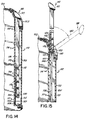
- the handle structure is best illustrated in Fig. 5.
- a sheath in the form of a tube 30 is fixed to the forward end wall 14 inside the shell 11.
- the tube 30 has an ID greater than the OD of handle 20, thereby permitting handle 20 to telescope within the tube 30.
- the tube 30 is snapped into a bracket 31.
- the tube is mounted in a hole 32 formed in the upper wall 16 of the shell.
- the tube 30 is enclosed by caps 34 and 35.
- the cap 34 at the upper end has an opening 37 through which the handle 20 passes.
- a friction sealing washer 38 is mounted between the cap 34 and the upper end of the tube 30 to form a seal between the handle and the shell and to provide friction for maintaining the handle in an intermediate position such as is shown in Fig. 2.
- a pin 40 passes through the lower end of the handle 20.
- the upper end 41 of the spring 26 is connected to the pin 40.
- the upper end of a flexible strap 45 is also connected to the pin 40.
- a cylindrical stop 46 is slidable in the tube 30, but has too great a diameter to pass through the hole 37 in the cap 34 at the top of the tube.
- a pin 47 passes through the stop 46.
- the lower end 48 of the spring 26 is connected to the pin 47 and the lower end 49 of the strap 45 is connected to the pin.
- connectors other than the spring 26 and strap 45 combination will be satisfactory. This will be demonstrated by reference to the embodiment of Figs. 12 to 15.
- the shell has a recess 50 into which the crossbar handle grip 21 sits when the handle is fully retracted, as shown in Fig. 1.
- the bottom wall 19 of the luggage is shown in Figs. 7 and 8.
- the lid 12 and shell 11, respectively, are recessed at 55 and 56 creating wheel wells to receive major wheels 57.
- the major wheels are preferably at least about 5 cm (two inches) in diameter.
- An L-shaped backing plate 58 is riveted at 59 to the bottom wall on the shell 11 and lid 12, respectively.
- An axle 60 is secured by a nut 61 to mount each major wheel 57 to the luggage.
- Minor castered wheels 62 (about 2.5 cm (one inch) in diameter) are mounted on each end of the bottom wall 19.
- the lower surface of the castered wheels preferably is above the lower surface of the major wheels when the wall 19 is in a horizontal attitude. This arrangement permits only a three-wheel support, as illustrated in Fig. 6.
- the handle In operation, the handle is normally retracted, as shown in Fig. 1.
- the handle can be raised to and frictionally held in an intermediate position, as shown in Fig. 2. This permits the user to stand alongside the luggage and push on the handle 20 to inch the luggage along while standing in an airport ticket line, for example.
- the handle To position the handle in an attitude for pulling the luggage, the handle is first raised to a fully vertically-extended position shown in Fig. 3. In this position, the spring 26 and strap 45 project out of the shell. The handle can be put in a pulling attitude by leaning it forward and flexing the spring and the strap. When the handle is released, the spring urges the handle back to its vertical position so that it can be retracted into the shell simply by pushing down on it.
- the strap provides a tensile element that prevents the spring from extending and retracting with a springiness that would diminish control when the luggage is being pulled.
- the luggage has a rigid bottom section 70.
- the bottom section 70 is basket-shaped and has side walls 71 and end walls 72.
- a rigid frame 73 projects upwardly from the bottom section 70.
- the frame 73 is generally rectangularly-shaped and has a bottom strap 74 that is riveted to the bottom section 70.
- a soft-sided upper section 78 has a central inverted U-shaped rigid strap 79 by which the upper section is attached to the frame 73.
- a lower rim 80 is secured around the perimeter of the lower edge of the fabric and seats on a mating rim 81 forming the upper edge of the bottom section 70, the two rims being joined as by stitching, as shown in Fig. 11, to connect the soft-sided upper portion 78 to the bottom section 70.
- a handle 82 is riveted to the strap 79.
- the frame 73 carries a tube 85 forming a sheath for a telescoping rigid handle 86.
- the handle is formed as depicted in Fig. 5 but admits of variations which will permit the handle to telescope and to pivot forwardly, as shown in Fig. 9.
- the frame 73 has a shoulder 87 to which the upper end of the tube 85 is connected.
- the soft-sided upper section 78 is also shouldered as at 88 to seat on the shoulder 87 and to form a recess for receiving the transverse hand grip 89 on the rigid handle 86.
- a soft-sided lid 90 is fastened to and forms a part of the upper section 78 by means of a stitched connection at its bottom edge and a zippered section around its perimeter, as is conventional.
- the bottom section 70 has recesses 92 on each side forming wells for major wheels 93. Internally, the bottom section 70 has a U-shaped steel bracket 94 to which the major wheels 93 are rotatably mounted. Castered minor wheels 96 are mounted on the bottom section adjacent each end of the luggage (see Fig. 9).
- the operation of the soft-sided luggage is identical to that of the hard-sided luggage.
- the handle 100 is an elongated flat element having, at its upper end, a handle grip 101.
- the luggage 102 is recessed at a corner 103 to receive the handle grip 101.
- the luggage has a shell 105 as in the embodiment shown in Figs. 1 to 8.
- the shell has a bottom wall 106 recessed at 107 to receive large intermediate wheels 108.
- the shell has an end wall 110.
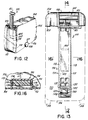
- a sheath 112 is formed in the end wall 110.
- the sheath is formed in part by the shell end wall 110 and by a handle guide 114.
- the handle guide is U-shaped in cross-section (Fig. 16) and has a pair of side walls 115 and an inner wall 117.
- the side walls have vertical channels 118.
- the inner wall 117 has vertically spaced recesses at the lower end 120, the upper end 121, and intermediate recesses 122 and 123.
- the pull handle 100 is flat and generally rectangular in cross-section. At its lower end, a leaf spring 125 is secured by screws 126 to the handle 100.
- the leaf spring has a free downwardly projecting portion 127 which has a detent 128 that projects toward the inner wall 117 of the handle guide 114.
- the handle at its lower end, has a transverse pin 130 having ends 131 projecting from the handle into the channels 118 of the handle guide.
- a stop At the upper end of the channels 118 a stop (not shown), the stop being engageable by the transverse pin 130 to limit the upper extent of the movement handle.
- the handle is normally held in its telescoped position of Fig. 14 by the spring detent 128 being disposed in the recess 120 at the lower end of the sheath in which the handle slides.
- the handle When the handle is to be used as a pull, it is raised to its fullest extent, as shown in Fig. 15. There the detent 128 drops into the upper recess 121. Further, the transverse pin 130 engages the stop 132 at the upper end of the channel 118. The handle can be raised no further. In this raised position, the handle can be swung to a forward inclined position as shown at 140 so that the luggage can be pulled along the floor, rolling principally on the wheels 108. In pulling the handle forward as shown at 140, the spring 125 is bent, stressing it so that when the handle is released, it naturally will swing back to the vertical position shown in full lines in Fig. 15.
- the handle can be adjusted to an intermediate position and maintained there by the detent 128 dropping into either of the recesses 122 and 123.
- the handle In that intermediate position, such as depicted in Fig. 12, the handle is in an ideal position for inching the luggage along as when standing in line at the airline ticket counter.
Claims (15)
- Gepäckstück, umfassend ein Behältnis (10) mit Wänden einschließlich einer Bodenwand (19, 70, 106) und einer Stirnwand (14, 72, 110), ein Radsystem (57, 62, 93, 96, 108), das an der oder an die Bodenwand (19, 70, 106) angrenzend befestigt ist, einen starren Griff (20, 86, 100) mit einem unteren Ende (25), Mittel (30, 85, 112) zum Befestigen des Griffes (20, 86, 100) an einer Innenfläche des Behältnisses (10) zur Bewegung zwischen einer zurückgezogenen Position, in der der Griff (20, 86, 100) in dem Behältnis (10) zurückgezogen ist, und einer ausgezogenen Position, in der der Griff (20, 86, 100) aus dem Behältnis (10) herausragt, und ein Mittel (26, 45 130), das das untere Ende (25) des Griffes (20, 86, 100) zu dem Gepäckstück dreht, um das Schwenken des Griffes (20, 86, 100) in eine geneigte Position zum Ziehen des Gepäckstückes zuzulassen, gekennzeichnet dadurch, daß die Befestigungsmittel (30, 85, 112) den Griff (20, 86, 100) an einer Innenfläche der Stirnwand (14, 72, 110) des Behältnisses (10) befestigen und daß ein Federmittel (26, 125) vorgesehen ist, das den Griff (20, 86, 100), wenn er sich in der ausgezogenen Position befindet, in eine vertikale Stellung drückt.
- Gepäckstück, umfassend ein Behältnis (10) mit Wänden einschließlich einer Bodenwand (19, 70, 106) und einer Stirnwand (14, 72, 110), ein Radsystem (57, 62, 93, 96, 108), das an der oder an die Bodenwand (19, 70, 106) angrenzend befestigt ist, einen starren Griff (20, 86, 100) mit einem unteren Ende (25), Mittel (30, 85, 112) zum Befestigen des Griffes (20, 86, 100) an einer Innenfläche des Behältnisses (10) zur Bewegung zwischen einer zurückgezogenen Position, in der der Griff (20, 86, 100) in dem Behältnis (10) zurückgezogen ist, und einer ausgezogenen Position, in der der Griff (20, 86, 100) aus dem Behältnis (10) herausragt, und ein Mittel (26, 45, 1301, das das untere Ende (25) des Griffes (20, 86, 100) zu dem Gepäckstück dreht, um das Schwenken des Griffes (20, 86, 100) in eine geneigte Position zum Ziehen des Gepäckstückes zuzulassen, gekennzeichnet dadurch, daß die Befestigungsmittel (30, 85, 112) den Griff (20, 86, 100) an einer Innenfläche der Stirnwand (14, 72, 110) des Behältnisses (10) befestigen und daß ein Mittel (38, 122, 123, 128) zum Halten des Griffes (20, 86, 100) in einer vertikalen Stellung in einer zurückgezogenen Zwischenposition zwischen den vollständig zurückgezogenen und vollständig ausgezogenen Positionen zur Erleichterung beim Ziehen an dem Griff zum Bewegen des Gepäckstückes um kleine Strecken vorgesehen ist.
- Gepäckstück nach Anspruch 2, das außerdem ein Federmittel (26, 125) umfaßt, das den Griff (20, 86, 100), wenn dieser in der ausgezogenen Position ist, in eine vertikale Stellung drückt.
- Gepäckstück nach Anspruch 1 oder 3, bei dem das Federmittel eine Blattfeder (125) und ein Mittel (126) zum Befestigen der Blattfeder an dem unteren Ende des Griffes (100) umfaßt.
- Gepäckstück nach einem vorhergehenden Anspruch, bei dem das Befestigungsmittel (30, 85, 112) eine Hülle (30, 85, 112) in der Stirnwand umfaßt, die an ihrem oberen Ende offen ist, wobei der Griff (20, 86, 100) in der Hülle (30, 85, 112) starr und verschiebbar ist.
- Gepäckstück nach Anspruch 5 bei Abhängigkeit von Anspruch 4, bei dem die Hülle (112) eine vertikale Grifführung (114) und vertikale Nuten (118) mit Begrenzungsmitteln an ihren oberen Enden in der Grifführung (114) besitzt, und bei dem das Drehmittel einen Querstift (130) umfaßt, der in dem unteren Ende des Griffes (100) befestigt ist und Enden (131) besitzt, die in die Nuten (118) ragen, um die Aufwärtsbewegung des Griffes (100) zu begrenzen.
- Gepäckstück nach Anspruch 6, bei dem die Blattfeder (125) nach unten unter den Griff (100) ragt, wobei die Blattfeder (125) eine seitlich hervorstehende Arretierung (128) besitzt, und bei dem vertikal beabstandete Aussparungen (120, 121, 122, 123) in der Grifführung (114) die Blattfederarretierung (128) aufnehmen, wenn der Griff (100) in zurückgezogenen, ausgezogenen und Zwischenpositionen ist.
- Gepäckstück nach Anspruch 5, bei dem die Hülle (30, 85, 112) ein längliches Rohr (30, 85) umfaßt, das an der Stirnwand (14, 72) befestigt ist.
- Gepäckstück nach einem vorhergehenden Anspruch, bei dem der Griff (20, 86, 100) einen Querstab (21, 89, 101) an seinem Ende und die obere Wand (16, 73, 102) des Behältnisses (10) eine Aussparung (88, 103) besitzt, um den Querstab (21, 89, 101) aufzunehmen, wenn der Griff (20, 86, 100) in dem Behältnis (10) zurückgezogen ist.
- Gepäckstück nach einem vorhergehenden Anspruch, bei dem der Griff (20, 86, 100) an einer vorderen Stirnwand (14, 72, 110) des Behältnisses (10) vorgesehen ist, bei dem das Radsystem ein Paar von Haupträdern (57, 93, 108), die an Querachsen (60, 94) drehbar befestigt sind, die an dem Gepäckstück an die Bodenwand (19, 70, 106) angrenzend befestigt sind, wobei die Haupträder (57, 93, 108) in Längsrichtung zwischen der vorderen Stirnwand (14, 72, 110) und einer hinteren Stirnwand (15, 72) zentriert sind, und eine Lenkrolle (62, 96) umfaßt, die an der Bodenwand (14, 72, 110) benachbart zu jeder Stirnwand (14, 15, 72, 110) befestigt ist, und bei dem das Gepäckstück beim Ziehen hauptsächlich auf den Haupträdern (57, 93, 108) rollt, wobei die Haupträder (57, 93, 108), die sich auf festen Achsen befinden, die Gepäckstückspur in der Richtung, in der es gezogen wird, halten, während die Lenkrollen (62, 96) für eine reibungsarme Bodenauflage für das vordere und hintere Ende der Bodenwand (14, 72, 110) sorgen.
- Gepäckstück nach Anspruch 10, bei dem die Haupträder (57, 93, 108) bodenberührende Oberflächen besitzen, die unterhalb der bodenberührenden Oberflächen der Lenkrollen (62, 96) liegen, wenn die Bodenwand (14, 72, 110) horizontal ist.
- Gepäckstück nach Anspruch 10 oder 11, das ein Paar von Seitenwänden (12, 71) und außerdem Mittel zum Bilden von Aussparungen (55, 92, 107) in den Seitenwänden (12, 71) umfaßt, die die Haupträder (57, 93, 108) aufnehmen.
- Gepäckstück nach Anspruch 12, das außerdem eine Platte (58, 94) umfaßt, die an der Innenseite jeder Seitenwand (12, 71) an die Aussparungen (55, 92, 107) angrenzend befestigt ist, wobei die Hauptradachsen (66, 94) an den Platten (58, 94) befestigt sind.
- Gepäckstück nach Anspruch 12 oder 13, bei dem die Aussparungen (57, 93, 108) mittig und an der Bodenwand (19, 70, 106) angrenzend sind und bei dem die Querachsen (60, 94) an den Seitenwänden (12, 71) an die Bodenwand (19, 70, 106) angrenzend befestigt sind.
- Gepäckstück nach einem der Ansprüche 12 bis 14, bei dem das Behältnis eine Schale (11, 105) mit einer Bodenwand (17, 106) und einer der Seitenwände (13) umfaßt, und bei dem das Gepäckstück einen Deckel (12) umfaßt, der eine Bodenwand (18), die an der Schalenbodenwand (11) angelenkt ist, und die andere Seitenwand umfaßt.
Applications Claiming Priority (3)
| Application Number | Priority Date | Filing Date | Title |
|---|---|---|---|
| US487459 | 1990-03-02 | ||
| US07/487,459 US5048649A (en) | 1990-03-02 | 1990-03-02 | Luggage with pull handle |
| PCT/US1991/001131 WO1991012744A1 (en) | 1990-03-02 | 1991-02-20 | Luggage with pull handle |
Publications (3)
| Publication Number | Publication Date |
|---|---|
| EP0517803A1 EP0517803A1 (de) | 1992-12-16 |
| EP0517803A4 EP0517803A4 (de) | 1994-01-26 |
| EP0517803B1 true EP0517803B1 (de) | 1996-10-02 |
Family
ID=23935801
Family Applications (1)
| Application Number | Title | Priority Date | Filing Date |
|---|---|---|---|
| EP91905669A Expired - Lifetime EP0517803B1 (de) | 1990-03-02 | 1991-02-20 | Koffer mit einem ziehgriff |
Country Status (19)
| Country | Link |
|---|---|
| US (1) | US5048649A (de) |
| EP (1) | EP0517803B1 (de) |
| JP (1) | JPH05506796A (de) |
| KR (1) | KR0137955B1 (de) |
| CN (1) | CN1030640C (de) |
| AT (1) | ATE143572T1 (de) |
| AU (1) | AU7461791A (de) |
| BG (1) | BG60946B1 (de) |
| BR (1) | BR9106102A (de) |
| CA (1) | CA2076548A1 (de) |
| DE (1) | DE69122498T2 (de) |
| ES (1) | ES2093095T3 (de) |
| FI (1) | FI923870A (de) |
| HK (1) | HK1004516A1 (de) |
| HU (1) | HUT64679A (de) |
| RO (1) | RO109030B1 (de) |
| RU (1) | RU2082304C1 (de) |
| SG (1) | SG46341A1 (de) |
| WO (1) | WO1991012744A1 (de) |
Cited By (3)
| Publication number | Priority date | Publication date | Assignee | Title |
|---|---|---|---|---|
| US10086508B2 (en) | 2014-07-22 | 2018-10-02 | Milwaukee Electric Tool Corporation | Tool storage devices |
| USD844324S1 (en) | 2015-07-17 | 2019-04-02 | Milwaukee Electric Tool Corporation | Bag |
| WO2019238228A1 (en) | 2018-06-13 | 2019-12-19 | Samsonite Ip Holdings S. À R.L. | Luggage article split along front and rear major faces |
Families Citing this family (73)
| Publication number | Priority date | Publication date | Assignee | Title |
|---|---|---|---|---|
| US5181590A (en) * | 1990-03-02 | 1993-01-26 | American Tourister, Inc. | Luggage frame with pull handle |
| US5197579A (en) * | 1990-03-02 | 1993-03-30 | American Tourister, Inc. | Luggage with pull handle |
| FR2661807B1 (fr) * | 1990-05-09 | 1995-04-28 | Sicma Consens Sarl | Dispositif de traction de bagages a roulettes. |
| US5165508A (en) * | 1991-12-23 | 1992-11-24 | Airway Industries, Inc. | Luggage case with pull handle |
| US5253739A (en) * | 1992-03-19 | 1993-10-19 | Samsonite Corporation | Wheeled flight bag with retractable pull handle |
| US5230408A (en) * | 1992-05-11 | 1993-07-27 | Imports By Brian Incorporated | Automatically extending anti tip-over device for wheeled luggage |
| US5379870A (en) * | 1992-05-11 | 1995-01-10 | Imports By Brian Incorporated | Anti tip-over device for wheeled luggage |
| FR2691338A1 (fr) * | 1992-05-25 | 1993-11-26 | Delsey Soc | Dispositif de support à roulettes et bagages incorporant au moins un tel dispositif. |
| US5323887A (en) * | 1992-06-24 | 1994-06-28 | York Partners, L.P. | Luggage case on wheels |
| US5316096A (en) * | 1992-07-22 | 1994-05-31 | Good Marketing, Inc. | Portable motorized suitcase |
| AU662558B2 (en) * | 1992-09-25 | 1995-09-07 | King-Sheng Wang | Luggage |
| US5330037A (en) * | 1992-09-15 | 1994-07-19 | Wang King Shen | Wheeled travel bag with adjustable handle |
| US5207440A (en) * | 1992-10-05 | 1993-05-04 | Joseph Liang | Article of wheeled, steerable luggage |
| US5295565A (en) * | 1992-12-15 | 1994-03-22 | Purdy Neat Things Company | Wheeled luggage |
| US5307908A (en) * | 1992-12-18 | 1994-05-03 | Shyr Michael H | Expandable tote bag with wheels |
| US5339934A (en) * | 1993-01-25 | 1994-08-23 | Joseph Liang | Luggage steering device |
| US5370409A (en) * | 1993-04-13 | 1994-12-06 | Latouche; Paul J. | Towable mobile fluid carrier |
| US5464080A (en) * | 1993-07-29 | 1995-11-07 | Liang; Joseph | Universally pivotal luggage steering apparatus |
| US5394965A (en) * | 1993-09-17 | 1995-03-07 | Kho; Dick T. | Attachable pull handle for suitcases |
| US5492346A (en) * | 1993-09-21 | 1996-02-20 | 21 Fathoms | Scuba tote |
| US5435423A (en) * | 1993-10-08 | 1995-07-25 | Royalox International, Inc. | Rolling catalog case with pull-out handle |
| US5456342A (en) * | 1993-10-08 | 1995-10-10 | Royalox International, Inc. | Rollable luggage |
| US5431263A (en) * | 1993-11-30 | 1995-07-11 | Lenox, Incorporated | Mobile carry-on suitcase |
| US5464081A (en) * | 1994-07-06 | 1995-11-07 | Zwanzig; Joy T. | Concealed type retractable suitcase handle |
| US5924533A (en) * | 1994-07-15 | 1999-07-20 | Samsonite Corporation | Luggage case |
| GB2293092A (en) * | 1994-08-31 | 1996-03-20 | Yi Chen Lin | Dragging device for a wheeled suitcase |
| US5497865A (en) * | 1994-09-19 | 1996-03-12 | Yun-Pi; Wu | Retractable travel bag handle assembly |
| US5645146A (en) * | 1994-11-08 | 1997-07-08 | Airway Industries, Inc. | Suitcase with retractable pull handle |
| US5547052A (en) * | 1994-12-09 | 1996-08-20 | Purdy Neat Things Company, Inc. | Modular wheeled luggage system, wheeled luggage, garment bag and connector for same |
| US5533601A (en) * | 1995-07-13 | 1996-07-09 | Wang; King-Sheng | Hidden type retractable handle assembly for a suitcase |
| US5620070A (en) * | 1995-11-14 | 1997-04-15 | Wang; Chien-Shan | Pull handle structure for a trunk |
| US5839738A (en) * | 1996-01-03 | 1998-11-24 | Chrysler Corporation | Wheeled cooler module with storage for vehicle |
| US5833039A (en) * | 1996-01-05 | 1998-11-10 | Skyway Luggage Company | Soft luggage handle assembly for wheeled case |
| US5943936A (en) * | 1996-03-08 | 1999-08-31 | Samsonite Corporation | Wheeled luggage case with extendable handle |
| US5803470A (en) * | 1996-05-01 | 1998-09-08 | Smith; Jayne E. | Stroller transporting device |
| US5722118A (en) * | 1996-06-28 | 1998-03-03 | Jetset Design | Handle conversion apparatus |
| IT1295707B1 (it) * | 1997-02-07 | 1999-05-27 | Fabio Pedrini | Articolo di valigeria con ruote ed organo di traino estraibile |
| US6129365A (en) * | 1997-07-01 | 2000-10-10 | Outrigger, Inc. | Inclined handle for wheeled case |
| US6536787B1 (en) | 1999-10-18 | 2003-03-25 | Lifestyle International Inc. | Multi-wheel baseplate and baggage assembly |
| IT249710Y1 (it) * | 2000-01-21 | 2003-05-28 | Claudio Francesco Bellini | Dispositivo di impugnatura per un oggetto mobile montato su ruote in particolare per una valigia o un carrello portabagagli |
| US6692011B2 (en) * | 2000-10-16 | 2004-02-17 | Steelcase Development Corporation | Mobile pedestal with storable handle |
| US6651791B1 (en) * | 2000-11-02 | 2003-11-25 | Trg Accessories, Llc | Pivotal handle for towable baggage |
| US20030102195A1 (en) * | 2000-11-02 | 2003-06-05 | Mittleman David D. | Pivotal handle for towable baggage |
| AU2002232546A1 (en) * | 2000-11-02 | 2002-05-15 | Outrigger, Inc. | Extendable and angularly adjustable handle for wheeled luggage |
| US6711784B2 (en) | 2001-02-12 | 2004-03-30 | Jelmar | Handle conversion device |
| ITMI20020685A1 (it) * | 2001-04-16 | 2003-10-02 | Vidal Europa S A | Frigorifero portatile perfezionato |
| TW549024U (en) * | 2001-11-08 | 2003-08-21 | Chaw Khong Technology Co Ltd | Drawbar device for single bar suitcase |
| WO2004080228A2 (en) * | 2003-03-07 | 2004-09-23 | Trg Accessories, Llc | Rotatable handle for towable luggage |
| CN2614515Y (zh) * | 2003-03-22 | 2004-05-12 | 乔工科技股份有限公司 | 单把手双管拉杆的行李箱伸缩拉杆装置 |
| AU2004100214B4 (en) * | 2003-06-27 | 2005-02-03 | Landor & Hawa International Limited | Suitcase |
| US6898823B2 (en) * | 2003-07-22 | 2005-05-31 | James Tsai | Single-tube retractable handle assembly |
| GB0517720D0 (en) * | 2005-08-31 | 2005-10-05 | Lee Paul T H | Improved luggage |
| US8561769B2 (en) * | 2008-12-11 | 2013-10-22 | Scott E. Andochick | Stackable, towable luggage |
| DE202010008188U1 (de) | 2010-07-30 | 2010-11-04 | PARAT-Werk Schönenbach GmbH + Co. KG | Transportabler Container in Kofferform |
| US7984797B1 (en) * | 2010-10-08 | 2011-07-26 | Delsey Luggage, Inc. | Soft sided luggage case with independent wheel hub |
| USD681411S1 (en) * | 2011-08-30 | 2013-05-07 | Master Lock Company Llc | Ratchet lock |
| CN103121552A (zh) * | 2011-11-18 | 2013-05-29 | 北京声望声电技术有限公司 | 用于盛放麦克风的包装筒 |
| AT14545U1 (de) * | 2014-09-05 | 2016-01-15 | Pack Easy Ag | Rollkoffer |
| AU2015324614A1 (en) * | 2014-10-02 | 2017-05-18 | Travelpro Products, Inc. | Article of luggage and method of assembling |
| US9918532B2 (en) * | 2014-10-10 | 2018-03-20 | Contrail, LLC | Interchangeable luggage perimeter |
| US20160128442A1 (en) * | 2014-11-06 | 2016-05-12 | Eddie Bauer LLC | Rolling luggage with multiple modes of conveyance |
| US11109657B2 (en) | 2014-11-06 | 2021-09-07 | Eddie Bauer LLC | Rolling luggage with multiple modes of conveyance |
| US10219599B2 (en) | 2015-11-06 | 2019-03-05 | JRSK, Inc. | Hard-shell luggage systems |
| US10595608B2 (en) | 2015-11-06 | 2020-03-24 | JRSK, Inc. | Luggage system employing a telescopically-extendable handle and battery power supply assembly equipped with a semi-automatic battery power module ejection mechanism |
| US9872547B2 (en) | 2015-11-25 | 2018-01-23 | Milwaukee Electric Tool Corporation | Handle assembly for a case |
| ITUB20159427A1 (it) * | 2015-12-15 | 2017-06-15 | Revival Agency Ltd | Una valigia, preferibilmente rigida, con guscio esterno protettivo intercambiabile. |
| CN105747433B (zh) * | 2016-05-09 | 2017-12-26 | 林建安 | 一种设有折叠轮的行李箱 |
| US11357298B2 (en) | 2019-03-01 | 2022-06-14 | Travelpro Products, Inc. | Article of luggage with a bottom tray |
| USD979939S1 (en) | 2019-08-21 | 2023-03-07 | JRSK, Inc. | Luggage |
| USD979938S1 (en) | 2019-08-21 | 2023-03-07 | JRSK, Inc. | Luggage |
| USD965974S1 (en) | 2019-08-21 | 2022-10-11 | JRSK, Inc. | Luggage |
| USD952345S1 (en) | 2020-02-06 | 2022-05-24 | Contrail, LLC | Luggage corner guard |
| US11305801B2 (en) | 2020-03-16 | 2022-04-19 | Rosemonde W. Killy | Shopping cart and associated methods |
Family Cites Families (38)
| Publication number | Priority date | Publication date | Assignee | Title |
|---|---|---|---|---|
| US2002836A (en) * | 1933-12-04 | 1935-05-28 | Anastasio Petrocelli | Baggage carrier |
| US2392926A (en) * | 1943-07-26 | 1946-01-15 | Kelly Daniel Allcott | Hand luggage attachment |
| US2437029A (en) * | 1946-01-12 | 1948-03-02 | William B Howard | Collapsible shopping cart |
| US2510754A (en) * | 1947-11-18 | 1950-06-06 | Clarence F Norlin | Portable luggage having retractable wheels |
| US2581417A (en) * | 1948-07-29 | 1952-01-08 | Jones Wendell Cooley | Luggage carrier having projectable and retractible supporting rollers |
| US2596578A (en) * | 1949-03-05 | 1952-05-13 | Grace H Mcintyre | Wheeled suitcase |
| FR59346E (fr) * | 1949-06-09 | 1954-05-24 | Valise roulante | |
| US2706643A (en) * | 1953-01-29 | 1955-04-19 | George P Clark Company | Retractable handle |
| DE1140479B (de) * | 1960-07-30 | 1962-11-29 | Westfaelische Metall Ind K G H | Hebelroller zum Bewegen und Lenken eines fahrbaren Transportbehaelters |
| US3526921A (en) * | 1968-10-16 | 1970-09-08 | Jean A Aupke | Suitcase castor mounting |
| US3522955A (en) * | 1969-01-16 | 1970-08-04 | Hideaway Handles Inc | Extendable handle assembly |
| US3606372A (en) * | 1969-05-21 | 1971-09-20 | Arthur J Browning | Wheeled luggage |
| US3655215A (en) * | 1970-06-05 | 1972-04-11 | Crate Rite Inc | Portable equipment case |
| FR2139578A5 (de) * | 1972-05-26 | 1973-01-05 | Taillet Joseph | |
| USRE29036E (en) * | 1972-07-14 | 1976-11-16 | Luggage transport structure | |
| US3799568A (en) * | 1972-07-14 | 1974-03-26 | R Hager | Luggage transport structure |
| DE2356011C3 (de) * | 1972-11-13 | 1982-02-04 | Danincit ApS, Ishoej | Mobiler Reisekoffer |
| US3997038A (en) * | 1975-06-23 | 1976-12-14 | Brooks Walker | Wheeled suitcase |
| US3989128A (en) * | 1975-08-29 | 1976-11-02 | Brooks Walker | Wheeled suitcase |
| US4062429A (en) * | 1975-12-16 | 1977-12-13 | Tabor Martin A | Combined garment bag and carrier |
| FR2440167A1 (fr) * | 1978-10-30 | 1980-05-30 | Delsey Soc | Valise a roulettes |
| US4358006A (en) * | 1979-12-28 | 1982-11-09 | Samsonite Corporation | Rigid side arm device forming a guiding handle for suitcase |
| IT8021258V0 (it) * | 1980-03-21 | 1980-03-21 | Valextra Spa | Valigia su ruote con dispositivo di trascinamento incorporato. |
| US4299313A (en) * | 1980-07-07 | 1981-11-10 | Samsonite Corporation | Mobile luggage case handle assembly |
| DE3302672A1 (de) * | 1981-07-29 | 1984-08-23 | Wilhelm 7700 Singen Hübner | Handroll - einrichtung fuer reisekoffer |
| US4411343A (en) * | 1981-09-14 | 1983-10-25 | Khalil Ahmid Ibrahim Cassimally | Luggage trolley |
| DE3272180D1 (en) * | 1982-10-22 | 1986-08-28 | Gunter Schneider | Suitcase with castors |
| US4561526A (en) * | 1983-01-03 | 1985-12-31 | Samsonite Corporation | Steering and support handle for wheeled luggage |
| DE8300286U1 (de) * | 1983-01-07 | 1983-09-01 | Sudhaus Schloss- Und Beschlagtechnik Gmbh & Co, 5860 Iserlohn | Ziehgriff |
| US4538709A (en) * | 1983-07-11 | 1985-09-03 | The Huntington National Bank | Wheeled garment bag |
| ATE59136T1 (de) * | 1984-09-06 | 1991-01-15 | Samsonite Corp | Koffer und daran montierte bodenraeder. |
| US4618035A (en) * | 1985-04-09 | 1986-10-21 | James Mao | Collapsible and movable support for wardrobe |
| DE3636064A1 (de) * | 1986-10-23 | 1988-04-28 | Heinrich Schaefer | Koffer |
| US4838396A (en) * | 1987-03-06 | 1989-06-13 | Delsey Luggage Company | Luggage handle |
| US4848605A (en) * | 1987-04-08 | 1989-07-18 | Plastech International Inc. | Mobile pharmaceutical hopper |
| US4759431A (en) * | 1987-04-15 | 1988-07-26 | Samsonite Corporation | Travel bag with combination pull handle and auxiliary bag strap |
| US4771871A (en) * | 1987-06-30 | 1988-09-20 | Rudolf Lambracht | Luggage with self-contained convertible wheeled carrier |
| US4852705A (en) * | 1988-07-22 | 1989-08-01 | Cowan Jr Samuel C | Case with extendable wheels and handle |
-
1990
- 1990-03-02 US US07/487,459 patent/US5048649A/en not_active Expired - Fee Related
-
1991
- 1991-02-20 ES ES91905669T patent/ES2093095T3/es not_active Expired - Lifetime
- 1991-02-20 HU HU9202795A patent/HUT64679A/hu unknown
- 1991-02-20 SG SG1996003202A patent/SG46341A1/en unknown
- 1991-02-20 BR BR919106102A patent/BR9106102A/pt not_active Application Discontinuation
- 1991-02-20 JP JP91505987A patent/JPH05506796A/ja active Pending
- 1991-02-20 DE DE69122498T patent/DE69122498T2/de not_active Expired - Fee Related
- 1991-02-20 RU SU915053165A patent/RU2082304C1/ru active
- 1991-02-20 AT AT91905669T patent/ATE143572T1/de not_active IP Right Cessation
- 1991-02-20 WO PCT/US1991/001131 patent/WO1991012744A1/en active IP Right Grant
- 1991-02-20 CA CA002076548A patent/CA2076548A1/en not_active Abandoned
- 1991-02-20 RO RO92-01152A patent/RO109030B1/ro unknown
- 1991-02-20 AU AU74617/91A patent/AU7461791A/en not_active Abandoned
- 1991-02-20 EP EP91905669A patent/EP0517803B1/de not_active Expired - Lifetime
- 1991-03-02 CN CN91101381.4A patent/CN1030640C/zh not_active Expired - Lifetime
-
1992
- 1992-08-28 FI FI923870A patent/FI923870A/fi not_active Application Discontinuation
- 1992-09-01 KR KR92702107A patent/KR0137955B1/ko not_active IP Right Cessation
- 1992-10-01 BG BG96936A patent/BG60946B1/bg unknown
-
1998
- 1998-04-30 HK HK98103688A patent/HK1004516A1/xx not_active IP Right Cessation
Cited By (5)
| Publication number | Priority date | Publication date | Assignee | Title |
|---|---|---|---|---|
| US10086508B2 (en) | 2014-07-22 | 2018-10-02 | Milwaukee Electric Tool Corporation | Tool storage devices |
| USD844324S1 (en) | 2015-07-17 | 2019-04-02 | Milwaukee Electric Tool Corporation | Bag |
| WO2019238228A1 (en) | 2018-06-13 | 2019-12-19 | Samsonite Ip Holdings S. À R.L. | Luggage article split along front and rear major faces |
| US11712094B2 (en) | 2018-06-13 | 2023-08-01 | Samsonite Ip Holdings S.A R.L. | Luggage article split along front and rear major faces |
| EP4298951A1 (de) | 2018-06-13 | 2024-01-03 | Samsonite IP Holdings S.ÀR.L. | Entlang der vorder- und rückseite geteiltes gepäckstück |
Also Published As
| Publication number | Publication date |
|---|---|
| FI923870A0 (fi) | 1992-08-28 |
| US5048649A (en) | 1991-09-17 |
| RU2082304C1 (ru) | 1997-06-27 |
| ATE143572T1 (de) | 1996-10-15 |
| SG46341A1 (en) | 1998-02-20 |
| WO1991012744A1 (en) | 1991-09-05 |
| EP0517803A1 (de) | 1992-12-16 |
| FI923870A (fi) | 1992-08-28 |
| CA2076548A1 (en) | 1991-09-03 |
| ES2093095T3 (es) | 1996-12-16 |
| DE69122498D1 (de) | 1996-11-07 |
| KR0137955B1 (en) | 1998-05-15 |
| CN1030640C (zh) | 1996-01-10 |
| RO109030B1 (ro) | 1994-11-30 |
| HUT64679A (en) | 1994-02-28 |
| HK1004516A1 (en) | 1998-11-27 |
| DE69122498T2 (de) | 1997-04-24 |
| CN1054525A (zh) | 1991-09-18 |
| BR9106102A (pt) | 1993-02-24 |
| EP0517803A4 (de) | 1994-01-26 |
| BG60946B1 (en) | 1996-07-31 |
| JPH05506796A (ja) | 1993-10-07 |
| HU9202795D0 (en) | 1992-12-28 |
| AU7461791A (en) | 1991-09-18 |
Similar Documents
| Publication | Publication Date | Title |
|---|---|---|
| EP0517803B1 (de) | Koffer mit einem ziehgriff | |
| US5197579A (en) | Luggage with pull handle | |
| CA2208102C (en) | Roller mechanism for container or cart | |
| US5568848A (en) | Laterally movable suitcase with wheeled, pivotable leg | |
| EP1718183B1 (de) | Koffer mit rollen | |
| US5377795A (en) | Two-way towable luggage | |
| US5630521A (en) | Ergonomic upright wheeled luggage | |
| EP0804105B1 (de) | Ergonomisches senkrechtgepäck mit fahrrollen | |
| KR101393966B1 (ko) | 개선된 수하물 케이스 | |
| US5330037A (en) | Wheeled travel bag with adjustable handle | |
| WO1997018726B1 (en) | Ergonomic upright wheeled luggage | |
| EP0589023A1 (de) | Mit rädern versehene flugtasche mit einziehbarem handgriff | |
| EP3551005B1 (de) | Kofferschale und radsatz dafür | |
| CA2321530A1 (en) | Improvements in wheeled luggage and associated devices | |
| US20130062843A1 (en) | Wheeled apparatus for transporting loads | |
| AU747107B2 (en) | Roller mechanism for container or cart | |
| CA2170709A1 (en) | Suitcase with retractable rollers |
Legal Events
| Date | Code | Title | Description |
|---|---|---|---|
| PUAI | Public reference made under article 153(3) epc to a published international application that has entered the european phase |
Free format text: ORIGINAL CODE: 0009012 |
|
| 17P | Request for examination filed |
Effective date: 19920916 |
|
| AK | Designated contracting states |
Kind code of ref document: A1 Designated state(s): AT BE CH DE DK ES FR GB GR IT LI LU NL SE |
|
| A4 | Supplementary search report drawn up and despatched |
Effective date: 19931209 |
|
| AK | Designated contracting states |
Kind code of ref document: A4 Designated state(s): AT BE CH DE DK ES FR GB GR IT LI LU NL SE |
|
| 17Q | First examination report despatched |
Effective date: 19950424 |
|
| GRAG | Despatch of communication of intention to grant |
Free format text: ORIGINAL CODE: EPIDOS AGRA |
|
| GRAH | Despatch of communication of intention to grant a patent |
Free format text: ORIGINAL CODE: EPIDOS IGRA |
|
| GRAH | Despatch of communication of intention to grant a patent |
Free format text: ORIGINAL CODE: EPIDOS IGRA |
|
| RAP1 | Party data changed (applicant data changed or rights of an application transferred) |
Owner name: SAMSONITE CORPORATION |
|
| GRAA | (expected) grant |
Free format text: ORIGINAL CODE: 0009210 |
|
| ITF | It: translation for a ep patent filed |
Owner name: BARZANO' E ZANARDO ROMA S.P.A. |
|
| AK | Designated contracting states |
Kind code of ref document: B1 Designated state(s): AT BE CH DE DK ES FR GB GR IT LI LU NL SE |
|
| PG25 | Lapsed in a contracting state [announced via postgrant information from national office to epo] |
Ref country code: LI Effective date: 19961002 Ref country code: GR Free format text: LAPSE BECAUSE OF FAILURE TO SUBMIT A TRANSLATION OF THE DESCRIPTION OR TO PAY THE FEE WITHIN THE PRESCRIBED TIME-LIMIT Effective date: 19961002 Ref country code: DK Effective date: 19961002 Ref country code: CH Effective date: 19961002 Ref country code: AT Effective date: 19961002 |
|
| REF | Corresponds to: |
Ref document number: 143572 Country of ref document: AT Date of ref document: 19961015 Kind code of ref document: T |
|
| REF | Corresponds to: |
Ref document number: 69122498 Country of ref document: DE Date of ref document: 19961107 |
|
| ET | Fr: translation filed | ||
| REG | Reference to a national code |
Ref country code: ES Ref legal event code: FG2A Ref document number: 2093095 Country of ref document: ES Kind code of ref document: T3 |
|
| PG25 | Lapsed in a contracting state [announced via postgrant information from national office to epo] |
Ref country code: SE Effective date: 19970102 |
|
| PG25 | Lapsed in a contracting state [announced via postgrant information from national office to epo] |
Ref country code: LU Free format text: LAPSE BECAUSE OF NON-PAYMENT OF DUE FEES Effective date: 19970228 |
|
| REG | Reference to a national code |
Ref country code: CH Ref legal event code: PL |
|
| PLBE | No opposition filed within time limit |
Free format text: ORIGINAL CODE: 0009261 |
|
| STAA | Information on the status of an ep patent application or granted ep patent |
Free format text: STATUS: NO OPPOSITION FILED WITHIN TIME LIMIT |
|
| 26N | No opposition filed | ||
| PGFP | Annual fee paid to national office [announced via postgrant information from national office to epo] |
Ref country code: NL Payment date: 19971231 Year of fee payment: 8 |
|
| PGFP | Annual fee paid to national office [announced via postgrant information from national office to epo] |
Ref country code: FR Payment date: 19980209 Year of fee payment: 8 |
|
| PGFP | Annual fee paid to national office [announced via postgrant information from national office to epo] |
Ref country code: ES Payment date: 19980218 Year of fee payment: 8 |
|
| PGFP | Annual fee paid to national office [announced via postgrant information from national office to epo] |
Ref country code: DE Payment date: 19980227 Year of fee payment: 8 |
|
| PGFP | Annual fee paid to national office [announced via postgrant information from national office to epo] |
Ref country code: BE Payment date: 19980320 Year of fee payment: 8 |
|
| PG25 | Lapsed in a contracting state [announced via postgrant information from national office to epo] |
Ref country code: ES Free format text: LAPSE BECAUSE OF NON-PAYMENT OF DUE FEES Effective date: 19990222 |
|
| PG25 | Lapsed in a contracting state [announced via postgrant information from national office to epo] |
Ref country code: BE Free format text: LAPSE BECAUSE OF NON-PAYMENT OF DUE FEES Effective date: 19990228 |
|
| REG | Reference to a national code |
Ref country code: ES Ref legal event code: GD2A Effective date: 19990126 |
|
| BERE | Be: lapsed |
Owner name: SAMSONITE CORP. Effective date: 19990228 |
|
| PG25 | Lapsed in a contracting state [announced via postgrant information from national office to epo] |
Ref country code: NL Free format text: LAPSE BECAUSE OF NON-PAYMENT OF DUE FEES Effective date: 19990901 |
|
| PG25 | Lapsed in a contracting state [announced via postgrant information from national office to epo] |
Ref country code: FR Free format text: LAPSE BECAUSE OF NON-PAYMENT OF DUE FEES Effective date: 19991029 |
|
| PG25 | Lapsed in a contracting state [announced via postgrant information from national office to epo] |
Ref country code: DE Free format text: LAPSE BECAUSE OF NON-PAYMENT OF DUE FEES Effective date: 19991201 |
|
| REG | Reference to a national code |
Ref country code: FR Ref legal event code: ST |
|
| REG | Reference to a national code |
Ref country code: ES Ref legal event code: FD2A Effective date: 20010503 |
|
| REG | Reference to a national code |
Ref country code: GB Ref legal event code: IF02 |
|
| PGFP | Annual fee paid to national office [announced via postgrant information from national office to epo] |
Ref country code: GB Payment date: 20040107 Year of fee payment: 14 |
|
| PG25 | Lapsed in a contracting state [announced via postgrant information from national office to epo] |
Ref country code: IT Free format text: LAPSE BECAUSE OF NON-PAYMENT OF DUE FEES;WARNING: LAPSES OF ITALIAN PATENTS WITH EFFECTIVE DATE BEFORE 2007 MAY HAVE OCCURRED AT ANY TIME BEFORE 2007. THE CORRECT EFFECTIVE DATE MAY BE DIFFERENT FROM THE ONE RECORDED. Effective date: 20050220 Ref country code: GB Free format text: LAPSE BECAUSE OF NON-PAYMENT OF DUE FEES Effective date: 20050220 |
|
| GBPC | Gb: european patent ceased through non-payment of renewal fee |
Effective date: 20050219 |